

Page 1

Please remember to service this appliance annually
RO
MANUAL DE INSTALARE SI UTILIZARE
EXCLUSIVE C
NZ
Gas adaptive condensing boiler
Installation and user manual
INSTALLER AND USER MANUAL
Page 2

RANGE RATING
This boiler can be adapted to the heat requirements of the system, it is possible to set the range rated
parameter as shown in the specific paragraph. If applied the engineer must note the set value on the
adhesive label supplied for successive maintenance, engineers to refer to this adjusted value.
EN
0051
51C S4793
“Thank you for purchasing this Beretta Exclusive condensing boiler”
EXCLUSIVE C complies with basic requirements of the following Directives:
- Gas directive 2009/142/EC
- Efficiency directive: Article 7(2) and Annex III of directive 92/42/
EEC
- Electromagnetic compatibility directive 2014/30/EU
- Low-voltage directive 2014/35/EU
- Directive 2009/125/EC Eco design for energy-using appliances
- Directive 2010/30/EU Indication by labelling of the consumption of energy by energy-related products
- Delegated Regulation (EU) No. 811/2013
- Delegated Regulation (EU) No. 813/2013
Delegated Regulation (EU) No. 814/2013
Within this manual there are sections in red text these should be noted especially where they refer to safety
and the prohibition of actions other than by a qualified engineer The manufacturer is not Liable for any failure
to observe the requirements set out in this manual or relevant New Zealand code.
Some prohibited actions are also noted by the symbol P
Note : User relevant sections are presented with green text
The user must not perform operations on the safety devices, replacing parts of the product, tamper with or
attempt to repair the appliance. These operations must be entrusted exclusively to qualified persons.
Important note regarding service requirements
Servicing of this appliance must be carried out at 12 month intervals
The servicing engineer
Minimum service must include the specific actions listed
Pay specific attention to the requirement to replace the burner chamber seal at each service,
-
This instruction manual contains data and information for
both the user and the installer. The user of the use of the
appliance, must also refer to chapters:
• Warnings and safety (Next page)
• Maintenance
must pay particular attention to
Installer’s-user’s manual 3-28
Boiler operating elements 40
Electric diagrams 41
Hydraulic circuit 42
Circulator residual head 43
Pages 28 / 40 Service requirements
Page 3

ENGLISH
3
a
EN
ENGLISH NZ
INSTALLATION MANUAL
1 WARNINGS AND SAFETY
The boilers manufactured are inspected in the smallest detail in
order to protect users and installers against possible injury. After
installation check the electrical wiring, in particular stripped parts of
leads, which must not protrude from the terminal boards
This installer and user manual constitutes an integral part of this
product.. Make sure it is always kept with the appliance, even if it
is transferred to another owner or user, or moved to another heating
system. In case of loss or damage, please contact Heat IQ Technical
Assistance for a new copy.
This boiler may only be installed and serviced by personnel qualified
in accordance with current regulations.
The installer must instruct the user in the operation of the
appliance and about essential safety regulations.
This boiler must only be used for the application it was designed for.
The manufacturer accepts no liability within or without the contract
for any damage caused to people, animals and property due to
installation, adjustment and maintenance errors or to improper use.
After removing the packaging, make sure the content is in good
condition and complete. If not, contact the supplier immediately.
The safety valve outlet must be connected to a suitable collection
and drain system. The manufacturer declines all liability for damage
caused due to any intervention carried out to the safety valve.
The seal of the condensate drainage connection line must be fully
protected against the risk of freezing
Check that the rain water drainage channel of the flue and the
relative connection pipe are free of obstructions.
Dispose of waste by being careful not to harm human health and
without employing procedures or methods which may damage the
environment.
At the end of its life, the product should be not be disposed of as solid
urban waste, but rather it should be recycled.
During installation, inform the user that:
- In the event of water leaks, the water supply must be shut off and
the Installer contacted immediately
- Periodically check that the operating pressure of the hydraulic
system is between 1 and 1.5 bar. If it is not, contact the installer
If the boiler is unused for a long period we recommended
- Turn the main appliance switch and the main system switch to “off”
- Close the fuel and water valves for the heating and domestic hot
water system
Drain if there is a risk of freezing
Boiler maintenance must be carried out at least once a year;
s e rv i c in g mu s t b e ca r ri ed o ut by a suitably qualified
competent engineer
The appliance is not to be used by children
It is forbidden to touch the appliance while barefoot or if parts of your
body are wet.
Do no activate electric devices or appliances such as switches,
household appliances and so on if you notice a smell of Gas. In this
case:
- Ventilate the room by opening the doors and windows;
- Close the fuel shut-off device;
- Request the prompt intervention of a Gas fitter or service engineer
Any technical or cleaning operation is forbidden before isolating the
appliance from the power supply by turning the power point switch
to “OFF” and the main switch of the boiler to “OFF”.
Do not modify the safety or adjustment devices without the
manufacturer’s precise instructions.
.
Do not leave inflammable containers and substances in the room
where the appliance is installed.
Do not leave flammable containers and substances in the room
where the device is installed.
Do not leave packaging material in reach of children as it may be a
potential source of suffocation.
The condensate drain outlet must be run avoiding double trapping
Never carry out any Adjustment of the gas valve.
2 Boiler Description
EXCLUSIVE are equipped with a new ACC (Activate Combustion
Control) system.
This new control system, developed by Beretta, ensures functionality,
efficiency and low emissions under any conditions
.
The ACC system uses an ionisation sensor immersed in the
burner flame, whose information allows the control board to
operate the gas valve which regulates the fuel.
This sophisticated control system provides the auto-regulation of
the combustion, so there is no need for an initial calibration. The
ACC system is able to adapt the boiler to operate with different gas
compositions, different outlet pipes lengths and different altitudes
(within the specified design limits).
The ACC system can also perform an auto-diagnostic operation
that locks out the burner before the permitted upper emissions
limit is exceeded.
EXCLUSIVE is a type C condensing wall-hung boiler to be used for
heating and the production of domestic hot water: depending on
the fume discharge accessory used, it is classified in categories
C13,C13x; C33,C33x; C43,C43x; C53,C53x; C63,C63x; C83,
C83x; C93, C93x.
In configurations prefix C, this appliance can be installed in any
type of room
(There are no limitations due to ventilation conditions or room
volume).
Page 4

EXCLUSIVE
4
PARAMETERS
UM
HEATING CIRCUIT
WATER
FILLING WATER
pH value 7-8
-
Hardness
°F - 15-20
Appearance -
clear
3 INSTALLATION
3.1 Installation regulations
Installation must be carried out by qualified persons, in compliance
with the following reference standards:
- UNI 7129-7131
- CEI 64-8.
- NZ building and plumbing codes with reference to NZ standards
POSITION
EXCLUSIVE - a wall-hung boiler for heating and for the production of DHW.
with f lue gas discharge pipe and pick-up of combustion air from
outside. It does not require an air intake point in the installation area.
It must be installed using concentric pipes, or other types of
discharge designed for condensing boilers with an airtight chamber.
MINIMUM CLEARANCES
To ensure access to the boiler for normal maintenance operations, respect
the minimum installation clearances envisaged.
For correct appliance positioning, bear in mind that:
- It must not be placed above a cooker or other cooking device
- Heat-sensitive walls (e.g. wooden walls) must be protected by use of a
cement fiber board
It is ESSENTIAL to provide the necessary space for the introduction of an
analyser for the combustion analysis check. In fig. 6a P44 a
sample drawing where distances between boiler and cabinet/niche
were obtained using a 300mm length analyser probe.
3.2 Removing the casing
To access the components inside, remove the casing as indicated below:
-
Locate and unscrew the 2 screws (A - f
casing.
-
The noise absorbing panels inside the front and side walls ensure
the airtight seal for the air supply duct in the installation
environment. It is therefore ESSENTIAL after dismantling
operations to correctly reposition the components so as not to
compromise the boiler’s operation.
WARNING If damaged the front panel must be replaced.
Prior to ignition, make sure that the boiler is designed to operate
It is important to highlight that in some cases the flue is under
By leveraging the fixing clips (C - fig. 13), unhook the lower part of
the casing now
(B - fig. 13 P44), then
Under the safety valve, install a tundish with the corresponding
discharge in the event of leaks due to the overpressure of the heating
system. The domestic cold input must not exceed 6 Bar
with the gas available; this can be checked by the wording on the
packaging and by the adhesive label indicating the gas type.
pressure, so the joints of the various elements must be airtight.
lift the casing upwards to release it from the top tabs
remove the face panel.
3.3 Positioning and hydraulic
The boiler comes as standard with a boiler hanger jig. The position and
dimensions of hydraulic fittings are shown in Fig 8/9 on page 44
, proceed as follows:
- Fasten the boiler Bkt (F) to the wall and use a spirit level to make sure it
is perfectly horizontal
- Use the jig to identify the required pipe centers
-
The pipe template and hanger can then be removed
Install pipework
Using the valve kit supplied . include a magnetic filter (not supplied) in the
return line . A magnetic filter is a requirement of warranty
Note The 1st 1m (minimum) of pipe used for the flow and return line
should be run in copper.
The condensate and relief drain outlet must be run avoiding
double trapping
The system attached must include a low point drain for
flushing the system
3.4 Gas connection
Connection of the gas supply must be carried out in
compliance with current NZ installation standards. By a
certifying Gas fitter
Ensure the supply pipework supports the delivery of the relevant
Gas being used and is correctly sized.
If the appliance is to use LPG attach the Gas type label supplied
( Ref fig. 6-6a Page 44)
ig.
13) that f
ix
the front
connections
form the jig .
3.5 Electrical connections
(
Figure 10/11 Page 45)
Low voltage connections
Carry out the low voltage connections as follows:
- Use the external cable box supplied as standard
- Unscrew the fixing screws of the cover (V)
- Carry out the connections as shown in fig. 11
It is recommended to use wires with section not exceeding
0,5mm2. In case of TA or TBT connection, remove the respective
shunts
(fig. 12).
- Close the box with the screws that were previously removed
- Press the two tabs on the sides of the box to place it correctly in its
housing in the boiler sliding upward within the guide rails and tighten the
safety screw (V1)
If the low voltage electrical connection box is not connected the boiler
will not ignite.
High voltage connections
The connection to the mains supply must be made via a standard power
point. The appliance works with alternating current at 230 Volt/50 Hz, and
is in compliance with Standard EN 60335-1. (NZ Compliant)
It is obligatory to make the connection with a safe ground/earth,
The manufacturer will not be liable for any damage resulting incorrect or
absent earth connection.
.
3.6 Flue gas exhaust and combustion air suction
To evacuate combustion products, refer to UNI 7129-7131. Always comply
with local standards of the Fire Department, and with possible local
municipal dispositions.
The release of combustion products is assured by a centrifugal fan. The
control board constantly checks that it is operating correctly. It is essential
for evacuating fumes and induction of boiler combustion air that only
original flue pipes are used and that the connection is made correctly as
shown in the instructions provided with the flue gas accessories.
A single flue can be connected to several appliances provided that every
appliance is the condensing type.
The boiler is a C-type appliance (with airtight chamber), and must therefore
have a safe connection to the flue gas discharge pipe and to the
combustion air suction pipe; these carry their contents too and from
outside, and are essential for the operation of the appliance.
Both concentric and twin terminals are available.
3.7 Filling the heating system (fig. 16)
Note:
Even though the boiler is fitted with a semi-automatic filling
device, the first filling operation must be carried out by using the filler tap
(B) with the boiler in the off position.
Filling
- Open the caps of the lower (A) automatic air vent valve by two or
- Open the filling tap (B) until the pressure indicated by the water pressure
-
On going venting of the boiler takes place automatically via the two
3.8 Flush and Protect
In the case of a new installation or replacement of the boiler, it is necessary
to pre flush the heating system
To ensure the device operates well and is protected from scale and
corrosion add inhibitors, antifreeze etc as required and check the
parameters in the table are within the values indicated.
Failures as result of not flushing the system will not be covered.
. must be carried out when the system is cold, as follows.
Three turns; to allow a continuous venting of the air, leave valve
A open.
gauge is between 1 and 1.5 bar
Re-close the filling tap.
automatic vent valves positioned on the circulator & top point
Page 5

ENGLISH
5
Maximum straight length
Pressure drop
25C
30C
35C
bend
45°
bend
90°
Concentric pipe
Ø 60-100 mm
(horizontal)
10 m 10 m 8 m 1,3 m
1,6 m
Concentric pipe
Ø 60-100 mm
(vertical)
11 m 11 m 9 m 1,3 m
1,6 m
Concentric pipe
Ø 80-125 mm
25 m
25 m
20 m
1 m
1,5 m
Twin pipe Ø 80 mm
70+70 m
50+50 m
35+35 m
1 m
1,5 m
Flue Suction/discharge pipes length table
“Straight length” means with terminals and joints but without bends.
The boiler is supplied without the flue,
Allowing you to use the accessories for condensing appliances that
most suit the installation characteristics (see catalogue).
. It is compulsory to use the Beretta flue components.
Flue gas outlets are potential sources of danger. Ensure they
remain clear
The use of longer flue causes a minor loss of output of the boiler
Make sure the flue gas discharge pipe is tilted 3° towards the
boiler.
The boiler is designed to take in and dispose of flue gas
condensate and/or meteoric water condensate deriving from the
flue gas discharge system using its own siphon.
Flue installation
Concentric pipes (ø 60-100 mm)
- Position the bend so that the Ø 60 pipe goes fully into the flue gas
turret of the boiler.
- Once positioned, make sure that the 4 notches (A) on the flange connect
to the groove (B) on the Ø100 of the bend.
- Fully tighten the two locking terminals of the flange (C) so the bend itself
is restrained.
-
Twin pipes (ø 80 mm)
The combustion air suction pipe should be selected from the two inputs,
remove the closing plug fixed with the screws and
deflector.
- Position the adaptor on the flue gases pipe so that the Ø 60 pipe goes
fully into the flue gases turret of the boiler
- Once positioned, make sure that the 4 notches (A) on the flange connect
to the groove (B) on the Ø100 of the adaptor.
- Fully tighten the two locking terminals of the flange (C) so the adaptor
itself is restrained.
- For Twin pipes in NZ seek advice from heat IQ
SPIECIAL ITEM
- see graphs fig. 18
ix
Concentric pipes (ø 80-125 mm)
- Position the adaptor so that the Ø60 pipe goes fully into the f lue turret
of the boiler.
- Once positioned, make sure that the 4 notches (A) on the flange connect
to the groove (B) on the Ø100 of the adaptor.
- Fully tighten the two locking terminals of the flange (C) so the adaptor
itself is restrained.
-
Then f
it
the Ø 80-125 adaptor kit on the vertical fitting.
the specific air
Page 6

6
EXCLUSIVE
a
LED status
CIRCULATOR status
Consumption in
% of MAX P1 (*)
Green LED on +
1 yellow LED on
Operating at minimum
0~25
Green LED on + 2
yellow LEDs on
Operating at
minimum-medium
25~50
Green LED on +
3 yellow LEDs on
Operating at medium-
maximum
50~75
Green LED on +
4 yellow LEDs on
Operating at maximum
100
LED status
ALARM
description
Status
CIRCULATOR
Possible
SOLUTION
Red LED on +
1 yellow LED
on (LED 5)
The drive shaft is
jammed
Start attempt
every 1.5
seconds
Wait or unjam
the drive shaft
Red LED on +
1 yellow LED
on (LED 4)
Low input
voltage
Warning only.
The circulator
continues to
operate
Check the
input voltage
Red LED on +
1 yellow LED
on (LED 3)
Electrical power
supply fault or
faulty circulator
The circulator is
stopped
Check the electrical
power supply or
replace the
circulator
3.9 Elimination of air from the heating circuit
and
from the boiler
(fig. 7)
During initial installation, or in the event of extraordinary
maintenance, you are advised to perform the following sequence
of operations:
1. Open by two or three turns the automatic relief valve cap (A) and leave
it open.
2. Open the system filling tap located under the appliance.
3. Switch on the electricity supply to the boiler, leaving the gas tap turned
off.
4. Activate a heat request via the room thermostat or the remote control
panel, so that the 3-way valve goes into heating mode.
5. Activate a request for DHW as follows: open a tap for 30 seconds so
that the three-way valve cycles from heating to DHW and vice versa for
about ten times (in this situation, the boiler will go into alarm due to lack
of gas, simply reset it whenever this is proposed).
6. Continue the sequence until no more air is coming from the air vent
valve.
7. Check the system pressure level is correct (the ideal level is 1 bar).
8. Turn off the system filling tap.
Turn on the gas tap and ignite the boiler
3.10
Draining the heating system
Before draining, switch off the electricity supply by turning off the main
switch of the system.
- Close the heating system’s flow and return valves.
- Connect a hose to the system drain valve (C).
- Manually loosen the system drain valve (C).
-
(fig. 16)
3.11 Emptying the domestic hot water system
If there is risk of frost, the domestic hot water system must be emptied in
the following way:
- turn off the main water inlet supply tap on the boiler
- turn on all the hot taps to drain.
3.12 Circulation pump settings
Modify only in specific circumstances
Circulator residual discharge head
The boiler is equipped with an already hydraulically and
electrically connected circulating pump, its useful available
performance is indicated in the graphs at page 43.
The circulator comes set from the factory with a 6 meter discharge
head curve. The boiler is equipped with an anti-seize system
which starts up an operation cycle every 24 hours in standby
mode
The “anti seize” function is active only if the boiler is electrically powered.
Operating the circulation pump without water is strictly forbidden.
If you need to use a different curve you can select the desired level on the
circulator. The main characteristics and the way to set up their desired
operation are listed. Below
3.12.1 Pump on board User interface
The user interface is made up of a button (A), a two-colored red / green
LED (B) and four yellow LEDs (C) arranged in a row.
The user interface allows the operating performance to be viewed (operating
status & alarm status) , it also allows the circulator operating modes to be
set.
The performance, indicated by the LEDs (B) and (C) is always visible during
normal operation of the circulator whereas settings can be carried out by
pressing the button (A).
3.12.2 Operating status indication
When the circulator is in operation the LED (B) is green. The four yellow
LEDs (C) indicate the electrical energy consumption (P1) as shown in the
following table.
(*) For the power (P1) absorbed by the circulator see the indications in the
“Technical Data” table.
3.12.3 Alarm status indication
If the circulator has detected one or more alarms the two-colour LED (B)
will be red. The four yellow LEDs (C) indicate the type of alarm as shown
in the following table.
If there are several alarms the circulator will display only the alarm with
the highest priority.
3.12.4 Display of active settings
With the circulator powered, press briefly on the button (A) to view the active
configuration of the circulator. The LEDs indicate the active settings.
In this phase no variations can be made to the circulator configuration.
Two seconds after the button (A) has been pressed the user interface
returns to the normal operating status display.
3.12.5 Key lock function
The purpose of the key lock function is to prevent accidental modifications
to the settings or the improper use of the circulator.
When the key lock function is activated, long-pressing the button (A) is
prevented. This prevents the user from entering the circulator’s operating
modes setting section.
Enabling/disabling the key lock function is achieved by pressing the button
(A) for more than 10 seconds. During this step all of the LEDs (C) will lash
for 1 second.
Page 7

7
ENGLISH
A. Operating status display
B. Settings display
C. Settings
Configuration
B
C
A
D
E
25-30 kW
F
35 kW
D
F
E
3.12.6 Changing the pump operating mode
In normal operating conditions the circulator works with the factory settings
or the last settings carried out.
To change the configuration:
Ensure that the key lock function is deactivated.
Press the button (A) for more than 2 seconds until the LEDs begin to
flash. Short-press the button (A) within 10 seconds and the user interface will
move on to display the next settings. The various available settings will
appear in a cyclic sequence.
If the button (A) is not pressed, the last setting will be stored.
IMPORTANT
If the 3 = (5 metres) or 4 = (4 metres) curves are set the bypass must be
replaced with the one supplied,
Follow the procedure indicated below:
Remove boiler electrical power by setting the system’s main switch to off.
Close the system taps and empty the boiler heating circuit.
Extract the bypass body cover fixing spring (D).
Extract the bypass body cover (E).
Replace the bypass valve (F) with the one included with the boiler.
Refit the bypass body cover and its spring.
If the button (A) is pressed you can move back to the “active settings display”
again and check that the LEDs (B) and (C) indicate (for 2 seconds) the last
setting carried out.
If the button (A) is not pressed for more than 2 seconds the user interfaces
switches to the “Operating status display”.
The available settings are shown in figure along with related representation
of LED (B) and (C).
Page 8

8
EXCLUSIVE
LED
Light signal indicating the operating status of the boiler. Can be red or green (see specific paragraph)
REC10
Boiler control panel
Key area
ok= confirm
back= return to the previous screen
cancel selection
return to the main screen (press > 2 sec.)
up= allows you to choose between the options PLANT-STATE-SET-INFO-MENU and to surf through the
submenus scrolling upwards
down= allows you to choose between the options PLANT-STATE-SET-INFO-MENU and to surf through the
submenus scrolling down
This icon indicates that the OFF operating status mode has been set. Each ignition request is ignored except for the anti-freeze function. The pump
anti-lock, 3-way valve and anti-freeze function remain active.
This icon indicates that WINTER mode has been selected (HEATING function enabled). If a heating request from the main zone is in progress, the
icon will be flashing.
This icon indicates that the circuit for domestic hot water production is enabled. When a domestic hot water request is in progress, the icon flashes.
The P at the top of the domestic hot water icon indicates that the boiler preheating function is enabled; the P when flashing indicates that a preheating
request is in progress.
When the “central heating programming timing” is enabled this icon indicates that the system heating (main zone) is in AUTOMATIC mode (the
management of the heating requests follows what has been set with the timer).
If the heating function is not enabled during the current time frame, the icon will be crossed out.
When the “central heating programming timing” is enabled this icon indicates that the system heating (main zone) is in MANUAL mode (the
management of the heating requests does not follow what has been set with the programming timing, but it is always active).
OFF
This icon indicates that the system (main zone) has been set to off (not active).
This icon indicates that the system is detecting the presence of a flame.
This icon indicates the presence of an anomaly, and is always flashing.
4 CONTROL PANEL (REC10)
The REC10 remote control has the function of machine interface,
Displaying the system and providing access to the parameters.
The middle of the main screen displays the temperature of the domestic
hot water probe, unless there is a heat request is in progress, in this
case the delivery temperature of the boiler at that particular time is
displayed.
The value expressed in bar refers to the system’s water pressure.
The top of the screen shows the information regarding the current date
and time, as well as the outdoor temperature, if available.
On the left and right sides are displayed the icons indicating the status
of the system; their meaning is as follows.
Pressing the keys “up” and “down” it is possible to choose from among
the following options:
• PLANT: a scrolling message on the display can indicate the temperature
of the domestic hot water probe rather than the flow sensor of the boiler
• STATE (when the SYSTEM SCREEN is selected): to set the status
of the boiler (OFF, SUMMER or WINTER) and, when managed by the
room thermostat, the operating mode of the main area in heating mode
(ON or OFF if the time schedule is disabled, AUTO according to hourly
programming, MANUAL or OFF if programming timing is enabled)
• SET: to establish the heating or hot water set point value or for
activating preheating
• INFO: to display the value of the system variables
• MENU: to access the system’s configuration menus
The configuration MENU is organized with a multi-level tree structure. With
the “ok” key you can access the selected submenu, with the “up” and
“down” keys it is possible to navigate through the submenus, while the
“back” key takes you back to the previous level.
An access level has been fixed for each submenu: USER level, always
available; TECHNICAL level, password protected.
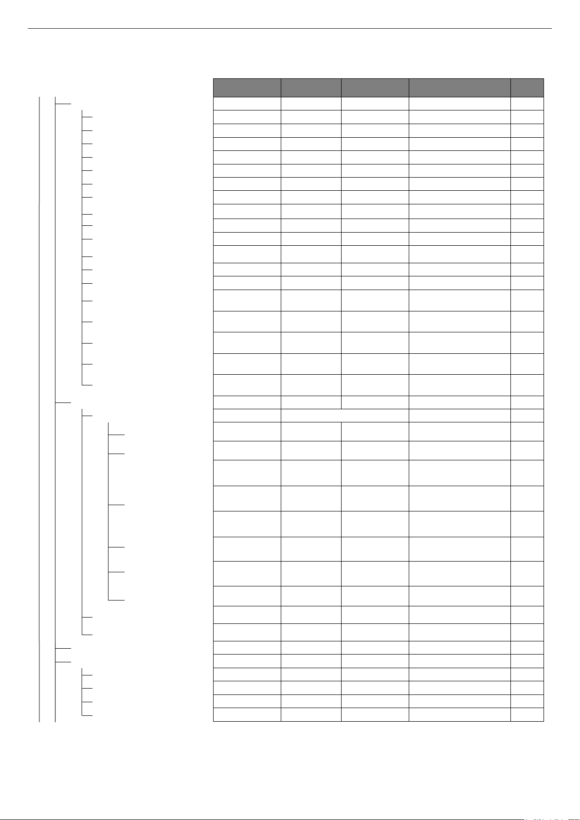
Below is a summary of the MENU tree structure of the REC10.
Some of the information might not be available on the REC10
depending on the access level, the status of the machine or the
system configuration.
LED
Page 9

9
ENGLISH
DEFAULT VALUE
FACTORY SE T
MINIMUM
VALUE
MAXIMUM
VALUE
ACCESS LEVEL
NOTES
SET
VALUE
USER
USER
ITALIANO / EN GLISH
USER
5 min 1 min 15 min USER
USER
USER
Only if POR = 1
USER
Only if POR = 1
USER
Only if POR = 1
USER
USER
INSTALLER
INSTALLER
INSTALLER
MAIN MAIN / ZONE1 / ZON E2
INSTALLER
ITRF05/AKM
ITRF05/AKM
BE16
INSTALLER
Only M AIN zone
THERMOSTAT
THERMOSTAT / TEMPERATURE PROBE /
REC10 MASTER / REC10 SLAVE
INSTALLER
- - 1 6
INSTALLER
Only zones wit h ACTU ATION = BE16
DIRECT ZONE
DIRECT ZONE
MIXING ZONE
INSTALLER
Only zones wit h ACTUATION = BE16
HIGH TEMP.
HIGH TEMP.
LOW TEMP. INSTALLER
40°C (AT)
20°C (BT)
20°C
MAX C H SET INSTALLER
80,5°C ( AT)
45°C (BT)
MIN CH SET
80,5°C ( AT)
45°C (BT)
INSTALLER
INSTALLER
5 0 99
SERVICE
Only mixing z ones with AC TUATION=BE16
10 0 99
SERVICE
Only mixing z ones with AC TUATION=BE16
120 sec
0 sec 240 sec
SERVICE
Only mixing z ones with AC TUATION=BE16
140 sec
0 sec 240 sec
SERVICE
Only mixing z ones with AC TUATION=BE16
55°C
0°C
100°C
SERVICE
Only BT zones with ACTUATION =BE16
0min 0min 240min
SERVICE
Only BT zones with ACTUATION =BE16
2min
VALVE RUN
240min
SERVICE
Only BT zones with ACTUATION =BE16
2min 0min 240min
SERVICE
Only BT zones with ACTUATION =BE16
6°C -20°C 50°C
SERVICE
Only zones wit h ACTU ATION = BE16
5°C 1°C 20°C
SERVICE
Only zones wit h ACTU ATION = BE16
10°C
0°C
100°C
SERVICE
Only zones wit h ACTU ATION = BE16
0 (1 if REC10
in the AMBIENT)
0
1
INSTALLER
INSTALLER
INSTALLER
0,0°C
- 6,0°C 6,0°C
INSTALLER
INSTALLER
MENU
SETTINGS
TIME SCHEDULE
TIME & DATE
LANGUAGE
BACKLIG HT
MAIN
ZONE1
ZONE2
DHW
DHW H EAT PUMP
TECHNI CAL
INSTALLATION
ZONES MANAGER
MODIFY ZONE
ACTUATION TYPE
REQUEST TYPE
BE16 ADDR ESS
HYDRAULIC CONF
ZONE TYPE
MIN CH SET
MAX C H SET
CHANGE NAME
PI - PROPORTIONAL
PI - INTEGRAL
VALVE RUN
CLOSING AT POWER ON
OUTLET OVER
OUTLET OVER TEST TIME
OUTLET OVER WAIT TIME
OUTLET OVER REST TIME
FREEZE PROT TEMP
FREEZE PROT OFFSET ZONE
FREEZE PROT T EXT
POR
ADD ZONE
DELETE ZONE
SENSOR CALIBRATION
SYSTEM RESET
Page 10
10
EXCLUSIVE
DEFAULT VALUE
FACTORY SE T
MINIMUM
VALUE
MAXIMUM
VALUE
ACCESS LEVEL
NOTES
SET
VALUE
INSTALLER
3 min 0 min 20 min INSTALLER
5°C
2°C
10°C
SERVICE
5°C
2°C
10°C
SERVICE
3°C
2°C
10°C
SERVICE
3°C
2°C
10°C
SERVICE
5°C
0°C
10°C
SERVICE
0°C
0°C
6°C
SERVICE
0°C
0°C
10°C
SERVICE
85 41 100 SERVICE
FUNC. NOT ACTIVE
FUNC. NOT ACTIVE
FUNCTI ON ACTIVE
INSTALLER
RELATED
RELATED
ABSOLUTE
INSTALLER
Only in instantaneous confi guration
DEACTIVATE F UNC.
DEACT IVATE FUNC .
ACTIVA TE FUNCTI ON
INSTALLER
0 0 1 SERVICE
6sec 1sec 255sec
SERVICE
If CH DELAY POST- DHW = 1
1 0 1 SERVICE
1 0 1
SERVICE
Only if PRESS TRANSDUCE R = 1
0,6 0,4 1
SERVICE
Only if LOAD ENABLE = 1
0 0 1
INSTALLER
Only if managed by th e contr ol boar d
INSTALLER
MAIN MAIN / ZONE1 / ZON E2
INSTALLER
80,5 °C (AT)
45 °C ( BT)
MIN CH SET
MAX C H SET
INSTALLER
If EXTERNAL PROBE NOT connected
FUNC. NOT ACTIVE
FUNC. NOT ACTIVE
FUNCTI ON ACTIVE
INSTALLER
If EXTERNAL PROBE connected
2,0
1,0
3,0
INSTALLER
If EXTERNAL PROBE connected,
request type TA and z one type AT
0,4
0,2
0,8
INSTALLER
If EXTERNAL PROBE connected,
request type TA and z one type BT
2,0
0,1
5,0
INSTALLER
If request type AMBIENT P ROBE
or REC10
10
0
20
INSTALLER
If request type AMBIENT P ROBE
or REC10
20°C 20°C 40°C
INSTALLER
If request type AMBIENT P ROBE
or REC10
18°C
4°C
20°C
INSTALLER
5min 5min 20min
INSTALLER
Only if EXTERNA L PROBE connected
20 0 255
INSTALLER
Only if EXTERNA L PROBE connected
MAX C H
MIN MAX C H INSTALLER
INSTALLER
see MULTIGAS TABLE
1500 R PM
3000 RPM
INSTALLER
see MULTIGAS TABLE
5500 R PM
9999 R PM
INSTALLER
see MULTIGAS TABLE
MIN MAX INSTALLER
see MULTIGAS TABLE
MIN MAX INSTALLER
PARAMETERS
TIMER OFF CH
HYST ON HIGH T EMP
HYST OF F HIGH TEMP
HYST O N LOW TEMP
HYST OF F LOW TEMP
SP INCR HIGH TEMP
SP INCR LOW TEMP
INCR C OOLING SP
PUMP DUTY CYCLE
RESET TIMER S CH
DHW THERMO STAT
SLIDIN G OUTLET
CH DELAY POST-DHW
CH DELAY TIME
PRESS TRANSDUCER
LOAD ENABLE
START LOADING VALUE
PREHEATING
THERMOREGULATION
CLIMATIC CURVES
FIXED SET POINT
NIGHT COMP
CURVE SLOPE
AMBIENT INFLUENCE
OFFSET
COOLING
RANGE RATED
CALIBRATION
BUILDI NG TYP E
OUTDOOR R EACTIVITY
MIN
MAX
RLA
MAX CH
Page 11

11
ENGLISH
DEFAULT VALUE
FACTORY SE T
MINIMUM
VALUE
MAXIM UM
VALUE
ACCESS LEVEL
NOTES
SET
VALUE
INSTALLER
INSTALLER
INSTALLER
MAX
INSTALLER
RANGE RATED
INSTALLER
MIN
INSTALLER
Current speed
MIN MAX INSTALLER
WEEKLY FUNCTION
F. NOT ACTIVE / DAILY FUNCTION /
WEEKLY FUNCTION
INSTALLER
ENABLE FUN.
ENABLE FUN.
DISABLE FUN. SERVICE
SERVICE
SERVICE
INSTALLER
Only if VENT C YLCE in progress
INSTALLER
INSTALLER
Only in instantaneous confi guration
INSTALLER
INSTALLER
50°C
37,5°C
60°C
INSTALLER
Only if HE AT PUM P enabled to DHW
7°C 0°C 100°C
SERVICE
Only if HE AT PUM P enabled to DHW
5°C 1°C 20°C
SERVICE
Only if HE AT PUM P enabled to DHW
INSTALLER
Only if solar system is not configured
INSTALLER
INSTALLER
60°C 10°C 130°C INSTALLER
8°C
DELTA T OFF
30°C INSTALLER
4°C
4°C
DELTA T ON INSTALLER
0 min 0 min 199 min INSTALLER
(- -)
(- -) / -3 0°C 0°C
INSTALLER
110°C
COLL. T PROT
180°C INSTALLER
110°C 80°C.
T MAX COLL. INSTALLER
40°C
T LOCK 95°C INSTALLER
35°C -20°C
COLL. T AUTH
INSTALLER
0 min 0 min 30 min INSTALLER
FUNC. NOT ACTIVE
FUNC. NOT ACTIVE
FUNCTIO N ACTIVE
INSTALLER
OFF OFF / ON / AU TO
INSTALLER
SWEEP ER
ANTI-LEGIONELLA
VENT C YCLE
ACTIVATE FUN CTIO N
DEACTIVATE FUNCTION
MAX SPEED
RANGE RATED SPEED
MIN SPEED
CHANG E FAN SPEE D
DISABLE FUNCTION
ENABLE FUNCTION
STOP FUNCTION
EXHAUST PROBE RESET
ADD WATER TANK
WATER TANK
ADD SOLAR PLANT
SOLAR
REMOVE WATER TANK
WATER TAN K SETPOINT
TANK FROST PROTECT
TANK FR PROT OFFSET
REMOVE SOLAR PLANT
T MAX TANK
DELTA T ON PUMP
DELTA T OFF PUMP
INTEGRATION DELAY
COLLECTOR T MIN
COLLECTOR T M AX
COLLECTOR T PROT
COLLECTOR T AUTH
COLLECTOR T LOCK
PWM COLL PUMP
TANK C OOLING
SOLAR PUM P STATE
Page 12

12
EXCLUSIVE
DEFAULT VALUE
FACTOR Y SET
MINIMUM
VALUE
MAXIMUM
VALUE
ACCESS LEVEL
NOTES
SET
VALUE
INSTALLER
Only if heat pump not configured
INSTALLER
INSTALLER
Only if heat pump configured
USE BUS
USE BUS
USE FR EE CO NTACTS
SERVICE
DEACTIVATE FUNCTION
FUNCTIO N ACTIVE
DEACTIV ATE FUNCTION
INSTALLER
DHW FUNCTION
NOT ACTIVE
DHW FUNCTION
ACTIVE
DHW FUNCTION
NOT ACTIVE
INSTALLER
1°C
0°C
6°C
SERVICE
DEACTIVATE FUNCTION
FUNCTION ACTIVE
DEACTIV ATE FUNCTION
INSTALLER
100% 50% 100% SERVICE
5°C
-5°C
20°C
INSTALLER
5°C
-5°C
20°C
INSTALLER
-10°C
-20°C
10°C
INSTALLER
30min
1min 240min SERVICE
30min
1min 240min SERVICE
2min 1min 60min SERVICE
2min 1min 60min SERVICE
5°C
0°C
10°C
SERVICE
0h 0h 24h SERVICE
60sec
1sec 300sec SERVICE
AUTO ON AUTO INSTALLER
60°C
20°C
60°C
SERVICE
10°C
0°C
25°C
SERVICE
SERVICE
INSTALLER
DEACTI VATE F.
DEACTI VATE F.
ACTIVATE F.
INSTALLER
INSTALLER
INSTALLER
SERVICE
20°C
15°C
30°C
SERVICE
35°C
30°C
55°C
SERVICE
SERVICE
NG
NG/LPG
SERVICE
A
A/B/C
SERVICE
RESTORE
RESTORE
RESET SERVICE
SERVICE
ADD HEAT PUMP
HEAT PUMP
REMOVE HEAT PUM P
USE FRE E CONTACTS / USE BUS
ENABLE / DISABLE COOLING
USE FO R DHW / DON'T USE FOR DHW
ANTI FR EEZE DELTA SET
ENABLE / DISABLE NIGHT REDUCT
REDUCED FREQUENCY
MIN OUTDOOR TEMP
MIN DHW OUT TE MP
MIN EMERG OUT T
BOILER INTEGR DELAY
HP INTEGR DELAY
BOILER WAITING
HEAT PUMP WAITING
INTEGRATION OFFSET
WINTER SUMMER DELAY
WARNING VALIDATION
ENABLE CIRC STATE ON/ AUTO
DHW H P SETPOINT
DHW O FFSET
ENABLE ALARM HISTORY
ALARM HISTO RY
SCREED HEA TING
COMBUSTION CHECK
SYSTEM INFO
DEACTI VATE FUNCTION
ACTIVATE FUNCTION
FUNCTION S ETTINGS
GAS TYPE
BOILER TYPE
COMBUSTION OFFSET
TFMIN
TFMAX
Page 13

13
ENGLISH
FRI
PLANT
18/05/2013 12:17
MENU
1.3
bar
STATE
30
°C
.3
INFO SET
HOT WATER TEMPERATURE
FRI
MENU
18/11/2013 12:17
SETTINGS
SELECT OPTION
MENU
SETTINGS
TECHNICAL
SELECT OPTION
the level of the tree menu, then press the key
INSERT PASSWORD
00
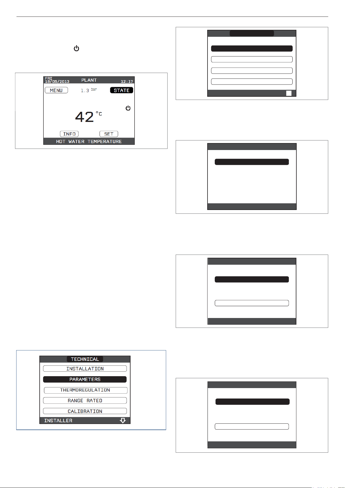
4.1 Access to the technical parameters
Through the REC10 (controller) it is possible to access, using the
TECHNICAL menu, a series of parameters that can be programmed to
allow you to personalise the operation of the boiler:
- Keep the keys and pressed at the same time to enter the
password menu (about 5 sec)
- Using the keys and select the value of the password to
access the INSTALLER or SERVICE authorisation level, depending on
5
-
-
-
-
- select TECHNICAL with the keys and , confirming the
selection with the key
- Access the desired menu and change/view the parameter concerned
(see the menu tree on page 8).
It is possible to return to the start page at any time by keeping the key
“back” pressed for at least 2 seconds.
5.1
Page 14
14
EXCLUSIVE
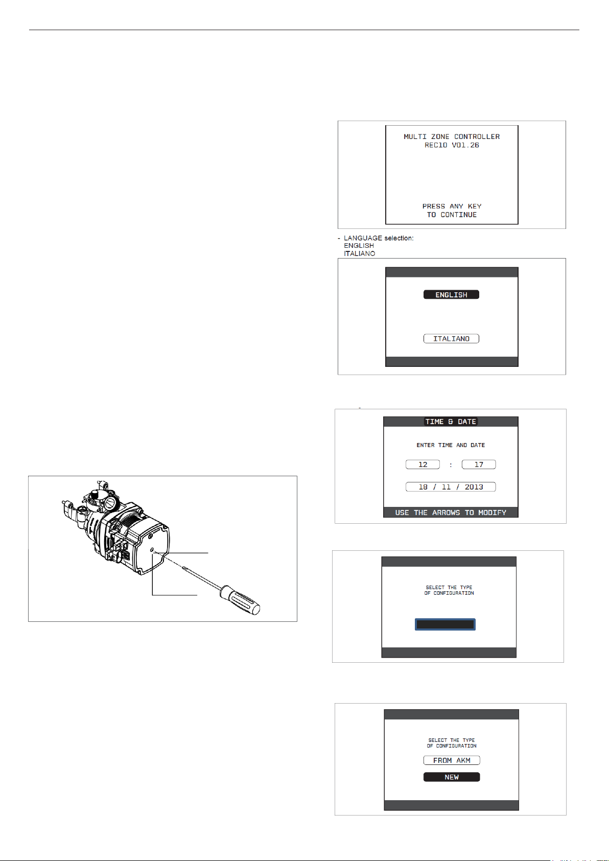
5.2 Initial Programming
At start up the control displays an initial screen
showing the firmware version.
Pressing “ok” a guided procedure is started for configuring
the system; select the desired options with the “up” and
When this screen is presented select FROM AKM and
confirm OK
Set the TIME and DATE confirming each parameter by
pressing ok to confirm
b 1 a
5 COMMISSIONING
5.1 Preliminary checks
First ignition must be performed by a qualified
competent engineer.
Before starting the boiler, check:
- That supply networks (electricity, water, gas) correspond
to the data
- That the flue pipes and air suction pipes are installed correctly
- that spacing conditions for regular maintenance are
guaranteed if the boiler is placed inside or between items
of furniture
- The Gas system is sound
- That the fuel flow rate corresponds to values required by the
boiler
- That the fuel supply system is sized to provide the correct
low rate to the boiler, and that it has all the safety and
control devices required
- That the circulator rotates freely because, occasionally
from new or after a long period of dormancy the impeller
can stick. See below
Releasing of the circulating pump shaft
- Insert a screwdriver in hole (1) of the circulator.
- Press (a) and turn with Phillips screwdriver (b) to release
the pump shaft
Perform this operation with caution to avoid damaging components.
SLAVE
MASTER
Select MASTER from the next screen and ok to confirm
Page 15
15
ENGLISH
TIMER OFF CH
3
MIN
TIMER OFF CH
RESET TIMERS CH
DHW THERMOSTAT
PREHEATING
FRI
PLANT
18/05/2013 12:17
MENU
1.3
bar
STATE
42
°C
INFO SET
HOT WATER TEMPERATURE
INSTALLER
RESET TIMERS CH
FUNCTION NOT ACTIVE
FUNCTION ACTIVE
INSTALLER
DHW THERMOSTAT
RELATED
ABSOLUTE
INSTALLER
Each time that the boiler is powered an automatic venting
cycle is carried out lasting 2 min. To interrupt the vent
cycle, carry out the procedure explained in the section
“5.3 First commissioning”.
- Set the boiler to OFF from REC10 selecting the STATE
menu and then BOILER.
Through the control it is possible to access using
the TECHNICAL menu a series of parameters
that can be programmed allowing you to
personalize the operation of this appliance based
on the type of system to which it is attached.
set parameters according to the desired operating mode
CUSTOMISATION
Configuring the boiler to suit the system
- TIMER OFF CH
This parameter allows you to change the TIMER OFF CH, regarding
the delay time introduced for re-igniting the burner in the face of an off
due to the heating temperature being reached. The factory setting for
this parameter is 3 minutes and can be set to a value between 0 min
and 20 min selecting as desired with the “up” and “down”, keys
confirming the selection.
In all cases at least step 5.2.1 must be followed
5.2.1
Typical Boiler configuration
- Access the technical parameters as explained in the section “4.1 Access
to the technical parameters”.
- With the “up” and “down” keys select PARAMETERS, confirming the
selection.
- Select from among the following options with the “up” and “down”,
keys, confirming the selection.
- RESET TIMERS CH
This parameter allows you to reset the REDUCED HEATING MAXIMUM
OUTPUT TIMING, during which the speed of the fan is limited to 75%
of the maximum heating output that has been set, and the TIMER OFF
CH. The factory setting for this parameter is FUNCTION NON ACTIVE,
select FUNCTION ACTIVE using the keys “up” and “down”, confirming
the selection for resetting the timings.
- DOMESTIC HOT WATER THERMOSTAT
This parameter allows you to set the type of DOMESTIC HOT WATER
THERMOSTAT.
The factory setting for this parameter is RELATED, i.e. for domestic hot
water the boiler switches off at set point +5°C and restarts at set point
+4°C.
To select the ABSOLUTE values, where the boiler for domestic hot water
will still switch off at 65°C and restart at 63°C, use the keys “up” and
“down”.
Page 16

16
EXCLUSIVE
PREHEATING
0
TECHNICAL
INSTALLATION
PARAMETERS
THERMOREGULATION
RANGE RATED
CALIBRATION
INSTALLER
INSTALL
ZONES MANAGER
SENSOR CALIBRATION
SYSTEM RESET
INSTALLER
INSTALL
MAIN
INSTALLER
INSTALL
MODIFY ZONE
ADD ZONE
DELETE ZONE
INSTALLER
MFORNI
18/05/2013
PLANT
12:17
MENU
1.3
bar
STATE
30
°C
.3
INFO SET
HOT WATER TEMPERATURE
- PREHEATING DHW FUNCTION
Setting PREHEATING = 1 the boiler’s domestic hot water function
activates. This function keeps the water in the domestic hot water
exchanger hot, to reduce standby times when a request is made. When
the preheating function is enabled the symbol P comes on with a steady
light at the top with respect to the hot water icon. During burner ignition
following a preheating request, the symbol P starts flashing.
To deactivate preheating function, set parameter to PREHEATING= 0,
the symbol P switches off.
The function is not active when the boiler is OFF.
At this point a standard radiator system is configured
move to section 53 First Commissioning P 17/18
5.2.2 Configuration of the zone
It is possible to customize the management of the heating zone by
accessing the ZONES MANAGER menu.
- Access the technical parameters as explained in the section “4.1
Access to the technical parameters”.
- In sequence select INSTALLATION, ZONES MANAGER and MODIFY
ZONE with the “up” and “down” keys, confirming the selection.
- Select the desired heating zone and then choose from among the options
with the “up” and “down” keys, confirming the selection:
- TYPE OF ACTUATION
Set the parameter in question to ITRF05/AKM (default value)
- TYPE OF HEAT REQUEST
This parameter allows you to specify the type of heat request, it is
possible to choose from the following options:
THERMOSTAT (factory default): the heat request is generated with an
ON/OFF thermostat
REC10 MASTER: the heat request is generated by the REC10
MASTER; in this case the REC10 assumes the function of BOILER
INTERFACE
- TYPE OF ZONE
This parameter allows you to specify the type of zone to be heated, it
is possible to choose from the following options:
HIGH TEMPERATURE (factory default):
LOW TEMPERATURE
- MIN SET HEAT
This parameter allows you to specify the minimum heating set point
possible - range 20°C - 80.5°C, default 40°C for high temp systems
or a range 20°C - 45°C, default 20°C for low temperature systems)
- MAX SET HEAT
This parameter allows you to specify the maximum heating set point
possible -range 20°C - 80.5°C, default 80.5°C for high temp systems
or a range 20°C - 45°C, default 45°C for low temperature systems)
- CHANGING NAME
Allows you to attribute a specific name to the heating zone
- POR Allows you to enable the heating programming timing for
the zone concerned if the heat request is carried out using a
room thermostat
Time schedule not enabled = 0
When the room thermostat contact closes the heat request is always
met without any boiler set time band limitation
Time schedule enabled = 1
When the room thermostat contact closes the heat request is enabled
according to the boilers programmed timing.
Note: in this case make sure that the operating mode of the zone is set
to AUTO in the STATE menu.
5.2.3 Time band schedule function (room thermostat)
Whenever the heating system is managed by a room thermostat without
any time schedule feature, it is possible to tie the heat requests coming
from the device to programmable time bands by setting the parameter
POR = 1 (see section “5.2.2 Configuration of the zone”), in other cases it is
always enabled.
To access this function:
- select MENU on the main page of the REC10 and press “ok”
Page 17

17
ENGLISH
MAIN
START END
SELECT
A DAY
THURSDAY
ZONE SCHEDULE
07:30 08:30
11:30 13:30
18:00 22:30
INSTALLATION
PARAMETERS
THERMOREGULATION
RANGE RATED
CALIBRATION
MENU
SETTINGS
TIME SCHEDULE
SELECT OPTION
MON
SCHEDULE
18/11/2013 12:17
MAIN
SELECT THE ZONE
TECHNICAL
INSTALLER
- Using the “up” and “down” keys select TIME SCHEDULE confirming
the selection
-
From this menu it is possible to access the display and adjustment of the
programme timing for the heating functions of the zone. For each day of
the week it is possible to set up to 4 bands, with a start time and end time.
Note: for more details for the use of the programme timing see the USER
MANUAL section.
5.2.4 Setting up thermoregulation (Weather compensation)
Thermoregulation only works with an outdoor temperature sensor is
connected and is active only for the HEATING function; - connect the
outdoor temperature sensor to the specific connections on the boiler
terminal board.
This enables use of the THERMOREGULATION function.
The temperature measured by the outdoor temperature sensor is displayed
on screen in the top right, alternating with the display of the time. When
thermoregulation is enabled the algorithm for automatically calculating the
outlet set point depends on the type of heat request.
In any case, the thermoregulation algorithm will not directly use the outdoor
temperature, but rather a calculated outdoor temperature that takes into
account the building’s insulation: in well insulated buildings, the outdoor
temperature variations will have less impact than those that are poorly
insulated.
Enabling THERMOREGULATION occurs in the following way:
- Access the technical parameters as explained in section “4.1 Access to
the technical parameters”
- Select THERMOREGULATION with the “up” and “down” keys,
confirming the selection.
Then Using the control it is possible to set values of the following parameters:
BUILDING TYPE
This is indicative of the frequency with which the value of the calculated
outdoor temperature for thermoregulation is updated, a low value for this
will be used for buildings with little insulation.
Setting range: [5min - 20min]
Factory default: [5min]
REACTIVITY EXT SENSOR
This is an indication of the speed with which variations of the measured
outdoor temperature affect the calculated outdoor temperature value for
thermoregulation, low values indicate high speeds.
Setting range: [0 - 255]
Factory default: [20]
To change the value of the above parameters proceed as described
- Access technical parameters as explained in the section “4.1 Access to
the technical parameters”
- In sequence select THERMOREGULATION and TYPE OF BUILDING
with the “up” and “down” keys, set & confirm the selection
Note: The value of the calculated outdoor temperature used by the
thermoregulation algorithm is displayed in the INFO menu under TEXT
FOR THERMOREG.
HEAT REQUEST FROM THERMOSTAT or POR (Programmable Timer)
In this case the outlet set point depends on the outdoor temperature for
obtaining a reference ambient temperature of 20°C. There are 2 parameters
that compete to calculate the output set point:
- Slope of the compensation curve (KT)
- Offset on the reference ambient temperature.
SELECTING THE COMPENSATION CURVE- fig. 17
The compensation curve for heating maintains a theoretical temperature of
20°C indoors, when the outdoor temperature is between +20°C and -20°C.
The choice of the curve depends on the minimum outdoor temperature
envisaged (and therefore on the geographical location), and on the delivery
temperature envisaged (and therefore on the type of system). It is carefully
calculated by the installer on the basis of the following formula:
KT = T. outlet envisaged – T shift
20- min. design external T
T shift = 30°C standard system
25°C floor installations
If the calculation produces an intermediate value between two curves, you
are advised to choose the compensation curve nearest the value obtained.
Example: if the value obtained from the calculation is 1.3, this is between
curve 1 and curve 1.5. Choose the nearest curve, i.e. 1.5.
The settable KT values are as follows:
Standard system: 1.0-3.0
Floor system 0.2-0.8.
Using the screen it is possible to set the selected thermoregulation curve:
- Access technical parameters as explained in the section “4.1 Access to
technical parameters”
- In sequence select THERMOREGULATION and then CLIMATIC CURVES
- Select the desired heating zone with the “up” and “down” keys,
confirming the selection
- Set the desired climatic curve with the “up” and “down” keys, confirming
the selection.
-
OFFSET ON THE REFERENCE AMBIENT TEMPERATURE - fig. 17
In any event, user action can indirectly modify the value of the HEATING
set point inserting an offset on the reference temperature that can vary
within the range -5-+5 (offset 0 = 20°C).
NIGHT COMPENSATION - fig. 17
Whenever a programmable timer is connected to the ROOM THERMOSTAT
input, from the TECHNICAL\THERMOREGULATION\CLIMATIC CURVES\
MAIN the NIGHT COMPENSATION function can be enabled.
In this case, when the CONTACT is CLOSED, the heat request is made
by the flow sensor, on the basis of the outdoor temperature, to obtain a
nominal ambient temperature on DAY level (20°C).
Opening of the contact does not produce a switch-off, but a reduction
(parallel translation) of the climatic curve on NIGHT level (16°C).
in this case, the user can indirectly modify the value of the HEATING set
point inserting once again an offset on the reference DAY temperature
(20°C) rather than NIGHT (16°C) that can vary within the range [-5 - +5].
5.3 First commissioning ; See Over
Page 18

18
EXCLUSIVE
FRI
PLANT
18/05/2013 12:17
MENU
1.3
bar
STATE
42
°C
INFO SET
HOT WATER TEMPERATURE
STATE
BOILER
MAIN ZONE
BOILER
OFF
SUMMER
WINTER
TECHNICAL
THERMOREGULATION
RANGE RATED
CALIBRATION
SWEEPER
VENT CYCLE
INSTALLER
VENT CYCLE
STOP FUNCTION
INSTALLER
FRI
PLANT
18/05/2013 12:17
MENU
1.3
bar
STATE
30
°C
.3
INFO SET
HOT WATER TEMPERATURE
BOILER
OFF
SUMMER
WINTER
combustion analysis button SW1
X6
X3 X7
1 3 1
SW1
6
1
5
1
X14 X17
- 5.3 FIRST COMMISIONING
- \With Gas on and power on
- First set the room thermostat to the desired temperature (say 20°C)
Then set the boiler for WINTER (heat on) by first selecting the STATE
menu on the screen and then BOILER, - WINTER
-
The vent cycle can be interrupted by removing the cap from the rear of
the instrument panel and pressing the combustion analysis button
SW1 or else from the TECHNICAL menu of the control in the
following way:
- access the technical parameters as explained in section “4.1 Access to
technical parameters”
- with the “up” and “down” keys, select VENT CYCLE confirming the
selection
- With the “up” and “down” keys, select STOP FUNCTION confirming
the selection.
- When there is a heat request and the boiler is igniting, the icon
“ ” appears on the display. The boiler will start up and continue working
until the set temperatures are reached, after which it will then go back
to standby.
Each time the boiler is started up an automatic venting cycle is
carried out lasting 2 min. When the vent cycle is in progress, all heat
requests are inhibited and a sliding message at the foot of the page
appears on the main page of the screen.
In this condition the green and red LEDs light up alternately for 0.1
sec with a pause of 0.5 sec and 1 sec between one ignition and
another.
The screen will briefly display a wait message after which you will
automatically be taken to the main screen.
SUMMER : selecting STATE - BOILER and then SUMMER, the function
of just domestic hot water will be activated. In this mode the screen
normally displays the temperature of the domestic hot water supplied by
the boiler.
WINTER / : selecting STATE - BOILER and then SUMMER
heating and domestic hot water functions are activated. The screen
normally displays the domestic hot water temperature unless there is a
heating request in progress, in which case the boiler’s outlet temperature
is displayed.
the
Page 19

19
ENGLISH
The display shows “ ” to indicate the presence of a flame.
SET
HEATING
DHW
PREHEATING
SET
HEATING
DHW
PREHEATING
FRI
PLANT
18/05/2013 12:17
MENU
1.3
bar
STATE
42
°C
INFO SET
HOT WATER TEMPERATURE
E010
FLAME LOCKOUT
PRESS OK RESET
SET
HEATING
DHW
PREHEATING
5.4 Adjusting the heating output temperature
without an outdoor temperature sensor
When there is no outdoor temperature sensor, the boiler operates at
a fixed-point, the HEATING set point in this case can be set selecting
SET on the main screen and selecting the desired value within the range
[40°C - 80.5°C] for high temperature systems or [20°C - 45 °C] for low
temperature systems.
To deactivate the preheating function, set the parameter to PREHEATING = 0,
the symbol “P” switches off.
The function is not active when the boiler is OFF.
5.8 Boiler ignition fails
If the boiler fires correctly
5.5 Adjusting heating output temperature with an
outdoor temperature sensor connected
When an outdoor temperature sensor is installed, the outlet temperature
is automatically selected by the system, which quickly adjusts the ambient
temperature according to variations in the outdoor temperature. If you
want to change the temperature, raising it or lowering it with respect to that
automatically calculated by the electronic board, it is possible to change the
HEATING set point by selecting SET on the main screen and selecting
within the range (-5 - +5) the desired comfort level (see section “5.2.4
Setting the thermoregulation”).
Note: when there is an outdoor temperature sensor connected it is still
possible to have the boiler operate at a fixed point setting the values of MIN
SP HEAT and MAX SP HEAT at the desired HEATING set point.
5.6 Adjustment of domestic hot water
temperature
To adjust the domestic hot water temperature set the Domestic hot water
set point by selecting SET - DHW on the main screen and selecting the
desired value within the range [37.5°C - 60°C].
5.7 “Preheating DHW ” function
Please refer to section 5.2.1 PREHEATING DHW on P16
The boiler will be in operation until the selected temperature is reached,
afterwards it will be in “standby” again keeping the outlet temperature
displayed.
Ignition faults , during Start up ( or operation,)
The boiler performs a “SAFETY STOP”: the triangle signaling faults will
lash on the screen. To identify the fault codes and to reset the boiler,
see section “5.15 Faults and fault lights”.
5.9 Reset function
In the event of a lockout, it is possible to try and restore the normal operation
of the appliance by pressing the “ok” key on the screen when the fault
message is displayed for resetting the alarm presented.
If the reset attempts do not restart the boiler, contact your service contractor
Page 20

20
EXCLUSIVE
TECHNICAL
RANGE RATED
CALIBRATION
SWEEPER
EXHAUST PROBE RESET
SCREED HEATING
INSTALLER
BOILER
DAY
TIME
TEMPERATURE
1 0 20°C
6
22°C
12
24°C
18
26°C
2 0 28°C
12
30°C
3 0 32°C
4 0 35°C
5 0 35°C
6 0 30°C
7 0 25°C
BOILER
OFF
SUMMER
WINTER
SCREED HEATING
DEACTIVATE FUNCTION
ACTIVATE FUNCTION
INSTALLER
TECHNICAL
PARAMETERS
VENT CYCLE
EXHAUST PROBE RESET
ALARM HISTORY
COMBUSTION CHECK
SERVICE COMBUSTION CHECK
GAS TYPE
BOILER TYPE
COMBUSTION OFFSET
SERVICE
5.10 Underfloor heating : conditioning function
For Underfloor systems this boiler has a system conditioning function for
bedding in the system in a (New ) floor - Screed Heating - as follows
- set the status of the boiler to OFF
- Access technical parameters as explained in section “4.1 Access to
technical parameters”
- With the “up” and “down” keys select SCREED HEATING, confirming
the selection by pressing OK (note: SCREED HEATING is not available
if the boiler is not OFF)
5.11 Checks during and after the first commissioning
After starting up, check that the boiler carries out the start-up procedures
and subsequent shut-down properly.
Check the domestic hot water operation by opening a hot water tap in
SUMMER or WINTER mode.
Check the full stop of the boiler by turning off the system’s main switch.
After a couple of minutes of continuous operation to be obtained by turning
the system’s main switch to “ON”, setting the boiler mode selector to
SUMMER and by keeping open the domestic hot water device, the binders
and manufacturing waste evaporate and it will be possible to carry out:
- Checking of the combustion.
- Then with the “up” and “down” select ACTIVATE FUNCTION and
confirm the selection to activate the function
- To stop use “up” and “down” to select DEACTIVATE FUNCTION and
confirm the selection with ok to deactivate the function.
The screed heating function, when active, is signaled by the scrolling
message at the bottom of the screen, SCREED HEATING FUNCTION IN
PROGRESS - OUTLET TEMPERATURE, while on the
electronic board the red and green LEDs flash alternately with a frequency
of 1 sec ON - 1 sec OFF.
The “screed heating” function lasts 168 hours (7 days) during which, in
the zones configured as low temperature, a heating request is simulated
with an initial zone outlet of 20°C, then increased in line with the table.
Accessing the INFO menu from the main screen it is possible to display
the TIME FUNC SCREED HEATING value regarding the number of hours
since the start of the function.
Once activated, the function takes priority, if the appliance is shut down by
disconnecting the power supply, when it is restarted the function picks up
from where it was interrupted.
The function can be interrupted before its end by putting the appliance into
a condition other than OFF or else by selecting DEACTIVATE FUNCTION
from the relative menu.
Note: The temperature and increase values can be set to different values
only by qualified personnel, only if strictly necessary. The manufacturer
declines all responsibility if the parameters are incorrectly set.
5.12 Gas conversion for LPG
It is easy to convert from one gas family to another even after the boiler
has been installed. This operation must be performed by professionally
competent engineers only
The boiler is default set to work with natural Gas (G20). To convert the
boiler to LPG (G31) proceed as follows:
- Access technical parameters as explained in section “4.1 Access to
technical parameters”
- Set the password for SERVICE
- Select COMBUSTION CHECK using the “up” and “down” keys,
confirming the selection with ok
- Now select GAS TYPE
Page 21

21
ENGLISH
GAS TYPE
NG
LPG
SERVICE
TECHNICAL
PARAMETERS
THERMOREGULATION
RANGE RATED
CALIBRATION
SWEEPER
INSTALLER
SWEEPER
ACTIVATE FUNCTION
INSTALLER
combustion analysis button SW1
SW1
6
1
X17
TECHNICAL
INSTALLATION
PARAMETERS
THERMOREGULATION
RANGE RATED
CALIBRATION
INSTALLER
- select LPG
The boiler DOES NOT require additional adjustments.
The boiler may only be converted by qualified engineers.
After conversion apply the new rating plate contained in the kit.
5.13 Combustion check
To carry out the combustion analysis, proceed as follows:
- power the boiler electrically by setting the main system switch to “ON”
set the status of the boiler to OFF
-
- access the technical parameters as explained in the section “4.1 Access
to the technical parameters”
- select SWEEPER with the “up” and “down” keys, confirming the
selection
- select ACTIVATE FUNCTION with the “up” and “down” keys, confirming
the selection.
Wait for the burner to ignite.
The boiler will operate at maximum heating output and it will be possible to
regulate the combustion.
- Insert the analyser probe in the specific position on the air distribution box,
after removing screw (A) and cap of the flue gases analysis socket (B).
- Check the combustion readings verifying that the CO2 values
correspond to those indicated in the multigas table.
- Once the check is completed, remove the analyser probe and close the
combustion analysis sockets with appropriate caps and screw.
If the value displayed is different DO NOT MAKE ANY
ADJUSTMENT OF THE GAS VALVE, please contact Heat IQ (NZ)
for technical assistance
The gas valve DOES NOT requires adjustments it is possible
Tampering will cause further causes a malfunction or failure.
When the sweeper function is in progress all heat requests are
inhibited and a scrolling message appears at the foot of the main
screen; - the green and red LEDs are off.
A
B
When the checks are completed:
- Set the boiler to “SUMMER” or “WINTER” mode as required
- Regulate the heat request temperature values according to the
customer’s needs.
IMPORTANT
The sweeper function is active for a time limit of 15 minutes; the burner
shuts down if an outlet temperature of 95° C is reached. It will ignite again
when the temperature falls below 75° C.
In case of a low temperature system we recommend carrying out
the efficiency test by setting the boiler STATE to SUMMER, opening
the hot water tap to full capacity and setting the temperature of the
domestic hot water to the maximum.
All Testing must be carried out by a qualified engineer
- Note: the sweeper function can also be activated by pressing the
SW1 key on the electronic board AKM01 (this requires removing the
plug (C) from the cover of the instrument panel to access the electrical
components).
5.14 Range rating
This boiler can be adapted to the systems thermal requirements as it is
possible to set the maximum flow rate for the boiler operation in heating
mode:
- Power on the boiler
- Access parameters as explained in paragraph “4.1 Access to technical
parameters”
- Select RANGE RATED and confirm it
Page 22

22
EXCLUSIVE
RANGE RATED
5100
RPM
EXCLUSIVE 30C
HTG curve (Qnheating)
8400
8000
7600
7200
6800
6400
6000
5600
5200
4800
4000
3600
3200
2800
2400
2000
1600
1200
800
2 4 6 8 10 12 14 16 18 20 22 24 26 28 30
Heat output (kW)
CO s.a. curve (Qnh eating)
160
150
140
130
120
110
100
90
80
70
60
50
40
30
20
10
0
0 2 4 6 8 10 12 14 16 18 20 22 24 26 28 30 32
Heat output (kW)
EXCLUSIVE 35C
HTG curve (Qnheating)
8400
8000
7600
7200
6800
6400
6000
5600
5200
4800
4400
4000
3600
3200
2800
2400
2000
1600
1200
800
2 4 6 8 10 12 14 16 18 20 22 24 26 28 30 32 34 36
Heat output (kW)
CO s.a. curve (Qnheating)
180
170
160
150
140
130
120
110
100
90
80
70
60
50
40
30
20
10
0
0 2 4 6 8 10 12 14 16 18 20 22 24 2 6 28 30 3 2 34 36
Heat output (kW)
CO emissions s.a. (p.p.m.)
Fan rotations (rpm) Fan rotations (rpm)
CO emissions s.a. (p.p.m.)
CO emissions s.a. (p.p.m.) Fan rotations (rpm)
EXCLUSIVE 25C
HTG curve (Qnheating)
8400
8000
7600
7200
6800
6400
6000
5600
5200
4800
4400
4000
3600
3200
2800
2400
2000
1600
1200
800
2 4 6 8 10
12 14 16 18 20
22
24
26
28
30
Heat output (kW)
CO s.a. curve (Qnheating)
240
230
220
210
200
190
180
170
160
150
140
130
120
110
100
90
80
70
60
50
40
30
20
10
0
2 4 6 8 10 12 14 16 18 20
22 24 26 28 30
Heat output (kW)
- Set the desired heating maximum value (rpm) with the “up” and “down”
keys, confirming the selection
- Once the desired power is set (maximum heating) note the value onto the
supplied self-adhesive label for the guidance of future engineers who
can refer to the set value posted.
The calibration does not cause the boiler ignition.
NOTE
RANGE RATING IS ONLY REQUIRED IN EXCEPTIONAL CIRCUMSTANCES
The boiler is supplied with the settings indicated in the multigas table.
It is nevertheless possible, according to the system requirements or the
regional regulations on the combustion gas emission limits, to set that value
by referring to the graphs below.
Page 23

23
ENGLISH
FRI
PLANT
18/05/2013 12:17
MENU
1.3
bar
STATE
42
°C
INFO SET
HOT WATER TEMPERATURE
E020
LIMIT THERMOSTAT
REC10 ATTEMPTS EXHAUSTED
E041
WATER TRANSDUCER
PRESS OK TO LOAD THE PLANT
TECHNICAL
THERMOREGULATION
RANGE RATED
CALIBRATION
SWEEPER
EXHAUST PROBE RESET
INSTALLER
THE PARAMETER
WILL BE CHANGED
CONFIRM CANCEL
CONFIRM OR DELETE
SELECTION
FRI
PLANT
18/05/2013 12:17
MENU
1.3
bar
STATE
30
°C
.3
INFO SET
HOT WATER TEMPERATURE
A
5.15 ALARMS AND FAULT LIGHTS
If any faults should occur, a screen will appear on the display indicating
the relative error code and a brief alphanumeric description of the same.
Pressing the “back” button it is possible to return to the main screen,
a fault is signaled by this lashing icon .
The user can return to the fault description screen by using the “up” and
“down” keys and then pressing the “ok” key.
The faults description screen is automatically displayed once the display
illumination time has elapsed without any button being pressed.
Press the “up” and “down” keys to display the descriptions of any other
faults that may be present.
Reset function
In order to reset the boiler’s operation in the event of a fault, it is necessary
to access the fault description screen. If the lockout is of a non-volatile type
that requires a reset procedure, this will be indicated on the screen, and
can be performed by pressing the “ok” button on the control
At this point, if the correct operating conditions have been restored, the
boiler will restart automatically.
There is a maximum of 5 consecutive attempts at a release by the fault,
when used up it is possible to unlock the boiler by cutting off and
reconnecting the electrical power supply.
When the boiler has fault E040 manual loading should be carried out using
the filler tap (A) until the pressure is between 1 and 1.5 bar.
If the pressure drops frequently, contact the installer or competent
service engineer
For fault E060
Boiler is working normally, but does not provide any stability of domestic
hot water temperature that, in any event, is supplied at a temperature of
around 50°C. Then a service engineer is required
For fault E091
The boiler has an auto-diagnostic system which, based on the total number
of hours in certain operating conditions, can signal the need to clean the
primary exchanger (alarm code E091).
Once the cleaning operation has been completed, reset to zero the total
hour meter with special kit supplied as an accessory following procedure
indicated below:
- Access technical parameters as explained in section “4.1 Access to
technical parameters”
- Select EXHAUST PROBE RESET with the “up” and “down” keys,
confirming the selection
If attempts to reset the boiler fail, contact the installer service agent
For fault E041
If the pressure drops below the safety pressured of 0.3 bar the boiler
displays the fault code “E041 - WATER TRANSDUCER PRESS OK TO FILL
THE SYSTEM” for a transitional time of 10 min during which it is possible
to start the semi-automatic loading procedure, pressing the “ok” key to f
the system (the procedure can only be started in SUMMER or WINTER mode).
During the loading phase the scrolling message appears on the foot of the
page “SEMI-AUTOMATIC FILLING IN PROGRESS”, the green and red LEDs
flash, while the pressure shown on the display should start to rise.
When the loading is finished the scrolling message “SEMI-AUTOMATIC
FILLING FINISHED” is displayed at the foot of the page and the green and
red LEDs come on fixed for about 4 seconds.
When the transitional time has finished, if the fault persists the fault code
E040 is displayed.
- Select CONFIRM to confirm the rest of the flue gases probe meter or else
CANCEL to cancel the operation
ill
Note: the meter resetting procedure should be carried out after each indepth cleaning of the primary exchanger or if it is replaced.
The total hours can be verified in the following way:
- select INFO on the initial screen and press “ok”
- With the “up” and “down” keys select EXHAUST PROBE RESET and
press “ok” to display the hours value of the meter.
Page 24

24
EXCLUSIVE
ERROR
CODE
ERROR MESSAGE
RED LED
GREEN LED
DESCRIPTION OF TYPE
OF ALARM
E010
flame lockout/ACF electronic fault
ON
definitive
E011
extraneous flame
flashing
0.2 sec. on/0.2 off
transitional
E020
limit thermostat
flashing
0.5 sec. on/0.5 off
definitive
E030
fan fault
ON
definitive
E040
water transducer – load system
ON
ON
definitive
E041
water transducer - press OK to ill
the system
flashing
0.5 sec. on/0.5 off
transitional
E042
water pressure transducer fault
ON
ON
definitive
E060
domestic hot water probe fault
flashing
0.5 sec. on/0.5 off
flashing
0.5 sec. on/0.5 off
transitional
E070
fault low sensor/over temperature low sensor
low/return sensor differential alarm
ON
transitional/definitive
definitive
E077
main zone water thermostat
ON
transitional
E080
fault return line probe/return line probe over temperature/
outlet/return line probe differential alarm
ON
transitional/definitive/
definitive
E090
fault flue gases probe
flue gases over temperature probe
flashing
0.5 sec. on/0.5 off
flashing
0.5 sec. on/0.5 off
transitional
definitive
E091
clean primary heat exchanger
flashing
0.5 sec. on/0.5 off
flashing
0.5 sec. on/0.5 off
transitional
--
water pressure low press OK to charge
flashing
0.5 sec. on/0.5 off
transitional
--
water pressure high check system
flashing
0.5 sec. on/0.5 off
transitional
--
boiler board communication lost
ON
flashing
0.5 sec. on/0.5 off
transitional
--
BUS 485 communication lost
ON
flashing
0.5 sec. on/0.5 off
transitional
ERROR
CODE
ERROR MESSAGE
LED
RED
LED
GREEN
DESCRIPTION OF TYPE OF ALARM
E021
iono alarm
ON
These are temporary alarms that if they occur 6 times in an hour they
become definitive; the alarm E097 is displayed and is followed by
post-
purging for 45 seconds at the fan’s maximum speed.
It is not possible to release the alarm before the end of the post-purging
unless the boiler’s power supply is switched off.
E022
iono alarm
ON
E023
iono alarm
ON
E024
iono alarm
ON
E067
iono alarm
ON
E088
iono alarm
ON
E097
iono alarm
ON
E085 incomplete combustion
ON
These are temporary alarms that if they occur 3 times in an hour they
become definitive; the last error to occur is displayed and is followed by
a
post-purging of 5 minutes at the fan’s maximum speed.
It is not possible to release the alarm before the end of the post-purging
unless the boiler’s power supply is switched off.
E094 incomplete combustion
ON
E095 incomplete combustion
ON
E058
mains voltage fault
ON
These are temporary faults that restrict the ignition cycle.
E065 current modulation alarm
ON
E086 obstruction fumes alarm
ON
Temporary fault reported during the post ventilation. It is maintained a post
ventilation of 5 min at maximum fan speed.
BOILER STATUS
RED LED
GREEN LED
NOTES
Power-on
lashing 0.5 sec. on/0.5 off
flashing
0.5 sec. on/0.5 sec. off
The red and green LEDs come on at the same time
Vent cycle
flashing
0.5 sec. on/1 sec. off
flashing
0.5 sec. on/1 sec. off
The red and green LEDs come sequentially one at a time
OFF status
flashing
0.3 sec. on/0.5 sec. off
No heat request (stby)
flashing
0.3 sec. on/0.5 sec. off
Transitional ignition/over temperature
flashing
0.3 sec. on/0.5 sec. off
Presence of lame
ON Chimney sweep
fixed
Only if the lame is present
Screed heater
flashing
1 sec.on/1 sec. off
flashing
1 sec.on/1 sec. off
The red and green LEDs come on alternately
Semi-automatic filling in progress
flashing
0.5 sec. on/1 sec. off
flashing
0.5 sec. on/1 sec. off
The red and green LEDs come sequentially one at a time
Semi-automatic filling finished
ON
ON
The red and green LEDs are on and f ixed and at the same time
for about 4 sec
Boiler faults list
List of combustion faults
Warning lights
Page 25

25
ENGLISH
INSTALLATION
PARAMETERS
THERMOREGULATION
RANGE RATED
CALIBRATION
TECHNICAL
RANGE RATED
CALIBRATION
SWEEPER
EXHAUST PROBE RESET
ALARM HISTORY
INSTALLER
1 - 10:30 18/11/2013
E030
FAN ANOMALY
USE ARROW KEYS
TO SEE OTHER ANOMALIES
BOILER
OFF
SUMMER
WINTER
BOILER
OFF
SUMMER
WINTER
TECHNICAL
INSTALLER
Closing
position
5.16 Alarm history
The ALARM HISTORY function is automatically enabled only after the
machine has been powered up for at least 2 consecutive hours, during
this period any alarms that arise would not be saved in the “alarm history”.
Alarms are displayed in chronological order, from the most recent to the
oldest, up to a maximum of 5 alarms; to display the alarm history:
- access technical parameters as explained in section “4.1 Access to
technical parameters”
- select ALARM HISTORY with the “up” and “down” keys, confirming
the selection
- Scroll through the alarm history with the “up” and “down” keys; for
each alarm a sequential number is displayed, an error code and the date
and time the alarm occurred.
- Domestic hot water anti-freeze:
Starts if the temperature measured by the DHW NTC probe falls below
5°C. A heat request is generated in this phase with the ignition of the
burner at minimum output, which is maintained until the outlet water
temperature reaches 55° C.
Activation of the ANTI-FREEZE function is indicated by a
scrolling message on the foot of the display.
- circulator anti-locking: the circulator activates after every 24 hours of
stoppage for 30 seconds.
-
5.18 Switching off for lengthy periods
If the boiler is not used for an exceptionally long time, the following
operations should be carried out:
- Set the status of the boiler to OFF
- Set the system’s main switch to “off”
- Close the Gas and water taps of the heating and domestic hot water
system.
In this case, the anti-freeze and anti-blocking systems are deactivated.
Drain the heating and domestic water system if there is any risk of freezing.
It is possible to return to the start page at any time by keeping the key
“back” pressed for at least 2 seconds.
Note: once enabled, the ALARM HISTORY function can no longer be
disabled; there is no procedure for resetting the alarm history.
If an alarm repeats consecutively, it is saved only once.
5.17 Temporary switch-off
In the event of temporary absences (weekends, short breaks, etc.) set the
status of the boiler to OFF .
While the electrical supply and fuel supply remain active, the boiler is
protected by the systems:
Heating anti-freeze:
- this function is activated if the temperature measured by the flow sensor
drops below 5°C. A heat request is generated in this phase with the
ignition of the burner at minimum output, which is maintained until the
outlet water temperature reaches 35° C;
5.19 Full Boiler reset (to factory settings)
This operation must be carried out only by an engineer
It is possible to restore factory settings by carrying out a SYSTEM RESET:
- access technical parameters as explained in section “4.1 Access to
technical parameters”
- with the “up” and “down” keys select INSTALLATION, confirming the
selection
- With the “up” and “down” keys select SYSTEM RESET, confirming the
selection
Page 26

26
EXCLUSIVE
TIME & DATE
ENTER TIME AND DATE
12
:
17
18 / 11 / 2013
USE THE ARROWS TO MODIFY
CONFIRM
CANCEL
MULTI ZONE CONTROLLER
REC10 V01.26
PRESS ANY KEY
TO CONTINUE
SELECT THE TYPE
OF CONFIGURATION
FROM AKM
NEW
BOILER
WHERE IS
THE REC10 INSTALLED?
ON BOARD
AMBIENT
ENGLISH
ITALIANO
PLANT
CH ONLY
INSTANTANEOUS
STORAGE TANK
SELECT THE PLANT
CONFIGURATION
INSTALL
ZONES MANAGER
SENSOR CALIBRATION
SYSTEM RESET
INSTALLER
After a “SYSTEM RESET”, the control displays an initial screen
showing the firmware revision. Pressing “ok” a guided procedure is
started for configuring the system; select the desired options with the
“up” and “down” keys, confirming the selections made:
- setting TIME and DATE
- Select CONFIRM to conform the system reset or else CANCEL to
cancel the operation.
Note: after a reset it is necessary to carry out a new configuration of the
system; for details about this procedure, see the following section.
5.20
System Re configuration
This operation must be carried out only by a competent engineer
( after Reset)
- Setting the operating mode of the REC10:
Select MASTER when a replacement REC10 is the integral boiler interface
- Configuration selection:
Use NEW: to set a new system configuration if restoring the factory
setting of the parameters
With “NEW” configuration selected, proceed as follows:
- select REC10 functionality:
Select ON BOARD: The REC10 is used as a system interface and not as
A Zone regulator
AMBIENT: used only if another REC10 is used as a separate system
interface as an ambient regulator of the zone to which it is installed
- LANGUAGE selection:
ENGLISH
ITALIANO
- Select the type of boiler = INSTANTANEOUS (the boiler is the combined
heat and hot water variety)
Page 27

27
ENGLISH
PLANT
PLANT
FLUX SWITCH
FLUX METER
MULTI ZONE CONTROLLER
REC10 V01.26
PRESS ANY KEY
TO CONTINUE
SELECT THE TYPE
OF CONFIGURATION
FROM AKM
NEW
TECHNICAL
PARAMETERS
VENT CYCLE
EXHAUST PROBE RESET
ALARM HISTORY
COMBUSTION CHECK
SERVICE
COMBUSTION CHECK
GAS TYPE
BOILER TYPE
COMBUSTION OFFSET
SERVICE
BOILER TYPE
A
B
C
SERVICE
SELECT THE TYPE
OF CONF IGURATION
FROM AKM
REC10
BOILER TYPE
EXCLUSIVE 25C
A
EXCLUSIVE 30C
B
EXCLUSIVE 35C
C
- select the type of domestic hot water =FLUX SWITCH.
- Once the guided procedure is finished, the REC10 will go to the initial
screen.
Continue with the configuration as follows:
- access technical parameters as explained in section “4.1 Access to
technical parameters”, using the password SERVICE
- With the “up” and “down” keys select PARAMETERS, confirming the
selection ok
- next change the following parameters:
ENABLE FILLING: set to 1.
Then proceed with the reprogramming of the boiler, carrying out the
operations described in the section “5.2 Programming the boiler”.
5.21 REPLACING THE REC10 (Control interface)
Configuration operations need to be carried out by a professionally
qualified engineer
When replacing the REC10 MASTER, at the subsequent restart it displays
an initial screen with the firmware revision.
Pressing “ok” starts a guided procedure for configuring the system, see
section “5.20 System configuration”. Follow the procedure and carry out the
FROM AKM type of configuration.
5.23 Parameters combustion check
Although the parameters of the combustion control system ACC (Activate
Combustion Control) are preset in the factory, the simultaneous
replacement of both electronic boards (AKM and REC 10 MASTER) could
make necessary the re-programming these parameters.
- Access technical parameters as explained in section “4.1 Access to
technical parameters” setting the password SERVICE
- With the “up” and “down” keys select COMBUSTION CHECK,
confirming the selection
- Select the GAS TYPE
- Set this parameter depending on the type of gas of the boiler. The values
for this parameter are NG = NATURAL GAS - LPG = LPG
5.22 REPLACING THE AKM01 (Main PCB board)
Configuration operations should be carried out by a professionally qualified
engineer. The system continually carries out a consistency control
between the saved configuration data on the AKM01 PCB board and those
saved in the REC10; therefore, when replacing the AKM01 electronic board,
it can happen that the system detects an inconsistency between the data
saved on the AKM01 and that in the REC10. In this case, the latter will ask
the user which of the two configurations is to be considered valid; selecting
to recover the configuration from the REC10 itself it is possible to avoid
reconfiguring the machine:
- With the “up” and “down” keys select REC10, confirming the selection.
- Select BOILER TYPE
- Set this parameter depending on the type of boiler as shown in the table
Page 28

28
EXCLUSIVE
COMBUSTION OFFSET
RESTORE
RESET
SERVICE
SERVIVCING THIS BOILER
Important New Zealand Warranty notes
Warranty terms of this appliance require that it be serviced
annually. It is the responsibility of the user to ensure service
is requested.
This appliance can only be serviced be a competent
qualified engineer - It is the responsibility of the servicing
engineer to ensure all of the items listed “left” are carried out
as part of the annual service
.
Where failure of any component is potentially a result of
failure to carry out the requirements of service warranty is
void
In the event of a warranty claim Proof of servicing will be
required please ensure you maintain a record and retain
invoices.
1st Service Date
By
2nd Service Date
By
3rd Service Date
By
4th Service Date
By
5th Service Date
By
6th Service Date
By
7th Service Date
By
ALWAYS LEAVE THE MANUAL WITH THE APPLIANCE
USER AND INSTALLER / SEVICE ENGINEER
- Select COMBUSTION OFFSET.
It may be necessary to program this parameter in case of a maintenance on
the AKM board rather than on the detection electrode or the burner, in the
case where, after the operation, the combustion values did not fall within
predetermined values.
5.24 SERVICING
UNDER NO CIRCUMSTANCES ADJUST THE GAS VALVE ON THIS GAS ADAPTIVE APPLIANCE
Periodic maintenance is an “obligation” required by law and/or
under warranty it is essential to the safety, of the boiler.
It allows for the reduction of consumption, polluting emissions and keeping
the product reliable over time.
Before commencing any maintenance operations:
- Carry out the analysis of the combustion products to check the operating
status of the boiler, then cut off the electrical supply setting the system’s
main switch to “off”
- Turn off the Gas and water taps of the heating and domestic hot water
system.
To ensure product characteristics and efficiency remain intact and to
comply with prescriptions of current regulations, it is necessary to render
the appliance to systematic checks at regular intervals.
When carrying out maintenance work, observe the instructions given in
chapter “ 1 WARNINGS AND SAFETY”.
Annual Service means the following tasks:
- Remove the burner and clear any oxidation present in the burner
- Remove any scale from within the Primary heat exchanger;
- Replace the burner “ IMPORTANT -Use a new seal each time”
- Checking electrodes. When replacing the electrodes it is
necessary to replace also the relative sealing gasket.
- Check and clean the condensate drainage pipes and trap;
- Check the external and internal appearance of the boiler
- Check the ignition, switch-off and operation of the appliance, in
both domestic water mode and heating mode
- Check the seals on the gas and water couplings and pipes
- Check gas consumption at maximum and minimum output;
- Checking the position of the ignition-flame detection glow plug
- Check the gas failure safety device.
- Check & adjust the dosage of inhibitor in the attached system
- Remove and clean the systems magnetic filter
- Checking of the flue terminal for obstructions
- Checking of the over pressure device
After carrying out the maintenance operations analysis of
the combustion products needs to be carried out to make
sure it is operating correctly.
In case where, after the replacement of the electronic board or the
maintenance of the detection electrode or the burner, the combustion
analysis would restore out of tolerance values, it may be necessary to
take action on the parameter COMBUSTION OFFSET as described
in the section “5.23 Parameters combustion check”.
Do not clean the appliance or its parts with inflammable substances
Do not clean panels, painted parts and plastic parts with paint thinner.
Panel cleaning must only be carried out with soapy water.
Page 29

29
ENGLISH
LED
Light signal indicating the operating status of the boiler. Can be red or green (see specific paragraph)
REC10
Boiler control panel
Key area
ok= confirm
back= return to the previous screen
cancel selection
return to the main screen (press > 2 sec.)
up= allows you to choose between the options PLANT-STATE-SET-INFO-MENU and to surf through the
submenus scrolling upwards
down= allows you to choose between the options PLANT-STATE-SET-INFO-MENU and to surf through the
submenus scrolling down
This icon indicates that the OFF operating status mode has been set. Each ignition request is ignored except for the anti-freeze function. The
pump anti-lock, 3-way valve and anti-freeze function remain active.
This icon indicates that WINTER mode has been selected (HEATING function enabled). If a heating request from the main zone is in progress,
the icon will be flashing.
This icon indicates that the circuit for domestic hot water production is enabled. When a domestic hot water request is in progress, the icon
flashes. The P at the top of the domestic hot water icon indicates that the boiler preheating function is enabled; the P when flashing indicates
that a preheating request is in progress.
When the “central heating programming timing” is enabled this icon indicates that the system heating (main zone) is in AUTOMATIC mode (the
management of the heating requests follows what has been set with the timer).
If the heating function is not enabled during the current time frame, the icon will be crossed out.
When the “central heating programming timing” is enabled this icon indicates that the system heating (main zone) is in MANUAL mode (the
management of the heating requests does not follow what has been set with the programming timing, but it is always active).
OFF
This icon indicates that the system (main zone) has been set to off (not active).
This icon indicates that the system is detecting the presence of a flame.
This icon indicates the presence of an anomaly, and is always flashing.
Depending on the type of application, some of the functions described in this manual might not be available.
REC10
SET
HOT WATER TEMPERATURE
P
42
°C
INFO
STATE
1.3
bar
MENU
12:17
PLANT
FRI
18/05/2013
USER GUIDE
LED
6 CONTROL PANEL (REC10)
The REC10 control unit has the function of a machine interface, it
displays the system’s settings and allows the parameters to be
accessed.
It is also capable of providing multi-zone control and weekly room
thermostat functionality.
While a system may be equipped with multiple REC10 units, only
one serves as the machine’s interface (MASTER).
any other REC10 units used serve as a chronothermostat for
regulating the ambient temperatures of the zones with which they
are associated; in this use the screen of the REC10 shows the
environmental data of the zone in which it is located
The REC10 unit features a backlit liquid crystal display.
On the left and right sides are displayed the icons indicating the status of the system, their meaning is the following:
Note:
The temperature of the hot water probe is shown at the centre of the main screen. The value’s meaning is indicated at the bottom of the display.
Whenever a heating request is in progress, the value displayed at the centre of the screen refers to the system’s low sensor, with the relative indication.
The value expressed in bar refers to the system’s water pressure.
The top of the screen shows the current date and time,- as well as the outdoor temperature only if a weather compensator is applied.
Page 30

30
EXCLUSIVE
STATE
BOILER
MAIN ZONE
MAIN
ZONE ON
ZONE OFF
MAIN
AUTO
MANUAL
HEAT OFF
BOILER
OFF
SUMMER
WINTER
FRI
PLANT
18/05/2013 12:17
MENU
1.3
bar
STATE
42
°C
INFO SET
HOT WATER TEMPERATURE
7 START SCREEN
Upon ignition, the REC10 might:
- request the setting of the time and date (see paragraph “12.1.1 Time
and date”).
- display the firmware version and require a button to be pressed in order
to continue.
By pressing the “up” and “down” keys it is possible to move the selection
of the functions in this order:
- PLANT
- STATE
- SET
- INFO
- MENU.
By pressing the “ok” key you access the settings of the selected function
(except for PLANT).
The “back” key is inactive (except for PLANT).
8 PLANT
This item does not represent any specific function.
Instead, it indicates the zone to which the data shown on the start screen
refer, and the zone to which the settings accessible via the other functions
refer.
The presence of one or more zones in addition to PLANT depends
upon the installation’s configuration. For this reason, one or more of
the zones cited below may not be present in your configuration, or
may be identified with a different name.
In order to change zones, highlight PLANT if necessary pressing the “up”
and “down” keys.
Then, pressing the “ok” and “back” keys, it will be possible to select the
other zones in this sequence:
- PLANT
- MAIN ZONE
- ZONE 1 (if optioned)
- ZONE 2. (if optioned)
The TIME AND DATE, LANGUAGE and BACKLIGHT settings are
independent of the selected zone.
The information contained in the INFO menu is independent of the selected
zone.
No domestic hot water parameters can be set if either MAIN, ZONE 1 or
ZONE2 are selected.
9 STATE
The STATE function can be used to set the BOILER and MAIN ZONE
operating modes.
To do this, it is necessary to highlight the desired entry using the “up” and
“down” keys - then pressing “ok” to confirm the selection.
Pressing “back” takes you back to the initial screen without making any
selection.
8.1 Boiler
This function can be selected in order to set the boiler’s status, by choosing
one of the following options:
- OFF
- SUMMER
- WINTER.
The highlighted status is that which is currently selected. In order to select a
different status highlight it using the “up” and “down” keys and then press
“ok” to confirm the selection.
Once the selection has been validated, the display returns to the STATE
screen.
Press “back” to return to the start screen without making any selection.
8.1.1 OFF
If OFF is selected, the system shuts off.
The electrical supply and the fuel supply remain active.
8.1.2 Summer
If SUMMER is selected, the system produces domestic hot water.
Heating is not enabled.
8.1.3 Winter
If WINTER is selected, the system produces domestic hot water and
activates the heating function.
8.2 Main zone
Selecting this function allows you to set the main zone’s status, by choosing
one of the following 2 options:
- 1/ if the heating programming timing is not enabled:
- ZONE ON
- ZONE OFF
- 2/ if the heating programming timing is enabled:
- AUTO
- MANUAL
- HEAT OFF.
In order to select a different status highlight it using the “up” and
“down” keys and confirm the selection by pressing “ok”.
Once the selection has been validated, the display returns to the STATE
screen.
Press “back” to return to the STATE screen without making any selection.
Page 31

31
ENGLISH
SET
HOT WATER
58,0
°C
SET
THE PARAMETER
WILL BE CHANGED
CONFIRM CANCEL
CONFIRM OR DELETE
SELECTI ON
SET
HEATING
78,0
°C
PREHEATING
0
SET
THE PARAMETER
WILL BE CHANGED
CONFIRM CANCEL
CONFIRM OR DELETE
SELECTIO N
SET
HEATING
HOT WATER
PREHEATING
THE PARAMETER
WILL BE CHANGED
CONFIRM CANCEL
CONFIRM OR DELETE
SELECTIO N
8.2.1 ON
If ON is selected, the zone requests are met.
8.2.2 AUTO
If AUTO is selected, the zone requests will be managed based on a
scheduled programme.
8.2.3 MANUAL
If MANUAL is selected, the zone requests will be managed based on the
set point set by the user.
8.2.4 HEAT OFF
If HEAT OFF is selected, any heat requests will not be fulfilled.
NOTE: if you want to deactivate the zone in SUMMER or in WINTER,
you must select the pre-set season (SUMMER or WINTER in the BOILER
menu) and set the zone concerned to OFF.
10 SET
With the
WATER
and PREHEATING set points.
To do this, it is necessary to highlight the desired entry using the “up” and
“down” keys , pressing “ok” to confirm the selection.
Pressing “back” takes you back to the initial screen without making any
selection.
SET
function it is possible to configure the
HEATING
, -
HOT
10.2 Hot water
Press the “up” and “down” keys to change the boiler’s domestic hot water
Set point. Press “ok” to confirm the selection.
Press “back” to return to the SET screen without making any selection.
The user is then asked to confirm the set point setting: select
CONFIRM
confirm with
Once the selection is confirmed, the display returns to the previous SET
screen.
If the selection is cancelled or the “back” key is pressed you return to the
SET screen.
or else CANCEL using the
“ok”.
“up”
and
“down”
keys and
10.1 Heating
Press the “up” and “down” keys to change the heating set point and
confirm the selection by pressing “ok”.
Press “back” to return to the SET screen without making any selection.
When an outdoor temperature sensor is installed, the outlet temperature
is automatically selected by the system, which quickly adjusts the ambient
temperature according to the variations in the outdoor temperature. If you
want to change the temperature, raising it or lowering it with respect to that
automatically calculated by the electronic board, it is possible to change
the HEATING set point selecting the desired comfort level within the range
(-5 ÷ +5).
The user is then asked to confirm the set point setting: select CONFIRM
or CANCEL using the “up” and “down” keys, and confirm the selection
pressing “ok” .
Once the selection is confirmed, the display returns to the SET screen.
If the selection is cancelled or the “back” key is pressed you return to the
previous SET screen.
10.3 Preheating
This function keeps the water in the domestic hot water exchanger hot,
to reduce standby times when a request is made. When the preheating
function is enabled, the symbol P comes on with a steady light at the top of
the domestic hot water icon. During burner ignition following a preheating
request, the symbol P starts flashing.
It is possible to access the PREHEATING function selecting SET on the
main screen. Setting PREHEATING = 1 the boiler’s domestic hot water
function activates.
To deactivate the preheating function, set the parameter to PREHEATING
= 0, the symbol P switches off.
The function is not active when the boiler is OFF.
Page 32

32
EXCLUSIVE
MENU
SETTINGS
TIME SCHEDULE
SELECT OPTION
SETTINGS
TIME & DATE
LANGUAGE
BACKLIGHT
SELECT OPTION
TIME & DATE
ENTER T IME AND DATE
12
:
17
18 / 11 / 2013
USE THE ARROWS TO MODIFY
LANGUAGE
ENGLISH
ITALIANO
SELECT LANGUAGE
:
30 days
05:11
OPTIMUM E FFICIENCY
:
30 days
42
°C
P
11 INFO
The INFO function can be used to display a series of data regarding the
system.
ATTENTION - The displayed data cannot be modified.
Press the “up” and “down” keys to go through the list of information
available, in this order:
- SCREED HEATER OPERATING HOURS
- FLOW PROBE
- RETURN PROBE
- DOMESTIC HOT WATER PROBE
- FLUE GAS PROBE
- OUTDOOR TEMPERATURE SENSOR
- EXT T FOR THERMOREG
- FAN
- ZONE 1 DELIVERY
- ZONE 2 DELIVERY
- FLUE GAS PROBE OP. HOURS
- MAIN ZONE SET-POINT
- ZONE 1 SET-POINT
- ZONE 2 SET-POINT
- SYSTEM PRESSURE.
The “ok” key is inactive.
The “back” key allows you to return to the initial screen.
In the absence of additional zones or if the screed heater function is
not operating, the relative information will not be displayed.
12 MENU
Using the MENU it is possible to access the configuration of the
SETTINGS and the TIME SCHEDULE (available only if the timer is
enabled (POR=1). To do this, it is necessary to highlight the desired entry
using the “up” and “down” keys and then press “ok” to confirm the
selection.
Pressing “back” takes you back to the initial screen without making any
selection.
12.1.2 Language
Press the “up” and “down” keys to select the desired language.
Pressing “ok” the language selection is confirmed and the display
returns to the initial screen.
Pressing “back” the system returns to the SETTINGS screen without
changing the system’s language.
12.1.3 Backlight
The screen saver display (backlight off) is automatically activated when
the time, that has been set in parameter \ MENU \ SETUP \ BACKLIGHT,
elapsed without having pressed any buttons.
In the screen saver the current time is normally displayed.
When there is a heat request, the current time is replaced with the boiler
low temperature and turns on the icon concerning the type of request in
progress.
A message for the system efficiency level can be displayed in the top of
the screen:
- HIGH EFFICIENCY (if the average value of the return probe > 55°C)
- OPTIMUM EFFICIENCY (if 25°C < average value of the return probe <
55°C).
12.1 Settings
Select this function to modify the following settings:
- TIME AND DATE
- LANGUAGE
- BACKLIGHT.
To access the desired setting, it is necessary to highlight it using the “up”
and “down” keys and then press “ok” to confirm the selection.
Press “back” to return to the start screen without making any selection.
12.1.1 Time and date
Press “ok” to highlight in sequence HOURS, MINUTES, DAY, MONTH,
YEAR and press the “up” and “down” keys to change the desired values.
Once the sequence has finished by pressing “ok”, the settings will be
saved and the display will return to the initial screen.
By pressing “back” at any time the system will return to the SETTINGS
cancelling the changes that were made.
12.1.4 Time schedule
Selecting this function, only if the time schedule is enabled (POR=1), it is
possible to change the following:
- MAIN
- ZONE 1
- ZONE 2.
To access the desired timer programme, it is necessary to highlight it using
the “up” and “down” keys and then pressing “ok” to confirm the
selection. Press “back” to return to the start screen without making any
selection.
For a detailed description of the scheduled programming timer, please refer
to the section “13 PROGRAMMING TIMING”.
Page 33

33
ENGLISH
MAIN
START EN D
THURSDAY
ADD
MODIFY
DELETE
COPY
07:30 08:30
11:30 13:30
18:00 22:30
START EN D
THURSDAY
ADD
PERIOD
ENTER
START TIME
14:00
USE THE ARROWS TO MODIFY
07:30 08:30
11:30 13:30
18:00 22:30
SELECT OPTION
MAIN
MAIN
START END
07:30 08:30
THURSDAY
11:30 13:30
18:00 22:30
ENTER
START TIME
11:30
USE THE ARROWS TO MODIFY
MON
SCHEDULE
18/11/2013 12:17
MAIN
ZONE 1
ZONE 2
SELECT THE ZONE
14:00
USE THE ARROWS TO MODIFY
THURSDAY
ADD
PERIOD
ENTER
END TIME
15:00
START EN D
MAIN
07:30 08:30
11:30 13:30
18:00 22:30
MAIN
START EN D
SELECT
A D AY
THURSDAY
ZONE SCHEDULE
07:30 08:30
11:30 13:30
18:00 22:30
USE THE ARROWS TO MODIFY
ADD
MODIFY
DELETE
COPY
14:00 15:00
18:00 22:30
THURSDAY
START EN D
MAIN
07:30 08:30
11:30 13:30
SELECT OPTION
THURSDAY
ADD
MODIFY
DELETE
COPY
START EN D
MAIN
07:30 08:30
11:30 13:30
18:00 22:30
USE THE ARROWS TO MODIFY
THURSDAY
SELECT
PERIOD TO
MODIFY
07:30
START END
07:30 08:30
MAIN
11:30 13:3 0
18:00 22:3 0
13 PROGRAMMING TIMING
Select the desired day using the “up” and “down” keys.
A table will be displayed indicating the day and the time frames already
present. Press “ok” to access the programming for the selected day.
Pressing “back” takes you back to the initial screen without making any
selection.
Once the selection has been made, the user can choose from among the
following options:
- ADD
- MODIFY
- DELETE
- COPY.
13.1 Add
This function serves to add a new time frame to the selected day.
Press “ok” to select the function, after having highlighted it (if necessary)
using the “up” and “down” keys.
In order to confirm that the operation has been completed successfully, the
display will show the table with the new time frame lashing.
13.2 Modify
This function serves to edit a time frame already present for the selected
day.
Press “ok” to select the function, after having highlighted it (if necessary)
using the “up” and “down” keys.
Press the “up” and “down” keys to select the desired time band and press
“ok” to confirm the selection.
Press the “up” and “down” keys to increase or decrease the start time by
30 minutes
and press “ok” to confirm the selection.
Press the “up” and “down” keys to increase or decrease the end time by
30 minutes
and press “ok” to confirm the selection.
Press the “up” and “down” keys to increase or decrease by 30 minutes
the start time and press “ok” to confirm the selection.
Press the “up” and “down” keys to increase or decrease by 30 minutes
the end time and press “ok” to confirm the selection.
Page 34

34
EXCLUSIVE
MAIN
SELECT DAYS ON WHICH YOU WANT
TO COPY SCHEDULE OF THURSDAY
MON TUE WED THU
FRI
SAT SUN
CONFIRM
USE THE ARROWS TO MODIFY
MAIN
SELECT DAYS ON WHICH YOU WANT
TO COPY SCHEDULE OF THURSDAY
MON TUE WED THU
FRI
SAT SUN
CONFIRM
USE THE ARROWS TO MODIFY
MAIN
START END
07:30
08:30
THURSDAY
11:30 13:30
18:00
22:30
ENTER
END TIME
14:00
USE THE ARROWS TO MODIFY
MAIN
START END
07:30 08:30
THURSDAY
11:30 13:3 0
ARE YOU SURE
18:00 22:30
TO DELETE
THE PERIOD ?
CONFIRM
CANCEL
CONFIRM OR DELETE SELECTION
USE THE ARROWS TO MODIFY
SELECT OPTION
SELECT OPTION
USE THE ARROWS TO MODIFY
THURSDAY
SELECT
PERIOD TO
MODIFY
07:30
THURSDAY
ADD
MODIFY
DELETE
COPY
THURSDAY
ADD
MODIFY
DELETE
COPY
THURSDAY
SELECT
PERIOD TO
DELETE
START END
07:30 08:30
START END
START END
START END
07:30 08:30
MAIN MAIN
MAIN
MAIN
11:30 14:0 0
18:00 22:3 0
07:30 08:30
11:30 13:30
18:00 22:30
07:30 08:30
11:30 13:30
18:00 22:30
11:30 13:30
18:00 22:30
MAIN
SCHED ULE OF THURS DAY
WILL BE COPIE D ON THE DAYS :
TUESDAY
USE THE ARROWS TO MODIFY
In order to confirm that the operation has been completed successfully,
the display will show the table with the new time frame flashing.
At this point the user can select a new time frame to be modified, or else
press “back” to return to the previous TIME SCHEDULE screen.
13.3 Delete
This function serves to delete a time frame already present for the selected
day.
Press “ok” to select the function, after having highlighted it (if necessary)
using the “up” and “down” keys.
13.4 Copy
This function serves to copy the scheduled programme for the selected day.
Press “ok” to select the function, after having highlighted it (if necessary)
using the “up” and “down” keys.
Press the “up” and “down” keys to select the day on which to copy the
hourly schedule and press “ok” to confirm the selection.
Press the “up” and “down” keys to select the desired time band and press
“ok” to confirm the selection.
To confirm or cancel the selection made, highlight the corresponding
option and confirm it by pressing “ok”.
In order to confirm that the operation has been completed successfully,
the display will show the table with the selected time frame lashing just
before deleting it from the table.
The day will be highlighted and others can be selected using the same
procedure.
When finished highlight CONFIRM and press “ok”.
In order to confirm that the operation has been completed successfully,
the display will show the list of days to which the scheduled programme
has been copied.
Page 35

35
ENGLISH
ERROR
CODE
ERROR MESSAGE
RED LED
GREEN LED
DESCRIPTION OF TYPE
OF ALARM
E010
Flame lockout/ACF electronic fault
ON
definitive
E011
extraneous flame
flashing
0.2 sec. on/0.2 off
transitional
E020
limit thermostat
flashing
0.5 sec. on/0.5 off
definitive
E030
fan fault
ON
definitive
E040
water transducer – load system
ON
ON
definitive
E041
water transducer - press OK to ill
the system
flashing
0.5 sec. on/0.5 off
transitional
E042
water pressure transducer fault
ON
ON
definitive
E060
domestic hot water probe fault
flashing
0.5 sec. on/0.5 off
flashing
0.5 sec. on/0.5 off
transitional
E070
fault low sensor/over temp low sensor/
low/return sensor differential alarm
ON
Transitional/
definitive
definitive
E077
main zone water thermostat
ON
transitional
E080
fault return line probe/return line probe over temperature/
outlet/return line probe differential alarm
ON
transitional/definitive/
definitive
E090
fault flue gases probe/flue gases over temperature
probe
flashing
0.5 sec. on/0.5 off
flashing
0.5 sec. on/0.5 off
transitional/definitive
E091
clean primary heat exchanger
flashing
0.5 sec. on/0.5 off
flashing
0.5 sec. on/0.5 off
transitional
--
water pressure low press OK to charge
flashing
0.5 sec. on/0.5 off
transitional
--
water pressure high check system
flashing
0.5 sec. on/0.5 off
transitional
--
boiler board communication lost
ON
flashing
0.5 sec. on/0.5 off
transitional
--
BUS 485 communication lost
ON
flashing
0.5 sec. on/0.5 off
transitional
ERROR
CODE
ERROR MESSAGE
LED
RED
LED
GREEN
DESCRIPTION OF TYPE OF ALARM
E021
ion alarm
ON
These are temporary alarms that if they occur 6 times in an hour they
become definitive; the alarm E097 is displayed and is followed by
post-
purging for 45 seconds at the fan's maximum speed.
It is not possible to release the alarm before the end of the post-purging
unless the boiler's power supply is switched off.
E022
ion alarm
ON
E023
ion alarm
ON
E024
ion alarm
ON
E067
ion alarm
ON
E088
ion alarm
ON
E097
ion alarm
ON
E085 incomplete combustion
ON
These are temporary alarms that if they occur 3 times in an hour they
become definitive; the last error to occur is displayed and is followed by
a
post-purging of 5 minutes at the fan's maximum speed.
It is not possible to release the alarm before the end of the post-purging
unless the boiler's power supply is switched off.
E094 incomplete combustion
ON
E095 incomplete combustion
ON
E058
mains voltage fault
ON
These are temporary faults that restrict the ignition cycle.
E065 current modulation alarm
ON
E086 obstruction fumes alarm
ON
Temporary fault reported during the post ventilation. It is maintained a post
ventilation of 5 min at maximum fan speed
FRI
PLANT
18/05/2013 12:17
MENU
1.3
bar
STATE
42
°C
INFO SET
HOT WATER TEMPERATURE
14 FAULTS
If any faults should occur, a screen will appear on the display indicating
the relative error code and a brief alphanumeric description of the same.
Pressing the “back” button it is possible to return to the main screen,
where a fault is signaled by this lashing icon .
The user can return to the fault description screen by using the “up” and
“down” keys and then pressing the “ok” key. The faults description screen
is automatically displayed once the display illumination time has elapsed
without any button being pressed.
Press the “up” and “down” keys to display the descriptions of any other
faults that may be present.
Boiler faults list
List of combustion faults
Page 36

36
EXCLUSIVE
E041
WATER TRANSDUCER
PRESS OK TO LOAD THE PLANT
E020
LIMIT THERMOSTAT
PRESS OK RESET
E020
LIMIT THERMOSTAT
REC10 ATTEMPTS EXHAUSTED
A
For fault E041
If the pressure drops below the safety threshold of 0.3 bar the boiler displays
the fault code “E041 - WATER TRANSDUCER PRESS OK TO FILL THE
SYSTEM” for a transitional time of 10 min during which it is possible to
start the semi-automatic loading procedure, pressing the “ok” key to f
the system (the procedure can only be started in SUMMER or WINTER).
Reset function
In order to reset the boiler’s operation in the event of a fault, it is necessary
to access the fault description screen. If the lockout is of a non-volatile type
that requires a reset procedure, this will be indicated on the screen, and can
be carried out by pressing the “ok” button on the REC10.
ill
During the loading phase the scrolling message “SEMI-AUTOMATIC
FILLING IN PROGRESS” is displayed at the foot of the screen, while the
pressure highlighted on the display should start to rise.
When the loading is finished the scrolling message “SEMI-AUTOMATIC
FILLING FINISHED” is displayed at the foot of the page.
When the transitional time has finished, if the fault persists the fault code
E040 is displayed.
When the boiler has fault E040 manual loading should be carried out using
the filler tap (A) until the pressure is between 1 and 1.5 bar.
If the pressure drops frequently, contact the installer or service engineer
For fault E091
The boiler has an auto-diagnostic system which, based on the total number
of hours in certain operating conditions, can signal the need to clean the
primary heat exchanger.
Contact your installation and service engineer
End of User Section
Note Warranty / Servicing section on page 40
At this point, if the correct operating conditions have been restored, the
boiler will restart automatically.
If the attempts to reset the fault do not restore the boiler’s functionality,
please contact your local Customer Support Service.
Up to a maximum of 5 reset attempts can be made using the REC10, after
which the machine must be disconnected from the power supply to reset
the number of attempts available.
Request the intervention of Technical Assistance
Page 37

37
ENGLISH
DESCRIPTION
UM
EXCLUSIVE
25C
30C
35C
G20
G31
G20
G31
G20
G31
Heating Rated heat input
kW
18,00
24,00
30,00
kcal/h
15.480
20.640
25.800
Nominal heat output (80°/60°)
kW
17,60
23,54
29,37
kcal/h
15.139
20.248
25.258
Nominal heat output (50°/30°)
kW
19,17
25,56
31,77
kcal/h
16.486
21.982
27.322
Reduced heat input
kW
3,70
5,20
4,30
6,00
4,90
6,90
kcal/h
3.182
4.472
3.698
5.160
4.214
5.934
Reduced heat output (80°/60°)
kW
3,61
5,03
4,19
5,86
4,74
6,76
kcal/h
3.102
4.324
3.606
5.036
4.075
5.815
Reduced heat output (50°/30°)
kW
3,99
5,50
4,58
6,40
5,26
6,97
kcal/h
3.430
4.731
3.935
5.506
4.526
5.993
Nominal Range Rated heat output (Qn)
kW
18,00
24,00
30,00
kcal/h
15.480
20.640
25.800
Minimum Range Rated heat output (Qm)
kW
6,70
5,20
4,30
6,00
4,90
6,90
kcal/h
5.762
4.472
3.698
5.160
4.214
5.934
DHW Rated heat input
kW
26,00
30,00
34,60
kcal/h
22.360
25.800
29.756
Nominal heat output (*)
kW
26,00
30,00
34,60
kcal/h
22.360
25.800
29.756
Reduced heat input
kW
3,70
5,20
4,30
6,00
4,90
6,90
kcal/h
3.182
4.472
3.698
5.160
4.214
5.934
Reduced heat output (*)
kW
3,70
5,20
4,30
6,00
4,90
6,90
kcal/h
3.182
4.472
3.698
5.160
4.214
5.934
Useful efficiency Pn max - Pn min (80°/60°)
%
97,8 -
97,5
97,7 -
96,7
98,1 -
97,5
97,1 -
97,6
97,9 -
96,7
96,7 -
98,0
Combustion efficiency
%
98,0
98,2
98,1
Useful efficiency Pn max - Pn min (50°/30°)
%
106,5 -
107,8
103,9 -
105,8
106,5 -
106,4
104,5 -
106,7
105,9 -
107,4
103,2 -
101,0
Useful efficiency Pn max 30% (30° return)
%
109,8
105,8
109,7
107,3
109,3
106,6
Efficiency at average P Range Rated (80°/60°)
%
98,0
98,1
97,8
Efficiency at average P Range Rated 30% (30° return)
%
109,8
109,8
109,5
Overall electric output (maximum heating output)
W
66
77
81
Overall electric output (maximum DHW output)
W
98
101
106
Circulator electric power (1.000 l/h) (DHW)
W
51
51
51
Circulator electric power (1.000 l/h) (CH)
W
41
41
41
Category II2H3P
II2H3P
II2H3P
Country of destination
(+)
(+)
(+)
Voltage supply
V-Hz
230-50
230-50
230-50
Protection level
IP
X5D
X5D
X5D
Stop loss W 42
42
37
Losses at the flue with burner off - burner on
%
0,14 - 2,01
0,11 - 1,80
0,07 - 1,90
Heating operation
Pressure
bar 3 3
3
Minimum pressure for standard operation
bar
0,25-0,45
0,25-0,45
0,25-0,45
Maximum temperature
°C
90
90
90
Selection field of heating water temperature
°C
20/45 ÷ 40/80
20/45 ÷ 40/80
20/45 ÷ 40/80
Pump: maximum head available
mbar
326
326
326
for system capacity
l/h
1.000
1.000
1.000
Membrane expansion tank
l
8 8 10
Expansion tank pre-loading (heating)
bar 1 1
1
DHW operation
Maximum pressure
bar 6 6
6
Minimum pressure
bar
0,15
0,15
0,15
Quantity of hot water with Δt 25° C
l/min
14,9
17,2
19,8
with Δt 30° C
l/min
12,4
14,3
16,5
with Δt 35° C
l/min
10,6
12,3
14,2
DHW minimum capacity
l/min 2 2
2
Selection field of domestic H2O temperature
°C
37-60
37-60
37-60
Flow regulator
l/min
10
12
12
TECHNICAL DATA
Page 38

38
EXCLUSIVE
DESCRIPTION
UM
EXCLUSIVE
25C
30C
35C
G20
G31
G20
G31
G20
G31
Gas pressure
Nominal natural gas pressure (G20) mbar
mbar
20 - 20 - 20
-
Nominal liquid gas LPG pressure (G31)
mbar - 37 - 37 - 37
Hydraulic connections
CH input - output
Ø
3/4”
3/4”
3/4”
DHW input-output
Ø
1/2”
1/2”
1/2”
Gas input Ø 3/4”
3/4”
3/4”
Boiler dimensions
Height
mm
740
740
740
Width
mm
420
420
420
Depth
mm
275
275
350
Boiler weight
kg
35
37
38
Heating output
Air capacity
Nm3/h
21,496
21,926
23,322
8,221-
2,375
29,247
31,654
10,935-
1,973
28,969
30,831
10,866-
2,789
36,447
39,456
13,629-
2,205
37,228
39,555
13,946-
3,207
Flue gas capacity
Nm3/h
23,302
Mass flue gas low rate
(max-min)
g/s
8,044-
1,671
Domestic hot water capacity
Air capacity
Nm3/h
31,050
31,671
33,688
11,874-
2,375
36,558
39,568
13,669-
1,973
36,212
38,539
13,582-
2,789
42,035
45,506
15,718-
2,205
42,937
45,620
16,084-
3,207
Flue gas capacity
Nm3/h
33,658
Mass flue gas low rate
(max-min)
g/s
11,619-
1,671
Fan performance
Residual discharge head of concentric pipes 0.85 m
Pa
60
60
160
Residual discharge head of separate pipes 0.5 m
Pa
195
198
165
Residual discharge head of boiler without pipes
Pa
199
199
190
Concentric flue gas outlet pipes
Diameter
mm
60-100
60-100
60-100
Maximum length
m
10
10
8
Losses for a 45°/90° bend
m
1,3/1,6
1,3/1,6
1,3/1,6
Hole in wall (diameter)
mm
105
105
105
Concentric flue gas outlet pipes
Diameter
mm
80-125
80-125
80-125
Maximum length
m
25
25
20
Losses for a 45°/90° bend
m
1/1,5
1/1,5
1/1,5
Hole in wall (diameter)
mm
130
130
130
Twin flue gas outlet pipes
Diameter
mm
80
80
80
Maximum length
m
70 + 70
60 + 60
40 + 40
Losses for a 45°/90° bend
m
1/1,5
1/1,5
1/1,5
Nox class 6
class 6
class 6
Emission values at maximum and minimum output (**)
G20
G31
G20
G31
G20
G31
Maximum
CO s.a. less than
p.p.m.
140
150
150
200
220
220
CO2 (*** see below)
%
9,2
10,2
9,0
10,3
9.0
10,0
NOx s.a. lower than
p.p.m.
40
60
30
40
40
30
T flue gases
°C
63
64
73
66
65
70
Minimum
CO s.a. less than
p.p.m.
10
15
10
30
20
40
CO2 (*** see below)
%
9,1
10,2
8,9
10,0
9.1
10,0
NOx s.a. lower than
p.p.m.
25
35
25
40
30
40
T flue gases
°C
60
60
62
56
62
55
(*) Average value between various hot water operation conditions.
(**) check performed with concentric pipe Ø 60-100, length 0.85 m. - water temperature 80-60°C.
(***) CO2 tolerance = + 0.6% - 1.0%.
The data indicated must not be used to certify the system; for certification, use the data indicated in the “System handbook” measured during first ignition.
Page 39

39
ENGLISH
PARAMETERS
UM
EXCLUSIVE
Natural GAS (G20)
LPG (G31)
Lower Wobble index (at 15°C-1013 mbar)
MJ/m³S
45,67
70,69
Net Calorific Value
MJ/m³S
34,02
88
Supply nominal pressure
mbar (mm H2O)
20 (203,9)
37 (377,3)
Minimum supply pressure
mbar (mm H2O)
10 (102,0)
-
25C
Burner: diameter/length
mm
63/110
63/110
Number of diaphragm holes
n° 1 1
Diaphragm holes diameter
mm
4,3
4,3
Heating maximum gas capacity
Sm³/h
1,90
-
kg/h - 1,40
DHW maximum gas capacity
Sm³/h
2,75
-
kg/h - 2,02
Heating minimum gas capacity
Sm³/h
0,39
-
kg/h - 0,40
DHW minimum gas capacity
Sm³/h
0,39
-
kg/h - 0,40
Number of fan rotations with slow ignition
rpm
5.500
5.500
Maximum number of heating fan rotations
rpm
5.600
5.600
Maximum number of DHW fan rotations
rpm
7.900
7.900
Minimum number of heating fan rotations
rpm
1.500
2.000
Minimum number of DHW fan rotations
rpm
1.500
2.000
30C
Burner: diameter/length
mm
63/110
63/110
Number of diaphragm holes
n° 1 1
Diaphragm holes diameter
mm
4,3
4,3
Heating maximum gas capacity
Sm³/h
2,54
-
kg/h - 1,86
DHW maximum gas capacity
Sm³/h
3,17
-
kg/h - 2,33
Heating minimum gas capacity
Sm³/h
0,45
-
kg/h - 0,47
DHW minimum gas capacity
Sm³/h
0,45
-
kg/h - 0,47
Number of fan rotations with slow ignition
rpm
5.500
5.500
Maximum number of heating fan rotations
rpm
6.500
6.500
Maximum number of DHW fan rotations
rpm
7.900
7.900
Minimum number of heating fan rotations
rpm
1.500
2.000
Minimum number of DHW fan rotations
rpm
1.500
2.000
35C
Burner: diameter/length
mm
63/120
63/120
Number of diaphragm holes
n° 1 1
Diaphragm holes diameter
mm
5,2
5,2
Heating maximum gas capacity
Sm³/h
3,17
kg/h 2,33
DHW maximum gas capacity
Sm³/h
3,66
kg/h 2,69
Heating minimum gas capacity
Sm³/h
0,52
kg/h 0,54
DHW minimum gas capacity
Sm³/h
0,52
kg/h 0,54
Number of fan rotations with slow ignition
rpm
5.000
5.000
Maximum number of heating fan rotations
rpm
6.900
6.500
Maximum number of DHW fan rotations
rpm
7.800
7.500
Minimum number of heating fan rotations
rpm
1.500
1.900
Minimum number of DHW fan rotations
rpm
1.500
1.900
Page 40

40
EXCLUSIVE
Parameter
Symbol
EXCLUSIVE
25C
EXCLUSIVE
30C
EXCLUSIVE
35C
Unit
Seasonal space heating energy efficiency class
- A A A -
Water heating energy efficiency class
- A A A -
Rated heat output
Pnominal
18
24
29
kW
Seasonal space heating energy efficiency
ηs
94
94
94
%
Useful heat output
At rated heat output and high-temperature regime (*)
P4
17.6
23.5
29.4
kW
At 30% of rated heat output and low-temperature regime (**) P1 5.9 7.9 9.8 kW
Useful efficiency
At rated heat output and high-temperature regime (*)
η4
88.2
88.3
88.1
%
At 30% of rated heat output and low-temperature regime (**) η1 98.9
98.9
98.6 %
Auxiliary electricity consumption
At full load
elmax
28.0
37.0
40.0
W
At part load
elmin
14.0
14.0
14.0
W
In Stand-by mode
PSB
3.0
3.0
3.0
W
Other parameters
Stand-by heat loss
Pstby
42.0
42.0
37.0
W
Pilot lame energy consumption
Pign - - - W
Annual energy consumption
QHE
37
42
52
GJ
Sound power level, indoors
LWA
51
53 - dB
Emissions of nitrogen oxides
NOx
46
33
41
mg/kWh
For combination heaters
Declared load profile
XL
XL
XL
Water heating energy efficiency
ηwh
86
85
85
%
Daily electricity consumption
Qelec
0.127
0.167
0.148
kWh
Daily fuel consumption
Qfuel
22.777
22.921
23.093
kWh
Annual electricity consumption
AEC
28
37
32
kWh
Annual fuel consumption
AFC
17
17
17
GJ
INSTALLER - - SERVICE ENGINEER - PLEASE NOTE
USER
Conditional Warranty
This appliance is a sophisticated piece of equipment it is designed to give long term reliable service when
maintained as intended It may fail prematurely if it is not serviced. Service is a legal requirement in the EU
The NZ warranty on this appliance is conditional upon annual service being carried out. Where service is
not carried out the manufacture/distributor accepts no liability for any failure that could be associated to a
lack of maintenance.
Service invoice records must be made available when making a claim.
This includes but not exclusively Sensors electrodes heat exchangers and safety devices.
Note servicing of this appliance should only be carried out by a competent engineer with detailed
knowledge and training – Commissioning and servicing Training is available in NZ through the distributors.
A schedule of service requirements is shown on page 28. Please note the requirement to replace the burner chamber
seal at each service
Labour allowances under the appliance warranty is limited to the manufacturers schedule of time allowances
rounded up to the hour plus 1 hour for diagnosis, This is a fair representation of the time that an experienced
competent engineer would require to rectify a fault (Travel expensed are limited to the terms set out by the distributor)
(call out charges will only be covered in case of immediate danger to life or property)
(*) High-temperature regime means 60 °C return temperature at heater inlet and 80 °C feed temperature at heater outlet.
(**) Low temperature means for condensing boilers 30 °C, for low-temperature boilers 37 °C and for other heaters 50 °C return
temperature (at heater inlet).
Page 41

41
ENGLISH
25-30 kW 35 kW
[EN] - Functional elements of the
appliance
1 Pressure gauge
2 Drain valve
3 3-way valve motor
4 Domestic hot water heat exchanger
5 Safety valve
6 Circulator
7 Lower air vent valve
8 NTC return line probe
9 Burner
16
19
8
27
10 Conveyor
11 Fan
12 Mixer
13 Ignition transformer
14 Flue gas exhaust
15 Degassing unit pipe
16 Flue gas probe
17 Upper air vent valve
18 Limit thermostat
19 NTC delivery probe
20 Flame ignition electrode
21
Flame detection electrode/Ionization sensor
22 Expansion vessel
23 Main heat exchanger
24 Pressure transducer
25 Gas diaphragm
26 Gas valve
27 Domestic hot water NTC probe
28 Condensate syphon
29 Flow meter
30 Non-return valve
31 Filling solenoid
32 Filling tap
1
Page 42

EXCLUSIVE
X10
rosso
A9
F
rosa
2
1
1 2 3 4 5
1
X23
REC
EXCLUSIVE
“L-N” POLARITY
IS RECOMMENDED
2
41
X11
blu
blu
giallo
giallo
grigio
grigio bianco
bianco
X18 X22
blu marrone
marrone
CN1
blu
rosso
blu marrone
blu marrone
viola
viola
rosso
rosso
marrone (-)
blu (sign.)
nero (alim.)
grigio
grigio
marrone
blu
X12
rosso (+)
rosa (PWM)
blu (HS)
grigio (-)
X14 X17
rosso
blu
viola
bianco
blu marrone
verde A1)
bianco(K1)
rosso (A2)
arancione (K2)
arancione (K2)
rosso (A2)
bianco(K1)
verde A1)
marrone
blu giallo/verde
rosso (+)
nero (-)
giallo (B)
arancione (A)
1 2
OPE
OPE
1
2
3
4
1 2
3 4
5 6
7 8
9 10
11 12
13 14
15 16
1718
19 20
-
A B + TA
TBOL TBT SE
OT+ SBOL X1 X2
PWM
3
X8
1
A
5 4 3
6
X1
6 1 2 1 5
1
6
1
5
1
T.L.A.
C
-t°
blu (-)
marrone (+)
M4
blu
marrone
2
X1
X15
F2=4A T
12
1
X25
X9
S.M.
S.R.
-t°
S.F.
-t°
P
230 V
N L
B
F= 3.15A F
M3
V Hv
C.S.A.
TSC2
N
F
EA
X6
1 3 1
AKM0x
10 1
X13
F.L.
arancione
E.R.
X3 X7
1 5 1
4
1 3
X8
S.S.
X21 X2
3
1
MOD
4 1 6
T.P.
blu
marrone
X4
X19
1
X15
SW1 bianco (TBT)
6
1
5
1
X16
5 4 3 2
X4
X6
1 2 3 4
1
2 3 4
3 2 1
BE20
J1
X10
141516 17 1 2
+ B A -
5 6 7 8 9 10
(TA)
(TBT) (SE) (OT+)
D
V Lv
3V
rosso (+)
giallo (B)
arancione (A)
nero (-)
arancione (SE)
arancione (SE)
rosa (OT+)
rosa (OT+)
nero (TA)
nero (TA)
bianco (TBT)
M20
1
X14
5
1
X11
6
X25
3 4 5
1 2
12
X9 1
10
X19
1
X13
4
1
X12
Page 43

Page 44

EXCLUSIVE
42
[EN] – Multi wire wiring diagram
Blu=Blue/Marrone=Brown/Nero=Black/Rosso=Red/Bianco=White/
Viola=Violet/Rosa=Pink/Arancione=Orange/Grigio=Grey/Giallo=Yellow/
Verde=Green
TBT
SE
OT+
Low temperature thermostat
Outdoor temperature sensor
Open therm
A = Gas valve
B = 230V auxiliary
C = Not used
P
SBOL
X1 - X2
Pump
Not used
Not used
E.R.
Flame detection electrode
S.M.
Temperature low sensor on primary circuit
F
External fuse 3.15A T
S.R.
Temperature return sensor on primary circuit
F2
Fuse 4A T
F.L.
Domestic hot water low switch
M3-M4
Terminal board for external connections: 230V
S.S.
Domestic hot water circuit temperature probe (NTC)
M20
Electrical box for external connections
T.P.
Pressure transducer
(- A B +) Bus 485
MOD
Modulator
TA Room thermostat (contact without voltage)
V Lv
Fan control signal
TBOL Not used
3V
3-way valve stepper servomotor
D C B A 3
A Cold water inlet
B Hot water outlet
C Heating delivery
D Heating return
1 Non-return valve
2 Drain valve
3 Safety valve
4 Automatic by-pass
5 Three-way valve
6 Circulator
7 Lower air vent valve
8 Pressure transducer
9 Pressure gauge
10 Expansion vessel
11 NTC return probe
12 Primary heat exchanger
13 NTC delivery probe
14 Limit thermostat
15 Upper air vent valve
16 Air/water separator
17 DHW exchanger
18 Domestic hot water NTC probe
19 Filling solenoid
20 Filling tap
21 Flow rate limiter
22 Flow switch
23
DHW filter
22
23 2 21
1
20
1 4 3
1
19
5
18
8
7
6
9
17
10
11
[EN] - Water circuit
15
16
12
13 14
Via Risorgimento 13 - 23900 Lecco (LC) Italy
Caldaia a condensazione
Condensing boiler
D: l/min
Qn
Qn
80-60 °C
Qm
80-60 °C
Qmin
80-60 °C
Qn
50-30 °C
Serial N.
230 V ~ 50 Hz W
NOx:
Qn (Hi) = kW
kW
kW
kW
Pmw = bar T= °C
IP
Pn =
kW
kW
kW
kW
kW
Pms = bar T= °C
D = Voltage free contact input
AKM0X Control board
REC Remote control panel
BE20 Board led:
green led (operating or temporary stop)
red led (boiler in lockout)
X1-X25-CN1 Connection connectors
S.W.1 Chimney sweep and interruption of the venting cycle
PWM PWM signal
OPE Gas valve operator
V Hv Fan power supply 230 V
C.S.A. Semi-automatic heating system loading
TSC2 Ignition transformer
E.A. Ignition electrode
T.L.A. Water limit thermostat
S.F. Flue gas probe
Domestic hot water function
Pmw Maximum DHW pressure
[EN] - Serial number plate
Heating function
Qn Nominal heat delivery
Pn Nominal heat output
Qm Reduced heat delivery
Qmin Minimal heat output
IP Degree of Protection
Pms Maximum heating pressure
T Temperature
D Speciic low rate
NOx NOx class
Page 45

EXCLUSIVE
43
Residual head (mbar)
Residual head (mbar)
Residual head (mbar) Residual head (mbar)
Residual head of circulator
The residual head for the heating system is
represented in graph 1, according to the low
rate. The piping on the heating system must be
sized taking into account the available residual
head value.
graph1
6-metre circulator (as
standard)
graph 2
7-metre circulator
(optional)
graph 3
5-metre circulator
(optional)
graph 4
4-metre circulator
(optional)
Bear in mind that the boiler will operate correctly
if there is sufficient water circulation in the heat
exchanger.
To this end, the boiler is fitted with an automatic
by-pass which is designed to ensure water low
rate into the heat exchanger is correct under any
installation conditions.
600
550
500
450
400
350
300
250
200
150
100
50
0
0 100 200 300 400 500 600 700 800 900 1000 1100 1200
700
650
600
550
500
450
400
350
300
250
200
150
100
50
0
0 100 200 300 400 500 600 700 800 900 1000 1100 1200 1300
500
450
400
350
300
250
200
150
100
50
0
0 100 200 300 400 500 600 700 800 900 1000 1100 1200
400
350
300
250
200
150
100
50
0
0 100 200 300 400 500 600 700 800 900 1000
Flow rate (l/h)
Flow rate (l/h)
Flow rate (l/h)
Flow rate (l/h)
4
Page 46

EXCLUSIVE
44
A
B
25C
30C
35C
C
275
275
350
5
C
A
[EN]
A = condensate drain
B = water - gas
6
measured in mm
7
8
9
10
boiler support plate (F)
R M G AC AF
[EN]
R heating return 3/4” M
M heating delivery 3/4” M
G gas connection 3/4” M
AC hot water 1/2” M
AF cold water 1/2” M
V
11
6a
distances in mm
V1
Page 47

EXCLUSIVE
45
D
1 2
3 4 5 6 7 8 9 10 11 12 13 14 15 16 1718 19 20
-
A B +
TA TBOL TBT SE OT+
SBOL X1
X2
EN
1-2-3-4
(- A B +) Bus 485
5-6
TA
Room thermostat (contact without voltage)
7-8
TBOL
Not used
9-10
TBT
Low temperature thermostat
11-12
SE
Outdoor temperature sensor
13-14
OT+
Open therm
15-16
SBOL
Not used
17-18
X1
Not used
19-20
X2
Not used
16
Voltage free contact input
M20
Voltage free contact input
12
B
C
A
A
14
90° bend
A
A
C
C
B
13
adaptor
FLUE GASES SUCTION PIPES IN SITES COAXIAL PIPE Ø 60-100mm
A
B
C
C
15
90° bend
lange installed
as standard
TWIN PIPE Ø 80mm
90° bend
COAXIAL PIPE Ø 80-125mm
f
lange installed
as standard
A
B
C
A
C
A
C B
A
C
lange installed
as standard
lange installed
as standard
Page 48

EXCLUSIVE
46
Curva climatica GIORNO
C urva climatica NOTTE
chimney for ducting Ø
60 mm or Ø 50 mm
A
90° bends Ø 80 mm
C B
4,5m Ø 80 mm
4,5m Ø 80 mm
Ø 80-60 mm or
Ø 80-50 mm reduction
90° bend
Ø 60 mm
Ø 50 mm
or Ø 80 mm
15a
16
15 °C
20 °C
25 ° C
E
E
length
E
90
80
70
A
GRAPHIC 1 - THERMOREGULATION
CURVES
B
GRAPH 2 - WEATHER
COMPENSATION CURVE
C
GRAPHIC 3 - PARALLEL NIGHT-TIME
50
REDUCTION
40
G
D
E
OUTSIDE TEMPERATURE (°C)
DELIVERY TEMPERATURE (°C)
30
F
DAY temperature curve
V = 1500mm
F
G
17
A
100
90
T80
80
70
60
50
T45
40
30
20
20 15 10 5
3,0
0 -5
D
C
2,5
-10
2,0
-15
1,5
1,0
0,8
0,6
0,4
0,2
-20
90
80
70
60
50
40
30
20
10
30 25 20 15
B
10 5
0 -5
-10
-15
-20
D
[EN]
60
20 °C
20
16 °C
10
20 15 10 5
0 -5
D
-10
-15
-20
G NIGHT temperature curve
T80 std systems heating temperature set
point (jumper pos.1 not inserted)
T45 floor systems heating temperature set
point (jumper pos.1 inserted)
Page 49

EXCLUSIVE
47
flue gas pipe length
(m) flue gas pipe length
(m) flue gas pipe length
(m)
MAX LENGTH PIPES Ø 80 + Ø 80
130
125
120
115
110
105
100
95
90
85
80
75
70
65
60
55
50
45
40
35
30
25
20
15
10
5
0
0 5 10 15 20 25 30 35 40 45 50 55 60 65 70 75 80 85 90 95 100 105 110 115 120 125 130 135 140 145 150 155 160 165 170 175
EXCLUSIVE 25C
air suction pipe length (m)
95
90
85
80
75
70
65
60
55
50
45
40
35
30
25
20
15
10
5
0
EXCLUSIVE 30C
0 5 10 15 20 25 30 35 40 45 50 55 60 65 70 75 80 85 90 95 100 105 110 115 120 125
air suction pipe length (m)
65
60
55
50
45
40
35
30
25
20
15
10
5
0
0 5 10 15 20 25 30 35 40 45 50 55 60 65 70 75 80 85 90 95 100
18
EXCLUSIVE 35C
air suction pipe length (m)
Page 50

Cod. 20125304 - 05/17 - Ed. 1
Thank you for your purchase
Leave this document with the appliance
Service this boiler once every 12 months
Service is a requirement under warranty
Boiler Training is available from Heat IQ
Beretta distributors for New Zealand
Via Risorgimento, 23/A
23900 LECCO
Italy
info@berettaboilers.com
www.berettaboilers.com
www.heatiq.co.nz
sales@heatiq.co.nz 06 3447392
Distributed in NZ by Tradepoint Ltd Heat IQ
In order to improve its products, Beretta reserves the right to modify
the characteristics and information contained in this manual at any time
and without prior notice. Consumers statutory rights are not affected.
 Loading...