

Page 1
berbel
Built-in Hoods BEH 60/90 FL
Installation Instructions
09/2009
English version of original German instructions
Page 2
These installation instructions help you to install
our product properly, safely and permanently. In
the following text, our berbel built-in hoods BEH
60 FL and BEH 90 FL product is briefly referred to
as device.
These instructions are intended for the following
persons:
• Persons who install the device
• Persons who clean the device
• Persons who dispose of the device.
Each of these persons must have read and
understood the contents of these instructions.
Compliance with these instructions helps to avoid
dangers and to increase the reliability and service
life of the device.
Structural features in the text
Defined structural features are assigned to the
elements contained in these instructions. A
distinction can therefore be easily made between
the following elements:
Normal text
Cross references
• Lists or
¾ Action steps.
Tips contain special information on the
economical use of the device.
Structural features in illustrations
The illustrations contain portrayals in various grey
scales. Movements which are to be carried out are
made clear using movement or direction arrows. If
several action steps are portrayed in one
illustration, the sequence is made clear using
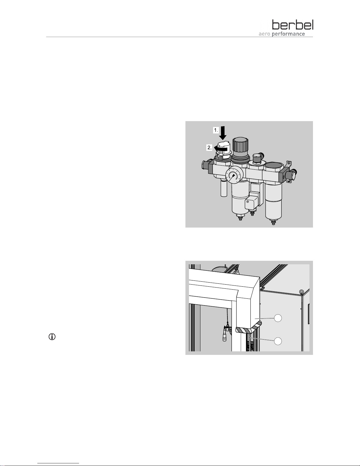
numbers (1., 2., ...):
If reference is made to elements in a legend or in
the body text, these are provided with an item
number (2):
2
1
Page 3

3
Table of contents
Safety ..............................................................................................................................................................5
Proper use ..........................................................................................................................................................5
Ban on independent conversions and modifications ..........................................................................................5
Basic safety instructions .....................................................................................................................................5
Structural features of the information on dangers ..............................................................................................7
Structural features of notices regarding material or environmental damage......................................................7
Description.......................................................................................................................................................8
Possible operating modes ..................................................................................................................................8
Basic information on the device..........................................................................................................................9
View of the device from above .........................................................................................................................10
View of the device from below with flap closed ................................................................................................11
View of the device from below with flap open ..................................................................................................12
Air extraction mode........................................................................................................................................13
Outgoing air in the separate outgoing air duct .................................................................................................14
Optimising the outgoing air line ........................................................................................................................14
Preparing for installation ................................................................................................................................18
Personnel qualifications....................................................................................................................................18
Required aids....................................................................................................................................................18
Unpacking.........................................................................................................................................................19
Checking the scope of delivery.........................................................................................................................19
Removing parts for installation .........................................................................................................................21
Removing the lower tray (lower grease tray)....................................................................................................21
Removing the "Capillar Trap" ...........................................................................................................................22
Removing the brackets.....................................................................................................................................22
Creating the installation cut-out ........................................................................................................................22
Installing the device .......................................................................................................................................24
Maintaining safety distances ............................................................................................................................24
Installing the brackets.......................................................................................................................................25
Attaching the device .........................................................................................................................................25
Aligning the device horizontally ........................................................................................................................26
Securing the locking mechanism......................................................................................................................26
Adjusting the stop for the depth setting ............................................................................................................26
Connecting the connection contact for wall box and window switch (multi-function contact) ..........................27
Creating the outgoing air connection................................................................................................................30
Installing the removed parts .............................................................................................................................32
Connecting the current supply..........................................................................................................................33
Cleaning surfaces..........................................................................................................................................35
Page 4

4
Dismantling the device...................................................................................................................................36
Disposal.........................................................................................................................................................37
Disposing of packaging.....................................................................................................................................37
deviceDisposal..................................................................................................................................................37
Technical data ...............................................................................................................................................38
Model plate .......................................................................................................................................................38
Built-in hood BEH 60 FL ...................................................................................................................................38
Built-in hood BEH 90 FL ...................................................................................................................................38
Contacting the manufacturer..........................................................................................................................39
Page 5

Safety
5
Safety
Read through this chapter carefully before installing,
using or cleaning the device.
¾ Observe all information on dangers during all
activities on the device.
¾ Enclose these instructions if you pass the device
on.
Proper use
The device can be used to extract cooking vapours
during cooking.
The device is exclusively intended for this purpose
and must only be put to this use. The device must
only be used in the manner described in these
instructions.
Any other use or modification of the device is
regarded as improper and may lead to damage.
The manufacturer accepts no liability for damage
caused as a result of improper use, incorrect
installation or incorrect operation. The device is not
intended for commercial use. Use the device in
private kitchens only.
Ban on independent conversions and
modifications
• Do not undertake any independent conversions or
modifications on the device. Conversions or
modifications without the approval of berbel
Ablufttechnik GmbH are impermissible.
• Never bridge or bypass the protective facilities
available on the device.
Basic safety instructions
This section contains basic safety instructions for
handling the device. Additional safety instructions
which affect certain actions and procedures can be
found in the relevant chapters.
• Heed all of the safety instructions and information
on dangers in these instructions.
• Check the device and all parts for visible damage.
In the event of damage, contact your specialist
dealer or the berbel customer service. The device
must only be used in flawless condition.
• Always have repair and maintenance work carried
out by qualified, specialist personnel. Otherwise,
you endanger yourself and others.
• Install the device with the enclosed brackets
exclusively on load-bearing parts of buildings
(solid construction).
• In the case of other mountings, use
correspondingly suitable mounting techniques. If
in doubt, ask your specialist dealer. Otherwise,
you endanger yourself and others.
• Use the device in private kitchens only.
Page 6

Safety
6
Avoiding dangers due to electric shock
• Have work on the voltage supply carried out by a
qualified, trained specialist electrician only.
At the very least, the specialist electrician must
have the following knowledge and skills:
− Basics of electrical engineering
− Knowledge of the country-specific regulations
and standards (in Germany e.g.
DIN 57100/VDE 0100, Part 701)
− Knowledge of the relevant safety regulations
− Knowledge of the relevant legal regulations for
gas installations (in Germany e.g. the technical
regulations for gas installations TRGI).
• Only use the device if it is connected and fused
according to the technical data.
• Do not kink or crush the mains cable.
• Do not operate the device with a damaged
electrical connection cable.
• Disconnect the device from the current supply in
the event of malfunctions.
• The mains plug must be freely accessible so that
the device can be easily and quickly disconnected
from the mains power supply in an emergency. If
the mains plug is inaccessible following
installation, an all-pole isolating device with a
contact opening of at least 3 mm must be
provided in the installation.
• If the device is brought into a warm environment
from a cold environment, moisture may form
inside the device. In this case, wait for
approximately two to three hours before starting
up the device.
• Avoid exposing the device to dripping or splashing
water. Never place objects filled with fluids, such
as e.g. vases, on the device.
• Keep the device dry.
• If fluid nevertheless enters the device:
− Immediately shut off the current supply by
removing the fuse.
− Make sure that the device's current supply
cannot be unintentionally reactivated. E.g.
designate a person to prevent the fuse from
being switched on.
− Allow the device to dry.
− Have the device checked and repaired by
trained, specialist personnel before using the
device again.
Avoiding risk of explosion
• Do not operate the device in an explosive
environment.
Avoiding fire hazard
• Make sure that the cooker top has cooled down
before covering it.
A soiled device may cause fire hazards.
• Keep the device in flawless condition and check it
regularly.
• Regularly remove any grease residues which are
present. Grease residues pose a fire hazard.
• Do not flambé beneath the device. Naked flames
may e.g. damage neighbouring cupboards.
• Only have repair work on the device carried out
by personnel trained for this purpose.
In recirculated air mode:
• A covered or sealed ventilation outlet may cause
fire hazards. Do not place any objects such as
e.g. cloths or plates on or in front of the device's
ventilation slits. In the case of recirculated air
devices, outflowing air must be able to escape
back into the kitchen through the ventilation slits
without impediments.
• No objects which may impede the air flow may be
installed above the device. Make sure that the
outflowing air is able to flow into the kitchen
without impediments.
Page 7
Safety
7
The device may only be installed above a fireplace
for solid fuels (e.g. coal-fired stove) if:
• the fireplace has a sealed cover which cannot be
removed. Otherwise, e.g. there is an increased
fire hazard due to flying sparks.
• the legal and country-specific regulations are
adhered to.
Avoiding risks of injury
• In order to prevent the risk of falling, use a stable
stepladder for all work on the device, such as e.g.
replacing the filter, installing and cleaning the
device.
• In order to prevent risks of injury due to falling
parts, use suitable mounting material.
• In order to prevent cuts due to broken glass, use
suitable protective gloves.
Avoiding the risk of suffocation
If the device and an open fireplace which is
dependent on the room air are operated
simultaneously, gases or waste gases may be
drawn into the room.
• Make sure that all of the permits required for
operation in your country are available (e.g. those
of the master chimney sweep).
• Make sure that all standards and guidelines for
operating the device in your country are observed.
• Ensure an adequate fresh air supply in the
dwelling.
• Do not allow children to play with film or other
parts of the packaging.
• Store film or other parts of the packaging in a
location which is inaccessible to children.
Preventing the risk of collapse
• The necessary wall passage must be created by a
specialist company. Wall passages influence the
building's statics. Improperly created wall
passages may lead to the collapse of the building.
Avoiding environmental damage
• Dispose of the device and its accessories
according to the legal regulations.
Structural features of the information on
dangers
The following categories of information on dangers
are contained in these instructions:
DANGER
Notices containing the word DANGER
warn of a hazardous situation which
leads to death or severe injuries.
WARNING
Notices containing the word
WARNING warn of a hazardous
situation which may lead to death or
severe injuries.
CAUTION
Notices containing the word CAUTION
warn of a situation which may lead to
slight or moderate injuries.
Structural features of notices regarding
material or environmental damage
ATTENTION
These notices warn of a situation
which leads to material or
environmental damage.
Page 8
Description
8
Description
The following illustrations show functions or
dimensions. The devices which are used are
shown as symbols. The illustrations are
intended to provide assistance to the
installation engineer. The device forms which
are shown may deviate from the actual
appearance of your devices.
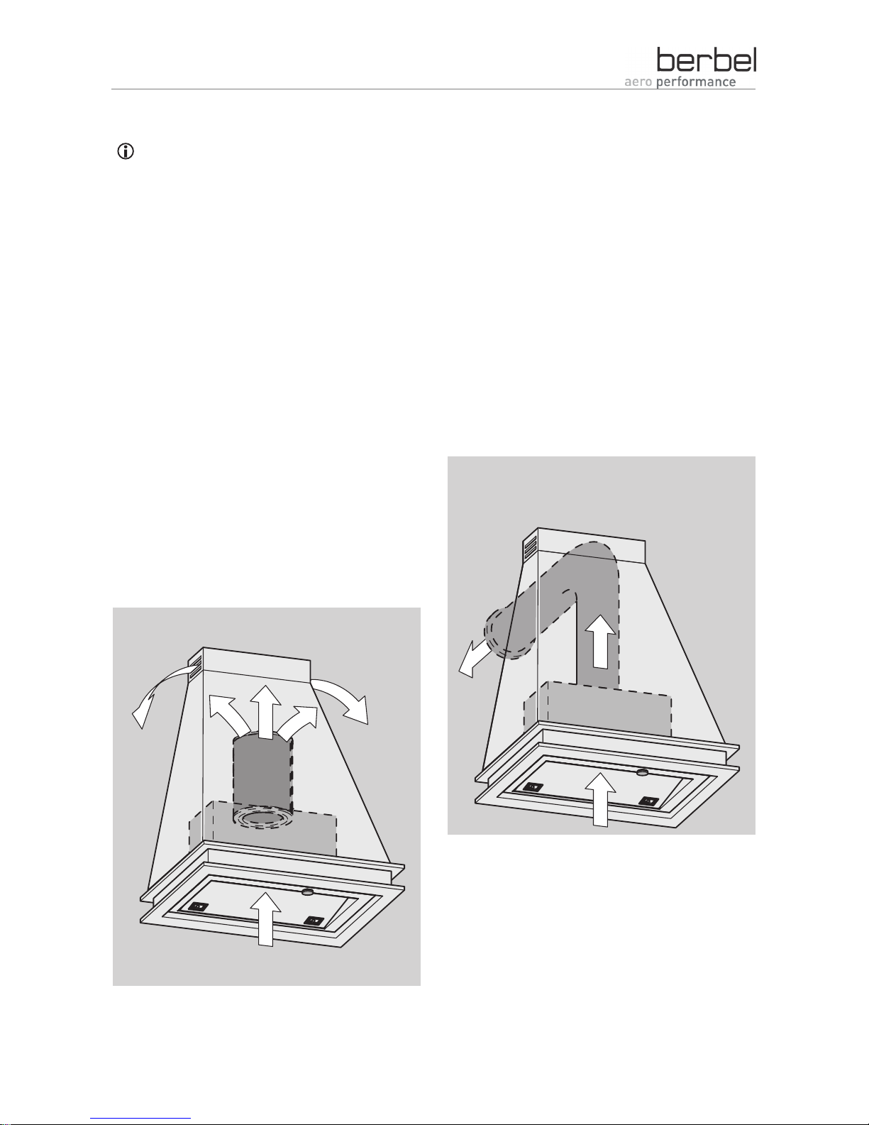
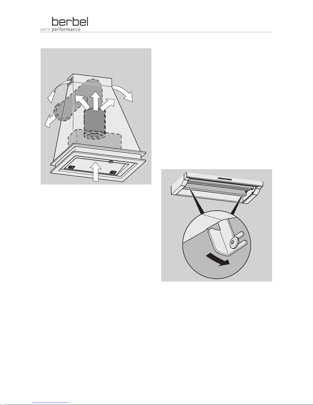
The device can be used in various operating
modes:
• Recirculated air mode
• Air extraction mode
• Hybrid mode
Installation of the device differs depending on the
operating mode which is desired. The different
installation of the individual operating modes is
described in the following sections.
Possible operating modes
Installation for recirculated air mode
The device intakes room air, filters the room air and
returns the odour-free, cleaned room air into the
room.
During installation, a recirculating air filter BUF is
placed onto the device's fan outlet.
¾ Make sure that the cross-section of the ventilation
slits in the upper elements is greater than
200 cm
2
.
¾ Make sure that the filter filling can be replaced at
a later point in time.
The filter filling must be replaced at regular
intervals.
Installation for air extraction mode
The device intakes room air, filters the room air and
conducts the room air outside.
Page 9
Description
9
Installation for hybrid mode
The device intakes room air, filters the room air, and
conducts part of the room air outside and returns
part of the room air, cleaned and odour-free, into
the room.
During installation, a hybrid filter BHF is placed onto
the device's fan outlet. The outgoing air line is
connected to the hybrid filter.
¾ Make sure that the cross-section of the ventilation
slits in the upper elements is greater than
200 cm
2
.
¾ Make sure that the filter filling can be replaced at
a later point in time.
The filter filling must be replaced at regular
intervals.
Basic information on the device
The device is designed for installation in cupboards.
The front panel can be pulled out to obtain a larger
intake area. The rear end position of the front panel
can be adjusted.
The device's functions are controlled using the
control in the centre of the front panel.
The two brackets which are contained in the scope
of delivery are screwed laterally to the inner walls of
the cupboard.
Once the levers in the device have been pretensioned, the device is hooked in from below. The
tensioned levers engage automatically when the
end position has been reached.
Page 10
Description
10
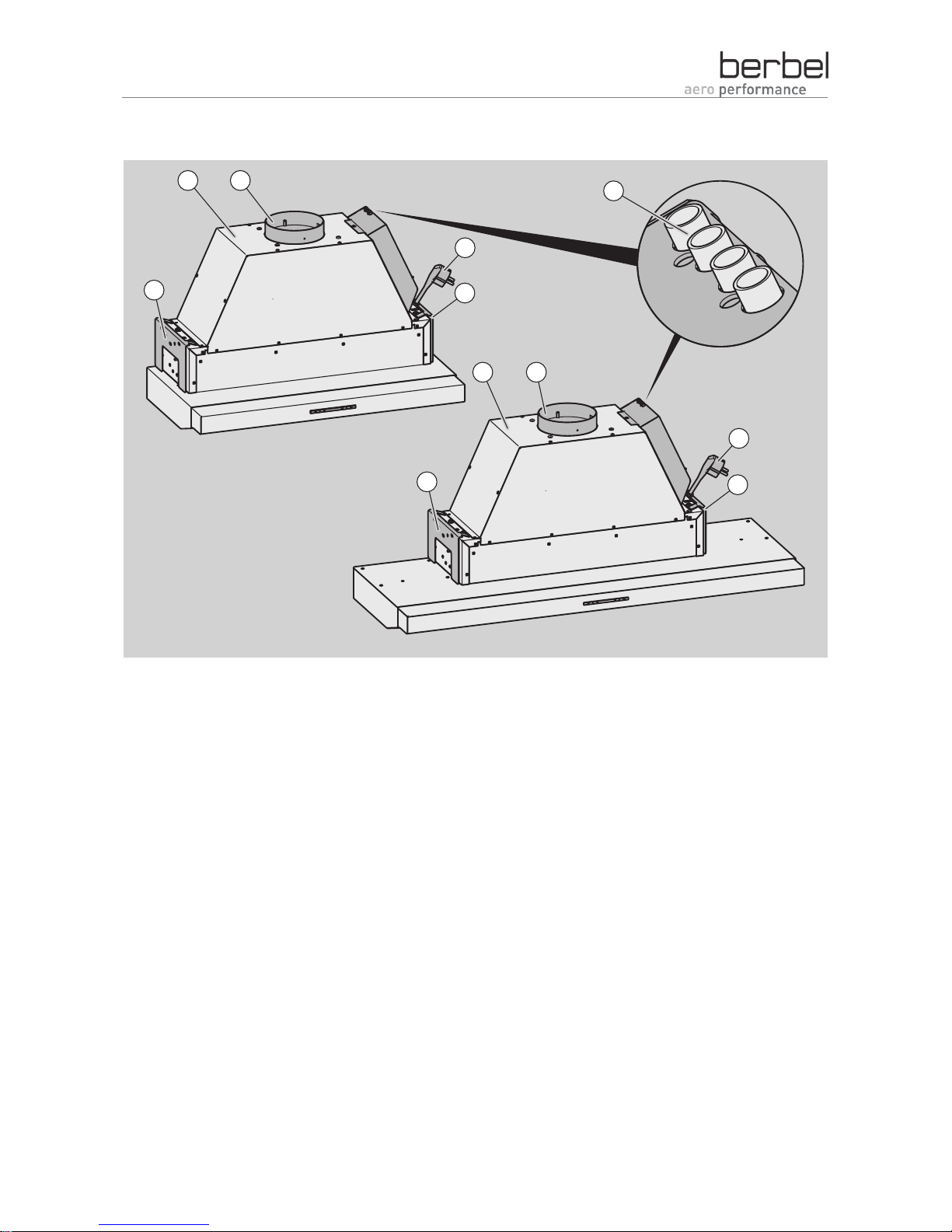
View of the device from above
31
2
4
5
6
7
3
6
7
4
Built-in hood BEH 60 FL Contacts for window switches (multi-function
contact) and wall box BMK
Built-in hood BEH 90 FL Right bracket
Fan outlet with guide aid for filter and outgoing
air line
Left bracket
Mains plug
Page 11
Description
11
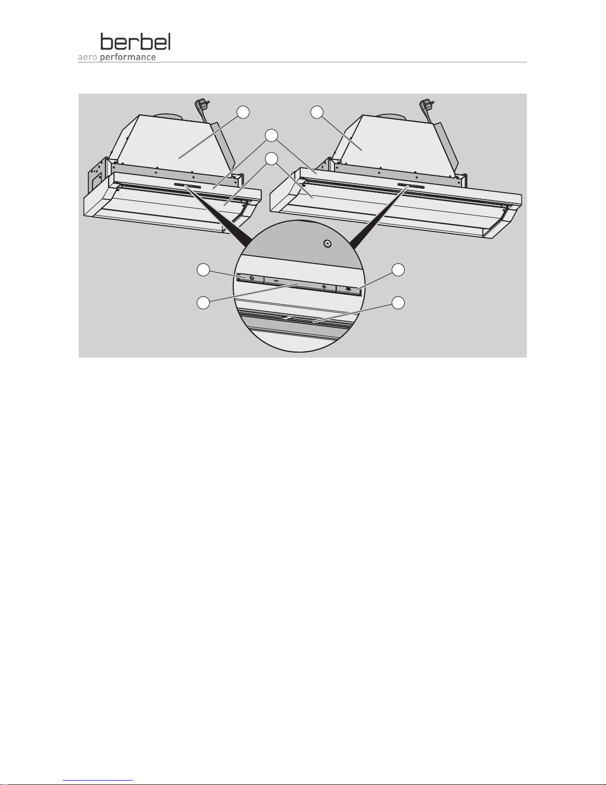
View of the device from below with flap closed
7
8
4
6
5
1
3
2
Built-in hood BEH 60 FL Lighting ON/OFF button
Built-in hood BEH 90 FL Lighting
Extension Change output level button
Flap with lower grease tray Switch on run-on button
Page 12
Description
12
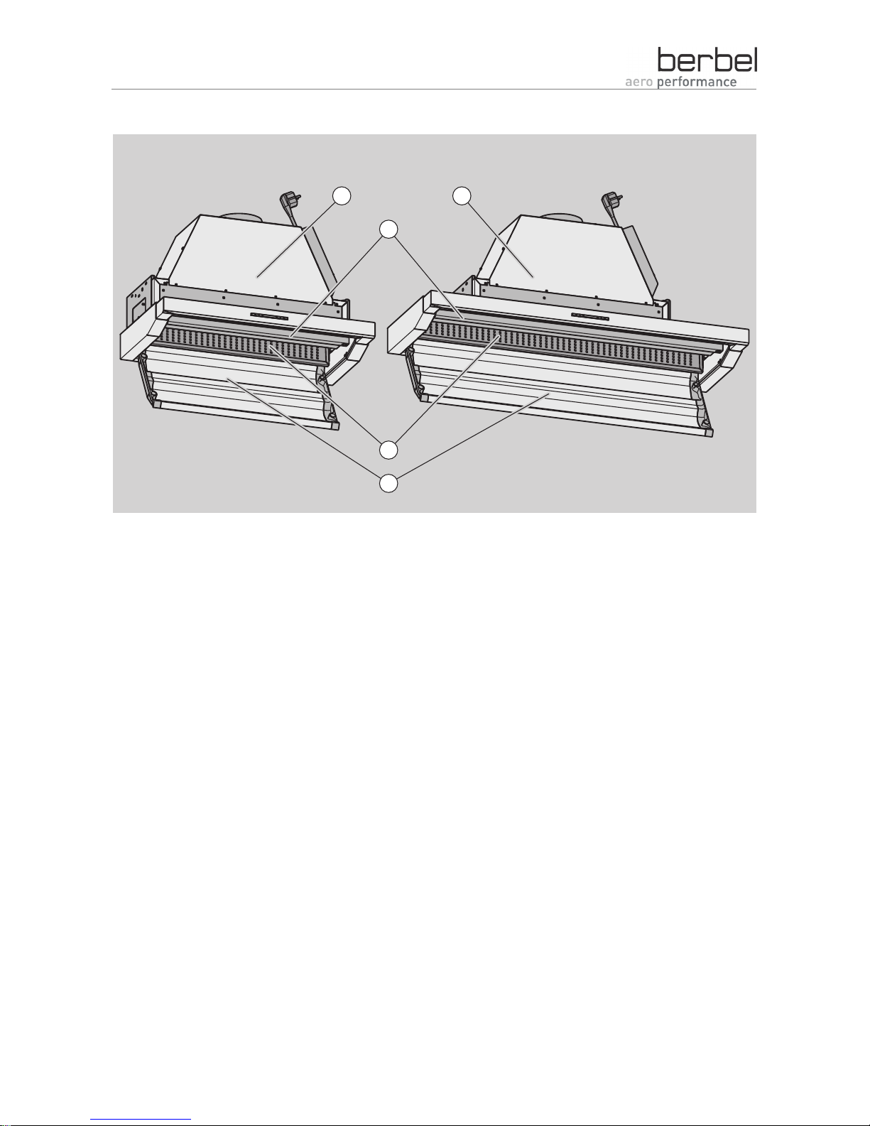
View of the device from below with flap open
3
4
5
1 2
Built-in hood BEH 60 FL "Capillar Trap"
Built-in hood BEH 90 FL Flap with lower grease tray
Upper grease tray
Page 13

Air extraction mode
13
Air extraction mode
DANGER
Danger of suffocation due to a lack of
oxygen on simultaneous operation of
the device and an open fireplace.
¾ On simultaneous operation with
devices which are dependent on the
room air, such as e.g. a gas cooker,
chimney or gas heater, make sure
that no gases or exhaust gases are
drawn into the room.
¾ Ensure an adequate fresh air supply
in the dwelling.
¾ Make sure that the legally prescribed
requirements of your Federal state's
regulations pertaining to fireplaces
(FeuV)) are adhered to.
¾ Make sure that the permit required
from the master chimney sweep to
operate the extractor hood is
available.
Measures for an adequate fresh air supply:
• Operate the device only with a window contact
switch connected.
• Open the windows.
• Open the doors.
• Install a berbel wall box BMK.
• Make sure that the open fireplace's prescribed
forced ventilation functions.
WARNING
Danger of suffocation due to a lack of
oxygen on operation of the device.
¾ Ensure an adequate fresh air supply
in the dwelling.
¾ Make sure that the device is
connected to a window contact
switch to ensure hazard-free
operation.
¾ Make sure that the country-specific,
legally prescribed regulations (in
Germany e.g. the requirements of
your Federal state's regulations
pertaining to fireplaces (FeuV)) are
adhered to.
If an extractor hood and a fireplace which is
dependent on the room air (e.g. gas-, oil- or coalfired heaters, chimneys, hot water boilers, gas hobs
or gas ovens) are operated at the same time, the
following prerequisites must be met:
¾ Your master chimney sweep has approved the
installation of the extractor hood beforehand.
¾ Installation must be carried out under adherence
to the country-specific regulations (e.g. the
regulations pertaining to fireplaces (FeuV)).
¾ Installation must be carried out under adherence
to the official and legal regulations (e.g. state
building ordinances).
In air extraction mode, the device intakes room air
and conducts it outside via the outgoing air line.
The device is only able to conduct the volume of air
away which flows into the kitchen as supply air.
The cross-section, length, type and routing of the
outgoing air line extensively influence the extraction
efficiency of an extractor hood.
Power losses and noises arise e.g. due to air which
is diverted abruptly in the outgoing air line.
Page 14

Air extraction mode
14
The device's optimal output is obtained if, when
installing the outgoing air line, you ensure that:
• the outgoing air line is as short and direct as
possible
• the transported room air is able to flow through
the outgoing air line without vortices and back
pressure
• the prescribed outgoing air line cross-section is
adhered to
• the recommended characteristics of the outgoing
air line are adhered to throughout.
The following section explains which requirements
and characteristics the outgoing air line has to
meet.
Outgoing air in the separate outgoing
air duct
DANGER
Danger of suffocation due to smoke or
exhaust gases.
¾ Make sure that the outgoing air duct
which is used is exclusively intended
for operating an extractor hood.
¾ Make sure that the outgoing air duct
is only used by this device. On
connection of the device to an active
outgoing air duct, such as e.g. a
ventilation shaft or chimney, gases
or exhaust gases may be drawn into
the room.
DANGER
Fire hazard due to combustible
outgoing air line.
If combustible outgoing air lines are
routed through a second room or attic,
fire may spread to other rooms.
¾ Make sure that the outgoing air line
consists of non-combustible material
in accordance with
DIN 4102 Class A1.
The extracted room air must only be conducted
outside via a separate outgoing air duct intended for
this purpose.
¾ Make sure that the outgoing air duct which is used
is only used as an outgoing air line by the device.
Optimising the outgoing air line
Conducting the room air away directly
Conduct the extracted room air outside directly and
over the shortest route. Long routes generate
additional, undesired air resistance.
¾ Make sure that the outgoing air line which leads
outside is as direct and short as possible.
Using pipes with low air resistance
Exclusively use pipes with a smooth inner surface.
These pipes offer low air resistance.
Avoid the installation of:
• Spiral hoses
• Flexible pipes
• Flat diverters.
These types of pipe have high air resistance and
reduce the extractor hood's output.
Page 15

Air extraction mode
15
¾ Make sure that the outgoing air line has a smooth
inner surface.
Exclusively use bends with optimised air ducting
and a smooth inner surface. These bends offer low
air resistance.
Avoid the installation of bends with sharp-edged air
ducting.
These bends have high air resistance and generate
noises. These bends reduce the extractor hood's
output.
¾ Make sure that bends in the outgoing air line have
a smooth inner surface and that air ducting is
optimised.
Using the most favourable cross-section
The minimum outgoing air line cross-section is
125 mm in the case of 125 mm systems (BEH
60/90 N) and 150 mm in the case of 150 mm
systems (all other berbel extractor hoods).
Each reduction of the outgoing air line generates
undesired air resistance, reduces output and
causes noises.
Avoid:
• Outgoing air lines with small diameters
• Sharp-edged flat outgoing air ducts
• Conventional wall boxes
These have high air resistance and generate
noises. They reduce the extractor hood's output.
¾ Make sure that the outgoing air line's minimum
cross-section is not less than the cross-section of
the fan outlet.
Outgoing air line through the old chimney
DANGER
Danger of suffocation due to smoke or
exhaust gases.
¾ A master chimney sweep must
approve the chimney as an outgoing
air line prior to the installation of the
extractor hood.
DANGER
Fire hazard due to combustible
outgoing air line.
If combustible outgoing air lines are
routed through a second room or attic,
fire may spread to other rooms.
¾ Make sure that the outgoing air line
consists of non-combustible material
in accordance with
DIN 4102 Class A1.
If you use a chimney as an outgoing air line,
increased air resistance must be anticipated
depending on the length of the chimney.
The extracted air must be introduced into the
chimney using a bend which is bent upwards at an
angle of 90°. This avoids any possible back
pressure.
Page 16

Air extraction mode
16
¾ Make sure that the connection in the chimney is
carried out using a bend which is bent upwards at
an angle of 90°.
Outgoing air line through the roof
DANGER
Fire hazard due to combustible
outgoing air line.
If combustible outgoing air lines are
routed through a second room or attic,
fire may spread to other rooms.
¾ Make sure that the outgoing air line
consists of non-combustible material
in accordance with
DIN 4102 Class A1.
ATTENTION
Water damage to the device due to the
absence of a moisture condensate
collector.
¾ Install a moisture condensate
collector in the outgoing air line.
If the outgoing air line is routed through the roof,
you must ensure that:
• the cross-section of the roof passage is no less
than that of the fan outlet
• the roof passage does not reduce the cross-
section of the outgoing air line
• a moisture condensate collector is integrated into
the outgoing air line.
Outgoing air line through an exterior wall
DANGER
Fire hazard due to combustible
outgoing air line.
If combustible outgoing air lines are
routed through a second room or attic,
fire may spread to other rooms.
¾ Make sure that the outgoing air line
consists of non-combustible material
in accordance with
DIN 4102 Class A1.
If the outgoing air line is routed through the exterior
wall, you must ensure that:
• the cross-section of the outgoing air line is no less
than that of the fan outlet
• the wall passage does not reduce the cross-
section of the outgoing air line.
The wall box must meet the following requirements:
• The cross-section of the fan outlet must not be
reduced in the wall box.
• The louvered cover of the wall box must ventilate
over a wide area.
Page 17

Air extraction mode
17
Make sure that
• the slats of the louvered cover of the wall box are
not narrow and thick
• the slats of the louvered cover of the wall box are
not positioned sharply downwards.
• no insect screen is installed in the wall box. Insect
screens impair the cross-section of the outgoing
air line completely.
¾ Use only flow-optimised wall boxes (e.g. BMK-
F/L).
Page 18

Preparing for installation
18
Preparing for installation
This chapter explains which prerequisites have to
be met for installation. Carry out all of the steps
contained in these instructions in succession.
WARNING
Risk of injury due to falling parts in the
event of improper mounting.
¾ Ensure the carrying capacity of the
cupboard.
¾ Use suitable mounting material only.
The enclosed mounting material is
exclusively suitable for mounting in a
stable cupboard (e.g. 16 mm
wooden plate). In the case of other
installation conditions, contact berbel
Ablufttechnik GmbH and ask about
alternative mounting options prior to
installation.
¾ Make sure that the device is
mounted correctly.
¾ Make sure that the mains voltage corresponds to
the voltage specified on the model plate.
¾ Make sure that connection to the voltage supply is
only carried out following installation.
Personnel qualifications
Two persons are required to mechanically install the
device.
These installation engineers must have adequate
specialist trade knowledge.
Necessary specialist trade knowledge includes:
• Knowledge of the industrial safety regulations
• Knowledge of reading technical drawings
• Experience of using electrical and mechanical
tools
• Knowledge of mounting technology
• Basic knowledge of ventilation technology
• Ideally, several years' experience of installing
extractor hoods and other additional
qualifications, such as e.g. joinery training, are
also available.
Persons without this specialist knowledge must be
familiarised with installation by an experienced
installation engineer.
Required aids
The following tools, materials and underlays are
required for installation:
1 2
4
3
5
Phillips screwdriver
2.5 mm Allen ball key
Thick cardboard to protect e.g. the cooker top
and the work surface
Installation instructions
Jigsaw
Page 19

Preparing for installation
19
Unpacking
CAUTION
Risk of cuts due to broken glass.
¾ Wear protective gloves.
¾ Unpack the device carefully.
¾ Do not reach into broken glass.
ATTENTION
Damage to surfaces due to improper
unpacking.
¾ Cut through the packing tape and
retaining straps with a pair of
scissors.
¾ Do not cut into the protective
cardboard box.
ATTENTION
Scratched surfaces possible due to
sharp-edged metal objects, e.g. belt
buckles or tools during transportation.
¾ Transport the device without coming
into contact with objects which may
scratch the device.
¾ Remove the packaging film and the cardboard
box.
¾ If available, cut through the retaining strap with a
pair of scissors.
¾ Cut through the packing tape with a pair of
scissors.
¾ Remove the loosely enclosed parts from the
packaging.
CAUTION
Risk of injury due to the heavy
extractor hood falling down.
¾ Only lift the device with two persons.
¾ Protect the surfaces of the working area e.g. with
thick cardboard.
¾ Remove the device from the packaging.
¾ Lay the device, with the front side facing up, on a
flat, protective surface.
Checking the scope of delivery
¾ Check that the supplied parts are complete, as
described in the following section.
¾ Check the supplied parts for damage.
¾ If parts are damaged or missing, contact your
specialist berbel dealer or the customer service.
Page 20

Preparing for installation
20
Scope of delivery, BEH 60 FL
6 ×
1
2 43
5
Built-in hood BEH 60 FL
Left bracket
Right bracket
6 screws (Phillips) 4.5 x 16 mm
Installation instructions
Scope of delivery, BEH 90 FL
8 ×
1
2 43
5
Built-in hood BEH 90 FL
Left bracket
Right bracket
8 screws (Phillips) 4.5 x 16 mm
Installation instructions
Page 21

Preparing for installation
21
Optional accessories
Optional accessories:
1 2
3
For hybrid mode only:
Hybrid filter BHF 125
For recirculated air mode only:
Recirculating air filter BUF 125
Wall box BMK-F/L
Removing parts for installation
Prior to installation, certain installed parts have to
be removed or dismantled to ensure that installation
of the device is as safe and hazard-free as possible.
¾ Carry out all of the following steps in succession.
¾ Lay the device, with the rear side facing down, on
a flat, clean and protective surface.
The following illustrations show the installed
device. They are merely intended to provide
assistance to the installation engineer. During
these steps, the device must lie on its rear wall,
and the actions must be implemented according
to the perspective.
Removing the lower tray (lower grease
tray)
¾ Open the flap by pulling it downwards at the
rounded edge.
¾ Grip the grease tray, which is folded down
vertically, at the sides using both hands.
¾ Raise the lower grease tray approx. 2 cm (1.).
¾ Release the lower grease tray by pulling it
forwards (2.).
1.
2.
Page 22

Preparing for installation
22
¾ Remove the lower grease tray.
Removing the "Capillar Trap"
¾ Grip the "Capillar Trap" at the sides.
¾ Pull the "Capillar Trap" off downwards.
Removing the brackets
Proceed as follows to remove the brackets from the
device:
¾ Press both levers at the side in the "Capillar Trap"
shaft backwards (1.) until they audibly engage.
¾ Pull the two brackets off (2.).
¾ Mark the brackets "Left" and "Right".
2.
1.
Creating the installation cut-out
The installation cut-out must have the following
dimensions:
560
190
Page 23

Preparing for installation
23
A saw (e.g. jigsaw) is required for this step.
¾ Protect all surfaces within your working area from
damage, e.g. with thick cardboard or foamed
material.
¾ Saw out the installation cut-out according to the
dimensions specified for your device.
Page 24

Installing the device
24
Installing the device
WARNING
Risk of injury due to falling parts.
¾ Make sure that nobody is standing
beneath the working area during
work.
WARNING
Risk of injury due to falling parts in the
event of improper mounting.
¾ Ensure the carrying capacity of the
cupboard.
¾ Use suitable mounting material only.
The enclosed mounting material is
exclusively suitable for mounting in a
stable cupboard (e.g. 16 mm
wooden plate). In the case of other
installation conditions, contact berbel
Ablufttechnik GmbH and ask about
alternative mounting options prior to
installation.
¾ Make sure that the device is
mounted correctly.
ATTENTION
Damage due to falling parts.
¾ Protect surfaces and devices
(e.g. cooled cooker top) beneath
your working area from damage,
e.g. with thick cardboard.
The device is suspended with two brackets.
Maintaining safety distances
The following illustrations show functions or
dimensions. The devices which are used are
shown as symbols. The illustrations are
intended to provide assistance to the
installation engineer. The device forms which
are shown may deviate from the actual
appearance of your devices.
The following legally prescribed minimum distances
must be adhered to:
Designation Dimension
Y 0 mm
X With gas cooker tops:
At least 650 mm
With electric cooker tops:
At least 350 mm
Recommended distance:
550 mm
Page 25

Installing the device
25
Installing the brackets
A large Phillips screwdriver is required for this step.
The two brackets which are contained in the scope
of delivery are screwed laterally to the inner walls of
the cupboard.
The bent metal lugs are at the top and point to the
inner side of the cupboard.
¾ Insert the bracket marked right on the right inner
wall of the cupboard (1.).
¾ Make sure that the rear edge of the bracket lies
flush against the rear wall of the cupboard.
¾ Make sure that the lower edge of the bracket is
flush with the lower edge of the bottom of the
cupboard.
¾ Secure the bracket using the Phillips screws
enclosed in the scope of delivery.
¾ Tighten the Phillips screws (2.).
¾ Make sure that the bracket is firmly mounted in
the correct installation position.
1.
2.
¾ Repeat the procedure with the left bracket.
Attaching the device
DANGER
Danger due to falling parts in the event
of improper mounting.
¾ The enclosed mounting material is
exclusively suitable for mounting in
the installation cut-out of a loadbearing and stable body (e.g.
cupboard body).
¾ Make sure that the carrying capacity
is sufficient and use suitable
mounting material.
No tools are required for this step.
¾ Make sure that the two levers at the sides in the
rear "Capillar Trap" are engaged.
¾ Lift the device from below into the base plate with
the installation cut-out using two persons.
Page 26

Installing the device
26
The levers automatically engage in the end position
and hold the device.
¾ Push the device upwards until both levers
engage.
¾ Make sure that both levers have engaged.
Aligning the device horizontally
No tools are required for this step.
The device's horizontal alignment can be adjusted
slightly. Proceed as follows to do this:
¾ Push the device to the desired position by
pressing against the side of the device with your
hand.
Securing the locking mechanism
A 2.5 mm Allen ball key is required for this step.
Proceed as follows to secure the levers after
installing the device:
¾ Re-tension the levers with your thumb.
¾ Tighten the two levers using the relevant screw.
Adjusting the stop for the depth setting
A 2.5 mm Allen ball key is required for this step.
The position of the front panel can be adjusted
whilst inserted. The stop for the depth setting is
adjusted as follows:
¾ Loosen the two screws.
Page 27

Installing the device
27
¾ Push the front panel to the desired position.
¾ Make sure that the front panel is in the correct
position.
¾ Push the stops forwards up to the front panel.
¾ Tighten the screws.
Connecting the connection contact for
wall box and window switch (multifunction contact)
DANGER
Fatal electric shock due to improper
connection.
¾ Only have work on the voltage
supply carried out by a qualified,
trained specialist electrician under
consideration of the country-specific
regulations and standards (in
Germany e.g.
DIN 57100/VDE 0100, Part 701).
¾ Have the following steps carried out by a
specialist electrician only.
A window switch and a berbel wall box (e.g. BMK-F)
can be connected to the device. The cable
terminals for this are mounted on the device's fan
housing.
Connection schematic for the multi-function contact
and the wall box contact
ATTENTION
Damage to the electronics if the
polarity of the control cable is incorrect.
¾ Make sure that the polarity of the
control cable is correct.
¾ Only connect wire 1 to terminal 1
and wire 2 to terminal 2.
7
4
1
5
6
2
3
Terminal for the multi-function contact (F-K)
Terminal for the wall box (BMK)
Control cable
Power supply unit
Wall box BMK-F
Actuation contact, potential-free
Control box for the berbel extractor hood
Connection terminal for the wall box
The connection terminal for the wall box
automatically controls the remotely controlled wall
box BMK.
Page 28

Installing the device
28
The control cable must be routed from the wall box
to the connection terminals for the wall box in the
extractor hood.
The connection terminals for the wall box are
marked "BMK" and "Wall box" in the extractor hood.
In order to connect the control cable, the control
cable's two wires must be connected to terminals 1
and 2 for the wall box in the extractor hood. The
wires are numbered. The actuation contact is
potential-free.
• The wall box is closed when the actuation contact
in the extractor hood is open (see connection
schematic).
• The wall box is open when the actuation contact
in the extractor hood is closed.
Connection of the BMK-F series wall box is
described in the following section.
For this step, a small standard screwdriver is
required for the connection terminals in the berbel
extractor hood.
¾ Route the wall box control cable to the extractor
hood.
¾ Make sure that the terminals for the wall box
contact in the extractor hood are accessible.
The connection terminals for the multi-function
contact and the wall box contact are located in the
upper corner of the control box. The connection
terminals are marked "Window switch" and "BMK"
or "Wall box". The terminal pairs are labelled "1"
and "2".
Proceed as follows to connect the control cable:
¾ Unscrew the screw for "BMK" terminal 1.
¾ Take up offset wire 1 of the control cable.
¾ Guide wire 1 into terminal 1.
¾ Make sure that the control cable's wire connector
sleeve is completely in the terminal.
¾ Make sure that the control cable's insulation is not
in the terminal.
Page 29

Installing the device
29
¾ Tighten the screw for terminal 1.
¾ Connect wire 2 to "BMK" terminal 2 in the same
manner.
The control cable for the wall box is connected.
Connection terminal for the multi-function
connection
A window switch can be connected to the multifunction connection. The extractor hood fan is then
only operational when the window is open.
The control cable must be routed from the window
switch to the connection terminals for the multifunction connection in the extractor hood.
The connection terminals for the multi-function
connection are marked "Window switch" in the
extractor hood.
In order to connect the control cable, the control
cable's two wires must be connected to terminals 1
and 2 for the multi-function connection in the
extractor hood.
Connection of the multi-function connection is
described in the following section.
For this step, a small standard screwdriver is
required for the connection terminals in the berbel
extractor hood.
¾ Route the window switch control cable to the
extractor hood.
¾ Make sure that the terminals for the multi-function
connection in the extractor hood are accessible.
¾ Pull the control cable through the cable passage
hole to the extractor hood's control box.
The connection terminals for the multi-function
contact and the wall box contact are located in the
upper corner of the control box. The connection
terminals are marked "Window switch" and "BMK"
or "Wall box". The terminal pairs are labelled "1"
and "2".
Proceed as follows to connect the control cable:
¾ Unscrew the screw for "Window switch"
terminal 1.
Page 30

Installing the device
30
¾ Take up offset wire 1 of the control cable.
¾ Guide wire 1 into terminal 1.
¾ Make sure that the control cable's wire connector
sleeve is completely in the terminal.
¾ Make sure that the control cable's insulation is not
in the terminal.
¾ Tighten the screw for terminal 1.
¾ Connect wire 2 to "Window switch" terminal 2 in
the same manner.
The control cable for the wall switch is connected.
Creating the outgoing air connection
The device can be installed for various operating
modes:
• Recirculated air mode
• Air extraction mode
• Hybrid mode
Installation for the individual operating modes is
described in the following sections.
Installing the device for recirculated air mode
WARNING
Risk of falling when replacing filter.
¾ Use a stable stepladder.
CAUTION
Risk of injury due to falling parts.
¾ Make sure that nobody is standing
beneath the device during work.
ATTENTION
Damage due to falling parts.
¾ Protect surfaces and devices
(e.g. cooled cooker top) beneath
your working area from damage,
e.g. with thick cardboard.
To ensure that the filter is installed correctly, the
device's filter seat is equipped with an approx.
two cm-high guide aid.
The filter is inserted correctly when the lower edge
of the filter lies fully on the fan housing.
Page 31

Installing the device
31
¾ Position the recirculating air filter on the device
from above using the folding handle.
¾ Make sure that the filter is positioned correctly.
Installing the device for air extraction mode
WARNING
Risk of falling during work carried out
in elevated positions.
¾ Use a stable stepladder.
CAUTION
Risk of injury due to falling parts.
¾ Make sure that nobody is standing
beneath the device during work.
ATTENTION
Damage due to falling parts.
¾ Protect surfaces and devices
(e.g. cooled cooker top) beneath
your working area from damage,
e.g. with thick cardboard.
¾ Push the outgoing air line firmly onto the fan's
guide aid.
¾ Mask the transition between the outgoing air line
and the guide aid with sealing tape.
¾ Make sure that the outgoing air line is correctly
connected.
Installing the device for hybrid mode
WARNING
Risk of falling when replacing filter.
¾ Use a stable stepladder.
Page 32

Installing the device
32
CAUTION
Risk of injury due to falling parts.
¾ Make sure that nobody is standing
beneath the device during work.
ATTENTION
Damage due to falling parts.
¾ Protect surfaces and devices
(e.g. cooled cooker top) beneath
your working area from damage,
e.g. with thick cardboard.
To ensure that the filter is installed correctly, the
device's filter seat is equipped with an approx.
two cm-high guide aid.
The filter is inserted correctly when the lower edge
of the filter lies fully on the fan housing.
¾ Position the hybrid filter on the device from above.
¾ Make sure that the filter is positioned correctly.
¾ Slide the outgoing air line into the filter.
¾ Mask the transitions with sealing tape.
¾ Make sure that the outgoing air line is correctly
connected.
Installing the removed parts
Following installation, install the removed parts as
follows:
Page 33

Installing the device
33
Installing the "Capillar Trap"
¾ Insert the "Capillar Trap" into the device by
pressing it firmly upwards.
The "Capillar Trap" does not engage; instead, it is
merely clamped in.
Installing the lower grease tray
¾ Grip the grease tray using both hands.
¾ Guide the flap into the device from below until the
flap guide grooves are simultaneously positioned
in front of the device's guide pins.
¾ Press the grease tray backwards into the device
(1.).
¾ Pull the grease tray downwards (2.) until it
engages.
¾ Make sure that the grease tray is inserted
correctly. The grease tray is correctly inserted
when the flap can be moved easily.
1.
2.
Closing the lower flap
¾ Close the flap by pressing it up until both retaining
magnets audibly make contact.
Connecting the current supply
DANGER
Fatal electric shock due to improper
connection.
¾ Only have work on the voltage
supply carried out by a qualified,
trained specialist electrician under
consideration of the country-specific
regulations and standards (in
Germany e.g.
DIN 57100/VDE 0100, Part 701).
Page 34

Installing the device
34
¾ Insert the mains plug into the socket.
The berbel extractor hood is installed and ready to
operate.
Page 35

Cleaning surfaces
35
Cleaning surfaces
ATTENTION
Damage to surfaces due to sharpedged objects or aggressive cleaning
agents.
¾ Never use sharp-edged objects,
scouring agents or aggressive
cleaning agents.
¾ Use a soft, moist cloth.
¾ Clean surfaces with a soft, moist cloth and a mild
household cleaning agent.
Page 36

Dismantling the device
36
Dismantling the device
DANGER
Fatal electric shock due to improperly
carried out electrical work.
¾ Only have work on the voltage
supply carried out by a qualified
specialist electrician under
consideration of the country-specific
regulations and standards (in
Germany e.g.
DIN 57100/VDE 0100, Part 701).
WARNING
Risk of falling when replacing filter.
¾ Use a stable stepladder.
CAUTION
Risk of injury due to falling parts.
¾ Make sure that nobody is standing
beneath the device during work.
ATTENTION
Damage due to falling parts.
¾ Protect surfaces and devices
(e.g. cooled cooker top) beneath
your working area from damage,
e.g. with thick cardboard.
Two persons are required to dismantle the device.
A small standard screwdriver, a Phillips screwdriver
and a 2.5 mm Allen ball key are required for this
step.
Proceed as follows to dismantle the device:
¾ Interrupt the device's voltage supply at all poles.
¾ Pull the mains plug off.
¾ Remove any existing connection cables for the
wall box and multi-function contact.
Hybrid and air extraction mode only:
¾ Remove the outgoing air line.
Hybrid and recirculated air mode only:
¾ Remove the filter.
¾ Open the lower flap.
¾ Loosen the two screws at the levers.
ATTENTION
Damage due to falling parts.
¾ Protect surfaces and devices
(e.g. cooled cooker top) beneath
your working area from damage,
e.g. with thick cardboard.
¾ Hold the device with two persons.
¾ Push the two levers backwards until they engage.
¾ Lower the device with two persons.
¾ Loosen the bracket screws.
¾ Remove the bracket screws.
¾ Remove the brackets.
The device has been dismantled.
Page 37

Disposal
37
Disposal
Disposing of packaging
DANGER
Danger of suffocation due to parts of
the packaging (e.g. films and
polystyrene).
¾ Store film or other parts of the
packaging in a location which is
inaccessible to children.
ATTENTION
Environmental damage due to
improper disposal of the packaging.
¾ Never dispose of the packaging in
the normal domestic refuse.
¾ Have the packaging properly
recycled in an environmentallyfriendly manner.
The packaging offers protection against
transportation damage.
Only the original packaging guarantees adequate
protection during transportation.
¾ Retain the packaging during the warranty period.
The packaging materials have been selected
according to environmental compatibility aspects
and are manufactured from recyclable materials.
After use, the packaging materials can be recycled.
Valuable raw materials can therefore be saved.
• The exterior packaging consists of cardboard.
• The filler material and the inserts consist of
cardboard or polystyrene.
• The protective films and bags consist of
polyethylene (PE).
¾ Dispose of the packaging according to material
segregation and in an environmentally-friendly
manner.
deviceDisposal
ATTENTION
Environmental damage due to
improper disposal of electronic
components.
¾ Never dispose of the device in the
normal domestic refuse at the end of
its useful life.
¾ Ask your municipal or local
administration about options for
recycling or disposing of the device
in a proper and environmentallyfriendly manner.
¾ Dispose of the device according to the legal
regulations via a specialist disposal company.
Page 38

Technical data
38
Technical data
Model plate
The model plate can be found inside the device
behind the lower grease tray flap.
The model plate contains the following information:
• Manufacturer
• Manufacturer's address
• Device type
• Voltage
• Total output
• Serial number
• Year of construction
• Symbols of the legal regulations to which the
device adheres and test symbols.
Built-in hood BEH 60 FL
Width 599 mm
Depth 330 mm
Height 363 mm
Max. fan output,
free-blowing
1 fan with 600 m³/h
Weight
(air extraction
mode)
Approx. 15 kg
Weight
(recirculated air
mode)
Approx. 15 kg (without
corresponding filter)
Power
consumption
162 W
(at highest output level)
LED bulb 24 V/6 W
Built-in hood BEH 90 FL
Width 899 mm
Depth 330 mm
Height 363 mm
Max. fan output,
free-blowing
1 fan with 600 m³/h
Weight
(air extraction
mode)
Approx. 18 kg
Weight
(recirculated air
mode)
Approx. 18 kg (without
corresponding filter)
Power
consumption
163 W
(at highest output level)
LED bulb 24 V/7 W
The device has been manufactured under
adherence to the regulations of VDE 60335-2-31
and complies with the following directives and laws:
• EMC Directive (EU Directive 2004/108/EEC)
• Low-voltage Directive (2006/95/EU).
We reserve the right to implement technical
changes.
Page 39

Contacting the manufacture
r
39
Contacting the manufacturer
If you have any questions which are not answered
by these instructions, contact:
berbel Ablufttechnik GmbH
Sandkampstraße 100
D-48432 Rheine
Telephone +49 (0)800/56 06 06-0*
Fax +49 (0)800/56 06 06-1*
Internet www.berbel.de
*) Free from the German land line
Page 40

40
© KONTECXT GmbH Technische Dokumentation
D-45145 Essen
www.technische-dokumentation.de
Printed in Germany
 Loading...