

Page 1
21
54 6
87 9
30
start
stop
event 1
event 2
hold
shift
select
t
2
t
1
t
0
prog
memo
1050°C 1180°C 1250°C
150°
C 800°C 900°C
rmp3
rmp1
rmp2
tmp
2
tmp
1
°C/h
h.min
°C
°F/h
°F
Z3
Z 1
Z2
THERMOCOMPUTER
TC 505
Technical Manual
Programme Controller
TC 505 / TC507
> V1.30 (flat case)
21
54 6
87 9
30
sta rt
sto p
o
eve nt 1
eve nt 2
shi ft
sel ect
pro g
mem o
dwe ll
tim e
ski p!
hol d!
endp.h old
°C/h
h.mi n
°C
°F/h
°F
k
prog#
seg# value
rmp
tmp
Z3
Z1
Z2
T H E R M O C O M P U T E R
TC 5 0 7
Page 2
2
1. General Information
In most applications the bentrup TC500 series controller (TC505 and TC507) can adapted by the
controller configuration as described in the operating instructions Appendix C (simple
configuration mode). However, some applications require controller features which can not be
accessed by the simple configuration mode (Examples: Using motorized valvues, adapting error
conditions etc.).
2. Extended Configuration Mode
In the Extended Configuration Mode you can access the entire controller structure and adapt
your bentrup TC500 series controller to virtually all applications. You change parameters of
every control loop, combine outputs logically, assign inputs to any outputs etc. More than 2000
parameters leave you enough options for even most strange applications.
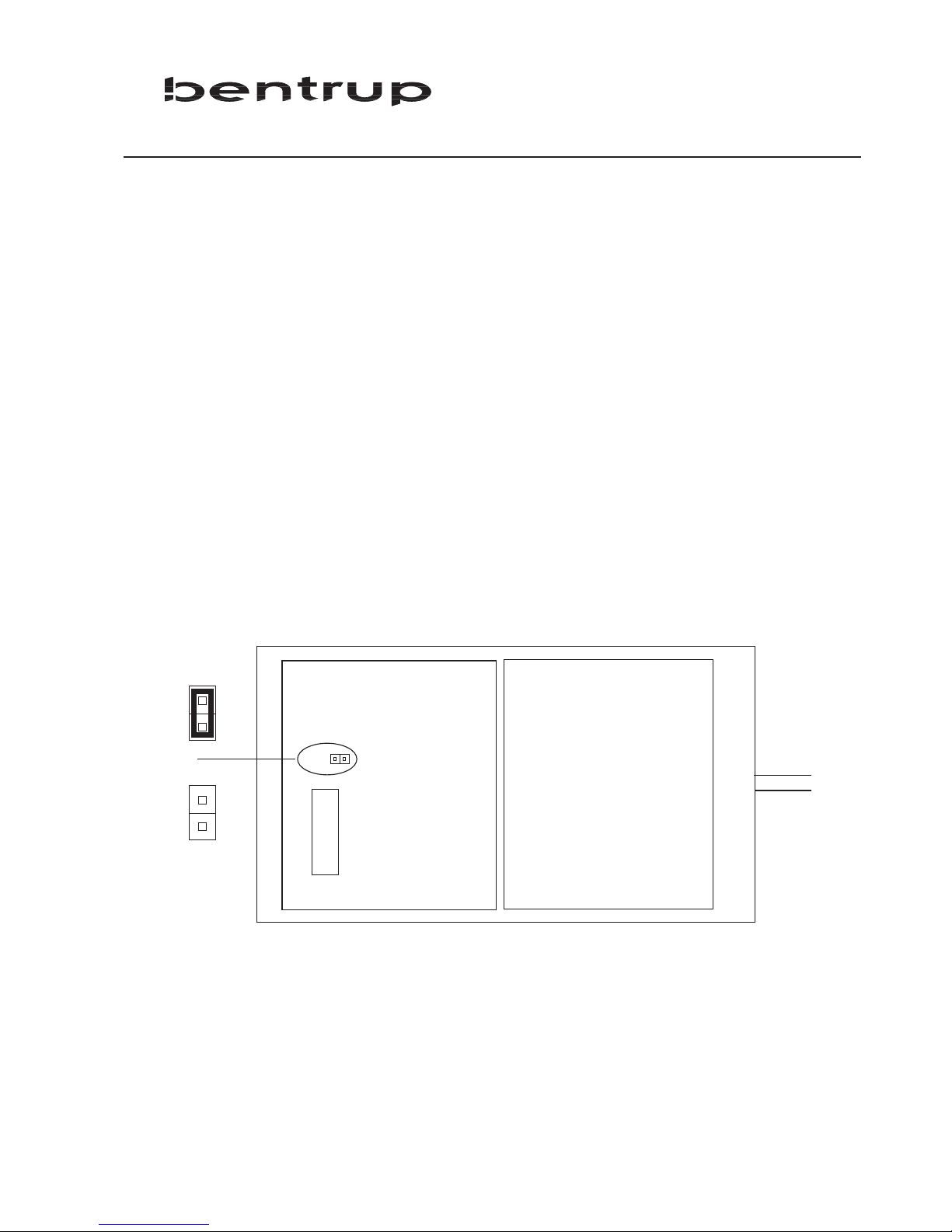
To change the controller to Extended Configuration Mode an internal jumper needs to be set.
Open the controller and located the jumper bridge. Set the jumper as shown
After changing to the Extended Configuration Mode all parameters are set corresponding to the
simple configuration mode. In other words, setting the jumper does not change any operation
mode by itself. However, when you enter the configuration mode the parameter display looks
different as described in the following chapter.
XCFG
Jumper OPEN
(simple configuration)
Jumper CLOSED
(extended configuration)
POSITION OF JUMPER MIGHT
VARY DEPENDING ON MODEL
Page 3
3. Changing Parameters in the Extended Configuration Mode
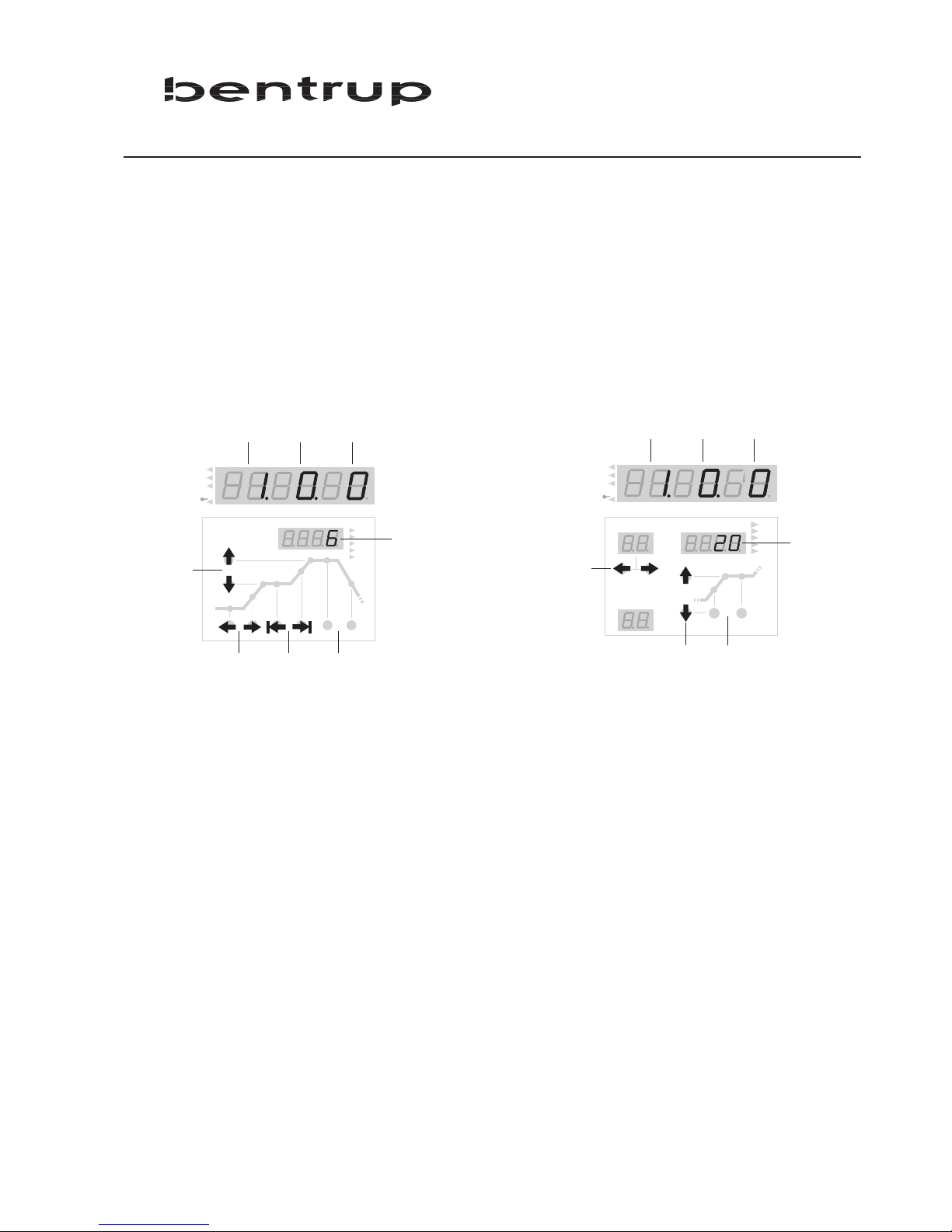
Enter the configuration mode as usually (pess and hold key „select“ until display changes). The
controllers display appears as shown:
TC505 TC507
1 table number 5 keys to select row
2 column number 6 keys to select column / table
3 row number 7 keys to directly select table
4 parameter value 8 keys to change value
The configuration parameters of the TC500 controllers are organized as 12 tables. Every table
specifies one kind of parameter (e.g. table 0=real time clock, table 1=misc. adjustments, ..).
Each row of the table holds one parameter; multiple columns specify settings for repeated
devices (e.g. one column for each control output).
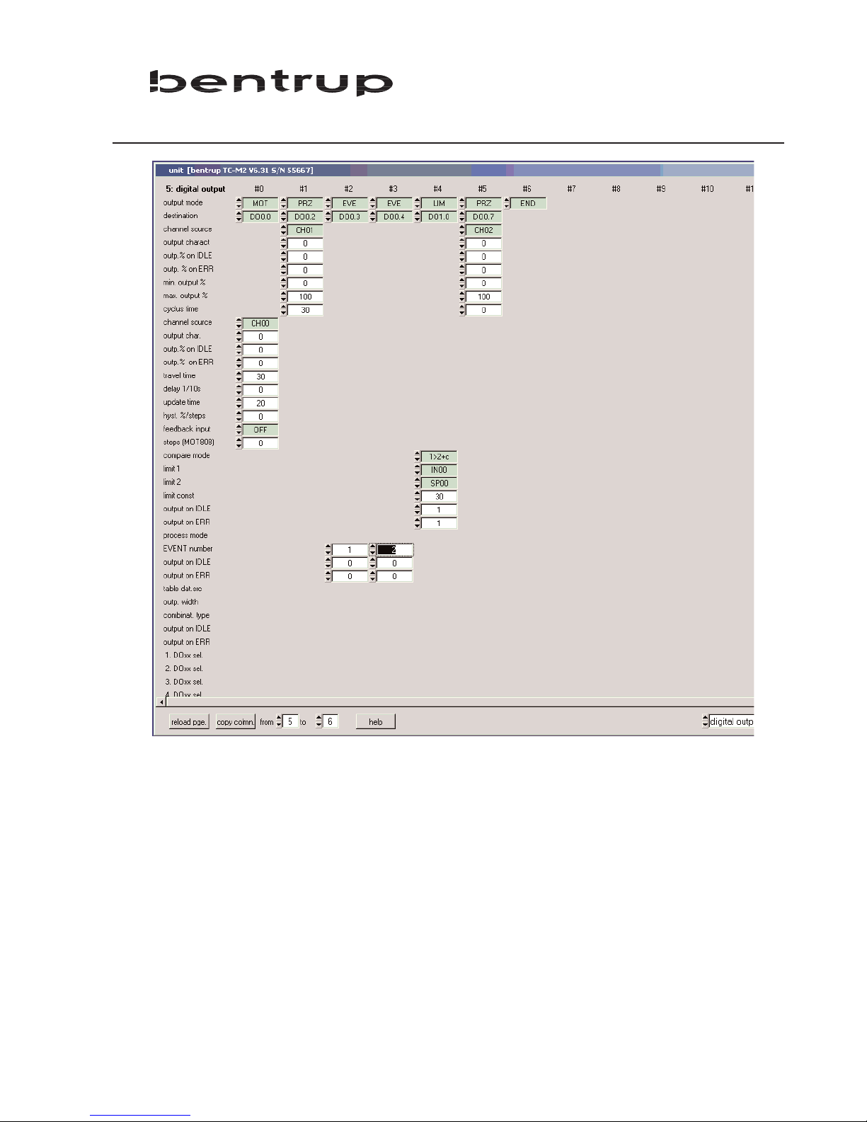
Please find as an example the digital output configuration table (control outputs):
rmp1
rmp2
t
2
rmp3
tmp
1
t
mp
2
+
-
t
1
t
0
°
C/h
h
.min
°
C
°
F/h
°
F
Z
3
Z 1
Z2
1 2 3
4
876
5
tmp
dwell
r
mp
t
ime
°
C/h
h
.min
°
C
°
F/h
°
F
p
rog#
s
eg#
v
alue
Z
3
Z 1
Z2
-
+
1 2 3
4
8
5
6
3
Page 4
4
DO......................digital output (e.g. switching output)
DI........................digital input (e.g. status input)
AO......................analog output (e.g. 0-10V output)
AI........................analog input (e.g. measure input)
The number following this designator specifies the input/output. Examples:
DO 0.0................1st switching output of the controller
DO 0.1................2nd switching output of the controller
AI 0.0..................1st analog input (e.g. thermocouple) of the controller
Page 5

U
se the keys as specified before to navigate through the parameters and modify as requested.
Since also minor changes of the parameters might cause major changes in controller operation
you need to familiarize yourself entirely with the configuration.
To save the changes permanently press and hold the key „select“ and keep it pressed until the
display shows „Sav.OkY“. If you release the key too early (e.g. during „Sav.CfG“) all changes
will be lost! Note: If you get mixed up with the parameter changes at anytime simply turn off
and turn back on the controller to return to the previous parameter settings.
4. Detailed Explanation of all Parameters
All paramters are explained in detail. See file „TC500.html“ (german) or TC500e.html (english)
supplied as a seperate file.
5. Changing Parameters by a PC
If your TC500 controller is fitted with a RS232 or RS485 interface you can use the free bentrup
software WinConfig to do all parameter changes very easy. WinConfig makes parameter setting
simple as well you can save configurations on disk and reload etc.
The RS232 or RS485 interface can be also added to exisiting TC500 controllers at very
reasonable costs. The configuration table shown earlier in this manual is a screenshot from
WinConfig.
6. Returning to Simple Configuration
Simply remove the jumper to return to Simple Configuration Mode. This configuration mode has
priority ie. the TC500 controller will disregard all enhanced configuration mode settings.
7. Changing type of Thermocouple S/R to J/K and vice versa
Usually type of thermocouple should not be changed from S/R to J/K since different
compensating cable is needed. However, if this is considered this change is done by adjusting
the other jumper (marked as „T/C J/K“, see chapter 2.). Note: This only applies if the controller
operates in simple configuration mode. Keep in mind that mismatch of thermocouple and
controller setting causes severe damage to the kiln and goods.
5
Page 6

6
bentrup TC505/507 Configuration Table Version 1.12
Table 0: clock / calender
The controller uses its real time clock / calender for different purposes. It allows the automatic commencing of
programmes at predefined times as well the real time clock / calender is used to time stamp logged data and
events. When configuring the controller using bentrup WinConfig / WinControl the controller is automatically
updated with the PCs time / date information, Therefore manually changeing time / date is disabled
.
00: time (hours)
(value range 00 to 23)
current time (hours) of the real time clock
01: time (minutes)
(value range 00 to 59)
current time (minutes) of the real time clock
02: date (weekday)
(options MON, TUE, WED, THU, FRI, SAT, SUN)
current date (weekday) of the real time calendar
03: date (day)
(value range 01 to 31)
current date (day) of the real time calendar
04: date (month)
(options JAN, FEB, MAR, APR, MAY, JUN, JUL, AUG, SEP, OCT, NOV, DEC)
current date (month) of the real time calendar
05: date (year)
(value range 00 to 99)
current date (year) of the real time calendar
06: cfg.lock level
(value range 0 to 5)
reserved for future used
.
.
Table 1: misc. adjustments
The following miscalleneous adjustments determine general operation parameters of the controller
.
00: max. segments
(value range 5 to 98)
maximum number of segments per programme. Entering a smaller number increases the number of
programmes you can save in your controller. In most applications a maximum of 20 segments is suitable. Note:
After changing this value all programmes must be reentered because of the required reorganisation of the
controllers memory
01: ramp mode(s)
(options TIME, GRAD, BOTH)
Specifies how to define ramps:
TIME: Ramps entered as segment time
GRAD: Ramps entered as gradient (e.g. 200°C/h)
BOTH: Ramps can be entered as segment time as well as gradient
02: prg.end Temp
(value range 20 to 1800)
Defines the temperature the final ramp of the programme is finished. Parameter applies not to TC507
03: manual enable
(options OFF, ON)
Page 7

7
The manual mode allows the user to individually operate the control outputs (digital outputs and analog
outputs) manually. This feature is very helpful for kiln commissioning. Caution: For safety reasons only enable
this MODE if the operator is familiar with it !
04: auto P. starts
(options OFF, ON)
This feature allows automatic commencing programmes by the weekly switching clock. Depending on
configuration up to 99 real time clock / weekdays controlled jobs can be entered. Enable this feature only if
necessary to avoid unintentional programme commencing
05: lock programs
(options OFF, ON)
Allows locking of all programmes (temperature curves) to avoid any unauthorized changes
06: communicat. ID
(value range OFF to 62)
Sets the communication ID of the controller. Affects external communication only. Make sure that this ID fits
the setting in the communcation software (e.g. bentrup WinControl). Each ID must be unique on the
communication network
07: RS485 baudrate
(value range 9600 to 38400)
Baud rate of the communication
08: fctn.on pow.up
(value range 0 to 3)
Verhalten nach dem Einschalten: 0=Regler aus (IDLE), 1/2=automatischer Programmstart wenn alle
Bedingungen erfüllt sind (1=Zeit-Limit in Sekunden / 2=Zeit-Limit in Minuten). 3=automatischer Programmstart
09: ..only if Dxx
(value range OFF to 5)
Programme is continued only if the selected output was ON before power breakdown. When selecting and
output controlled by a programme EVENT, this feature can be used to enable programme continuation after a
power breakdown for each segment
10: only if t<time
(value range -1 to 240)
Programme is continued only if the duration of the power failure was less than this parameter. Depending on
the selection of "fctn. on pow. up" this time limit is seconds or minutes
11: dT input sel
(value range OFF, IN00 to IN03)
Selects the process value check for drop in temperature during a power breakdown
12: ..only if dT<x
(value range -9999 to 9999)
Programme is continued only if the selected process value did not drop more than a the given value during
power breakdown
.
Page 8

8
.
Table 2: analog input
Specifies the analog input signals for the controller. Analog inputs are used to connect sensors like
thermocouples, resistors, voltage/current signals to the controller. You can exactly define signal type (voltage,
resistance, current) as well as signal range, signal conversion and correction, unit etc. The most common signal
types are predefined. Each column of the table defines one process value which are named IN00, IN01 etc. The
maximum number of analog input depends on the hardware.
.
00: input mode
(options END, T/C, LIN, ATMS, RES)
type of the analog input signal. Choose the appropriate kind of signal conversion from the given options:
T/C: Thermocouple input type. Selection of thermocouple and compensation mode see parameter below
LIN: Linear input type for generic use. This mode is used to convert any kind of linear input signal (as defined in
the corresponding parameters) into its process parameter. An example for a typical application is to convert a
4-20mA signal from a pressure transducer into 0 to 100 Pa process parameter
ATMS: Atmosphere signal conversion. Use this selection to convert the typical signal of a circonoxyde probe
into the kiln atmosphere reading. The controller uses the equation of Nerntzsch to convert the probe signal
into % of oxygen. The probe temperature required for oxygen calculation is specified in the corresponding
parameters as well as the kind of gas required for the carbonmonoxyde calculation. Note below on
temperatures below 650°C no oxygen calculation is done (no reliable probe signal)
RES: Resistance temperature sensor conversion. Converts the resistance characteristic of most commonly used
resistance sensors (like Pt100) into temperature reading
01: signal source
(value range AI0.0 to AI1.0)
Specifies a physical input (AI..) of the controller. The process parameter is created from the signal on this
physical input. To create two different process parameters from one physical input make sure that both signal
types and ranges equals
02: average cycles
(value range 1 to 11)
Specifies the low pass signal filter. This options is used to smoothen the input signal. Can be used to eliminate
signal interference as well as to improove signal quality. Setting this option to "1" disables the filter. A higher
setting causes higher smoothening (low pass frequency is 1/n Hz). A setting of 4 suits most applications.
03: units
(options °C, °F, °K, dg, mV, mA, O2, CO, %, ev, mb, m³, m³h, kh, kwh, Pa, AT)
Specifies the unit of the process value
04: trim +/- %
(value range -10.0 to 10.0)
Allows full scale input signal correction. In certain applications it is required to compensate for any deviations
of the installation. Example: Setting this parameter to -5.0% will cause the process value to be trimmed to 95°C
instead of 100°C. Note: This parameter should be used with care since on most applications deviations errors
should to be compensated by eliminating the real cause of the deviation rather then compensating on the
controller
05: offset +/- val
(value range -10.0 to 10.0)
Allows zero offset signal correction. Adjust this parameter if you need to adjust the input offset value. Note:
This parameter should be used with care since on most applications deviations errors should to be
compensated by eliminating the real cause of the deviation rather then compensating on the controller
06: min value
(value range -9999 to 9999)
Minimum value of the process value. Specifies the lower value limit of the process parameter. Any lower value
is respected as underrun (causing an error)
07: max value
(value range -9999 to 9999)
Maximum value of the process value. Specifies the upper value limit of the process parameter. Any higher
Page 9

9
value is respected as overrun (causing an error)
following parameters apply on selection T/C only:
08: thermocouple
(options S, R, K, J, B)
Select the IEC code of the thermocouple used
09: external CJC
(value range OFF, IN00 to IN03)
Could junction compensation temperature. Set to "OFF" for internal compensation (recommended). Make sure
that the proper compensating wire is used
following parameters apply on selection LIN only:
18: signal type
(options OFF, 0-20mV, 0-50mV, 0-5V, 0-10V, 0-20mA, 4-20mA, -500R2, 500R3)
Type of input signal. Set this parameter to fit the signal of the device connected to the physical input. Note:
Adapt the jumper settings of the physical input accordingly (done automatically on some devices)
19: val.@zeropoint
(value range -2000.0 to 2000.0)
Process value at lower reference of input value. Example: A pressure transducer supplying 4 to 20mA at -250 to
+250 Pa. Set this parameter to "-250" since this is the process value at the lower reference of 4mA
20: val.@fullscale
(value range -2000.0 to 2000.0)
Process value at upper reference of input value. Example: A pressure transducer supplying 4 to 20mA at -250 to
+250 Pa. Set this parameter to "250" since this is the process value at the upper reference of 20mA
following parameters apply on selection ATMS only:
28: temp. source
(value range IN00 to IN03)
Selects the process value representing the temperature of the atmosphere sensor. The temperature is required
for the calculation of the oxygen
29: min. CO temp
(value range 600 to 1800)
Minimum temperature in centigrade Kelvin required for carbonmonoxyde calculation. A minimum
temperature of 900°C (1273°K) is recommended for reliable calculation
30: press.source
(value range OFF, IN00 to IN03)
Selects the process value representing the over pressure of the reference air. This is used to supervise the
referece air for the oxygen probe. Set to "OFF" if not used
31: min. pressure
(value range 0 to 250)
Minimum pressure limit of reference air. Oxygen process value is set to "INVALID" if reference over pressure
falls below this limit
32: type of gas
(options NATGAS, PROPAN, BUTHAN)
Kind of the gas used. This selection is only used for calculating carbonmonoxyde
following parameters apply on selection RES only:
38: resist.type
(options PT100)
Kind of the resistance sensor used
39: signal type
(options -500R2, -500R3)
Type of input signal. Set this parameter to fit the signal of the device connected to the physical input. Note:
Adapt the jumper settings of the physical input accordingly (done automatically on some devices)
.
Page 10

10
.
Table 3: digital input
Digital inputs can be used for different purposes. First they are used to create a process value depending on a
frequency or number of pulses. Second they are used to control programme execution in different ways. Third,
they are used by the optional PLC. Note: PLC provides you with total flexibility of the controller. If you are using
the PLC of the controller you must not do any adjustments in this digital input section since all features are
programmed by PLC networks
.
00: input mode
(options END, CNT)
Sets the operation mode of the digital inputs. Set to END when using the PLC
CNT: Pulse signals supplied to this input are converted into a process value. Obsolete feature
01: signal source
(value range DI0.0 to DI1.0)
Physical input used for the function
02: units
(options °C, °F, °K, dg, mV, mA, O2, CO, %, ev, mb, m³, m³h, kh, kwh, Pa, AT)
no explanation available
03: min value
(value range -9999 to 9999)
no explanation available
04: max value
(value range -9999 to 9999)
no explanation available
following parameters apply on selection CNT only:
05: count unit x /
(value range -2000.0 to 2000.0)
no explanation available
06: count unit / x
(value range -2000.0 to 2000.0)
no explanation available
.
.
Table 4: analog output
Analog outputs are used to drive of analog devices like steady power control units (thyristor controls), voltage
controlled frequency converters or any kind of recorders. The analog output can be any kind of voltage (0 to
10V etc.) or current (0-20mA etc.) signal. The controller can be configured to drive an analog output by any
kind of process value (control channel output, process value output etc.)
.
00: output mode
(options END, PRZ, ANA)
Sets the operation mode of the analog output:
PRZ: Sets the analog output to be used to send the channel output value for controlling the heating resp.
cooling device. Example: Use this mode to provide a 4-20mA steady output signal (according to 0 to 100%
heating) for driving a thyristor
ANA: Sets the analog output to send any internal process value as analog signal within adjustable boundaries.
Example: Use this mode to create a 0 to 10V output signal according to 0°C to 1000°C programme setpoint
01: output type
(options OFF, 0-20mV, 0-50mV, 0-5V, 0-10V, 0-20mA, 4-20mA)
Signal type. Note that changing from voltage to current mode (and vice versa) requires adapting the jumper
Page 11

11
settings resp. reconnecting the outlets to a different position
02: destination
(value range AO0.0 to AO0.2)
Selects the physical output of the signal
following parameters apply on selection PRZ only:
03: channel source
(value range CH00 to CH02)
Selects the control channel (loop) used to drive the output. The options MX../A resp. MX../G are the outputs of
the air / gas mixer (for combustion units)
04: output charact
(value range 0 to 4)
Specifies the operation range of the output. Used to limit an output assigned to a heating / cooling loop (range
+100% to -100%) to the physical range of operation. In an typical application one output (eg. controlling the
heating elements) is set to "0 to +100%" and a 2nd output (eg. controlling a fan) is set to "0 to -100%" (both
outputs assigned to the same control channel). The available settings are 0=0% to +100% / 1=+100% to 0% /
2=0% to -100% / 3=-100% to 0% / 4=-100% to +100% / 5=+100% to -100%
05: outp.% on IDLE
(value range 0 to 100)
Whenever the controller is IDLE the output is fixed to this value
06: outp. % on ERR
(value range 0 to 100)
Whenever the entire controller is in ERROR status the output is fixed to this value. Note that this only applies
on system errors and not an operation error on a single channel
07: min. output %
(value range 0 to 100)
Lower output signal limit. The output will never drop below this limit. Can be used for instance to obtain
permanent minimum heating. Care should be taken since high settings might interfere with the control loop
08: max. output %
(value range 0 to 100)
Upper output signal limit. The output will never exceed this limit. Can be used for instance to limit the
maximum heating of a kiln. Note that limiting can cause problems if the applications lacks of heating power
(gradient check errors etc.)
following parameters apply on selection ANA only:
13: outp. param.
(value range SP00 to CH19)
Selects a process value sent to the analog output. The output is driven according to to the process value in the
range given by the following parameters "lower base value" and "upper base value". Example: Assuming a
signal type 0 to 10V / lower base value 0°C / upper base value 1000°C the output provides 7,5 V on a process
value of 750°C
14: lower base val
(value range -9999 to 9999)
Sets the lower base value for a process value output. For details refer to the example given at "outp. param."
15: upper base val
(value range -9999 to 9999)
Sets the upper base value for a process value output. For details refer to the example given at "outp. param."
Page 12
12
.
Table 5: digital output
Digital outputs are used to switch any kind of ON/OFF devices as well as motorized valves (using 2 digital
outputs in sequence). Depending on controller hardware the output is either a switching relay output (8A /
250V) or a logic output (OFF=0V / ON=12V). The following parameters select the kind of operation (control
outputs, alarms, events etc.). Digital outputs used by the PLC must not be assigned in this section
.
00: output mode
(options END, PRZ, MOT, LIM, PRC, EVE, TAB, CMB, ---)
Selects an operation mode of the digital outputs:
PRZ: Used to provide the output value of a control channel (loop) to an ON/OFF device. The most common
application is to control a contactor used for heating
MOT: Used to provide the output value of a control channel (loop) to a servomotor device. A typical application
when controlling a motorized butterfly valve on a gas kiln. A servomotor is controlled by 2 digital outputs
(OPEN and CLOSE). The physical output CLOSE is automatically assigned to the output following OPEN
LIM: Output works as limit switch (commonly called ALARMs). Any kind of comparison of process of constant
values can be done
PRC: Indication of selectable process conditions. Can be used to activate an output on programme end, process
errors, process holds etc.
EVE: Used to configure the output as programme event. Can be programmed to ON or OFF for each segment.
During programme run the output is set accordingly
TAB: Used to control a group of outputs according to the bit pattern provided in the corresponding column of
the programme table. Typically used in combination with a PLC
CMB: Output is driven according to the result of the network defined by the following parameters. Used to
create simple logic networks, ie. output do0.2 is only if do1.0 and do1.1 is active. For more complex networks
ask for the optional, integrated PLC
01: destination
(value range OFF, DO0.0 to DO0.4)
Selects the physical output of the signal
following parameters apply on selection PRZ only:
02: channel source
(value range CH00 to CH02)
Selects the control channel (loop) used to drive the output
03: output charact
(value range 0 to 5)
Specifies the operation range of the output. Used to limit an output assigned to a heating / cooling loop (range
+100% to -100%) to the physical range of operation. In an typical application one output (eg. controlling the
heating elements) is set to "0 to +100%" and a 2nd output (eg. controlling a fan) is set to "0 to -100%" (both
outputs assigned to the same control channel). The available settings are 0=0% to +100% / 1=+100% to 0% /
2=0% to -100% / 3=-100% to 0% / 4=-100% to +100% / 5=+100% to -100%
04: outp.% on IDLE
(value range 0 to 100)
Whenever the controller is IDLE the output is fixed to this value
05: outp. % on ERR
(value range 0 to 100)
Whenever the entire controller is in ERROR status the output is fixed to this value. Note that this only applies
on system errors and not an operation error on a single channel
06: min. output %
(value range 0 to 100)
Lower output signal limit. The output will never drop below this limit. Can be used for instance to obtain
permanent minimum heating. Care should be taken since high settings might interfere with the control loop
07: max. output %
(value range 0 to 100)
Page 13
13
Upper output signal limit. The output will never exceed this limit. Can be used for instance to limit the
maximum heating of a kiln. Note that limiting can cause problems if the applications lacks of heating power
(gradient check errors etc.)
08: cyclus time
(value range 0 to 100)
Cyclus time (in seconds) of the digital output. The output value is converted into an ON and OFF period
accordingly (T on + T off = T cyclus). Decreasing the cyclus time improves accuracy but might decrease lifetime
of the heating device. A typical value for contactors on kilns is 30
following parameters apply on selection MOT only:
12: channel source
(value range CH00 to CH02)
Selects the control channel (loop) used to drive the output
13: output char.
(value range 0 to 5)
Specifies the operation range of the output. Used to limit an output assigned to a heating / cooling loop (range
+100% to -100%) to the physical range of operation. In an typical application one output (eg. controlling the
heating elements) is set to "0 to +100%" and a 2nd output (eg. controlling a fan) is set to "0 to -100%" (both
outputs assigned to the same control channel). The available settings are 0=0% to +100% / 1=+100% to 0% /
2=0% to -100% / 3=-100% to 0% / 4=-100% to +100% / 5=+100% to -100%
14: outp.% on IDLE
(value range 0 to 100)
Whenever the controller is IDLE the output is fixed to this value
15: outp.% on ERR
(value range 0 to 100)
Whenever the entire controller is in ERROR status the output is fixed to this value. Note that this only applies
on system errors and not an operation error on a single channel
16: travel time
(value range 0 to 250)
Enter the time (in seconds) for the servomotor to move over the entire actual operation range (fully close to
fully open)
17: delay 1/10s
(value range 0 to 150)
Delay time of the servomotor on direction changes. This parameter (given as 100ms units) is used to
compensate for gearbox lags etc.
18: update time
(value range 0 to 250)
Rate in seconds the servomotor position is updated. Decreasing this rate causes more stress to the servomotor
19: hyst. %/steps
(value range 0 to 100)
Hysteresis for updating the servomotor position. Decreasing this rate causes more stress to the servomotor.
However, in most application a hysteresis of 1% is recommended
20: feedback input
(value range OFF, IN00 to IN03)
The position feedback option is used for best tracking of the actual servomotor position. Typically a position
potentiometer is connected to an analog input (configured as linear resistance input 0-100%). Enter the
process parameter number of this input here. Set to OFF is unused
21: steps (MOT808)
(value range -9999 to 9999)
no explanation available
following parameters apply on selection LIM only:
22: compare mode
(options 1>2+c, 1<2+c, dif<c, dif>c)
Selects the kind of equation of the formula given as limit 1 ? limit 2 + limit const. The "?" is replaced depending
on this parameter: 0 stands for ">=", 1 stands for "<=", 2 means "limit 1 - limit 2 less then limit const", 3 means
"limit 1 - limit 2" more than limit const. The digital output is ON when the equation is true. Example: To activate
the output whenever the actual temperature exceeds the setpoint more than 30°K (= overtemperature alarm)
Page 14

14
set the parameters as follows: compare more = 0 / limit 1 = IN00 / limit 2 = SP00 / limit const = 30
23: limit 1
(value range OFF, SP00 to CH19)
Selects the process value used as "limit 1" in the formula. This can be a setpoint, an actual temperature, a
channel (loop) output or "OFF" to insert "0" in the formula. For detailed explanation including an example refer
to "compare mode"
24: limit 2
(value range OFF, SP00 to CH19)
Selects the process value used as "limit 2" in the formula. This can be a setpoint, an actual temperature, a
channel (loop) output or "OFF" to insert "0" in the formula. For detailed explanation including an example refer
to "compare mode"
25: limit const
(value range -9999 to 9999)
The constant value used as "limit const" in the formula. For detailed explanation including an example refer to
"compare mode"
26: output on IDLE
(value range 0 to 2)
Defines the state of the digital output when the controller is IDLE: 0 = same as during programme run / 1 = OFF
/ 2 = ON
27: output on ERR
(value range 0 to 2)
Defines the state of the digital output when the controller enters a system error: 0 = same as during
programme run / 1 = OFF / 2 = ON
following parameters apply on selection PRC only:
32: process mode
(value range 0 to 18)
Selects the process state the digital output is indicating: 0=programme run (also ON during segment 0 and at
the end of the firing) / 1=programme run (also ON during segment 0) / 2=programme run / 3=end of the firing /
4=any channel error / 5=programme HOLD / 6=OFF / 7=ON / 10/11/12=mixer in air
excess/stochiometric/cooling mode / 13=programme continues after power breakdown / 14=do0.6 and not
do0.7 / 15=do0.6 and do0.7 / 16=not do0.6 and do0.7 / 17=control channel off band / 18=programme
interrupted due to off band / 19=any monitored channel error / 20=final temperature matches in all monitored
channels / 21=any monitored channel in control range / 22=any monitored channel out of control range
following parameters apply on selection EVE only:
42: EVENT number
(value range 0 to 10)
Digital output works as programme EVENT number #. This number must fit the EVENT number specified in the
programme table
43: output on IDLE
(value range 0 to 1)
Defines the state of the digital output when the controller is IDLE: 0 = OFF / 1 = ON
44: output on ERR
(value range 0 to 1)
Defines the state of the digital output when the controller enters a system error: 0 = same as during
programme run / 1 = OFF / 2 = ON
following parameters apply on selection TAB only:
52: table dat.src
(value range TA00 to TA04)
Select the column number of the programme table the programme value is taken
.
Page 15

15
.
Table 6: programme table
The programme table determines the parameters and the sequence to be entered for each programme
segment. The first programme parameter is always a time followed by a temperature. Depending on the
application the following programme segment parameters could be for instance offset temperatures (for
multizone kilns), programme events etc. The parameter sequence after the 1st temperature is variable;
however, keeping all programme EVENTs togather saves programme memory
.
00: value type
(options END, TIME, VAL-L, ---, VAL-S, EVENT, ATMS)
Select the kind of value in each column of the programme table:
TIME: The very first column of the programme table holds the segment time
VAL-L: Programme value in the range of -10000 to 10000. Typically used for any kind of absolute value (like kiln
temperature etc.)
---: selection not used
VAL-S: Programme value in the range of -127 to 128. Typically used for any kind of relative values (like offset
temperature for zones)
EVENT: EVENT value, ie. holds ON or OFF. When requiring multiple events defining them one after the other
saves programme memory
ATMS: Programme value to define an atmosphere
01: designator
(alphanumerical characters)
Used to give each programme table column an individual name (consisting of up to 3 alphanumeric letters)
following parameters apply on selection TIME only:
02: lower time lim
(value range -101 to 0)
Limits the value range entered as a time. Note that the values smaller than minus 2 enable the programme link
feature (-3 = allow linking to programme number 1, -4 = allow linking to programme number 2 etc.)
03: upper time lim
(value range 1 to 5999)
Upper limit when adjusting the time. The 1000 steps beyoind this limit stand for setting the gradient as
centigrade kelvin per period
following parameters apply on selection VAL-L only:
12: value unit
(options °C, °F, °K, dg, mV, mA, O2, CO, %, ev, mb, m³, m³h, kh, kwh, Pa, AT)
Specifies the unit of the programme table value
13: lower val. lim
(value range -9999 to 9999)
Lower limit of the programme table value. Used for instance to ensure the values entered by the user stay
within the operation limits of the kiln
14: upper val. lim
(value range -9999 to 9999)
Upper limit of the programme table value. Used for instance to ensure the values entered by the user stay
within the operation limits of the kiln
following parameters apply on selection --- only:
22: value unit
(options °C, °F, °K, dg, mV, mA, O2, CO, %, ev, mb, m³, m³h, kh, kwh, Pa, AT)
Specifies the unit of the programme table value
23: lower val. lim
(value range -9999 to 9999)
Lower limit of the programme table value. Used for instance to ensure the values entered by the user stay
within the operation limits of the kiln
Page 16

16
24: upper val. lim
(value range -9999 to 9999)
Upper limit of the programme table value. Used for instance to ensure the values entered by the user stay
within the operation limits of the kiln
following parameters apply on selection VAL-S only:
32: value unit
(options °C, °F, °K, dg, mV, mA, O2, CO, %, ev, mb, m³, m³h, kh, kwh, Pa, AT)
Specifies the unit of the programme table value
33: lower val. lim
(value range -128 to 127)
Lower limit of the programme table value. Used for instance to ensure the values entered by the user stay
within the operation limits of the kiln
34: upper val. lim
(value range -128 to 127)
Upper limit of the programme table value. Used for instance to ensure the values entered by the user stay
within the operation limits of the kiln
following parameters apply on selection EVENT only:
42: EVENT number
(value range 0 to 2)
This unique number identifies the EVENT in the programme table for the digital output
following parameters apply on selection ATMS only:
52: atmosphere cde
(options AT)
Wählt die Einstellungsart des Atmosphären-Sollwertes aus. Wert nicht veränderbar
.
.
Table 7: process flow
The parameters of this section specify the reaction of the controller to any kind of unusual conditions that
might happen during a programme run. Examples for unusual conditions are broken temperature sensors, heat
up problems of the kiln, control channel errors etc. As well the conditions to enter the next segment during a
running programme can be adjusted as required
.
00: time in ramps
(options KEEP, UPDAT)
If the temperature of the pilot input (IN00) is higher than the start temperature of the ramp the time of the
ramp can be either kept or reduced accordingly
KEEP: Segment time is kept, setpoint begins as programmed
UPDAT: Segment time is reduced accordinly. Example: Segment 0 is 0°C, segment 1 is "in 2 hours to 500°C".
Assuming a kiln temperature of 250°C when starting the firing, the time is reduced to 1 hour (causing a setpoint
of 250°C)
01: monitor ch
(value range -CH02 to CH02 )
Only the channels specified are monitored for process problems. This setting allows to include only the
channel(s) which are important for the process. Either a single channel can be selected (e.g. on single zone
kilns) or a range of channels (e.g. ch00 to ch02 on a 3 zone kiln). A range is entered as minus channel (e.g. "ch02" stands for ch00 to ch02)
02: temp match %o
(value range 0.0 to 100.0)
An uncontrolled ramp (SKIP) the end of the segment is determined by match of actual temperature and final
segment temperature. Since the controller slows down temperature move at the end to avoid
over/undershoot it might take some time to finally reach the temperature althought it is not required by the
process. This parameter allows to specify a window to earlier complete the segment. Example: 2.0 ppm of
1320°C (max. channel temperature) = 2.64°C, SKIP segment ends at 997.36°C assuming a final ramp
Page 17

17
temperature of 1000°C
03: num of matches
(value range 1 to 250)
An uncontrolled ramp (SKIP) is only completed if the temperature matched the specified number of cycles. The
check is done each 0.5 seconds. This is used to avoid leaving the segment if the temperature only overshoots
for a short time. Example: The setting of 6 lets the controller to complete the current segment if the
temperature matched for at least 3 seconds
04: end of SKP seg
(options DISR, WAIT.X, INFIN)
An uncontrolled ramp (SKIP) usually is only completed if the actual temperature reached the final ramp
temperature. The following options are considered:
DISR: Causes the controller to disregard the temperature, ie. to leave a SKIP segment immediately
WAIT.X: Causes the controller to wait for temperature match, but maximum for the specified time (see next
parameter). This option is strongly recommended on multi zone kilns, e.g. at a time of 10 minutes. Otherwise
the process might lock up itself. For instance in a cooling SKIP, the thermocouple of zone 2 has a little deviation
an therefore zone 2 is heated 4°C higher; if the heating affects zone 1 this zone will never cool down as
neccessary. The time begins to count if the first zone starts to control. If the time is elapsed the segment is
finished disregarding the temperature of the zones matches
INFIN: Causes the controller to wait for temperature match for infinite time
05: max wait (sec)
(value range 0 to 9999)
wait time in seconds for the feature specified previously
06: act.on CH unco
(options DISR, WAIT.BR, WAIT.CO, INFI, INFI, INFI)
In a controlled ramp it might happen that the kiln temperature can not follow the requested increase although
the controller asks for maximum heating (resp. the requested decrease in a cooling segment). The following
actions can be selected:
DISR: Causes the controller to disregard this situation
WAIT.BR: Causes the controller to hold the firing to give the kiln temperature time to catch up. If the kiln
couldn't catch up within the specified time (see next parameter) the firing is interrupted (break). The hold
mode (same as hold used during programme run) can also be released manually by pressing the hold skip
button
WAIT.CO: Bei dieser Einstellung hält der Regler den Brennvorgang ebenfalls an, führt den Brennvorgang aber
nach der eingestellten Zeit fort, wenn die Temperatur nicht aufholt wird
INFI: Causes an immediate break if the temperature can not follow.
07: max hold (sec)
(value range 0 to 9999)
wait time in seconds for the feature specified previously
08: uncontr = ..CH
(options ALL, ANY)
Selects the criteria the controller judges to the kiln as non following the temperature increase:
ALL: all channels out of control (maximum or minimum heating)
ANY: any channel out of control
.
Page 18
18
.
Table 8: programme setpoint
The programme setpoints are calculated according to the programme resp. temperature curve entered by the
operator. Some adjustments are possible for easy operation. Automatic setpoint calculation required for
cascade control systems is also entered by the following settings
.
00: setpoint type
(options END, CON, MOD, CHA)
The following basic types creating a setpoint can be selected:
CON: Use initial value of the programme segment only. Typical applications are offset values for zone
temperatures or flap positions
MOD: Programme setpoint modulated by the segment time. This is the common setting causing the
programme setpoint to count upwards resp. downwards over the segment time (e.g. within 2:00 hours from
0°C up to 1000°C)
CHA: Setpoint calculated by cascade control algorithm - for details refer to the example below
following parameters apply on selection CON only:
01: table source
(value range CH/Z2 to TA04)
Selects the column of the programme table used for setpoint calculation. TA01 is the 1st column, ie. usually the
primary temperature
02: offset src SP
(value range OFF, SP00 to SP02)
Defines a setpoint which refers to an existing setpoint, ie. the setpoint is calculated by adding another setpoint
to it. Used e.g. for the setpoint of the slave zones of a multizone kiln. Using this option allows the operator to
enter the temperature of the slave zones as offset (temperature difference) relative to the master zone
setpoint. In this example the master zone setpoint is entered in this option
03: idle setpoint
(value range -9999 to 9999)
Setpoint whenever the controller is not in a programme run (IDLE). Can be used to ensure a certain
temperature is maintained without a programme run. Entering "0" switches off this feature
04: error setpoint
(value range -9999 to 9999)
Setpoint whenever the controller is not in a programme run (IDLE). Can be used to ensure a certain
temperature is maintained without a programme run. Entering "0" switches off this feature
following parameters apply on selection MOD only:
11: table source
(value range CH/Z2 to TA04)
Selects the column of the programme table used for setpoint calculation. TA01 is the 1st column, ie. usually the
primary temperature
12: offset src SP
(value range OFF, SP00 to SP02)
Defines a setpoint which refers to an existing setpoint, ie. the setpoint is calculated by adding another setpoint
to it. Used e.g. for the setpoint of the slave zones of a multizone kiln. Using this option allows the operator to
enter the temperature of the slave zones as offset (temperature difference) relative to the master zone
setpoint. In this example the master zone setpoint is entered in this option
13: idle setpoint
(value range -9999 to 9999)
Setpoint whenever the controller is not in a programme run (IDLE). Can be used to ensure a certain
temperature is maintained without a programme run. Entering "0" switches off this feature
14: error setpoint
(value range -9999 to 9999)
Setpoint whenever the controller is not in a programme run (IDLE). Can be used to ensure a certain
temperature is maintained without a programme run. Entering "0" switches off this feature
Page 19

19
following parameters apply on selection CHA only:
21: based on SP
(value range SP00 to SP02)
Selects the programme setpoint used for the cascade control, ie. the programme setpoing for the target
22: charg.ctrl.CH
(value range CH00 to CH02)
Selects the master control channel (loop). The basic idea of a cascade control is as follows: An application
requires a large target (e.g. a piece of aluminium) to follow a temperature curve. An appropriate solution is
using an air convection kiln. Using an ordinary control it will give different problems depending on the position
of the thermocouple: When sensing the ambient temperature the actual temperature of the target
(aluminium) will be far (might be even hundreds of degrees centigrade) behind since it is very lag. Sensing the
target temperature might cause damage to the kiln since the controller does not pick up the temperature of
the heaters. Additionally, temperature oscillations are likely when the target temperature is getting close. A
cascade control eliminates these problems and works as follows: Two control channels are combined. The
master control channel is configured as normal, ie. using the programme temperature as setpoint and the
target temperature as actual temperature. The output of this channel is used to create a 2nd temperature
setpoint according to the settings in this section. This setpoint and the actual ambient temperature are
assigned to the slave control channel driving directly the heating device of the kiln. Note that the master
control channel is configured as heating/cooling loop with a wide proportional range and slow integral time
(P/I/D = 10.0% / 400 s / 0 s)
23: max. temp.diff
(value range -9999 to 9999)
Limits the maximum difference in temperature between the target and the ambient temperature. Used to
avoid damage of the target if sensitive. A high limit, however, speeds up the process of the target reaching the
programme setpoint
24: max envir.temp
(value range -9999 to 9999)
Limits the maximum ambient temperature. Used to avoid damage of the target if sensitive. A high limit,
however, speeds up the process of the target reaching the programme setpoint
.
.
Table 9: control channel
The control loops are designed to operate in totally different modes. Each operation mode can be tuned
individually
.
00: ctrl.algorithm
(options END, PID, C-PID, D-HYS, P-DIR, ---)
Depending on your application different control algorithms are available
PID: Default control algorithm suitable for most applications
C-PID: As before, but provides independent disable feature for heating and cooling range. Important on
heating/cooling applications where heating and cooling depends on external conditions. Also used to avoid
heating and cooling ranges chasing each other. Activation is done by any bit (e.g. a digital output). Typical
applications are gas kilns where heating range (0 to +100%) is disabled once the burner control bit goes OFF
D-HYS: Hysteresis control for heating devices which require either temperature deviation or do not allow short
cyclic activation (e.g. discontinuous burners)
P-DIR: Direct control. The setpoint is directly converted into a control value refering to the given value
boundaries. Typical application is setting a flap position directly (e.g. 0 to 100%)
01: setpoint chn
(value range SP00 to CH19)
Selects the setpoint used for this control channel
02: input chn
(value range SP00 to CH19)
Selects the process value used for this control channel
Page 20
20
03: power % on ERR
(value range -100 to 100)
Predefined process output if an error occurs in the control channel. The control channel enters error state if a.)
the process value fails (overrun, underrun, invalid), b.) the process value exceeds the process value limit
specified in the channel configuration or c.) the gradient check indicates failure
04: maximum value
(value range 0 to 9999)
Maximum process value. Used to limit the process input value for safety reasons as well as setting the
operation range. If the process value exceeds the limit the control channel enters error state which can only be
cleared by re-starting the programme. Set this value above the actual operation range to allow overshooting
05: grdnt check s
(value range 0 to 3600)
The gradient check is used for safety reasons. Prevents the unit from damage if the feedback signal (e.g. the
thermocouple) fails. Checking the increase of the process value is performed on maximum output (typically
+100%). This parameter defines the checking period in seconds. Set to "0" to disable checking. If the gradient
check determines an error the channel is switched off (gradient error state)
06: grdnt chk dif
(value range 0 to 9999)
Increase of the process value required per checking period on maximum heating
07: ctrl charact
(value range 0 to 3)
Depending on the application select the operation range of the control channel to one of the following options:
0 = 0% to 100% / 1 = 100% to 0% / 2 = -100% to +100% / 3 = +100% to -100%
following parameters apply on selection PID only:
08: prop. band %
(value range 0.0 to 999.9)
Control parameter "proportional band" in % of the maximum value
09: integral time
(value range 0 to 9999)
Control parameter "integral time" in seconds
10: derivat. time
(value range 0 to 9999)
Control parameter "derivative time" in seconds
11: prop. shift
(value range 0 to 4)
Determines the operating range of the proportional band: 0 = prop. band below setpoint / 1 = prop. band one
quarter above setpoint / 2 = .. half above setpoint / 3 = .. three quarters above setpoint. In most applications a
setting of "1" ensures best results (ie. fast reaching the setpoint with minimum overshoot)
following parameters apply on selection C-PID only:
18: prop. band %
(value range 0.0 to 999.9)
Control parameter "proportional band" in % of the maximum value
19: integral time
(value range 0 to 9999)
Control parameter "integral time" in seconds
20: derivat. time
(value range 0 to 9999)
Control parameter "derivative time" in seconds
21: prop. shift
(value range 0 to 4)
Determines the operating range of the proportional band: 0 = prop. band below setpoint / 1 = prop. band one
quarter above setpoint / 2 = .. half above setpoint / 3 = .. three quarters above setpoint. In most applications a
setting of "1" ensures best results (ie. fast reaching the setpoint with minimum overshoot)
22: + activat. DOx
(value range OFF, DO0.0 to DO1.0)
Selects the bit (digital output) which activates the positive operation range (heating). When the bit is off the
Page 21

21
channel enters OFF status as long as heating applies
23: - activat. DOx
(value range OFF, DO0.0 to DO1.0)
Selects the bit (digital output) which activates the negative operation range (cooling). When the bit is off the
channel enters OFF status as long as cooling applies
following parameters apply on selection D-HYS only:
28: hyster. units
(value range 0.0 to 100.0)
Hysteresis of the control channel. The hysteresis is specified as absolute value. A small value results in higher
accuracy but causes higher switching rates. A large value causes less accuracy due to larger oscillations of the
process value
29: derivat. time
(value range 0 to 9999)
Control parameter "derivative time" in seconds
30: min. ON time
(value range 0 to 120)
Minimum time for output activation specified in seconds. Used to supress short time output activation. A
typical application is when driving certain types of burners which need a minimum startup time for ignition
31: min. OFF time
(value range 0 to 120)
Minimum time for output deactivation specified in seconds. Used to supress short time output deactivation. A
typical application is when driving certain types of burners which should not be interrupted for short periods
following parameters apply on selection P-DIR only:
38: lower val.base
(value range -9999 to 9999)
Sets the lower base value which corresponds to 0% control channel output
39: upper val.base
(value range -9999 to 9999)
Sets the upper base value which corresponds to 100% control channel output
.
.
Table 10: infobox
Defines the process parameters displayed on the controller front panel. Each infobox defines one process
parameter to show. The number of process parameters to be displayed simultanuously depends on the
controller model. Pressing the select button shows one infoboxes after the other
.
00: infobox type
(options END, SPACE, VAL, VAL-B, VALx2, CHAN, DOx, AOx, MOT, PRC.I, DIx, AIx,
MIXER, FLWRT, KWH, VOL., RTC, PLC.S, PLC.S)
Selects the kind of information shown on the infobox
SPACE: Shows a blank line
VAL: Displays a process value
VAL-B: Displays a process value in large letters
VALx2: Displays a twin process value (like atmosphere O2 / CO)
CHAN: Displays a channel status
DOx: Displays a group of 8 digital outputs
AOx: Displays a group of 4 analog outputs
MOT: Displays position and movement of a servomotor output
PRC.I: Displays generic process information
Page 22

22
DIx: Displays a group of 8 digital inputs
AIx: Displays a group of 8 analog inputs
MIXER: Displays the status of the atmosphere mixer
FLWRT: Displays a flow ratio
KWH: Displays the power pickup
VOL.: Displays a media flow volume
RTC: Displays real time / calendar
PLC.S: Displays various PLC status information
following parameters apply on selection VAL only:
11: display value
(value range SP00 to CH19)
Selects the process value to be shown
following parameters apply on selection VAL-B only:
21: display value
(value range SP00 to CH19)
Selects the process value to be shown
following parameters apply on selection VALx2 only:
31: display value
(value range SP00 to CH19)
Selects the process value to be shown
following parameters apply on selection CHAN only:
41: channel info
(value range CH00 to CH02)
Selects the channel to be shown
following parameters apply on selection DOx only:
51: DOx output
(value range DO0 to DO0)
Selects a digital output (bit) to display
following parameters apply on selection AOx only:
61: AOx output
(value range AO0 to AO0)
Selects an analog output to display
following parameters apply on selection MOT only:
71: step.mot.info
(value range SM0 to SM5)
Used to display position and movement of a servomotor. The parameter selects the column number of the
digital output which must be defined for servomotor operation
following parameters apply on selection DIx only:
91: DIx input
(value range DI0 to DI0)
Selects a digital input (bit) to display
following parameters apply on selection AIx only:
101: AIx input
(value range AI0 to AI0)
Selects an analog input to display
following parameters apply on selection MIXER only:
111: info type
(value range 0 to 9)
no explanation available
following parameters apply on selection FLWRT only:
121: display value
(value range SP00 to CH19)
Page 23

23
Selects the process value to be shown
following parameters apply on selection KWH only:
131: power calc.CH
(value range -CH02 to CH02 )
Selects either a single control channel of a range of control channels used for calculating power pickup.
Negative channel number stands for CH00 to CH.. Example: "-CH02" will add up control channels CH00, CH01
and CH02
132: power ratng.kw
(value range 0.0 to 99.9)
Enter the total power of the kiln. The calculation assumes all zones having the same amount of power
following parameters apply on selection VOL. only:
141: hours.calc CH
(value range -CH02 to CH02 )
Calculation of the total operation time of the heating elements
following parameters apply on selection RTC only:
151: hours.calc CH
(value range -CH02 to CH02 )
Calculation of the total operation time of the heating elements
.
.
Table 11: virtual input
Virtual inputs allow very flexible control loops. Depending to the configuration setup process parameters are
automatically assigned to the virtual input
.
00: select type
(options END, AVG, MIN, MAX, SEL)
Selects the kind of algorithm used to create the virtual input:
AVG: Virtual input is calculated by averaging all specified inputs. If one of the inputs is in error state (overrun
etc.) it is not considered
MIN: Virtual input is created by picking the input representing the lowest value of all specified inputs. An input
in error state is not considered
MAX: Virtual input is created by picking the input representing the highest value of all specified inputs. An
input in error state is not considered
SEL: Virtual input is created by picking the input selected according to the specified bits (ie. virtual input
operates as multiplexer)
01: input A
(value range SP00 to CH19)
02: input B
(value range OFF, SP00 to CH19)
03: input C
(value range OFF, SP00 to CH19)
04: input D
(value range OFF, SP00 to CH19)
Selects the process parameters to be used for calculation. Set unused process parameters to "OFF"
following parameters apply on selection AVG only:
05: value offset A
(value range -9999 to 9999)
06: value offset B
(value range -9999 to 9999)
07: value offset C
(value range -9999 to 9999)
08: value offset D
(value range -9999 to 9999)
Page 24
24
This value is added to the corresponding process parameter before calculation. Can be used for example to
make selection of thermocouple dependant on temperature deviations
following parameters apply on selection MIN only:
15: value offset A
(value range -9999 to 9999)
16: value offset B
(value range -9999 to 9999)
17: value offset C
(value range -9999 to 9999)
18: value offset D
(value range -9999 to 9999)
This value is added to the corresponding process parameter before calculation. Can be used for example to
make selection of thermocouple dependant on temperature deviations
following parameters apply on selection MAX only:
25: value offset A
(value range -9999 to 9999)
26: value offset B
(value range -9999 to 9999)
27: value offset C
(value range -9999 to 9999)
28: value offset D
(value range -9999 to 9999)
This value is added to the corresponding process parameter before calculation. Can be used for example to
make selection of thermocouple dependant on temperature deviations
following parameters apply on selection SEL only:
35: output sel.A
(value range DO0.0 to DO1.0)
Sets the bit (digital output) to be used for the selection of the thermocouple. Can be used to change the
temperature sensor used for controlling automatically during programme run (e.g. using an EVENT)
36: output sel.B
(value range OFF, DO0.0 to DO1.0)
As before, but selects between options 0/1 and 2/3. Set to "OFF" if not used
.
.
#
©2015 bentrup Industriesteuerungen. We reserve the right to change specifications without prior notice.
Compiled
JUN 24th 2015
Be
 Loading...