

Page 1
Operating Instructions
TC 40
start
stop
THERMOCOMPUTER
TC 40
k
o
o
Page 2
8
Contents
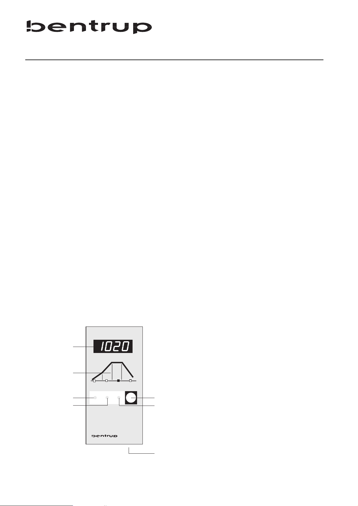
Controller Layout
1 display
2 firing curve with indicators
3 key for selecting the segment of the firing
curve
4 key for increasing the displayed value
5 start/stop key
6 key for decreasing the displayed value
7 mains switch
General Information...........................................1
Security Advice.................................................1
Firing Curves ....................................................1
Typical Firing Curves ............................................2
Entering a Firing Curve .....................................2
Checking the Programme Values ......................3
Further Hints
Reaction on Power Breakdown.........................3
Maximum Values..............................................3
Error Messages .....................................................4
Setting the Parameters..........................................5
Technical Information ..........................................6
THERMOCOMPUTER
1
2
o
3
4
k
o
TC 40
start
stop
5
6
7
Page 3
9
Your brand new bentrup TC40 represents one of the
most popular kiln controllers of the compact class.
The TC40 combines very easy handling, safe and
precise kiln operation at a very reasonable price.
Before operating the TC40, please read and
understand the manual carefully. This familiarizes you
with all functions of the TC40 quickly and ensures
that you can use all the capablities of your control.
Please refer to the security advice of the kiln
manufacturer. Make sure that the control is mounted
at a safe distance from the kiln and that the control is
not exposed to direct heat or radiation when the kiln
is opened whilst it is hot.
The microprocessor controller TC40 provides your
kiln with a precise and reproducable controlling unit.
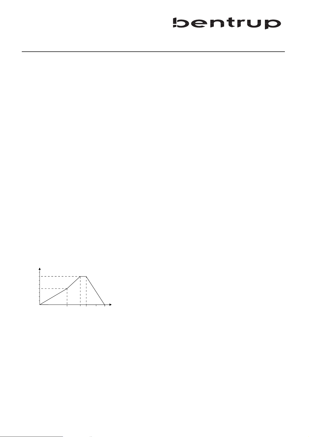
The firing course is shown as a firing curve consisting
of five segments. An example is shown below. This
firing curve consists of the following sements:
a. heating up to 580°C at 120°C per hour
b. heating up to 900°C at maximum power
c. dwell (30 minutes)
d. natural cooling
For easier use, the TC40 has fixed values in the firing
curve:
The rate of heating up can be set to the values 60°C/h,
120°C/h, 240°C, 360°C/h, 480°C/h and maximum
power. The temperature for switching to maximum
power is fixed at 580°C.
The final temperature can be adjusted between 400°C
and 1320°C in 5°C steps. The dwell can be selected 0,
10, 20, 30, 60 minutes.
580
900
[°C]
[min]
(a) (b) (d)(c)
General Information
Security Advice
Firing Curves
Page 4
10
k
Depending on application, clay, glaze etc. it required
very different firing curves. Your dealer will assist you
for detailed questions. Following firing curves are
some typical examples:
Example: The biscuit firing 800°C (refer to table
shown above) is entered as a firing curve as follows:
Power on the controller by the mains switch. After a
few seconds the actual kiln temperature appears on
the display (1).
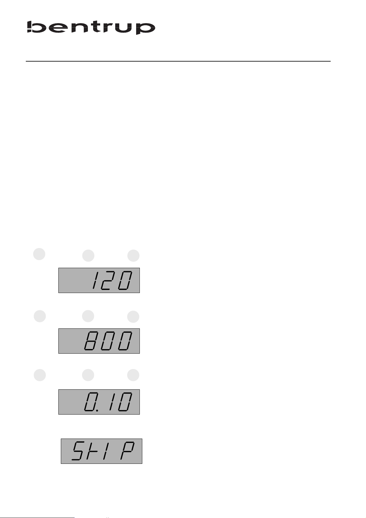
Press the key (3) once. The section (a) of the firing
curve (2) lights up. The display (1) shows the actual
rate for the heat up. Use the keys (4) and (6) to change
this value to 120°C/h (as our example).
Press the key (3) again to select the next segment (b).
Use the keys (4) and (6) to enter the requred final
temperature of the firing (800°C as our example).
If you hold the key (4) or (6) pressed, the displayed
value will run through automatically.
Press the key (3) to step to the next segment of the
curve (section c.). Adjust the dwell to the required
value (e.g. 10 minutes).
Instead of a linear heat up (section a.) you can also
enter an uncontrolled heat up, ie. with maximum
power. This is done by setting the firing curve to SKIP
in the section a. The value SKIP is shown as depicted
left.
Firing heatup(°C/h) final temp. (°C) dwell
biscuit 800°C 120 800 10
biscuit 900°C 120 900 10
glaze 1050°C 240 1050 30
stoneware 1180°C 240 1180 30
stoneware1250°C 240 1250 30
Entering a Firing Curve
Typical Firing Curves
k
o
o
resp.
o
o
resp.
k
o
o
resp.
Page 5

11
If you want to change a value again or you have
skipped a segment unintentionally, use the key (3) to
get back to the beginning of the firing curve. You can
alter all values as often as you like.
To start the firing, press the key (5). The display (1)
shows from now on always the kiln temperature.
Additionally, the firing curve (2) indicates the current
section of the firing.
The flashing decimal point in the right hand corner
indicates programme running.
To check or change the values of a programme when
the firing has already been started, proceed as follows:
Press the key (3), the firing is interrupted automatically
(decimal point stops flashing). Now, you can step
through the segments using the key (3) as described
before. To change a value, use keys (4) and (6). To
continue the firing with the new values press key (5)
again.
For security reasons the firing will be interrupted if a
power breakdown occurs. For special applications a
version with power breakdown restart feature is
available on request.
heat up ..........................60°C to 480°C/h, SKIP
end of heat up................580°C (fix, configurable)
final temperature............400°C to 1320 °C*
dwell..............................0.00 to 1.00 hours
* this value varies depending on the kiln
start
Checking the
Programme Values
Reaction on Power
Breakdown
Maximum Adjustable
Values
stop
Page 6
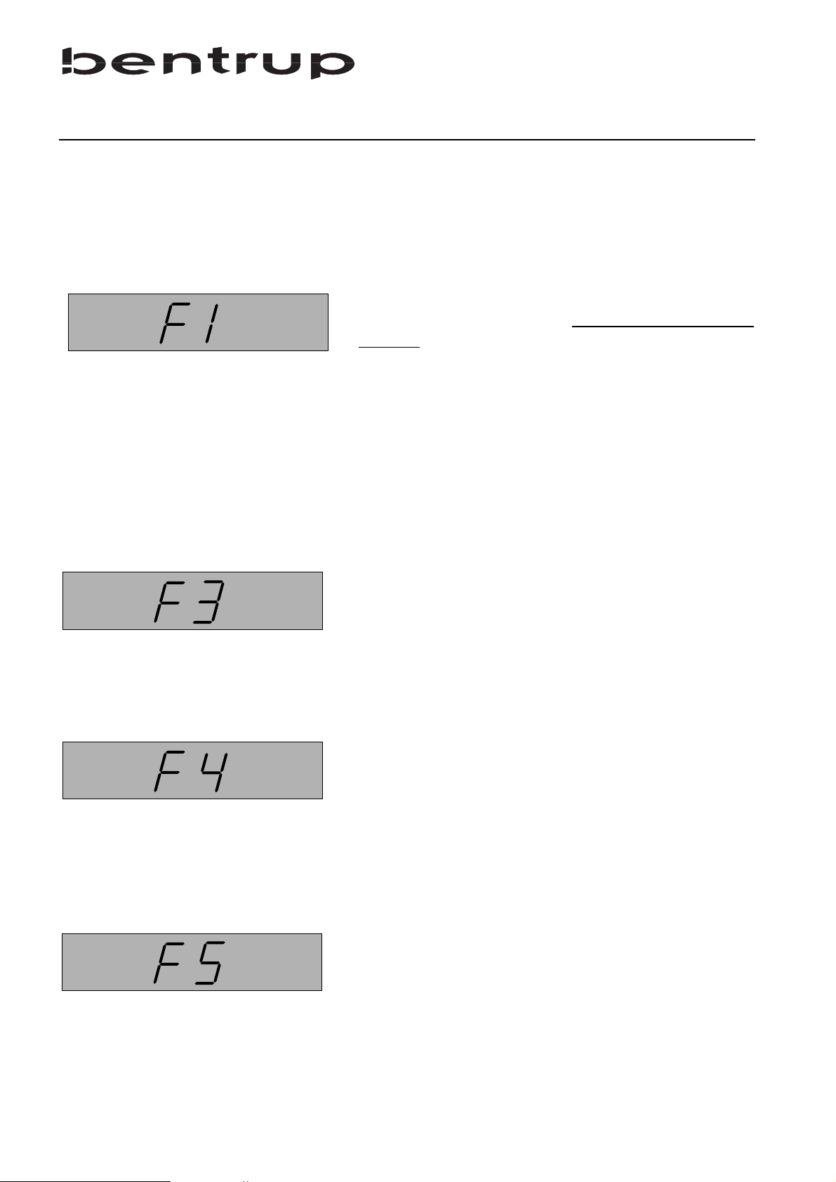
12
The integrated microprocessor inside your TC60
performs continous checking of the firing process. In
case of any malfunction the display will show an error
message pointing to the problem. Following is a
description of the possible error messages:
The kiln doesn´t follow the required temperature
increase. This error message points clearl
y to a kiln
problem. Possible cause:
• broken fuse, power phase or relay failed
• the door (lid) contact is open
• a heating element is broken
• the heating elements are too old
(esp.with high firing temperatures)
• the thermocouple has a short circuit
Thermocouple or thermocouple circuit defect
Possible cause:
• thermocouple broken
• thermocouple wiring bad
• contacts of the connecting plug bad
Impossible values on data acquisition
Possible cause:
• thermocouple polarized bad
• thermocouple temperature less than -15°C
Safety Switch Off features was activated
The TC60 has measured an overtemperature in the
kiln and switched off the kiln by the 2nd power relay
(if fitted). Check carefully the cause before using the
kiln again to avoid further damage ! Ask your dealer
for assistance.
Error Messages
Page 7

Error detected during power-up self check
On every power-up the controller performs a self
check. If an error is detected the controller shows F8
(ROM error) or F9 (hardware error). Please contact
your local dealer.
13
Setting the Parameters of the TC40
This information describes how to adapt the TC40 to the kiln. Usually, this is done by the kiln
manufacturer.
You can call up the parameters to view only; to change them, you need a special
authorization code which is available from us on request.
To get into the parameter menu press the key start/stop and hold it pressed for about 4
seconds. Now, the display reads the first configurable value and you can step through the list
by pressing the key (3).
code usage value range unit
0 type of thermocouple S-R-K-J 0-3 1 max. adjustable temperature 20-1600 °C
2 proportional band 0.0-99.9 %
3 integral time 10-8000 s
4 derivative time 0-999 s
5 cyclus time power relay 1-100 s
6 units for temperatures °C - °F 0-1
-
7 lock error message F1 (heat up check) 0-1
-
8 temp. for switching over to full power 20-1600
°C
Page 8
14
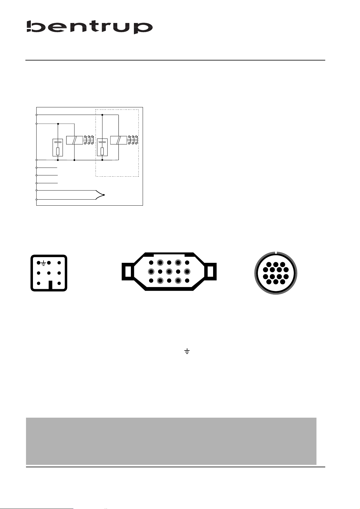
mains supply neurtral
mains supply live
protection ground
(+)
thermocouple
(-)
(optional)
power relay
(heating)
(h,n)
(g)
(f)
(d)
(c)
(b)
(a)
a ... n: electrical links for the controller
(e)*
e.g. 2nd power relay
6
5
4
1
2
3
7
Schematic of a Kiln
Pin Assignment
Technical Informations
HAN 7 D
Important Note
Please compare type of thermocouple used in the kiln with the controllers
thermocouple input marked on the back of the controller. Mismatch can cause
severe damage of kiln and contents
3
1
74
11
8
1412
a
b
c
12
3
45
CPC14HAN 15 D
We reserve the right to make any changes without notice
Operating Instructions TC40 V3.2 (C)opyright 1998 bentrup Industrial Controls, D-35463 Fernwald
connect. function HAN7D HAN15D CPC14
a additional control output (live) 7 C3 12
b control output power relay (live) 6 A3 14
c control output power relays (neutral) 1 B3 13
d protection earth * PE clamp 11
e mains supply live 5 A1 8
f mains supply neutral 2 B1 9
g thermocouple + 3 B5 1
h thermocouple - (type S, R) 4 C5 2
n thermocouple - (type K, J) 4 A5 3
* protection earth should be connected !
 Loading...