

Page 1

178 034 82-3 2018-04-11
Providing sustainable energy solutions worldwide
Installation- and maintenance instruction
BG 550/650/700/800/950
BMS LMV Biogas
J/K
Page 2

Page 3

General
Table of contents
General
GENERAL
1. General Information
_______________________________________________________5
Safety instructions ______________________________________________________5
Actions to take if you smell gas ____________________________________6
Burner servicing schedule ___________________________________________7
Component replacement intervals ________________________________7
Delivery check ____________________________________________________________7
2. Technical data
_______________________________________________________________8
2.1 Burners are intended for use at: _________________________________8
2.2 Dimensions _____________________________________________________________8
2.3 Description BG 550/650 _________________________________________16
2.4 Description BG 700/800/950___________________________________18
3. General instruktions
____________________________________________________20
3.1 General instructions ________________________________________________20
3.2 Operating instructions _____________________________________________20
3.3 Instructions ____________________________________________________________20
3.4 Inspection and maintenance ____________________________________20
3.5 Start up _________________________________________________________________20
3.6 Commissioning of installation___________________________________20
4. Installation
__________________________________________________________________21
4.1 Delivery check _______________________________________________________21
4.2 Preparations for installation _____________________________________21
4.3 Gas supply ____________________________________________________________21
4.4 Electric connection _________________________________________________21
4.5 Skeleton diagrams _________________________________________________22
4.6 Fitting the burner to the boiler __________________________________ 23
4.7 Handling and lifting instruction _________________________________24
4.8 Inspection of gas nozzle before commissioning _________25
5. Setting the burner
_______________________________________________________26
5.1 Setting the combustion assembly ____________________________26
5.2 Setting the air damper ____________________________________________27
5.3 Setting the gas damper __________________________________________27
5.4 Recommended excess air when using default setting 27
5.5 Determining the gas quantity for the system ______________27
5.6 Calculating the quantity of gas supplied ____________________29
6. Service
________________________________________________________________________30
6.1 Servicing the combustion assembly _________________________30
6.2 Servicing air dampers _____________________________________________31
6.3 Replacement of damper motor, air ___________________________ 32
BG700-950 _____________________________________________________________33
BG550/650 _____________________________________________________________33
BG550-950 _____________________________________________________________33
6.4 Replacement of damper motor, gas _________________________ 34
6.5 Flame monitoring and ionisation current check __________35
6.6 Gas nozzle BG 550/650 __________________________________________37
6.7 Gas nozzle BG 550LN ____________________________________________37
6.8 Gas nozzle BG 700/800 __________________________________________38
6.9 Gas nozzle BG 950 ________________________________________________39
6.10 UV detector
___________________________________________________________40
6.11 Setting the air pressure switch _________________________________41
6.12 Setting the min. gas pressure switch ________________________42
6.13 Setting the max. gas pressure switch _______________________43
6.14 Vibration ________________________________________________________________44
7. Handing over of the installation
8. Fault location, functional troubles
9. Regulators
10. Damper motors
__________________________________________________________________46
_______________________________________________________47
___________________________________45
________________________________45
10.1 SQN damper motor ________________________________________________ 47
10.2 SQM damper motor _______________________________________________ 49
11. Gas train
__________________________________________________________________51
11.1 DMK gas butterfly damper ______________________________________ 51
11.2 MULTI-BLOCK VGD40… SKP15/25 ________________________53
11.3 MULTI-BLOCK, MB-DLE 412-420 ___________________________57
12. Electric equipment
___________________________________________________62
12.1 Safety system _______________________________________________________ 62
12.2 Wiring diagram ______________________________________________________63
12.3 Wiring diagram RWF 50:3 _______________________________________ 64
12.4 Wiring diagram RWF 50:2 _______________________________________ 65
12.5 Wiring diagram Jumo 316 _______________________________________ 66
12.7 List of components_________________________________________________ 67
12.6 Components, electrical cabinet ________________________________ 67
13. LMV37 automatic control unit
__________________________________68
13.1 System structure/function description _______________________68
13.2 General information ________________________________________________69
13.3 Technical Data Basic unit LMV37.4... ________________________69
13.4 Connection and internal diagram _____________________________ 74
14. Operation
_______________________________________________________________76
14.1 LMV37 automatic control unit __________________________________ 76
14.2 List of phase displays _____________________________________________ 78
14.3 Automatic control unit levels ____________________________________79
14.4 Setting the automatic control unit _____________________________84
14.5 Backup and restore ______________________________________________ 103
14.6 Fault status message, display of errors and info _______ 107
14.7 Dispaly message of info ________________________________________ 113
14.8 Resetting the automatic control unit _______________________ 114
14.9 Manual output _____________________________________________________115
15. Parameter list
16. Error code list
17. Declaration of conformity
18. General instruction for gasburner
________________________________________________________ 117
________________________________________________________ 126
______________________________________ 140
___________________________ 141
3 Bentone BFG1
Page 4

General
4
Bentone BFG1
Page 5

1. General Information
This Installation and Maintenance manual:
• is to be regarded as part of the burner and must always be kept near
the installation site
• is intended for use by authorised personnel
• must be read prior to installation
• must be observed by all who work with the burner and associated
system components
• work with the burner may only be carried out by certifi ed installers/
personnel
Enertech AB is not liable for any typographical errors and reserves the right
to make design changes without prior notice.
Safety instructions
• The burner may only be used for its intended purpose in accordance
with the product’s technical data.
• The burner may only be installed and operated by authorised
personnel.
• The product is packaged to prevent damage from occurring during
handling. Handle the product with care. Lifting equipment must be
used to lift larger packages.
• The products must be transported/stored on a level surface in a dry
environment, max. 80% relative humidity, no condensation.
Temperature -20 to +60 °C.
• Check that the burner is compatible with the boiler’s output range.
• All components must be installed without being bent, twisted or
subjected to mechanical or thermal forces which can affect the
components.
• The burner must be installed so that it complies with local regulations
for fi re safety, electrical safety, and fuel distribution.
• The gas outlet from the pressure regulator shall be confi gured in
accordance with applicable regulations and lead to a safe area.
• Make sure when installing the equipment that there is enough space to
service the burner.
• Permitted temperature during operation -10 to +60 °C. Max 80%
relative humidity, no condensation.
• The installer must ensure that the room has adequate air supply.
• The room must comply with local regulations pertaining to its intended
use.
• The installation site must be free of chemicals.
• Burner pipes, fan wheels and air dampers may contain sharp edges.
• The surface temperature of the burner’s components can exceed 60
°C.
• Caution: The burner has moving parts, and there is risk of crushing
injuries.
General
172 515 01 2018-01-02
5 Bentone
Page 6

General
• The electrical installation must be professionally carried out in
accordance with applicable high voltage regulations, as per Enertech’s
recommendations.
• Before servicing, shut off the fuel supply and turn off the power to the
burner.
• Seal inspections must be performed during installation and servicing to
prevent gas leakage.
• Care should be taken by the installer to ensure that no electrical cables
or fuel lines are crushed or otherwise damaged during installation or
servicing.
• If the boiler is equipped with an access hatch, this must be equipped
with a hatch opening switch connected to the burner's safety system.
• When in operation, the burner’s noise level can exceed 85 dBA.
Use hearing protection.
• The burner must not be put into operation without proper safety and
protection devices.
• A Class BE fi re extinguisher is recommended.
• It is forbidden to alter thedesign or use accessories which have not
been approved by Enertech in writing.
• Prior to operation, the following points must be checked:
- fi tting and installation work has been completed and approved
- electrical installation has been correctly performed
- fl ue gas ducts and combustion air ducts are not blocked
- all actuators and control and safety devices are in working order and
correctly set
Actions to take if you smell gas
Turn off the equipment and the boiler. Open windows and doors. Prevent
open fl ames or sparking, e.g. do not turn lights on or off, do not use any
electrical appliances, do not use mobile phones. Open windows and doors.
Close the gas ball valve. Warn residents; do not use doorbells. Evacuate
the building. Notify the installer or gas supplier once the building has been
evacuated.
172 515 01 2018-01-02
Bentone
6
Page 7

General
Burner servicing schedule
Servicing must be carried out once a year or after 3000 hours of operation
Burner 1 year 3000 hrs
Inspection of electrical installation 1 year 3000 hrs
Leakage check 1 year 3000 hrs
Filter 1 year replacement at ∆p>10 mbar 3000 hrs replacement at ∆p>10
mbar
Electrodes Replacement/Cleaning 1 year Replacement/Cleaning 3000 hrs
Brake disc Replacement/Cleaning 1 year Replacement/Cleaning 3000 hrs
Motor 1 year 3000 hrs
Fan wheel 1 Year
Replacement when cleaning
needed/ imbalance
3000 h
Replacement when cleaning
needed/ imbalance
Component replacement intervals
Control system 10 years 250,000 starts
Valve control system 10 years 250,000 starts
Pressure switch 10 years 250,000 starts
Ignition system with flame guard 10 years 250,000 starts
UV flame sensor 10000 hrs N/A
Gas pressure regulators 15 years N/A
Gas valve without seal testing 10 years 250,000 starts
Gas valve with seal testing Replacement upon fault detection N/A
Gas pressure switch 10 years 250,000 starts
Safety blow-off system 10 years N/A
Damper motor N/A 500,000 starts
Contactor 10 years 500,000 starts
The burner and its components must be recycled according to applicable regulations.
Delivery check
• Make sure everything is delivered and the goods have not been
damaged during transit.
• If something is wrong with a delivery, report it to the supplier.
• Transport damage must be reported to the shipping company.
7 Bentone
Page 8

General
2. Technical data
2.1 Burners are intended for use at:
• Water heating generators
• Steam generators
• Industrial applications
• Hot air generators
2.2 Dimensions
C
B
E
G
F
E
I
H
Dimensions stated in mm
Type
Standard 1 256 226
BG 550
Standard 3 456 426
BG 650
BG 700
BG 800
Standard 1 316 286
Standard 2 416 386
Standard 363 328
Långt utförande 663 628
Standard 396 361
Långt utförande 696 661
Length of
burner tube
A
Flange
measure A
D
**J
Burner tube
measure B
162 162Standard 2 356 326
184 162
220 205
261 205
Burner tube
measure C
8
BG 950
Bentone BFG1
Standard 1 350 310 280 254
Page 9

D E F G H I **J
BG 550
BG 650
BG 700
BG 800
BG 950
660 320 400 *590 *743 343 200
660 320 400 *590 *743 343 200
820 410 510 *730 *970 420 200
820 410 510 *730 *1022 472 200
890 410 510 *730 *1027 472 200
* The above dimensions are max. measurements. Depending on the
components used, the measurements may vary.
** Min. recommended distance to floor.
2.2.1 Heat generator connection dimensions
General
BG 550
BG 650
BG 700
BG 800
BG 950
K L M
M12 (Ø 210) Ø 255-290 Ø 170
M12 (Ø 210) Ø 254-280 Ø 190
M14 (Ø 280) Ø320-380 (Ø 210) Ø 230
M14 (Ø 280) Ø320-380 (Ø 210) Ø 270
M14 (Ø 340) Ø420-490 (Ø 260) Ø 290
M
K
L
9 Bentone
Page 10

General
2.2.2 Capacity range
Type Grade
of gas
BG 550 G20
BG 550 G25
BG 550 G30
BG 550 G31
BG 650 G20
BG 650 G25
BG 650 G30
BG 650 G31
BG 700 G20
BG 700 G25
BG 700 G31
BG 800 G20
BG 800 G25
BG 800 G30
BG 950 G20
BG 950 G25
BG 950 G30
BG 950 G31
Capacity kWGas quantity
at min. power
Nm3/h 1)
140–628 15 67
140–628 17 73 see data plate
140–628 4 19 see data plate
Gas quantity
at max.
power Nm3/h
1
)
Max.
connection
pressure
mbar
360
Min
connection
pressure mbar
see data plate
140–628 6 25 see data plate
200–1125 21 118
200–1125 24 137 see data plate
200–1125 6 35 see data plate
360
see data plate
200–1125 6 35 see data plate
300–1500 31 157
360–1500 37 183 see data plate
360
see data plate
380–1650 15 67 see data plate
380–2400 40 252
380–2400 46 293 see data plate
360
see data plate
380–2400 40 252 see data plate
500–3200 52 336
500–2800 61 342 see data plate
500–3200 15 98 see data plate
360
see data plate
500–3200 20 130 see data plate
Lower heat value Hu at normal state 15°C and 1013.25 mbar EN676
Grade of gas
Natural gas
Natural gas
Propane
Butane
kWh/Nm
3
G20 9.5 34.02 8126
G25 8.2 29.25 6986
G31 24.6 88.00 21019
G30 32.5 116.09 27728
MJ/Nm
3
kcal/Nm
3
Gas quantity and capacity vary according to grade of gas and connection
pressure.
10
Bentone
Page 11

, RO, SE,
3R
2.2.3 Appliance categories
Only dry gas is permitted for use
BG 550
General
Gerätekategorien
Appliance categories
II
2R/3R
II
2H3B/P
II
2H3P
II
2L3B/P
II
2E3B/P
I
2E(R)B
I
3P
BG 650
Gerätekategorien
Appliance categories
II
2R/3R
II
2H3B/P
II
2H3P
II
2L3B/P
II
2E3B/P
I
2E(R)B
I
3P
BG 800
Gerätekategorien
Appliance categories
II
2R/3R
II
2H3B/P
II
2H3P
II
2L3B/P
II
2E3B/P
I
2E(R)B
I
2H
I
3B/P
I
Versorgungsdrücke
Supply pressures
Bestimmungsländer
Countries of destination
30-360mBar "BG, CZ, DE, EE, ES, FR, GR,
HU, IS, IT, LU, LV, NO, PT, SI,
All countries"
30-360mBar AT, CH, CY, DK, FI, LT, RO, SE,
SK
30-360mBar GB, IE,
30-360mBar NL, RO
30-360mBar PL
30-360mBar BE
30-360mBar BE
Versorgungsdrücke
Supply pressures
Bestimmungsländer
Countries of destination
40-360mBar "BG, CZ, DE, EE, ES, FR, GR,
HU, IS, IT, LU, LV, NO, PT, SI,
All countries"
40-360mBar AT, CH, CY, DK, FI, LT
SK
40-360mBar GB, IE,
40-360mBar NL, RO
40-360mBar PL
40-360mBar BE
40-360mBar BE
Versorgungsdrücke
Supply pressures
40-360mBar ”CZ, DE, EE, ES, FR, GR, IT,
40-360mBar ”AT, CH, CY, DK, FI, LT, RO,
40-360mBar GB, IE,
40-360mBar NL, RO
40-360mBar PL, RO
40-360mBar BE
40-360mBar HU, LT, LV
30-360mBar BE, HU,LT
30-360mBar GB,LT
Bestimmungsländer
Countries of destination
LT, LU, LV, IT, NO, PT, SI,
All countries”
SE,
SK”
11 Bentone
Page 12

General
Bestimmungsländer
Countries of destination
NO,
,
3R
BG 700
Gerätekategorien
Appliance categories
Versorgungsdrücke
Supply pressures
II
2R/3R
II
2H3P
II
2H3P
II
2L3P
II
2E3P
I
2E®
I
3P
BG 950
Gerätekategorien
Appliance categories
II
2R/3R
II
2H3B/P
II
2H3P
II
2L3B/P
II
2E3B/P
I
2E(R)B
I
2H
I
3B/P
I
40-360mBar ”BG, CZ, DE, EE, ES,
HU, IS, IT, LU, LV,
All countries”
40-360mBar ”AT, CH, CY, DK, FI, LT
SK”
40-360mBar GB, IE,
40-360mBar NL, RO
40-360mBar PL
40-360mBar BE
40-360mBar BE
Versorgungsdrücke
Supply pressures
40-360mBar ”CZ, DE, EE, ES, FR, GR, IT,
40-360mBar ”AT, CH, CY, DK, FI, LT, RO,
40-360mBar GB, IE,
40-360mBar NL, RO
40-360mBar PL, RO
40-360mBar BE
40-360mBar HU, LT, LV
30-360mBar BE, HU,LT
30-360mBar GB,LT
Bestimmungsländer
Countries of destination
LT, LU, LV, IT, NO, PT, SI,
All countries”
SE,
SK”
Bentone
12
Page 13

General
2.2.4 Electric Specification
Burner correspond to IP40
Type BG 550 BG 650
Motor
230/400V, 50Hz,
3,5/2,5A, 0,75kW
2860 Rpm
The recommended main fuse
motor
Control power
Sound
Type BG 700 BG 800 BG 950
Motor
89 dBA ± 0,5 dBA 91 dBA ± 0,5 dBA
230/400V, 50Hz,
230V1F~2,5A
10,4/5,5A, 3,0kW,
2940 Rpm
The recommended main fuse
motor
C16A D20A D20A
230/400V, 50Hz,
6,5/4,0A, 1,5kW,
2890 Rpm
C10A
230/400V, 50Hz,
20,5/12,0A,
5,5kW, 2950 Rpm
230/400V, 50Hz,
21,5/13,5A,
5,5kW, 2950 Rpm
Control power
Sound
93 dBA ± 0,5 dBA 96 dBA ± 0,5 dBA 97 dBA ± 0,5 dBA
Measurements according to EN 3746: 2010
Alt.1 The sound level of the burner can be reduced by equipping the burner
with silencer. Installation must be done so it does not prevent air supply
to the burner.
Alt.2 The burner’s noise level can be reduced by connecting the burner’s air
intake to the air duct that opens into an appropriate location. Installation
must be done so it does not prevent air supply to the burner.
230V1F~2,5A
13 Bentone
Page 14

General
2.2.5 Working field
BG 550
140-628 kW
Do not exceed working
field
!
BG 650
200-1125 kW
Do not exceed working
field
!
14
12
10
8
6
4
2
0
Pressure in fire place mbar
-2
100 200 300 400 500 600 700
14
12
10
8
6
4
2
0
-2
200 300 400 500 600 700 800
Pressure in fire place mbar
900 1000 1100 1200
kW
kW
14
Bentone
Page 15

General
mbar
BG 700
G20, G21 300-1500 kW
G31 380-1650
Do not exceed working
field
!
BG 800
380-2400 kW
Do not exceed working
field
!
14
12
10
8
6
4
2
0
-2
200 400 600 800 1000 1200 1400 1600
32
28
24
20
16
12
8
4
0
-4
200 400 600 800 1000 1200 1400 1600 1800 2000 2200 2400
kW
kW
BG 950
500-3200 kW
Do not exceed working
field
!
32
28
24
20
16
12
8
4
0
-4
400 900 1400 1900 2400 2900 3400
kW
15 Bentone
Page 16

General
2.3 Description BG 550/650
11
10
12
13
14
122
2
3
4
5
6
7
15
89
12
16
11
17
18
16
Bentone
Page 17

General
17
16
19
22 21
2
4
9
2.3.1 Components BG 550/650
1. Burner tube
2. Damper motor, gas
3. Min. gas pressure switch/tightness check
4. MultiBloc
5. Air damper
6. Damper motor, air
7. Connection gas fi ttings
8. Air pressure switch
9. Fan house
10. Sight glass
11. AZL display for LMV automatic control unit
12. Switch 0-l
13. Brake plate adjustment
20
14. Guide bar
15. Ignition electrode
16. Shrouded disc
17. Ionisation electrode
18. Electrical connection
19. Gas nozzle
20. Motor
21. Measuring nipple, fan pressure
22. Connection fl ange
18
17 Bentone
Page 18

General
2.4 Description BG 700/800/950
14
5
1
2
3
4
7
10
15
6
8
9
12
16
17
11
18
18
Bentone
Page 19

17
General
22
21
19
2.4.1 Components BG 700/800/950
1. Burner tube
2. Damper motor, gas
3. Min. gas pressure switch/tightness check
4. MultiBloc
5. Air damper
6. Damper motor, air
7. Connection gas fittings
8. Air pressure switch
9. Fan house
10. Sight glass
11. AZL display for LMV automatic control unit
12. Switch 0-l
13.
18
20
14. Guide bar
15. Ignition electrode
16. Shrouded disc
17. Ionisation electrode
18. Electrical connection
19. Gas nozzle
20. Motor
21. Measuring nipple, fan pressure
22. Connection flange
19 Bentone
Page 20

General
3. General instruktions
3.1 General instructions
The installation of the gas burner must be carried out in accordance with
current regulations and standards. The installers of gas burners should
therefore be acquainted with all regulations and ensure that the installation
complies with the requirements. The installation, mounting and adjustment
should be made with the greatest care and only the correct gas should be
used.
3.2 Operating instructions
The operating instructions accompanying the burner should be left in a
prominent position in the boiler room.
3.3 Instructions
The user should be thoroughly in-structed in the function of the gas burner
and the whole installation. The supplier must instruct the user.
3.4 Inspection and maintenance
Daily inspection is advisable..
3.5 Start up
After the burner has been fitted to the boiler and the electric connection, the
leakage control, the venting and the electric function test have been carried
out, the burner will be ready for start-up.
Howerer, study the sections dealing with adjustments of multi-bloc,
combustion air and combustion head. Open the ball valve and switch on the
main switch. If the burner starts the actual adjustment can be made.
3.6 Commissioning of installation
Control of the combustion. The combustion quality is checked by means of a
flue gas analysis device. Adjust the burner to appr. 20%
excess air in accordance with the table. Check the flue gas temperature.
Calculate the efficiency. Check also the actual gas volume on the gas meter
so that the correct input is achieved.
20
Bentone
Page 21

4. Installation
4.1 Delivery check
Check that all has been delivered and that the goods have not been
damaged during transport. If that is not the case, please notify the delivery
company. Transport damages should be reported to the forwarding agency.
4.2 Preparations for installation
Check that the measurements and capacity range of the burner are
compatible with the boiler. The power ratings on the type plate refer to the
min. and max. power of the burner.
4.3 Gas supply
For good operating safety, it is important that the gas supply system is
installed correctly.
Consider the following:
1. Check that the burner is approved for the gas quality of the installation.
If not, please contact the supplier.
2. Check that the gas components of the burner are approved for
indicated gas pressure.
3. The gas supply system should be installed in accordance with current
standards.
4. Pipe lines should be run so that service on boiler and burner is
facilitated.
5. Pipe lines should be run so that eventual contaminants cannot come
into contact with the gas components.
General
4.4 Electric connection
Before starting the electric installation, the main switch must be turned off.
If the boiler has a 7-pole and a 4-pole Eurostecker connector, these usually
fit directly to the burner. If not, use the connectors included.
(Refer to connection under Electric equipment)
If an electric connection other than the one recommended by Enertech is used, a risk of damage and
injury can arise.
!
21 Bentone
Page 22

General
4.5 Skeleton diagrams
4
5a
2
1
3
5b
6a
8910
6b
Multibloc
1. Ball valve
2. Filter
3. Governor
4. Pressure gauge with shut-off cock
5a. Gas pressure switch, mini
5b. Gas pressure switch, maxi
6a. Main valve, 2 -stage
6b. Safety valve
7. 1) Valve proving system
8. Air damper motor
9. Air pressure switch
7
10. Gas burner control LMV
Pos. 5b, 7: Components not required according to EN 676.
1)
Required over 1200 kW according to EN 676
When Bio gas is used, Enertech shall always be contacted.
!
Bentone
22
Page 23

4.6 Fitting the burner to the boiler
Use 4 x M12 bolts to fit the burner to the boiler. See technical data for the
hole pattern.
To make the fitting process easier, it is possible
to separate the burner body from the gas flange
with the combustion head and valve assembly
in place.
Proceed as follows:
1. Ensure that no power is going to the
burner. Switch off the main power supply
and disconnect the Euro plugs from the
burner. NOTE! If the burner is directly
connected, ensure that all components
on the burner are without power.
2. Remove the cover plate from the fan
housing.
3. Undo the nut (D) to the nozzle assembly.
(applies to BG 550 & 650; does not feature on BG 700, 800 & 950)
4. Disconnect the electrical cables to the valve assembly and gas damper
motor.
5. Undo the screws (B) on both sides.
6. Undo the end stops (C) on the guides.
7. Disconnect the ignition cable, ionisation cable and control arm
(550/650 only) from the gas nozzle.
8. Pull out the burner body from the guides and put it in a suitable place.
After separating the burner body and gas flange it is easier to fit the gas
flange with the combustion head and valve assembly to the boiler. Once the
gas flange is fitted to the boiler, it is easy to lift the burner body up onto the
guides. Assemble the burner in reverse order to its disassembly.
General
Service position
Check the gas tightness.
!
23 Bentone
Page 24

General
4.7 Handling and lifting instruction
4.7.1 BG 550, BG 650
Option
The lifting aid we used
here are available as
!
spare parts, Figure 1
4.7.2 BG 700, BG 800, BG 950
Figure 1
3
24
1
2
Bentone
Page 25

4.8 Inspection of gas nozzle before
commissioning
The gas nozzle can easily be inspected by using the guides on the burner.
Proceed as follows:
1. Ensure that no power is going to the burner. Switch off the main power
supply and disconnect the Euro plugs from the burner.
If the burner is directly connected, ensure that all components on
the burner are without power.
!
2. Remove the cover plate from the fan housing.
3. Undo the nut (D) to the nozzle assembly. (applies to BG 550 & 650;
does not feature on BG 700, 800 & 950)
4. Disconnect the ignition cable and ionisation cable for the gas nozzle.
5. Ensure there is enough slack in the electrical cables to the valve
assembly and gas damper motor to pull out the burner body in the rear
position on the guides. If there is not enough slack the cables can be
disconnected.
6. Undo the screw (B) on both sides.
7. Pull out the burner on the guides.
8. Undo the screw(s) (A) on the gas flange.
9. Take out the gas nozzle.
10. See section 11.7-11-10
Re-assemble the burner in reverse order to that described above. When reassembling, make sure that the O-ring located between the gas nozzle and
the gas flange is in the correct position when the nozzle is re-fitted.
General
If the burner tube is the long variant, the gas nozzle must be removed from the connection tube and then
inserted backwards into the fan housing (from the boiler) to enable maintenance of the brake plate, nozzle,
!
electrodes, etc.
25 Bentone
Page 26

General
5. Setting the burner
5.1 Setting the combustion assembly
It may sometimes be necessary to adjust the combustion assembly, i.e. the
position of the brake plate in the burner tube.
5.1.1 Setting the combustion assembly, BG
550 & 650
The burner is equipped with a lever that changes the position
of the brake plate in the combustion head. This is used to set
the correct pressure drop across the combustion assembly and
thereby obtain good combustion without ripples.
The best position is, among other things, dependent on the input
power and overpressure in the boiler.
A general rule of thumb is that the smaller the capacity, the smaller the gap
should be between the brake plate and the combustion assembly.
The position of the brake plate also has an impact on the quantity of air
supplied for combustion. This means that once the brake plate has been
adjusted, the combustion should be checked and, if necessary, the setting of
the air damper adjusted to obtain good combustion.
Make the adjustment by turning screw X.
A left turn opens the brake plate, providing a lower pressure drop and more
air to the combustion process.
A right turn closes the brake plate, providing a higher pressure drop and less
air to the combustion process.
5.1.2 Setting the combustion assembly, BG 700,
800 & 950
The burner is not equipped with a lever that changes the position of the
brake plate in the combustion head.
On these burners the combustion assembly is designed so that good
combustion can be obtained without adjusting the brake plate.
X
5.2 Setting the air damper
The position of the air damper must be adjusted to achieve a suitable fuel-air
mixture in the operational events that are programmed.
See section 13.4 (LMV) for the setting procedure.
Bentone
26
Page 27

5.4 Calculate prepurge time
Parameter 225 is used to set the blowing time
General
V = Fire box size m
3
Q = Burner output at prepurge [kW]
X = Prepurge time seconds Water boilers
100% air rate
50 % air rate
33% air rate
at least 20s prepurge time
at least 40s prepurge time
at least 60s prepurge time
X = Prepurge time seconds Steam generators
at last prepurge 5 times fi rebox volume
X = Prepurge time seconds Industrial heating process
at least prepurge at least 5 times fi rebox and
adapted compartments volumes together
Local regulations must be followed
Calculation example:
Example A: V=2m
Example B: V=9,5m
Example C: V=25m
3
3
3
Q=200
Q=500
Q=2200
Example A
Example B
Example C
X = V
((Q · 1,2) / 3600) ((200 · 1,2)/3600)
X = V
((Q · 1,2) / 3600) ((500 · 1,2)/3600)
X =
((Q · 1,2) / 3600) ((2200 · 1,2)/3600)
.
5
.
5
.
5
V
=
=
=
2 · 5
9,5 · 5
25 · 5
= 150 seconds
= 285 seconds
= 170 seconds
5.3 Setting the gas damper
The position of the gas damper must be adjusted to achieve the desired
minimum and maximum input power.
See section 13.4 (LMV) for the setting procedure.
27 Bentone
Page 28

General
5.4.1 Example of how to calculate the gas quantity
(natural gas G20):
V0 = Desired quantity of gas [Nm3/h]
Q = Boiler output [kW]
= Gas heat value [kWh/Nm3] or [MJ/Nm3] or [kcal/
H
U
Nm3]
η=
Calculation example:
Q = 2200 kW
Boiler efficiency [%]
H
= Example A: 34,020 MJ/Nm
U
3
Example B: 9.5 kWh/Nm3
Example C: 8126 kcal/Nm
3
η = 90%
Example A
V
0A
Example B
V
0B
Example C
V
0C
If the barometer reading (altitude), pressure and temperature of the gas
deviate significantly from normal values, this must be taken into account as
follows:
T = Temperature of gas at the gas meter [°C]
B = Barometer reading [mbar]
P = Pressure of gas at the gas meter [mbar]
f = Factor calculated for multiplication with flow in Nm
V = Actual flow [m
f =
= Q . 3600
· η
H
u
= Q
· η
H
u
=
Q
· 0,00116 · η
H
u
arrive at actual flow in Nm
273
273+T 1013.25
B+P
·
=
≈
=
3
/h.
2200 · 3600
34,200 · 0.90
2200
9.5 · 0.90
2200
8126 · 0.00116 · 0.90
3
/h to
≈ 258 Nm
≈ 257 Nm
≈ 259 Nm3/h
3
/h]
3
/h
3
/h
28
Bentone
Page 29

Calculation example:
T = 15°C
B = 945 mbar
P = 15 mbar
General
f = 273
273+15 1013.25
.
945+15
≈ 0.90 Nm
3
/h
This means that the quantity of gas read from the gas meter should actually
be read off as 1.11 . the calculated flow in a normal state.
V = V
= V
V
A
V
=
B
V
=
C
. f
0
. f = 258 . 0.90 ≈ 232 m3/h
0A
V
. f = 257 . 0.90 ≈ 231 m3/h
0B
V
. f = 259 . 0.90 ≈ 233 m3/h
0C
5.5 Calculating the quantity of gas
supplied
The quantity of gas supplied can be calculated if the system is equipped with
a gas flow meter of some type. The procedure here is usually to measure
how long it takes for the burner to consume a certain quantity of gas.
To measure:
t = Time for a certain quantity of gas consumed by the burner. [h]
M = Quantity of gas consumed. [m
3
]
V = Actual gas flow [m
V = M
t
[m
3
/h]
Calculation example:
t = 1 min 10 s
M = 4500 dm
M = 4500 = 4.5 m
3
(litre)
3
1000
t = 1 + 10 = 0.0194 h
60 3600
3
V = M = 4.5 ≈ 232 m
/h
t 0.0194
3
/h]
29 Bentone
Page 30

General
6. Service
Whoever carries out service and maintenance on the burner must be
authorised to do so. If components need to be replaced, the replacements
must be of the same make and type and be approved by the authorities. If
the burner is to be used for a different grade of gas, a new adjustment must
be carried out. If town gas is to be used, it is also necessary to convert the
combustion assembly; in some cases the multi-block or valves and gas train
may also need to be changed to a larger type.
6.1 Servicing the combustion assembly
Removal and installation
1. Switch off the main power supply and disconnect the Euro plugs from
the burner.
If the burner is directly connected, ensure that all components on
the burner are without power.
!
2. Remove the cover and disconnect the ignition cable, ionisation cable
and control arm (550/650 only) from the gas nozzle.
3. Loosen the nuts (B) and pull the burner body out of the guides.
4. Loosen the screw (A); this releases the combustion assembly and
allows it to be lifted out.
5. Check and clean the brake plate and gas inlet. If necessary, replace
the worn parts.
6. Check the ignition electrode (see chapter 11.7–11.10). Replace if
necessary.
7. Check the ionisation electrode (see chapter 11.7–11.10). Replace if
necessary.
8. Fit the combustion assembly in reverse order.
9. Press the burner together and lock using the nuts (B).
10. Fit the Euro plugs and turn on the main power supply.
11. Check/adjust the combustion.
30
Bentone
Page 31

6.2 Servicing air dampers
Removal and installation
1. Switch off the main power supply and disconnect the Euro plugs from
the burner.
If the burner is directly connected, ensure that all components on
the burner are without power.
!
2. Loosen the nuts (B) and pull the burner body out of the guides.
3. Remove the intake grille at the air intake.
4. Remove the screws (G) securing the damper motor mounting plate.
5. Lift up the damper motor.
6. Clean the air damper (F) and the intake. Lubricate any damper shaft.
7. Re-install the damper motor and mounting plate on the air intake.
Ensure that the damper shaft and control arm are connected correctly.
8. Adjust the home position of the damper before tightening the screws
(I).
9. Push the damper motor forwards and backwards in the adjustment
slot.
10. Lock the damper motor in position where the damper is almost
engaged but still has a small air gap by the fan housing.
11. Install the intake grille for the air intake.
12. Press the burner together and lock using the nuts (B).
13. Check/adjust the combustion.
General
31 Bentone
Page 32

General
6.3 Replacement of damper motor, air
Removal and installation
1. Switch off the main power supply and disconnect the Euro plugs from
the burner.
If the burner is directly connected, ensure that all components on
the burner are without power.
!
2. Disconnect the damper motor cable from the automatic control unit.
3. Remove the screws (I) securing the damper motor.
4. Loosen the screws (G) to the damper motor mounting plate.
5. Lift up the damper motor.
6. Remove (H) the control arm from the motor shaft.
7. Remove the damper motor from the mounting plate (I).
SQM must be connected and supplied with power before
installation to ensure that the motor shaft and direction of rotation
!
are set correctly.
8. Install the new damper motor on the mounting plate.
For BG 550/650, SQN 14 is used for air control.
For BG700/800/950, SQM 33 is used.
!
Parameter 601.00:0
Parameter 601.01:1
Parameter 602.00:0
Parameter 602.01:1
9. Fit the control arm on the damper motor shaft. It is important that the
screw is perpendicular to the plane of the shaft.
10. Re-install the damper motor and mounting plate on the air intake.
Ensure that the damper shaft and control arm are connected correctly.
11. Connect the damper motor cable to the automatic control unit.
12. Fit the Euro plugs and turn on the main power supply.
13. Adjust the home position of the damper before tightening the screws.
14. Push the damper motor forwards and backwards in the adjustment
slot.
15. Lock the damper motor in position where the damper is almost
engaged but still has a small air gap by the fan housing.
16. Connect the damper motor cable to the automatic control unit.
17. Fit the Euro plugs and turn on the main power supply.
18. Check/adjust the combustion.
32
!
Bentone
NOTE! When resetting dampers, ensure that they do not
engage in the close damper position. If dampers do engage, the
automatic control unit will report an error message.
Page 33

General
BG700-950
BG550/650
G
I
G
G
I
I
G
BG550-950
I
H
33 Bentone
Page 34

General
6.4 Replacement of damper motor, gas
Removal and installation
1. Switch off the main power supply and disconnect the Euro plugs from
the burner.
If the burner is directly connected, ensure that all components on
the burner are without power.
!
2. Disconnect the damper motor cable from the automatic control unit.
3. Undo the screw (Y) on the connection between the motor and damper.
4. Undo the screws (X) and remove the damper motor from its damper
plate.
5. Install the new damper motor, tighten the screws (X).
An SQN 13 damper motor must be used to adjust the gas valve.
!
6. When tightening screw (Y), ensure that the damper is in the closed
position.
7. Connect the damper motor cable to the automatic control unit.
8. Fit the Euro plugs and turn on the mains power.
9. Check / adjust combustion.
34
Bentone
Page 35

6.5 Flame monitoring and ionisation
current check
The standard version of the burner is monitored according to the ionisation
principle. The ionisation current should be checked on initial start-up and at
each service visit.
The reason for low ionisation current can be leakage current, poor
connection to earth, fouling or incorrectly positioned ionisation electrode in
the combustion head. Sometimes the wrong gas-air mixture can also cause
a very poor ionisation current.
The ionisation current is measured with a microampere meter (µA) that is
connected in series with the ionisation electrode and the gas burner control.
Connect the µA meter according to the figure. The minimum required
ionisation current is shown in the table. In practice, this current must be
significantly higher, preferably more than 10µA. The connection of the µA
instrument is made easier by the fact that all gas burners are equipped with
a divisible ionisation cable.
General
Technical data
For continuous operation!
No-load voltage at ION terminal
(X10–05 terminal 2)
Protect the ionization probe against electric shock hazard!
Approx. UMains
!
Short-circuit current Max. AC 1 mA
Required detector current Min. DC 4 µA, flame display approx.
30%
Possible detector current Max. DC 16…40 µA, flame display
approx. 100%
Threshold values when flame is supervised by an ionization probe:
- Start prevention (extraneous
light)
- Operation Intensity of flame (parameter 954) >24%
Intensity of flame (parameter 954) ≥18%
35 Bentone
Page 36

General
ION input
Ionization current in
A
Flame intensity in %
7541d46e/0208
ION input
100
90
80
70
60
50
40
30
20
10
Flame intensity in %
0
0 2 4 6 8 10 12 14 16 18 20
Ionization current in µ A
µ
Figure 1: Ionization input at AC 120 V / AC 230 V
LMV
X10-05,2
Bentone
36
Page 37

6.6 Gas nozzle BG 550/650
General
Towngas
Biogas (UV detector)
Natural gas, Propane
6.7 Gas nozzle BG 550LN
A = 10 mm Front edge of brake plate
B = 3 mm
A
B
A = Position of ionisation detector
B = Position of ignition electrode
A B
37 Bentone
Page 38

General
6.8 Gas nozzle BG 700/800
Natural gas, Propane
3-4
≈
1
Propane
45°
Natural gas
15-20
Biogas (UV detector)
10-12
3-3,5
38
Bentone
Page 39

6.9 Gas nozzle BG 950
Natural gas, LPG
Distance electrode - brake plate.
3-4
45°
General
Biogas (UV-sond)
39 Bentone
Page 40

General
6.10 UV detector
This should not be exposed to temperatures higher than 60°C. The current
passing though the UV detector, when it is lit up, should be at least 70 µA for
LFL1. This current can be measured using a multimeter, although this is only
necessary if a malfunction is suspected.
If flame detectors QRA2… / QRA4.U / QRA10... are used for
flame supervision with the LMV37.4..., it must be ensured that the
!
basic unit is permanently connected to power (conforming to EN
230 / EN 298), thus enabling the system to detect flame detector
failures during startup and shutdown.
Operating voltage Max. 350 V peak
Required detector current in
operation
Possible detector current in
operation
Permissible length of flame
detector cable
- normal cable (laid separately)
Min. 70 µA
Max. 600 µA
Max. 20 m
UV flame detector QRA...Measuring circuit for detector
current measurement
Legend
A Incidence of light
C Electrolytic capacitor 100...470 µF;
DC 10...25 V
M Microammeter Ri max. 5000
• Input QRA... is not short-circuit-proof! Short-circuits of X1006 Pin 2 against earth can destroy the QRA... input
!
Threshold values when flame is supervised by QRA...:
• Simultaneous operation of QRA... and ionization probe is
not permitted!
- Start prevention (extraneous light) Intensity of flame (parameter 954) ≥18%
- Operation Intensity of flame (parameter 954) >24%
A
QRA
+
-
M
C
+
X10-06.2
X10-06.1
LMV
-
!
Warning!
40
Bentone
Page 41

6.11 Setting the air pressure switch
The air pressure switch should block the burner if the air quantity supplied
for combustion is insufficient. The air pressure switch must be set so that,
if there is a defective air supply at the burner’s max. or min. capacity, it
reacts before the monitored pressure falls so much that it results in poor
combustion.
Inställningsområde ca:
LGW 10 1-10 mbar
LGW 50 2,5-50 mbar
Setting for air pressure switch
1. Remove the protective cover, screw (Y).
Be careful when adjusting the air pressure switch; it contains a
live component.
!
General
2. Start the burner.
3. Carefully turn the scale on the air pressure switch clockwise until the air
pressure switch stops the burner. Is the tolerance on the scale for
the min. air pressure switch approx. ±15%?
4. Try to find the pressure at which the burner stops for both the
minimum and maximum input power by turning the scale. Make a note
of the values and then set the air pressure switch on the basis of the
highest pressure noted at which the burner stopped.
5. The air pressure switch should be set to a pressure approx. 10–15%
lower than the highest noted pressure at which the burner stopped.
6. After setting the air pressure switch, perform repeated starts and run
through the burner’s set output range several times. This is to ensure
the reliable function of the burner. If breakdowns or interruptions occur,
the air pressure switch is probably set to a too narrow position.
7. Fit the protective cover, screw (Y).
Y
Y
41 Bentone
Page 42

General
6.12 Setting the min. gas pressure
switch
The min. gas pressure switch should react to a burner connection pressure
that is too low and in such cases prevent the burner from starting. If the
connection pressure to the burner is too low during operation, the min. gas
pressure switch should stop the burner. The burner can start again once
the connection pressure has risen above the pressure set for the min. gas
pressure switch.
Setting for min. gas pressure switch
1. Remove the protective cover, screw (Y).
2. Open the pressure outlet (X) and connect a manometer to measure the
connection pressure.
3. Start the burner.
4. Measure and make a note of the connection pressure to the burner
during normal operation at the highest input power.
5. Based on the desired connection pressure set, determine the
connection pressure at which the gas pressure switch should stop the
burner. Set the connection pressure at which the burner is stopped at
a level where the burner is stopped before poor combustion occurs.
6. Set the min. gas pressure switch to this value by turning the scale.
7. Check the setting by carefully closing the ball valve while measuring the
connection pressure.
8. When the min. gas pressure switch stops the burner, the value
measured should then approximately correspond to the setting on the
min. gas pressure switch. The tolerance on the scale for the min. gas
pressure switch is approx. ±15%.
9. Open the ball valve.
10. Remove the pressure gauge and close the pressure outlet (X).
Check the gas tightness.
!
11. Fit the protective cover, screw (Y).
Bentone
42
X
Y
Page 43

6.13 Setting the max. gas pressure
switch
The burner is only equipped with a max. gas pressure switch if the customer
makes such a request. It should block the burner if the gas pressure
exceeds the set value. Starting can then only take place through a manual
reset (gas burner control or overpressure switch).
Setting for min. gas pressure switch
1. Remove the protective cover, screw (Y).
2. Open the pressure outlet (X) and connect a manometer to measure the
pressure downstream of the gas valve.
3. Start the burner.
4. Measure and make a note of the highest pressure downstream of the
gas valve within the range of the set input power when the burner is
operating under normal conditions.
5. Based on the highest pressure measured downstream of the gas
valve, the desired pressure at which the burner must be stopped is set
downstream of the gas valve.
6. Set the max. gas pressure switch to this value by turning the scale.
The tolerance on the scale for the max. gas pressure switch is approx.
±15%.
7. Remove the pressure gauge and close the pressure outlet (X).
General
Check the gas tightness.
!
8. Fit the protective cover, screw (Y).
X
Y
Setting range:
2.5–50 mbar GW 50
5-150 mbar GW 150
Gas pressure switch, air pressure switch
43 Bentone
Page 44

General
6.14 Vibration
Maximum vibration level are 5,0 mm/s
• Check all bolts and nuts for correct torque
• Check fan wheel for damage and contamination. Change when dirty/
unbalanced
• Check motor bearings. If worn change motor/bearings
Use lid screw
hole for sensor
mounting
44
Bentone
Page 45

7. Handing over of the
installation
• Make repeated start attempts to ensure that the adjustments function.
• Close the ball valve during operation to check that the gas switch
switches off at the set value.
• Remove the hose for the air pressure switch to check that the burner
locks out.
• Check that all protective covers and measurement nipples are
mounted and fastened.
• Fill out necessary test reports.
• Instruct the persons in charge of the operation on the service and
maintenance of the installation and what to do should any troubles
occur.
• Inspection and service must be carried out by authorized personnel.
General
Review and service should be performed by authorised personnel
only
!
8. Fault location,
functional troubles
Trouble free operation is dependent on three factors: electricity, gas and air
supply. Should there be any changes in the ratio between these three factors
there is a risk of break downs. It has been proved that most break downs
are caused by simple faults. Before calling the service engineer, the following
should therefore be checked:
• Is the gas cock open?
• Are all fuses in order and the current switched on?
• Are the thermostats correctly set?
• Are pressostats, overheating protection etc. in operating position and
not locked-out?
• Is the gas pressure sufficient?
• Is the gas burner control in start position?
• Has the gas control or the motor protector locked out? - Reset.
• Is the circulation pump in operation?
• Is there a supply of fresh air to the installation?
• If integral components are of a different make from what is stated in
this manual, see the enclosed loose-leaf.
45 Bentone
Page 46

General
9. Regulators
The burner can be either fi tted with a regulator on the burner or connected
to an external regulator if this is preferred. The interface with the regulator
is a Stecker connector in the electrical cabinet, irrespective of whether the
regulator is internal or external. Connection of the preferred type of regulator
can be made here easily.
Three variants of regulator for installation directly on the burner are available.
• JUMO dTRON 316 With three position signal: up signal, no signal and
down signal.
• RWF50.2 With three position signal: up signal, no signal and down
signal.
• RWF50.3 With analogue signal 4–20 mA or 0–10 V. LMV37 uses 4–20
mA.
For information and operation of the different regulators which can be
installed directly on the burner, see the enclosed manual.
When connecting an external regulator of a type other than those which
are installed on burners, see the manufacturer’s recommendations and the
wiring diagram for burners.
46
Bentone
Page 47

10. Damper motors
The burner is fi tted with two damper motors, one for the gas damper and
one for the air damper. They can be SQN13, SQN14 or SQM33.4 type
motors.
10.1 SQN damper motor
10.1.1 Technical specifi cation
General
Torque Up to 1 Nm (rated output torque)
SQN13… Gas
SQN14… Air
Running time Adjustable on the LMV3...
Supply voltage AC / DC 24 V ±20 % (load on interface)
Power consumption Max. 7.5 W
Perm. on time Max. 50 %
Perm. running time Max. 60 s
Angular adjustment Usable range max. 90°
Degree of protection IP40
Rated resolution encoder monitoring 0.7°
0-position of actuator drive shaft As supplied 0 +2° / -2°
Environmental conditions:
Temperature range -10...+60 °C
Humidity <95 % r.h.
47 Bentone
Page 48

General
10.1.2 Mounting position
Optional
10.1.3 Choice of damper motor variant
An SQN14 damper motor is used on BG 550 and BG 650 burners to control
the amount of air. An SQN13 damper motor is used on BG 550, BG 650, BG
700, BG 800 and BG 950 burners to control the amount of gas.
10.1.4 Important to remember
• When servicing/replacing a damper motor, select the correct motor for
the desired control as the direction of rotation varies.
• When servicing/replacing a damper motor, clean it and check that the
damper is not sluggish to avoid problems with the damper motor not
managing to make adjustments.
• The tightening torque of 1.5 Nm for the fixing screws must not be
exceeded to prevent damage to the actuator and to ensure that the
actuator does not twist on its mounting surface
• When mounting the actuator, ensure that the permissible axial and
radial loads on the bearing are no not be exceeded
• When fitting the actuator to the controlling element, the correct
mounting order must be observed. It is usually as follows:
1. Screw on the actuator
2. Connect the actuator’s drive shaft to the controlling element using the
coupling pin screw.
• The actuators are supplied with attached connecting cable and plug
• Single bend when laying the cable: 2 x cable diameter
• Always run the high-voltage ignition cables separate from the unit and
other cables while observing the greatest possible distance.
• The holding torque is reduced when the actuator is disconnected from
power.
48
Bentone
Page 49

10.2 SQM damper motor
10.2.1 Technical specifi cation
General
Torque up to 3 Nm nominal output torque
self-holding torque
SQM33.5… Parameter 601.00:0
Parameter 601.01:1
Parameter 602.00:0
Parameter 602.01:1
Cable length:
SQM33.510… 1,5 m
SQM33.511… 3,0 m
Running time Adjustable on the LMV3...
Supply voltage AC / DC 24 V ±20 % (load on
interface)
Power consumption Max. 10 W
Perm. on time 50%, max. 3 min. continuously
Angular adjustment Usable range max. 90°
Degree of protection IP40
Rated resolution encoder monitoring 0.7°
0-position of actuator drive shaft Supply state 0 ±0.6°
Environmental conditions:
Temperature range -20...+60 °C
Humidity <95% r.h.
49 Bentone
Page 50

General
10.2.2 Mounting position
Optional
10.2.3 Choice of damper motor variant
An SQN13 damper motor with anticlockwise rotation is used on BG 550 and
BG 650 burners to control the amount of air. An SQN14 damper motor with
clockwise rotation is used on BG 550 BG 650, BG 700, BG 800 and BG 950
burners to control the amount of gas.
10.2.4 Important to remember
• When servicing/replacing a damper motor, select the correct motor for
the desired control as the direction of rotation varies.
• When servicing/replacing a damper motor, clean it and check that the
damper is not sluggish to avoid problems with the damper motor not
managing to make adjustments.
• The tightening torque of 1.5 Nm for the fixing screws must not be
exceeded to prevent damage to the actuator and to ensure that the
actuator does not twist on its mounting surface
• When mounting the actuator, ensure that the permissible axial and
radial loads on the bearing are no not be exceeded
• When fitting the actuator to the controlling element, the correct
mounting order must be observed. It is usually as follows:
1. Screw on the actuator
2. Connect the actuator’s drive shaft to the controlling element using the
coupling pin screw.
• The actuators are supplied with attached connecting cable and plug
• One-time bend when laying the cable: 2 x cable diameter
• Always run the high-voltage ignition cables separate from the unit and
other cables while observing the greatest possible distance.
• The holding torque is reduced when the actuator is disconnected from
power.
50
Bentone
Page 51

11. Gas train
11.1 DMK gas butterfly damper
11.1.1 Technical specification
Max. operating pressure 500 mbar
Max. differential pressure over
damper
Max. damper setting angle 90°
Required torque:
DMK 512, 515 and 520 min. 50 Ncm
DMK 5065 and 5080 min. 150 Ncm
Throat diameter:
DMK 512 21 mm
DMK 515 32 mm
DMK 520 40 mm
DMK 5065 65 mm
DMK 5080 80 mm
Threaded versions: DMK 512, 515 and 520
Flanged versions: DMK 5065 and 5080
DMK 5065 and 5080 Environmental conditions:
Temperature range -15...70 °C
Humidity <95% r.h.
Gas qualities No nonferrous materials. Suited for
250 mbar
use with gases up to max. max. 0,1
vol. % H2S, dry
General
51 Bentone
Page 52

General
11.1.2 Installation position
Use with actuator drive any installation position posiable.
11.1.3 Important to remember
• Before replacing a butterfly damper, make sure you order the correct
damper size with the correct inlet diameter.
• When performing installation and service, check whether the gas
damper is in the closed position when the burner is turned off. See
image
• When installing a gas damper, observe the direction of flow shown on
the gas damper.
• After working on a gas damper, check the gas tightness
52
Bentone
Page 53

11.2 MULTI-BLOCK VGD40… SKP15/25
11.2.1 Technical specification
All components must be installed without being
bent, twisted or subjected to mechanical or thermal
forces which can affect the components.
!
Max. connection pressure:
VGD40.65/SKP15/25 1500 mbar (static pressure when valves are closed)
VGD40.65/SKP15/25 700 mbar (dynamic pressure when valves are open)
VGD40.80/SKP15/25 1500 mbar (static pressure when valves are closed)
VGD40.80/SKP15/25 700 mbar (dynamic pressure when valves are open)
Adjustable regulator pressure:
VGD40.65/SKP15/25 with spring AGA 29 ≤ 22 mbar
VGD40.65/SKP15/25 with spring AGA 22 15 - 120 mbar
VGD40.80/SKP15/25 with spring AGA 29 ≤ 22 mbar
VGD40.80/SKP15/25 with spring AGA 22 15 - 120 mbar
General
Dirt trap Built in (mesh size 0.9 mm)
Solenoid valve V1 SKP15 opening time varies with valve size, 14 s for
max stroke closing time <0,8 s
Solenoid valve V2 SKP25 opening time varies with valve size, 14 s for
max stroke closing time <0,8 s
Voltage / Frequency 50 - 60 Hz 220 - 240 V AC -15 % +10 %
Switch-on duration 100%
Degree of protection IP54
Multi-block connection flange
VGD40.65/SKP15/25 DN65
VGD40.80/SKP15/25 DN80
Environmental conditions:
Temperature range -10...60 °C
Humidity <95% r.h.
Gas qualities No nonferrous materials.
Suited for use with gases up to max. max
0,1 vol. % H2S, dry
53 Bentone
Page 54

General
11.2.2 Overview
9
19
11
6
18
17
1. V1 SKP15
2. V2 SKP25
3. Motor gas valve
4. V2 Stroke indication
5. Adjustment pressure regulator
6. Measuring nipple/ pressure switch/min/VPS/Pm
7. Connection ¼” pG
8. Impuls tube pG
9. Test nippel pG (measurement of pressure after V2)
10. Connection Pm
11. Connection Pi
19
11
16
7
19
2
7
5
8
14
3 4
20
12
12. Butterfl y damper
13. Electrical connection gas valve V1
14. Electrical connection gas valve V2
15. Indication of V1 and V2 in operation
16. Electrical connection gas pressure switch min/VPS
17. Pressure switch min/VPS
18. Flange connection inlet
19. Data plate
20. Flange connection, outlet
15
19
1
13
15
11
18
10
1085 mm
A gas pressure switch for monitoring that the connection pressure does not get too low is mounted on the multiblock so that it can be used both as a gas pressure switch and to check for tightness. The burner can also be fi tted
with an additional gas pressure switch to monitor that the nozzle pressure does not get too high.
Bentone
54
Page 55

11.2.3 Installation position
General
11.2.4 Adjusting the multi-block
When the multi-block is used together with the LMV37 control unit with
butterfl y valve on the gas pipe, the multi-block acts as a clean valve, which
is not used to set the correct gas fl ow. However, some adjustment of the
multi-block may help to achieve robust burner function. The regulator on the
multi-block should be set in such a way that the input pressure is reduced
using the regulator; this ensures that any variation in the input pressure will
not affect the pressure leaving the block.
11.2.5 Actuator SKP15
SKP15 is mounted on the fi rst valve of the multi-block in the direction of gas
fl ow. The only function of this actuator is open/close.
11.2.6 Actuator SKP25
SKP25 is mounted on the second valve of the multi-block in the direction of
gas fl ow. This actuator has two functions: open/close and controlling the gas
pressure leaving the multi-block.
11.2.6.1 Adjusting the pressure regulator on
actuator SKP25
1. Remove protective plug X.
2. Adjust the pressure regulator by turning the
adjuster screw with the slotted screwdriver to
the desired output pressure in Pa, see image.
Turning to right = higher regulator pressure
Turning to left = lower regulator pressure
3. Fit protective plug X.
Possible output pressure range 15–120 mbar.
Pressure is measured at the pressure outlet on
SKP25. See section 10.2.2.
X
55 Bentone
Page 56

General
11.2.6.2 Replacing the spring on the pressure regulator
for an SKP25 actuator
The SKP25 actuator is fi tted with an AGA29 type spring for the regulator at
the factory.
1. Remove protective plug X.
2. Remove pressure regulator screw Y.
3. Take out the spring and replace it.
4. Fit pressure regulator screw Y and set to
the desired regulator pressure.
5. Fit protective plug X.
11.2.6.3 Impulse pipe for pressure
regulator SKP25
On multi-block VGD40…/SKP15/25 there is
an impulse pipe for the nozzle pressure which
is necessary for regulator SKP25 to function
properly. The impulse pipe has an inside
diameter of 4 mm and an outside diameter of 6 mm. The impulse pipe for
the nozzle pressure to the regulator is fi tted at the factory. When replacing
the impulse pipe, a steel pipe must be used with an inside diameter > 4 mm.
The impulse pipe must be protected again breakage and damage. If damage
should occur, the impulse pipe must be replaced before the burner is put
into operation again.
X
Y
56
Bentone
Page 57

11.3 Double solenoid valve Type DMV-D.../11
Type DMV-DLE.../11
Nominal widths
DN65-80
Electrical connection IEC 730-1
(VDE 0631 T1)
Volt U n ~(AC) 230 V
Valve 2 x Class A
Ambient temperature -15 °C … +60 °C
IP 54
Family 1 + 2 + 3
Max. operating pressure 500 mbar
General
DMV 5065-5080/11
Pressure taps
1, 2, 3, 5 Sealing plug
6, 7 G 1/4
8, 9 G 1/2 Option
Screw plugs 1,2,3 ,5may also be
replaced by a measuring socket
G 1/8 DIN ISO 228.
Concealed connecting bore for
system accessories.
172 515 83 2018-04-05
57 Bentone
Page 58

General
B
C
C
A
A
4. Mounting
1. Insert setscrews A, refer to Fig. 1
2. Insert seals B.
3. Insert setscrews C.
4. Tighten setscrews A+C. Ensure
correct seating of the seal!
5. Perform leak and functional tests
after mounting.
B
C
C
A
A
5. Lead seal Lead seal eye 2 in 1.5
mm dia. sealing valve. Lead seal
eye 3 in 1.5mm cap stand headed
screw. After setting the requested
pressure setpoint:
1. Close protective valve 1.
2. Route wire through 2 and 3,
Fig. 2.
3. Press lead around wire ends,
keep wire loop short.
Bentone
58
5.
°
Vmin. / mini.> 0.1 x Vmax. / maxi.
°
Page 59

General
6.
6. DMV Main flow setting only
possible at V1! Set main volume
on open valve. Set valve V1 during
operation.Check setting values
continuously. Smallest setting
volume flow:
9. Replacing the solenoid Versions
with adjusting plate DMV-D 5.../11or
hydraulic brake DMV-DLE 5../11
1. Remove hydraulic brake or
adjusting plate as described
on page 6: ”Replacing the
hydraulic brake or adjusting
disk”, steps 1 - 5.
2. Replace solenoid
Important: Make sure that the
solenoid no. and voltage are
correct!
3. Remount hydraulic brake or
adjust-ing plate as described
on. ”Replacing the hydraulic
brake or adjusting plate”, steps
7 -11.
7. 8.
7. DMV-DLE Rapid stroke
adjustment V start Factory setting
DMV-DLE: Rapid stroke not adjusted
1. Unscrew the adjustment cap E
from the hydraulic brake.
2. Turn the adjustment cap and
use as a tool.
3. Turn a-clockwise = increase
rapid stroke (+).
8. Replacing hydraulic brake unit or
adjustment plate
1. Switch off firing system.
2. Remove locking varnish from
countersunk screw A.
3. Unscrew countersunkscrew A.
4. Unscrew socket headscrew B.
5. Raise adjustment plate C or
hy-draulic brake D.
6. Remove sealing plug E
7. Exchange adjustment plate C
or hydraulic brake D
8. Screw in countersunk and
socket head screw. Only
tighten socket head screw so
that hydraulic brake can just
be turned.
9. Coat countersunk screw A
with locking varnish.
10. Leakage test: Pressure tap at
sealing plug 3
11. Perform functional test.
12. Switch on firing system.
59 Bentone
Page 60

General
12. Gas pressure regulator Type FRS
Nominal diameters
Rp 3/8 - Rp 2 1/2
DN 40 - DN 150
Never close vent nozzle!
!
Vent plug
Pressure taps
1. Vent plug
2. Connection for external pulse
G 1/4 screw plug ISO 228, on
both sides, optional.
3. G 1/4 screw plug ISO 228, in
inlet pressure range, on both
sides
Vent nozzle
Max. operating pressure 500 mbar
Pressure regulator Class A
Ambient temperature -15 °C … +70 °C
Inlet pressure range 5 - 500 mbar
Family 1 + 2 + 3
Outlet pressure range 2,5 - 200 mbar
60
Bentone
Page 61

Dimensions [ mm]
General
b
b
e
f
a
Type
Weight Order
h
p
max.
Number
d
Rp/DN
mbar
e
h
d
DN
c
f
a
DN
c
Dimensions mm
a b c d e f g h kg
FRS 507 070 391 500 Rp ¾ 100 130 28 165 G¼ G¼ G1/8 245 1,00
FRS 510 070 409 500 Rp 1 110 145 33 190 G¼ G¼ G1/8 310 1,20
FRS 515 058 446 500 Rp 1½ 150 195 40 250 G½ G¼ G¼ 365 2,50
FRS 520 058 628 500 Rp 2 170 250 47 310 G½ G¼ G¼ 450 3,50
FRS 525 083 303 500 Rp 2½ 230 285 60 365 G½ G¼ G¼ 550 6,00
FRS 5065 058 792 500 DN65 290 285 95 405 G½ G¼ G¼ 590 7,50
FRS 5080 079 681 500 DN80 310 285 95 405 G½ G¼ G¼ 590 10,00
Do not use unit as lever.
DN 40 50 65 80 100 125 150
Rp 3/8 1/2 3/4 11 1/2 2 21/2 -- -- -- -M
max
70 105 225 340 610 1100 1600 2400 5000 6000 7600
(Nm) < 10s
T
max
35 50 85 125 200 250 325 400 -- -- -(Nm) < 10s
61 Bentone
Page 62

General
Adjustment of outlet pressure
(setpoint adjustment)
Factory setting: Standard spring p 2
10-30 mbar
1.
1. Unscrew protective cap A.
2. Adjustment (+) Setting spindle
B ”Turn counter-clockwise”
= Increasing outlet pressure
(setpoint)
or
2.
Adjustment (-) Setting spindle B
”Turn clockwise” = Reducing outlet
pressure (setpoint)
4. Check setpoint
5. Screw on protective cap A.
6. Attach lead seal (Page 5).
2.1.
B
A
B
Replace setting spring 3-4
1. Remove protective cap. A.
Release spring by turning
adjustment spindle B counter
clockwise. Turn spindle to
stop.
2. Unscrew complete adjustment
device B and remove spring C.
3. Insert new spring D.
4. Assemble complete
adjustment device and adjust
desired off-set.
5. Screw on protective cap A.
Stick adhesive label E onto
typeplate.
6. Attach lead seal.
3.
4.
B
E
A
B
C/D
62
Bentone
Page 63

13. Electric equipment
13.1 Safety system
Safety systems must be installed in accordance with regulations that are
applicable for the appliance. This may differ according to the process burner
are installed in to. Se local regulations for information.
Safety system cables must be run in separate cables outgoing signal must
not come in same cable as incoming signal. Signals must be in different
harnesses for safety reasons.
Safety system as door switches, water level, pressure, temperature and
other safety limiters must be installed in safety loop according to process.
The switch for high gas pressure can be installed for different uses.
Installation must be carried out pursuant to applicable regulations.
• The switch can be installed so that it reacts either to inlet pressure or
pressure according to the multi-block pressure regulator.
• The high gas pressure switch can be installed to the connection pipe
between the multi-block and the burner head, and will then function as
a power monitor.
• Installation will block burner operation and a manual restart will be
required.
Installation must be carried out pursuant to applicable regulations.
General
63 Bentone
Page 64

General
13.2 Wiring diagram
64
Bentone
Page 65

13.3 Wiring diagram RWF 50:3
General
65 Bentone
Page 66

General
13.4 Wiring diagram RWF 50:2
66
Bentone
Page 67

13.5 Wiring diagram Jumo 316
General
67 Bentone
Page 68

General
13.7 List of components
M1 Burner motor
R1 UV-detector
K1 Motor contactor with thermal overload
protector
T1 Ignition transformer
S8 Air pressure switch
B1 Ionization electrode
S1 Operating switch
S7 Main switch
S9 Gas pressure switch
S15 Control thermostat, 3-pole
S20 Main switch
S30 External reset
Y1 Gas solenoid valve
Y2 Gas solenoid valve
M2 Damper Motor air
M3 Damper Motor (gas)
A2 Power control
A6 Power control R316
A6(2) PT 100-sensor, Thermocouple, current/voltage
U2 UV-detector QRC
X1 Connection terminal board
X3 Plug-in contact, burner
X4 Plug-in contact, boiler
X5 Plug-in contact, stage 2, burner
X6 Plug-in contact, stage 2, boiler
X7 Plug-in contact, 3 phase, burner
X8 Plug-in contact, 3 phase, boiler
X9 Plug-in contact, power controller R316, burner
X10 Plug-in contact, power controller R316
X10(2) Thermocouple, current/voltage
X15 Plug-in contact, power controller, burner
X16 Plug-in contact, power controller
X40 Contact power controller
X41 Contact power controller
SC Safety circuit
OC Operation circuit
F2 Operating fuse
Max loading K1
Connection A1,A2 / 95, 96 / 97, 98 Max 0,2A/15W
13.6 Components,
electrical cabinet
1. Contact for damper motor, air SQN 14
(BG550/650)
Contact for damper motor, air SQM 33
(BG700-950)
2. Contact for damper motor, gas SQN 13
3. AZL display for LMV automatic control unit
4. Contactor with surge protection
5. Transformer
6. Fuse holder
7. Branching point/measuring point for
ionisation
8. LMV automatic control unit
9. Quick-release switch for regulator
3
2
1
9
8
7
6
68
Bentone
5
4
Page 69

14. LMV37 automatic
control unit
The LMV37 automatic control unit is a piece of control equipment that can
be used for many different types of burner.
In the following review of how this control equipment works and can be
adjusted, the description will focus on the type of burner covered by this
14.1 System structure/function
description
The LMV37.4... is a microprocessor-based burner management system with
matching system components for the control and supervision of forced draft
burners of medium to high capacity.
Integrated in the basic unit of the LMV37.4... are:
• Burner management system complete with valve proving system
• Electronic air-fuel ratio control system for a maximum of 2 SQM3... or
SQN1... actuators
• Control of VSD air fan
• Modbus interface
General
At the time of writing, of the parameters mentioned above, motor frequency
control and communication via modbus are not available on the burner
models described in this manual.
Example: Modulating gas burner
The system components (display and operating unit, actuators) are
connected directly to the LMV37.4... basic unit. All safety-related digital
inputs and outputs of the system are monitored by a contact feedback
network.
69 Bentone
Page 70

General
14.2 General information
The burner management system is operated and parameterized via the
AZL2… display. The AZL2… with LCD and menu-driven operation facilitates
straightforward use and targeted diagnostics. When making diagnostics, the
display shows the operating states, the type of error and the point in time
the error occurred. Passwords protect the different parameter levels of the
burner against unauthorized access. It is possible to select from different
types of fuel trains and make use of a wide choice of individual parameter
settings (program times, configuration of inputs / outputs, etc.), enabling the
installer to make optimum adaptations to the relevant application. A change
of parameters varies in levels of authorization, this manual will give info on
those that might be changed by the installer. The actuators are driven by
stepper motors and can be positioned with high resolution. Specific features
and actuator settings are defined by the LMV37.4... basic unit.
14.3 Technical Data Basic unit
LMV37.4...
Mains voltage
LMV37.400A2 AC 230 V -15 % / +10 %
Mains frequency 50 / 60 Hz ±6 %
Safety class I, with parts according to II and III to
DIN EN 60730-1
Perm. mains primary fuse
(externally)
Unit fuse F1 (internally) 6.3 AT (DIN EN 60127 2 / 5)
Mains supply: Input current
depending on the operating state of
the unit
Under voltage
Safety shutdown from operating
position at mains voltage
LMV37.400A2 Approx. AC 186 V
Restart on rise in mains voltage
LMV37.400A2 Approx. AC 195 V
Max. 16 AT
70
Bentone
Page 71

Gas direct ignition «G», «G mod», «G mod pneu»
t1
5 s5 s 30 s
General
RAST plug
pin number
X3-04 pin 1/2
X5-03 pin 1/4
X10-05
pin 2 / pin 3/4
X10-06 pin 1/2
X3-02 pin 1/2
X5-01 pin 2/3
X5-01 pin 2/3
X5-02 pin 2/3
X9-04 pin 2/3
X5-02 pin 2/3
RAST plug
pin number
X3-05 pin 1
X4-02 pin 2/3
X6-03 pin 2/3
X8-02 pin 1/3
X7-01 pin 2/3
X7-02 pin 2/3
X3-05 pin 2
Function / Inputs
R (ON)
LP
POC *)
Function / Outputs
M
Z
V1
V2
AL
p
P
P
P
P
X54
X53
X74
Fuel
0°
Air
0°
0°
Legend to the sequence diagrams
71 Bentone
Page 72

General
Not all phases, times, indices, abbreviations and symbols appear in the individual sequence diagrams or
are needed there!
!
Phase numbers
00 Lockout phase
02 Safety phase
10 Home run
12 Standby (stationary)
22 Fan motor (M) = ON, safety valve (SV) = ON
24 Air damper (LK)
30 Prepurging
36 Air damper (LK)
38 Preignition ignition (Z) = ON
39 Test pressure switch-min (Pmin)
40 Fuel valve (V) = ON
42 Ignition (Z) = OFF
44 Interval 1 (t44)
50 Safety time 2 (TSA2)
52 Interval 2 (t52)
60 Operation 1 (stationary)
62 Operation 2 air damper (LK)
70 Afterburn time (t13)
72 Air damper (LK)
74 Postpurge time (t8)
78 Postpurge time (t3)
80 Evacuation of test space
81 Atmospheric pressure test
82 Filling of test space
83 Gas pressure test
90 Gas shortage waiting time
fuel valve (V) – position
ignition (Z) – position
low-fire (KL) – position
Rated load (NL) – position
Valve proving is performed depending on the parameter settings:
Simultaneously with the prepurge time and/or the afterburn time.
Bentone
72
Page 73

Times
TSA1 1st safety time
TSA2 2nd safety time
t1 Prepurge time
t3 Postpurge time
t8 Postpurge time
t13 Afterburn time
t44 Interval 1
t52 Interval 2
Indices
1) Parameter: Short/long prepurge time for oil only
Short/long on time of oil pump – time
2) Only with valve proving during startup
3) Parameter: With/without alarm in the event of start
prevention
4) If signal is faulty in the startup phase, phase 10 is next,
otherwise phase 70
5) Max. time safety phase, then lockout
6) Time from occurrence of start prevention to signaling
7) Only in case of valve proving during startup (valve proving via
pressure switch-min)
8) Only in case of startup without valve proving (valve proving via
pressure switch -min)
9) Inverse logic in case of valve proving via pressure switch-min
10) Parameter: Oil pressure min-input
1 = active from phase 38
2 = active from safety time
11) Only with fuel train Lo and 2 fuel valves
12) Parameter 223: Repetition limit value gas pressure switch-min
in connection with gas shortage program
parameter 246 (phase 90)
13) Max. drop-in/response time for air pressure switch
14) Alternative to valve proving
15) Alternative to pressure switch-max (Pmax) or POC
General
73 Bentone
Page 74

General
Abbreviations
AL Alarm
FS Flame signal
GM Fan motor contactor
LP Air pressure switch
M Fan motor
P LT Pressure switch for valve proving
Pmax Pressure switch-max
Pmin Pressure switch-min
POC Proof of closure
PV Pilot valve
R Temperature or pressure controller
SB Safety limiter
SK Safety loop
STB Safety limit thermostat
SV Safety valve
WM Water shortage
V1 Fuel valve 1
V2 Fuel valve 2
VP Combustion pressure switch
Z Ignition transformer
SA Actuator
SA-K Low-fire position of actuator
SA-N Postpurge position of actuator
SA-R Home position of actuator
SA-V Rated load position of actuator
SA-Z Ignition load position of actuator
Symbols
Permissible position range
In Standby mode: Actuator is allowed to travel within
the permissible position range, but is
always driven to the home position;
must be in the home position for
phase changes
0°/10%
90°/100%
Position as supplied (0°)
Actuator fully open (90°)
Input/output signal 1 (ON)
Input/output signal 0 (OFF)
Input permissible signal 1 (ON) or 0 (OFF)
74
Bentone
Page 75

14.4 Connection and internal diagram
General
1
X3-03X3-05
111
11
X9-04 X7-02
X5-01
11
7546a14e/0913
Shielding:
End switch burner flange
(component of safety loop)
Supply signal for end switch burner flange
Fan motor contactor
Alarm
Continuous fan operation
Extra valve SV
Ignition Z
Fuel valve V3 / pilot PV
Pressure switch leakage test gas (PLT) or GP (VPS)
Pressure switch-min-gas (Pmin) / -min-oil
Pressure switch-max-gas / -max-oil (Pmax) or POC
Power supply phase conductor (L)
Power supply neutral conductor (N)
Protective earth (PE)
Supply signal for safety loop
Safety loop
Fuel valve V2
Wiring point for series valve
Fuel valve V1
Fuel indication oil / gas
Reset / manual locking
Supply for external load controller
external load controller Open / Stage 2
external load controller Open / Stage 3
external load controller (On / Off)
Supply signal for air pressure switch (LP)
Air pressure switch (LP)
QRA....
+
Supply signal (L)
GND
QRB.../ QRC...signal voltage
Ionization probe (ION)
Protection earth (PE)
Supply for fuel meter
Input fuel meter
X3-04
X7-01
X3-02
1 1 1 11 1 1 1 1
X75 X10-05
For shielding the cables on the VSD, refer to:
• Siemens SED2 VSD Commissioning Manual
(G5192), chapters 4 and 7, or
• Danfoss Operation Manual VLT 6000
(MG60A703), chapter Installation
75 Bentone
Page 76

General
Display / BCI
PWM fan
PWM fan
Power source Controller
Power source
Controller
Building
automation
Signal reference GND
automation
Building
7554a15e/1209
Signal reference
DC 5 V
ACT0_IN_B
Actuator
Fuel
ACT0_IN_A
Actuator
ACT0_OUT_B
Fuel
ACT0_OUT_A
UAC_SA
ACT1_IN_B
Actuator
Air
ACT1_IN_A
Actuator
ACT1_OUT_B
Air
ACT1_OUT_A
UAC_SA
Power supply sensor
Power supply sensor
Speed feedback signal
Speed feedback signal
PWM speed output
Controller input 4...20 mA
PWM speed output
Controller input 4...20 mA
RxD1
TxD1
GND
GND
GND
GND
Analog
Analog
1
1
1
1
COM X92FUEL X54AIR X53
1
1
1
X64
1
1
BCI
X56
VSD X74
1
Display / BCI
DC 5 V
TxD0
RxD0
Signal reference GND
Signal reference GND
Sensor connection (optional):
Sensor connection (optional):
1. Inductive NAMUR proximity switch
1) Inductive NAMUR proximity switch
2. Reed contact
3. Inductive DC proximity switch with pnp output
2) Reed contact
3) Inductive DC proximity switch
with pnp output transistor
Function earth for shield
Function earth for
connection
shield connection
Speed
feedback
VSD
Power supply for speed
Power supply for
sensor
feedback
speed sensor
Speed
Speed input
Speed input
Signal reference
Signal reference
VSD control DC 0/2...10V
VSD control DC 0 / 2...10 V
Signal reference
Signal reference
23245
DC 24V external
DC 24 V external
1
transistor
1)
+
-
3)
+
-
76
Bentone
Page 77

F
F
A
A
VSD
AF
F
A
/reset
15. Operation
15.1 LMV37 automatic control unit
15.1.1 Explanation of display and buttons
P
General
Button Function
Button F
- For adjusting the fuel actuator
(keep
Button A
- For adjusting the air actuator
(keep
V
h min
VSD
AF
Figure 3: Description of unit/display and buttons
depressed and adjust the value by pressing
depressed and adjust the value by pressing
s %
/reset
ESC
or
or
Buttons A and F: VSD function
- For changing to parameter setting mode P
(press simultaneously
Info and Enter button
- For navigating in info or service mode
• Selection (symbol flashing) (press button for <1 s)
• For changing to a lower menu level (press button for 1…3 s)
• For changing to a higher menu level (press button for 3…8 s)
• For changing the operating mode (press button for >8 s)
- Enter in parameter setting mode
- Reset in the event of fault
- One menu level down
and
77 Bentone
Page 78
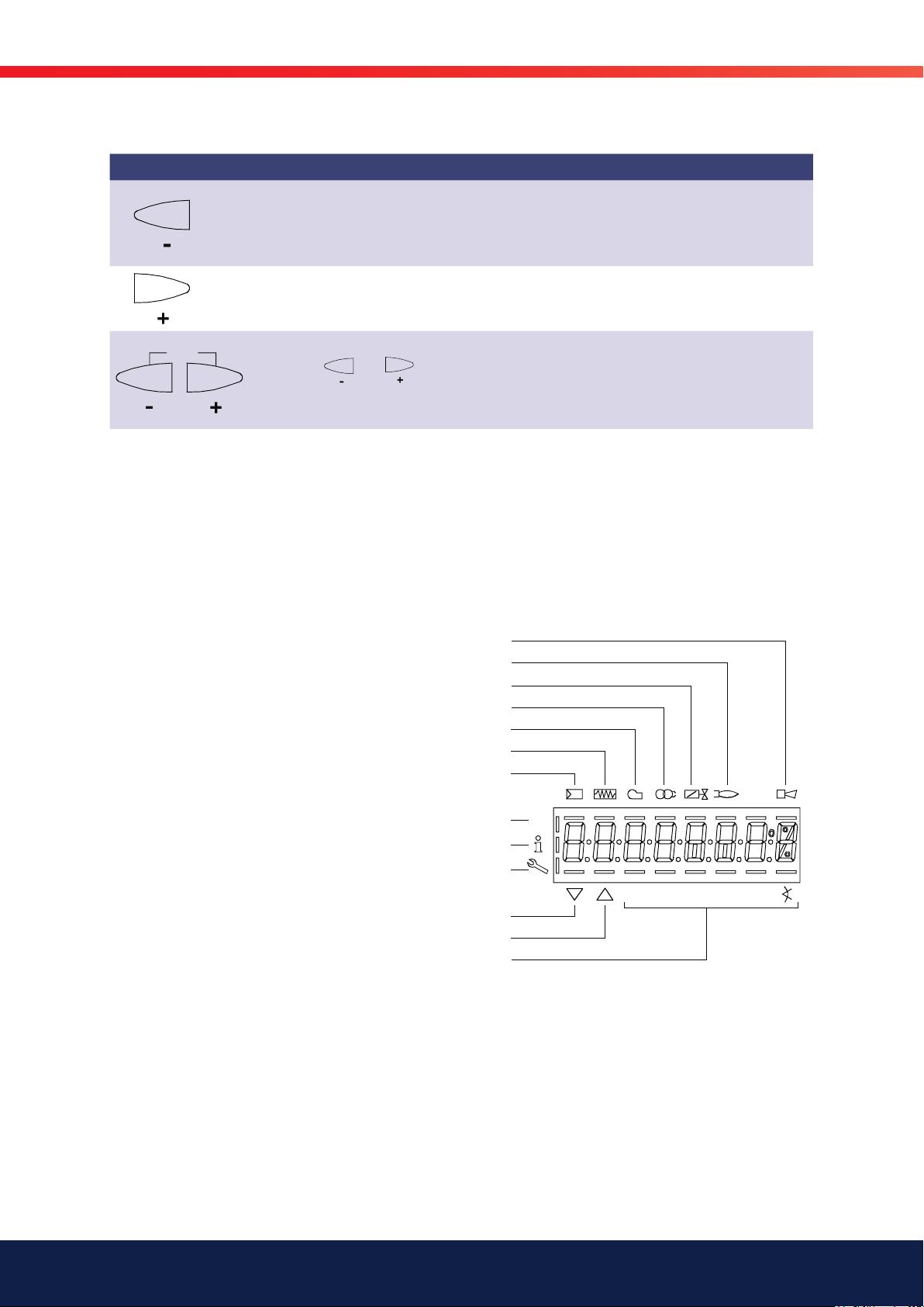
General
ESC
Button Function
- button
- For decreasing the value
- For navigating during curve adjustments in info or service mode
+ button
- For increasing the value
- For navigating during curve adjustments in info or service mode
+ and - button: Escape function
(press
- No adoption of value
- One menu level up
and simultaneously)
Fault status message
Flame present
Valve controlled
Ignition controlled
Fan motor controlled
Oil preheater on
Heat request from controllers
Parameter setting mode
Info mode
Service mode
Actuator closing
Actuator opening
Unit of current display
Figure 4: Meaning of display
P
V h
min
s %
78
Bentone
Page 79

15.2 List of phase displays
The display shows which phase the burner is in. The table below lists the
codes and explains what these mean for the various phases. Not all the
phases described in the table are shown or are suitable for the burners
described in this manual.
Phase Function
Ph00 Lockout phase
Ph01 Safety phase
Ph10 Home run
Ph12 Standby (stationary)
Ph22 Fan ramp up time (fan motor = ON, safety valve = ON)
Ph24 Traveling to the prepurge position
Ph30 Prepurge time
Ph36 Traveling to the ignition position
Ph38 Preignition time
Ph39 Valve proving filling time
(test of pressure switch-min when fitted between fuel valves V1 and V2)
Ph40 1st safety time (ignition transformer ON)
Ph42 1st safety time (ignition transformer OFF)
Ph44 Interval 1
Ph50 2nd safety time
Ph52 Interval 2
Ph60 Operation 1 (stationary)
Ph62 Max. time low-fire (operation 2, preparing for shutdown, traveling to low-fire)
Ph64 Switching back to pilot: Modulation to ignition load
Ph65 Switching back to pilot: Interval 2 waiting time
Ph66 Switching back to pilot: Reactivation of ignition + pilot
Ph67 Switching back to pilot: Shutdown of main valves
Ph68 Switching back to pilot: Pilot mode waiting phase
Ph69 Switching back to pilot: Pilot mode waiting phase for burner startup
Ph70 Afterburn time
Ph72 Traveling to the postpurge position
Ph74 Postpurge time (no extraneous light test)
Ph78 Postpurge time (t3) (abortion when load controller ON)
Ph80 Valve proving test evacuation time
Ph81 Valve proving test time atmospheric pressure, atmospheric test
Ph82 Valve proving filling test, filling
Ph83 Valve proving time gas pressure, pressure test
Ph90 Gas shortage waiting time
General
79 Bentone
Page 80

General
15.3 Automatic control unit levels
When working on burners there are different levels at which the automatic
control unit can be accessed.
The info and service levels can be accessed without a password; error
codes, error history and basic information about the burner can be viewed
on these levels.
A code is required to enter settings for the burner.
Normal display
>1 s
/reset
Change to normal
Change to normal
display
display
>3 s
Info level
>3 s
<8 s
/reset
or
<8 s
/reset
or automatic return
Service level
after timeout of
menu operation
(parameter 127)
>8 s
80
Bentone
>1 s
Parameter level
Parameter level
Page 81

15.3.1 Structure of parameter levels
Internal parameter
(password level)
General
/reset
!
Entering the password
Air-fuel ratio control curves
(primary setting)
Bild 388e/1109
The following sections explain the
operating philosophy behind the
parameter levels using a number of
/reset
General
/reset
Basic unit
/reset
/reset
Air-fuel ratio control
/reset
Actuator
examples.
Error histery
Process data
/reset
/reset
81 Bentone
Page 82

General
15.3.2 Parameter of level info
No. Parameter
167 Fuel volume resettable (m³, l, ft³, gal)
162 Operating hours resettable
164 Startups resettable
163 Operating hours when unit is live
166 Total number of startups
113 Burner identification
107 Software version
108 Software variant
102 Identification date
103 Identification number
104 Preselected parameter set: Customer code
105 Preselected parameter set: Version
143 Reserve
End
15.3.3 Parameter of level service
No. Parameter
954 Flame intensity
960 Actual flow rate (fuel throughput in m³/h, l/h, ft³/h, gal/h)
121 Manual output
Undefined = automatic operation
922 Incremental position of actuators
Index 0 = fuel
Index 1 = air
936 Standardized speed
161 Number of faults
701
.
.
.
725
Error history: 701-725.01.Code
ex. 701. 01. xxx
chronological error list index value of index
Indexlista:
01 = error code
02 = diagnostic code
03 = error class
Bentone
82
04 = error phase
05 = startup counter
06 = output
Page 83

VSD
AF
V h
min
s %
Bild 43/1107
Bild 44/1207
/reset
15.3.4 Access code for service engineer level
The code for logging into service level is found on the plate on the inside of the cover for the electrical
!
connections box.
General
Press button combination
When releasing the buttons, 7 bars appear the first of whishes.
P
Press
P
Press
or
V
to confirm the value
to select a number or letter.
s %
min
h
to display CodE
83 Bentone
Page 84

General
V h
min s %
Bild 45/1207
V h
min s %
Bild 47/1207
/reset
The value entered changes to a minus sign (-)
P
Complete the rest of the password according to the principle described.
P
After entery of the last character the password must be confirmed by pressing
The next bar starts flashing.
Example: Password consisting of 4 characters.
84
Bentone
Page 85

V h
min
s %
Bild 95/0707
VSD
AF
V h min s %
Bild 94/0707
/reset
V h min s %
Bild 96/0707
/reset
15.4 Setting the automatic control unit
To set the correct ratio between air and fuel, it is important to understand
how this type of burner is controlled. This chapter will describe the procedure
to follow when adjusting a burner with an LMV37 automatic control unit.
Note! When power is turned on for an unadjusted automatic control
unit, “OFF UPr” is always shown in the display.
!
15.3.5 Setting an automatic control unit which has
not previously been set or lost its settings
Check that the burner is receiving power and that gas is being supplied to
the burner.
Move the switch (X) on the burner to the ON position.
The text “OFF UPr” is shown in the display.
Follow the procedure indicated below to set the automatic control unit.
General
X
An unprogrammed unit or a unit whose operating mode has been reset or
P
Press
To continue with the setting work, you need to log into service engineer level. See 5.3.4.
After login is complete, continue with the setting work as shown below.
P
Press
P
> 1 second to access login mode.
to select parameter 400 for initial commissioning and for setting air-fuel controll.
changed displays OFF U Pr.
201: appears fl ashing.
Press
201 for selecting the operating mode.
to go to the settings for air-fuel ratio control and parameter
85 Bentone
Page 86

General
Ensure that the fuel train is correctly set in compliance with the type of burner used.
!
No Parameter Actuator controlled
201 Burner operating mode (fuel train, modulating / multistage, actuators, etc.) Air Fuel
-- = undefined (delete curves) • •
1 = gas modulating (G mod) • •
2 = gas modulating with pilot valve (Gp1 mod) • •
3 = gas modulating with pilot valve (Gp2 mod) • •
4 = oil modulating (Lo mod) • •
5 = oil 2-stage (Lo 2 stage) • -
6 = oil 3-stage (Lo 3 stage) • -
7 = gas modulating (G mod pneu) • -
8 = gas modulating (Gp1 mod pneu) • -
9 = gas modulating (Gp2 mod pneu) • -
10 = oil modulating with gas pilot (LoGp mod) • •
11 = oil 2-stage with gas pilot (LoGp 2-stage) • -
12 = oil modulating with 2 fuel valves (Lo mod 2V) • •
13 = oil modulating with gas pilot and 2 fuel valves (LoGp mod 2V) • •
14 = gas modulating (G mod pneu, 0 active) - -
15 = gas modulating with pilot (Gp1 mod pneu, 0 active) - -
16 = gas modulating with pilot (Gp2 mod pneu, 0 active) - -
17 = oil 2-stage (Lo 2-stage, 0 active) - -
18 = oil 3-stage (Lo 3-stage, 0 active) - -
19 = gas modulating only when firing on gas (G mod fuel active) - •
20 = gas modulating with pilot only when firing on gas (Gp1 mod fuel active) - •
21 = gas modulating with pilot only when firing on gas (Gp2 mod fuel active) - •
22 = oil modulating only when firing on oil (Lo mod fuel active) - •
86
Bentone
Page 87

ESC
/reset
ESC
V h min s %
Bild 96/0707
V h
s
min %
Bild 100/0807
/reset
/reset
ESC
This manual describes “1=gas modulating (Gmod)” type burners.
!
General
Press:
Press:
P
To the next parameter
P
to return to parameter level.
Press
to return to parameter level.
l
Parameter 542 to
activate the VSD / PWM fan.
You can choose:
0 = VSD / PWM fan OFF
1 = VSD / PWM fan ON
to save selected setting.
If the parameter is set correctly, move directly to the next parameter with
Press
Select your setting by pressing one of the buttons
Press
Press:
To the next parameter
to adjust parameter 542.
to save the setting for parameter 542: VSD
to return to parameter level.
Back to the previous parameter
This manual describes “0=VSD
OFF” type burners.
!
87 Bentone
Page 88

General
V
h
s
min %
Bild 101/0807
/reset
/reset
ESC
V h
min
s %
Bild 102/0707
F
V h
min
s %
Bild 104/0707
A
Parameter 641 to control speed standardization of the VSD.
P
If the parameter is set correctly, move directly to the next parameter with
You can choose:
0 = speed standardization of VSD OFF
1 = speed standardization of VSD ON
After setting speed standardization to 1, standardization of the VSD
commences. If successful, the parameter is reset to 0. Negative values
indicate errors (refer to chapter Automatic speed standardization).
Press:
Select your setting by pressing one of the buttons
Press:
Press:
To the next parameter
P
Press simultaneously
to adjust parameter 641: speed standardization
to save the setting for parameter 641: VSD
to return to parameter level.
Display P0 appears flashing.
Curvepoint for ignition load.
and
Set a suitable fuel-air mixture so that the burner starts.
or
!
This manual describes
“0=speed standardization” type
!
burners.
to set ignition position P0 of the fuel damper.
Example: 30.0
P
Press simultaneously
88
Bentone
and
or
to set ignition position P0 of the air actuator.
Page 89

General
V h
min
s %
Bild 107/0707
F
A
V h
s
min %
Bild 110/0807
V h
min
s %
Bild 112/0707
Example: 22.0
P
Press simultaneousl
This menu option is only shown if parameter 542 has been set to 1, for burners with VSD.
This manual only describes burners without VSD.
!
P
To the next curvepoint
P
and
and
Example: 20.0
P9 appears flashing.
Curvepoint for high-fire.
Same procedure as with P0
!
or
Note:
If
to adjust speed nO of the load controller.
is pressed first, the display jumps to 90!
Back to the previous curvepoint
When curvepoint 9 is set, press
to start the burner.
89 Bentone
Page 90

General
)
Air
Angle
Curvepoints
It is important to set P0 and P9 as accurately as possible.
These settings are used to calculate the remaining
Air
curvepoints once the burner has started.
Fuel
Curvepoints P2 to P8 are automatically computed as a straight line
between P1 and P9.
Example 1 = gas modulating
Curvepoint Value 1 fuel Value 2 air
Curvepoint P1 is automatically
set to the same value as P0 on
P0, P1 and P9 are set as described
P0 30.0 22.0
P1 32.0 24.0
the first start. This value can,
however, be adjusted once the
burner has started.
P9 80.0 90.0
Curvepoint Value 1 fuel Value 2 air
P2 38.0 32.3
P2 through P8 have automatically
been calculated:
P3 44.0 40.5
P4 50.0 48.8
P5 56.0 57
P6 62.0 65.3
P7 68.0 73.5
P8 74.0 81.8
To simplify the setting work involved for each curvepoint, do as follows:
1. Check that good combustion is achieved at P1; adjust if necessary.
2. Move along to P2 and check/adjust for good combustion.
3. Calculate the curvepoints between P2 and P9 by pressing > on
.
4. Now move along to P3 and repeat the process described.
5. Repeat the process until curvepoint P9 has been reached.
This method makes the setting work easier and faster to complete. A more “correct”
setting is obtained straight away. The process may need to be redone if the wrong
input power was set for P9 initially. For this reason, be extremely careful when entering
the first setting of P9.
Bentone
90
Page 91

General
V h
min
s %
Bild 113/0707
/reset
V h
min
s %
Bild 114/0707
V h
min
s %
Bild 10/0707
V h
min
s %
Bild 115/0707
V h
min
s %
Bild 116/0707
V h
min
s %
Bild 117/0707
Identification of start for setting the curve parameters.
P
Press
to continue.
The burner motor will then start and a number of phases in the automatic control unit are completed. A menu then
appears, asking whether further changes to ignition load P0 need to be made.
If the switch on the burner is in the OFF position, the automatic control unit will not proceed from Ph12: Move the
switch to the ON position to continue.
Phase Standby (stationary)
P
Phase Fan ramp up (fan motor = ON, safety valve = ON)
P
Phase Traveling to prepurge position
P
Phase Prepurging
P
P
Phase Traveling to ignition position
91 Bentone
Page 92

General
V h
min
s %
Bild 118/0707
F
A
V h
min
s %
Bild 117/0707
V h
min
s %
Bild 119/0707
V h
min
s %
Bild 120/0707
V h
min
s %
Bild 121/0707
V h
min
s %
Bild 122/0707
P
Ignition position P0 can only be set after
symbol
or is no longer highlighted.
When the symbol
press
P
P
to continue.
For fuel, keep
press
or is no longer highlighted,
Phase Traveling to ignition position
Phase Preignition
depressed, for air
or
,
to adjust the value.
Phase for first safety time (ignition transformer ON)
P
Phase for first safety time (ignition transformer OFF), preignition time OFF
P
Phase Interval 1
P
Bentone
92
Page 93

General
V h
min
s %
Bild 118/0707
F
A
V
h
min
s %
Bild 123/0707
F
A
The burner has ignited and is burning. Should the burner not ignite, repeat the above procedure but adjust ignition
load P0 to get the burner to start.
The P0 menu will appear when the burner starts successfully.
It is now possible to adjust ignition load P0 while the burner is in operation.
Ignition position P0 can only be set when
symbol
P
For fuel, keep
or is no longer highlighted.
depressed, for air
,
When the symbol
press
P
to continue to the next curvepoint.
press
or is no longer highlighted,
Low flame position P1 can only be set when
symbol or is no longer highlighted.
The value is adopted from P0
For fuel, keep
press
When symbol
or
to adjust the value.
depressed, for air
or
to adjust the value.
or is no longer highlighted.
,
93 Bentone
Page 94

General
V h
min
s %
Bild 124/0707
ESC
V h
min
s %
Bild 126/0707
/reset
/reset
ESC
Back to the previous curvepoint
When the symbol or is no longer highlighted,
press
P
!
Move along to curvepoint (high-fire point) P9; allow the burner to reach high-fire point P9.
When P9 flashes, press
!
to start calculating curvepoints.
When changing from P1 to P2 for the first time, curvepoints P2…P8
automatically calculated and saved.
CALC appears for a short moment.
When reviewing curvepoints after calculating them, check and adjust each curvepoint in order to achieve
good combustion.
If the burner goes into blocking mode when increasing to full load, restart the setting procedure and adjust
the curvepoints in order to avoid the burner entering blocking mode.
The maximum capacity is displayed.
P
The benefit of setting the maximum input power in this way is that at a
later date it is easy to change the input power without having to adjust the
amount of air and gas. The setting curve is therefore adjusted to the highest
input power that the installation can handle. The desired input power is then
set by entering how much of the maximum power is required.
If the display shows - - - -, the maximum capacity has not yet been
specified.
The system can be run up to 100%.
You can press
maximum capacity.
Adjust the setting downwards or upwards using the buttons
Press
Press
to go to editing mode, enabling you to change the
to save the setting.
to return to parameter level.
94
Bentone
Page 95

General
V h
min
s %
Bild 127/0707
/reset
/reset
ESC
ESC
V h min s %
Bild 94/0707
ESC
V h
min
s %
Bild 128/0707
To the next parameter
The minimum capacity is displayed.
P
If the display shows - - - -, the minimum
capacity has not yet been entered.
The system can be run down to 20%.
You can press
to go to editing mode, enabling you to
change the minimum capacity.
Adjust the setting downwards or upwards using the buttons
Press
Press
to save the setting.
to return to parameter level.
The benefit of setting the minimum input power in this way is that at a
later date it is easy to change the input power without having to adjust the
amount of air and gas. The setting curve is therefore adjusted to the lowest
input power that the installation can handle. The desired input power is then
set by entering how much of the minimum power is required.
Completing parameterization of the curve
Back to the previous parameter
When symbol or is no longer highlighted, you can press ESC a
P
Press
P
to exit parameter level.
second time.
The settings for air-fuel ratio control by the LMV37.4... are now completed.
95 Bentone
Page 96

General
15.4.1 The parameters below may need to be set
according to the nature of the installation.
To change any of the parameters set out below, go into parameter level and
make the required adjustments.
15.4.1.1 Pressure switch-min input
236 Gas: Pressure switch-min input
0 = inactive
1 = pressure switch-min (upstream of fuel valve 1)
2 = valve proving via pressure switch-min (between fuel
valves 1 and 2)
Factory settings marked with bald text.
15.4.1.2 Execution valve proving
241 Gas: Execution valve proving
0 = no valve proving
1 = valve proving on startup
2 = valve proving on shutdown
3 = valve proving on startup and shutdown
Factory settings marked with bald text.
At an input power higher than 1,200 kW, a tightness test must be performed.
At an input power lower than 1,200 kW, performing a tightness
test is optional. It is essential for all changes to take local
standards and regulations into consideration.
15.4.1.3 No-flame positions fuel actuator
501 No-flame positions fuel actuator
Index 0 = no-load position
Index 1 = pre purge position
Index 2 = post purge position
Factory settings marked with bald text.
15.4.1.4 No-flame positions air actuator
502 No-flame positions air actuator
Index 0 = no-load position
Index 1 = pre purge position
Index 2 = post purge position
Factory settings marked with bald text.
This manual describes “2=valve proving via
pressure switch-min (between fuel valves 1
!
and 2)” type burners.
Depending on the type of burner, the
automatic control unit should be set to
!
either “0=no valve proving” or “1=valve
proving on startup”.
The automatic control unit should be set to
“Index 0 = no-load position”.
!
The automatic control unit should be set to
!
“Index 0 = no-load position”.
15.4.1.5 Active detector flame evaluation
221 Gas: Active detector flame evaluation
0 = QRB / QRC
1 = ION / QRA
Factory settings marked with bald text.
When replacing detector flame between ionisation and UV-cell (QRA), no
change to the setting parameters is required; simply disconnect and connect
ionisation and UV-cell (QRA) respectively..
Bentone
96
Page 97

15.4.1.6 Prepurging
222 Gas: Prepurging
Index 0 = deactivated
Index 1 = activated
Factory settings marked with bald text
When using valve proving and 2 fuel valves of class A, prepurging is not
required (conforming to EN 676).
If not activated, it is nevertheless performed if one or several of the following
conditions apply:
• Alterable lockout position
• After an off time of >24 hours
• In the event of a power failure (power-on)
• In the event of shutdown due to an interruption of gas supply (safety
shutdown)
General
15.4.1.7 Prepurging time
225 Gas: Prepurging time
20 s – 60 min
15.4.1.8 Postpurge time
234 Gas: Postpurge time (no external light test)
0,2 s – 108 min
15.4.1.9 Postpurging in lockout position
190 Postpurging in lockout position
0 = deactivate (no-load position)
1 = active (postpurge position)
Factory settings marked with bald text.
When the Purging in the lockout position function is used, the fan may only be powered via a contactor
!
and must not be connected directly to LMV37.4 (X3-05 pin 1)!
97 Bentone
Page 98

General
When active, the Alarm in the event of start prevention function (parameter
210) is only possible to a limited extent!
The LMV37.4 system simply moves the actuators to the postpurge position.
A fan release contact cannot be controlled, as the alarm relay of the
LMV37.4 system cuts off the power supply to the outputs. With the Alarm in
the event of start prevention function, an external circuit that may be present
for controlling the fan release contact for purging in the lockout position is
activated via start prevention in standby mode.
15.4.1.10 Continuous fan
A burner can be converted into a continuous fan using conversion kit
119 230 01. See the documentation provided with the kit for instructions on
how to perform the conversion.
15.4.1.11 Continuous operation
The LMV37 automatic control unit permits continuous operation of the
burner, provided that the burner’s detector flame is an ionisation detector
flame.
When forced intermittent operation is activated, the unit shuts down for a
moment after 23 hours and 45 min of uninterrupted operation, followed by
an automatic restart.
When forced intermittent operation is inactivated the burner will run
continuously.
Forced intermittent operation is a standard feature.
239 Gas: Forced intermittent operation
0 = inactivate
1 = activated
Factory settings marked with bald text.
98
Bentone
Page 99

V h min s %
Bild 94/0707
/reset
V h
min
s %
Bild 113/0707
15.4.2 Adjusting settings of previously set
VSD
AF
automatic control unit
With the warm settings, the burner is started up after pressing the Info button. Air-fuel ratio control can
now be accurately set while the fl ame is present. When traveling along the precalculated curve to high-fi re
!
point P9, all intermediate curvepoints (P2…P8) must be set.
Automatic operation is released when – after reaching P9 – the curve settings are quit by pressing ESC. If
the curve settings are aborted earlier (ESC or shutdown due to fault), start prevention OFF UPr continues
to be active until all points are set.
If required, the gas pressure can be set at the high-fi re point. In case the gas pressure is changed, all
points must be checked by traveling along the curve downward and – if required – must be readjusted.
safety shutdown, parameterization of the curve is quit.
General
Check that the burner is connected to gas and has gas pressure.
Check that the burner is connected to an electrical supply.
Move the switch X to the ON position.
The display Y on the burner will now be active.
Follow the description below to set the burner.
Press
To continue with the setting work, you need to log into service engineer
level. See 5.3.4.
After login is complete, continue with the setting work as shown below.
P
Press
> 1 second to access login mode.
to select parameter 400 for initial commissioning and for setting air-fuel ratio control
XY
P
Identifi cation of start for setting the curve parameters.
99 Bentone
Page 100

General
/reset
V
h
min
s %
Bild 123/0707
F
A
When there is a request for heat.
If, during the time the curve is parameterized, an error occurs which leads to safety shutdown,
!
parameterization of the curve is quit.
The startup process on the automatic control unit now takes place. To see
what happens in each phase, go to chapter 3.3.
When the automatic control unit has completed the start procedure and the
burner has started, the setting values for curvepoint 1 will appear; settings
for the minimum input power will be shown in the display. See display
representation below. If you wish to adjust the ignition load,
this can be done by pressing
display.
P
To the next curvepoint
when curvepoint 1 is shown in the
Low-flame position P1 can only be set when symbol or is no longer
highlighted.
The value is adopted from P0.
For fuel, keep
Press
When symbol
curvepoint P2 can be selected with
back to the previous curvepoint
and
depressed, for air
or is no longer highlighted, the next
,
to adjust the value.
100
Bentone
 Loading...