

Page 1

178 116 35-5 2017-12–05
Providing sustainable energy solutions worldwide
Installation- and maintenance instruction
BF1 RME
Page 2

Page 3

Table of contents
General
GENERAL
1. GENERAL INSTRUCTIONS
__________________________________________4
1.2 Manual ____________________________________________________________________4
1.3 Safety directions ______________________________________________________4
1.1 General rules ___________________________________________________________4
1.1 Model BF1 FUV 63-16 ______________________________________________6
1.1.1 Burner output/ Basic settings _________________________6
1.2 Model BF1 KV 76-26 ________________________________________________7
1.2.1 Burner output/ Basic settings _________________________7
2. TECHNICAL DATA
_______________________________________________________8
2.1 Dimensions BF1 _______________________________________________________8
2.1.1 Dimensions, flanges _______________________________________ 8
2.2 Recommended nozzles and pressures _______________________9
2.3 Nozzle table, 8-15 bar ______________________________________________9
2.3.1 Burner with preheater ____________________________________9
2.4 Description ____________________________________________________________10
2.4.1 Components _______________________________________________11
3. INSTALLATION
__________________________________________________________12
3.1 Delivery checks ______________________________________________________12
3.2 Preparations for installation _____________________________________12
3.3 Oil supply ______________________________________________________________12
3.4 Electrical connection _______________________________________________12
3.5 Choice of nozzle ____________________________________________________12
3.6 Brake plate and airflow setting _________________________________12
3.7 Burner installation ___________________________________________________ 13
3.7.1 Hole pattern ________________________________________________13
3.7.2 Burner installation ________________________________________13
3.7.3 Oil pipes _____________________________________________________ 13
3.7.4 Electrical connection ____________________________________ 13
4. BASIC SETTINGS
______________________________________________________14
4.1 Example of basic setting _________________________________________14
4.1.1 Choice of nozzle __________________________________________ 14
4.1.2 Basic setting _______________________________________________ 14
4.1.3 Nozzle assembly adjustment ________________________ 15
4.1.4 Air intake adjustment ___________________________________ 15
4.1.5 Method of adjusting air quantity ____________________ 15
4.1.6 Inlet cone, air adjustment _____________________________ 15
4.1.7 Air intake rotation ________________________________________ 16
4.1.8 Air duct ______________________________________________________ 16
5. BURNER SERVICING
________________________________________________17
5.1 Warning ________________________________________________________________17
5.1.1 Service position ___________________________________________ 17
5.1.1.1 Service position 1 ______________________________________17
5.1.1.2 Service position 2
5.1.1.3 Service position 3
______________________________________17
______________________________________18
5.1.2 Combustion assembly service ______________________ 18
5.1.3 Preheater replacement _________________________________ 19
5.1.4 Oil pump replacement __________________________________ 20
5.1.5 Fan motor replacement ________________________________ 21
5.1.6 Air intake and intake cone service _________________ 22
5.1.7 Fan wheel checks ________________________________________ 22
5.1.7.1 Inspection ______________________________________________22
5.1.7.2 Cleaning, alternative 1
5.1.7.3 Cleaning, alternative 2
__________________________________23
__________________________________24
5.1.8 Electrical module _________________________________________ 24
5.1.8.1 Replacement of complete electrical package __________25
5.1.8.2 Replacement of individual electrical components
______25
6. PUMP INSTRUCTIONS ______________________________________________ 26
6.1 Suntec ANV47C _____________________________________________________26
6.1.1 Technical data ____________________________________________26
6.1.2 Components _______________________________________________26
6.1.3 Filter replacement ________________________________________ 27
6.1.4 One-pipe system ________________________________________ 27
6.1.5 Two-pipe system _________________________________________27
6.1.6 Solenoid valve _____________________________________________ 27
6.1.7 Function ANV47C ________________________________________ 28
6.1.8 Suction pipe tables ANV47C ________________________ 29
6.1.8.1 Overhead Tank _________________________________________29
6.1.8.2 Underlying Tank
________________________________________29
7. PREHEATER ______________________________________________________________ 30
7.1.1 Function FPHE 5 _________________________________________ 30
8. ELECTRICAL EQUIPMENT
LMO1..2..4..
____________________________________________________________31
8.1 Wiring diagram ______________________________________________________ 31
8.1.1 Component list____________________________________________ 32
8.1.2 Function LMO1..2..4.. __________________________________ 32
8.1.3 Technical data _____________________________________________33
8.1.4 Colour codes LMO14/24______________________________ 34
8.1.5 Fault codes LMO14/24 ________________________________ 34
9. FAULT LOCATION
______________________________________________________35
9.1 Burner will not start ________________________________________________ 35
9.2 Burner will not start after normal use ________________________ 35
9.3 Delayed ignition, burner starts; pulsation ___________________ 35
10. DECLARATION OF CONFORMITY
11. OIL BURNERS MAINTENANCE INSTRUCTIONS
_____________________________36
________37
3 Bentone BF1
Page 4

General
1. GENERAL INSTRUCTIONS
1.2 Manual
• The contents of this manual are to be observed by all who work for any
reason on the unit and its appertaining system parts.
• This manual is intended especially for authorised personnel.
• This manual is to be regarded as part of the burner and shall always be
available near the place of installation.
1.3 Safety directions
The electrical installation shall be made according to valid regulations for
heavy current and in a professional way, so that the risk of leaking oil, fire or
personal injury is avoided.
Care should be taken by the installer to ensure that no electrical cables or
fuel/gas pipes are trapped or damaged during installation or service/
maintenance.
1.1 General rules
This is a burner designed for FAME (RME) fuel. The fuel must meet the
requirements of standard EN 14214 for FAME. The equipment on the burner
is, however, of such a quality that it is possible to use EO1 type oil without
modification, although with appropriate adjustments to the combustion
values after each change of fuel type.
The installation of an oil burner should be carried out in accordance with
local regulations. The installer of the burner must therefore be aware of all
regulations relating to oil and combustion.
Only oil suitable for the burner must be used and then in combination with a
suitable oil filter designed for FAME (RME) and installed before the burner’s oil
pump.
If the burner is replacing an existing burner, ensure that the oil filter is
changed to a filter designed for FAME (RME). Installation may only be
performed by qualified personnel.
Care should be taken by the installer to ensure that no electrical cables
or fuel/gas pipes are trapped or damaged during installation or service/
maintenance.
Burners which are fuelled by FAME (RME) are and must be equipped with
parts designed for this fuel. This applies in particular to oil-related parts such
as the pump, solenoid valve, oil filter and hoses. It is very important when
carrying out a service to replace old parts with new parts of the same quality.
4
Bentone BF1
Page 5

General
Adjustment of burner
The burner is from the factory preset to an average value
that must then be adjusted to the boiler in question.
All burner adjustments must be made in accordance with
boiler manufacturers instructions.These must include
the checking of flue gas temperatures, average water
temperature and CO2 or O2 concentration.
To adjust the combustion device, start by increasing the
air volume and the nozzle assembly somewhat. When
the burner starts it is burning with excess air and smoke
number 0. Reduce the nozzle assembly adjustment
until soot occurs, and then increase the adjustment to
make the soot disappear again. Then the volume of air is
reduced until soot occurs and increased again to reach a
combustion free of soot.
By this procedure an optimum adjustment is obtained. If
larger nozzles are used the preadjustment of both the air
volume and the nozzle assembly must be increased.
A whistling sound may be heard which can be
eliminated or reduced as follows: Increase the nozzle
assembly adjustment somewhat. The CO2-content and
consequently the air volume will then be reduced.
Condensation in chimney
A modern burner works with less excess air and often
also with smaller nozzles than older models. This
increases the efficiency but also the risk of condensation
in the chimney. The risk increases if the area of the
chimney flue is too large. The temperature of the flue
gases should exceed 60°C measured 0,5 metres from
the chimney top.
Pump adjustment
See separate description.
Maintenance
The boiler/burner should be examined regularly for any
signs of malfunction or oil leakage. Any boiler/burner that
uses FAME (RME) as fuel must be serviced at least twice
a year.
Installation instructions
General installation instructions ac company the burner
and should be left in a prominent place adjacent to the
burner.
Oil supply
The oil line should be dimensioned in accordance with
the pump manufacturer´s instruction. A filter designed for
FAME (RME) that prevents any particles in the oil from
reaching the burner is mounted in the burner’s suction
pipe. If the installation consists of several burners each
one should have its own suction line from the tank or a
circulation system should be used.
The temperature in the oil line should be kept as
constant as possible. Avoid exposing the line to
excessive cold which may cause blockages.
The oil pipe and electric cable should be fitted so that
the burner can be placed on the floor for inspection of
the combustion device.
Oil hoses must be of a quality designed for FAME (RME).
• Measures to raise the temperature:
• Insulate the chimney in cold attics
• Install a tube in the chimney
• Install a draught regulator (dilutes the flue gases
during operation and dries them up during
standstill)
• Increase the oil quantity
• Raise the flue gas temperature by removing
turbulators, if any, in the boiler.
Detailed ecodesign information can be downloaded at:
www.bentone.com/ecodesign
5 Bentone BF1
Page 6

General
1.1 Model BF1 FUV 63-16
ø16
ø67
ø63
Protrusion from flange, measurement B
Length of blast tube
Flange
1 2 3 4
103 68 81 89 88
133 98 111 119 118
183 148 161 169 168
1.1.1 Burner output/ Basic settings
1,3 - 4,6 kg/h
15 - 55 kW
4,0
3,5
3,0
2,5
2,0
1,5
1,0
0,5
Boiler overpressure, mbar
0,0
-0,5
10 15 20 25 30 35 40 45 50 55 60
Burner output, kW
22,0
20,0
Scale
18,0
16,0
14,0
12,0
10,0
8,0
6,0
4,0
2,0
0,0
15 20 25 30 35 40 45 50 55
1,6–2,0
7,0–8,0
Air settings
Nozzle assembly
(-0,1)+0,5
Burner output, kW
6
Scale value applies to 0 mbar furnace pressure.
!
Bentone BF1
Page 7

4,0
1.2 Model BF1 KV 76-26
General
ø26
ø70
ø76
Protrusion from flange, measurement B
Length of blast tube
1 2 3 4
117 82 95 103 102
147 112 125 133 132
197 162 175 183 182
Flange
1.2.1 Burner output/ Basic settings
3,8 - 8,0 kg/h
25 - 75 kW
8,0-9,0
2,7-3,3
0,5-1,5
3,5
3,0
2,5
2,0
1,5
Boiler overpressure, mbar
1,0
0,5
0,0
-0 ,5
40 4 5 50 5 5 60 6 5 7 0 75 80 8 5 90 9 5 10 0
Burner output, kW
Scale value applies to 0 mbar furnace pressure.
!
7 Bentone BF1
Page 8

General
2. TECHNICAL DATA
2.1 Dimensions BF1
B
ø89
145
305
226
172
190
2.1.1 Dimensions, fl anges
Flange 1 Flange 2
10,3
Flange 3 Flange 4
10
ø89,7
130–150
ø90
125
25
12
4
10,3
ø89,5
136–150
ø90
125–150
12
5
8
Scale value applies to 0 mbar furnace pressure.
!
Bentone BF1
Page 9

General
2.2 Recommended nozzles and pressures
Because of the different types of boiler in existence, with varying furnace
geometries and furnace loads, it is not possible to commit to any given spray
angle or spay pattern. Note that spray angles and spray patterns change
with pump pressures.
Nozzle 60° Solid/Hollow cone
80° Solid/Hollow conel
Pump pressure 10 bar (8–14 bar) Fuel oil 1, RME
Kerosene
2.3 Nozzle table, 8-15 bar
Pump pressure, bar
Gph 8 9 10 11 12 13 14 15
kg/h kW kg/h kW kg/h kW kg/h kW kg/h kW kg/h kW kg/h kW kg/h kW
0,40 1,33 16 1,41 17 1,49 18 1,56 18 1,63 19 1,70 20 1,76 21 1,82 21
0,50 1,66 20 1,76 21 1,86 22 1,95 23 2,04 24 2,12 25 2,20 26 2,28 27
0,60 2,00 24 2,12 25 2,23 26 2,34 28 2,45 29 2,55 30 2,64 31 2,73 32
0,65 2,16 26 2,29 27 2,42 29 2,54 30 2,65 31 2,75 33 2,86 34 2,96 35
0,75 2,49 29 2,65 31 2,79 33 2,93 35 3,08 36 3,18 38 3,30 39 3,42 40
0,85 2,83 33 3,00 36 3,16 37 3,32 39 3,47 41 3,61 43 3,74 44 3,87 46
1,00 3,33 39 3,53 42 3,72 44 3,90 46 4,08 48 4,24 50 4,40 52 4,56 54
1,10 3,66 43 3,88 46 4,09 48 4,29 51 4,48 53 4,67 55 4,84 57 5,01 59
1,20 3,99 47 4,24 50 4,47 53 4,68 55 4,89 58 5,09 60 5,29 63 5,47 65
1,25 4,16 49 4,40 52 4,65 55 4,88 58 5,10 60 5,30 63 5,51 65 5,70 68
1,35 4,49 53 4,76 56 5,02 59 5,27 62 5,50 65 5,73 68 5,95 70 6,15 73
1,50 4,98 59 5,29 63 5,58 66 5,85 69 6,11 72 6,36 75 6,60 78 6,83 81
1,65 5,49 65 5,82 69 6,14 73 6,44 76 6,73 80 7,00 83 7,27 86 7,52 89
1,75 5,82 69 6,18 73 6,51 77 6,83 81 7,14 85 7,42 88 7,71 91 7,97 94
2,00 6,65 79 7,06 84 7,45 88 7,81 93 8,18 97 8,49 101 8,81 104 9,12 108
2,25 7,49 89 7,94 94 8,38 99 8,78 104 9,18 109 9,55 113 9,91 117 10,26 122
The table applies to oils with a viscosity of 4.4 mm
2
/s (cSt) at a density of 830 kg/m3.
2.3.1 Burner with preheater
Allow for a reduction in oil quantity of 5–20% with preheating owing to:
• Temperature increases at the nozzle.
• Nozzle design.
• Capacity (the higher the capacity the lower the difference).
9 Bentone BF1
Page 10

General
2.4 Description
1
2
10
3 4
5
6
7
9
2.4.1 Components
1. Brake plate
2. Nozzle
3. Fan housing, front
4. Ignition transformer
5. Separating screw
6. Oil burner control
7. Electrical contact X3 (refer to wiring diagram)
8. Motor
9. Capacitor
10. Preheater, where fitted
11. Ignition electrode
12. Ignition cable
8
13. Photoresistor
14. Inspection glass
15. Nozzle assembly adjustment
16.
17. Blast tube
18. Grid
19. Solenoid valve
20. Oil pump
21. Air regulator
22. Air intake
23. Air flow indicator
24. Fan housing, rear
10
Bentone BF1
Page 11

General
3
15
13
5
17
14
19
20
24
22
21
1
23
2
11 12
10
11 Bentone BF1
Page 12

General
3. INSTALLATION
3.1 Delivery checks
Check that everything has been delivered and that the goods are not
transport damaged. Any delivery faults must be reported to the supplier.
Transport damage must be reported to the forwarder.
3.2 Preparations for installation
Check that the burner’s measurements and capacity range is suitable for
the boiler in question. The power information on the data plate refers to the
burner’s max. and min. power.
3.3 Oil supply
In order to achieve good operational reliability it is important that the oil
supply system is laid out correctly.
Observe the following:
• Choice of pipe diameters, pipe lengths and height differences (refer to
pump instructions).
• Piping should be run with a minimum of joints/compression fittings.
• Pipework must be laid out so that oil hoses are not subjected to
tension or overbending when the burner is swung out or removed for
service.
• The oil filter should be installed so that the filter cartridge can easily be
replaced
3.4 Electrical connection
Before electrical installation is begun, electricity must be switched off at
the main switch. If the boiler has a 7-pole or a 4-pole Eurostecker (only on
2-stage burners), these often fit directly to the burner. Otherwise use the
connectors supplied. The operating thermostat, the max. thermostat and the
inspection hatch (where fitted) interlock can then be wired in series on the
incoming phase connected to L1 or connected between T1 and T2. In the
first mentioned case a jumper is installed between T1 and T2.
(Refer to connection in the section Electrical equipment).
If any electrical connection is used other than that recommended
by Enertech, there may be a risk of equipment damage and personal injury.
!
3.5 Choice of nozzle
(Technical data): Recommended nozzle and nozzle table.
3.6 Brake plate and airflow setting
Before operations basic burner setting may be made according to the
diagram. (Refer to basic settings). Note that this only refers to the basic
setting; the setting must be adjusted after the burner has been started.
At this time flue gas analysis and soot measurement must be carried out.
12
Bentone BF1
Page 13

3.7 Burner installation
3.7.1 Hole pattern
Check that the hole pattern matches the flange supplied.
(Refer to Technical data.)
3.7.2 Burner installation
1. Install the flange and the gasket on the boiler.
2. Attach the front piece to the flange.
3. Insulate between the burner register and the boiler cover for reduced
heat radiation.
4. Install the selected nozzle. (Refer to Technical data.)
5. Install the brake plate and check the ignition electrodes (refer to Burner
service.).
6. Install the burner body to the front piece and lock with screw (E).
General
E
3.7.3 Oil pipes
1. Check the oil pipe dimensions. (Refer to Pump Instructions.)
2. The oil filter should be installed in the oil supply line. If an air separator is
fitted, the oil filter should be installed before the air filter to increase the
life span of the filter.
3. For one-pipe systems the return plug must be removed. (Refer to
Pump Instructions.)
4. When installing oil hoses, check that the supply and return hoses are
connected to the correct connections on the oil pump. The hoses
must be run so that they are not bent or tensioned.
5. Purge the oil system. The oil pump will be damaged if it is run dry.
6. The vacuum should not be lower than 0.3 bar depression in the suction
line at start up.
3.7.4 Electrical connection
If the boiler lacks ready-connected plugs, connect using the supplied plug,
X4 in accordance with the wiring diagram.
1. Disconnect the power at the main switch.
2. Wire the Eurostecker X4 as in alt. 1–3 (refer to Electrical equipment).
3. Connect the Eurostecker X4 to the burner.
4. Switch on the power at the main switch.
E
Return Inlet
X3
X4
13 Bentone BF1
Page 14

General
4. BASIC SETTINGS
4.1 Example of basic setting
4.1.1 Choice of nozzle
BF1 FU 63-16/BF1 K 76-26
Burner output 30 kW
Estimated nozzle output: 30 / 11,86* = 2,53 kg/h
Choice of nozzle according to table. (Refer to Technical data.)
According to the nozzle table, the following nozzle is indicated:
Nozzle: 0,65 Gph
Pump pressure: 11,0 bar
BF1 FUV 63-16/BF1 KV 76-26
Burner output 30 kW
Because of preheater, output is adjusted upward for choice of nozzle
according to table. (Refer to Technical data 2.6).)
Estimated nozzle output: 30 x 1,06 = 31,8 kW
31,8 / 11,86* = 2,68 kg/h
Choice of nozzle according to table. (Refer to Technical data).
According to the nozzle table, the following nozzle is indicate
Nozzle: 0,75 Gph
Pump pressure: 9,5 bar
* Calorfic value Light oil
= 11,86 kWh/kg
4.1.2 Basic setting
Setting values for 30 kW according to basic settings tables.
(Refer to Technical data FUV 63-16).
Air setting = 11,0
Insert setting = 4,0
14
Bentone BF1
Page 15
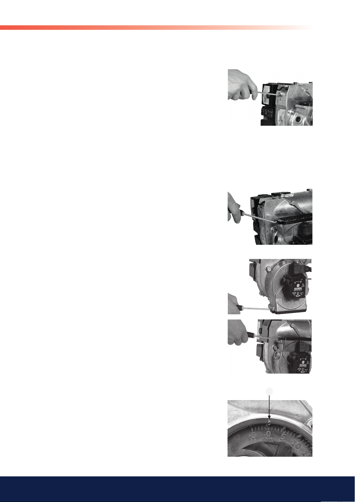
4.1.3 Nozzle assembly adjustment
The burner is fitted with a regulator which changes the brake plate position
in the blast tube. This is used to set the correct pressure drop across the
combustion assembly and thereby achieve good combustion without
pulsation.
The setting to be chosen is dependent among other things on set output
and furnace pressure.
Brake plate setting
• Less diffusion: turn screw to left.
• More diffusion: turn to right.
Setting brake plate position affects air flow. It is therefore always
necessary to adjust the air with the burner air regulator afterwards.
General
4.1.4 Air intake adjustment
Air settings are very important for achieving good combustion with neither
too much, nor too little, air. Adjustment of combustion airflow is carried out
by turning the air regulator with an Allen key. How far open the air regulator
must be is determined by output, furnace pressure and other burner settings
such as blast tube position.
4.1.5 Method of adjusting air quantity
Setting the air regulator is dependent on how the screw (with which air
regulation is adjusted) is installed. If the air intake is installed underneath
as shown in illustration Ι, turning the screw clockwise will reduce airflow,
and anticlockwise increase it. If the air intake is installed on top as shown
in illustration Π, clockwise adjustment increases airflow, and anticlockwise
reduces it.
Ι
Π
4.1.6 Inlet cone, air adjustment
Airflow is also affected by the position of the inlet cone. However, it is
extremely rare that this needs to be adjusted; it should be left in the
standard STD position to achieve good starts and operations. (A cast-in
arrow on the fan housing indicates the position of the inlet cone. In addition
to the scale on the inlet cone casting, there is also a mark (M) indicating the
factory setting.)
M
15 Bentone BF1
Page 16

General
4.1.7 Air intake rotation
It is possible to rotate the air intake to adapt the burner to different
surroundings. It is possible to rotate the air intake to a number of positions,
not just the positions shown to the right.
To rotate the air intake, undo the three screws that fasten the air intake and
the two screws which retain the pump. Then rotate the air intake to the
desired position and tighten the screws.The position of the air intake affects
the airflow through the burner somewhat.
The position which provides best airflow is with the air intake pointing
downwards.
4.1.8 Air duct
A hose connection air duct is available in three different dimensions: 48, 68,
and 78 mm outer diameter (D). The air duct is installed on the air intake at
the place where the grille is attached in the standard model
D
16
Bentone BF1
Page 17

5. BURNER SERVICING
5.1 Warning
Service must be carried out after 3,000 operating hours, or at least once per
year.
Only authorized personnel may perform service.
Before any type of service work is begun, switch of the power at the main
switch and shut off the oil.
Exercise caution as parts which are exposed when the burner is taken apart
can be hotter than 60°C. The installation engineer must be especially careful
to ensure that no electrical wiring or oil lines are pinched or damaged during
installation or service.
5.1.1 Service position
5.1.1.1 Service position 1
1. Switch off the power at the main switch and disconnect the Eurostecker
from the burner.
2. Undo the screw which fastens the burner front piece to the fan housing,
but only so much as to allow the fan housing to be removed from the
burner front piece.
3. Remove the fan housing from the burner front piece and pull it
backwards until the combustion assembly is free of the burner front
piece.
4. Suspend the fan housing by the fan housing attachment point (for
joining the front piece to the fan housing) on the screw (for joining the
front piece to the fan housing) as illustrated. If necessary, tighten the
screw somewhat to ensure that the burner is suspended safely.
General
!
Warning
5.1.1.2 Service position 2
1. Switch off the power at the main switch and disconnect the Eurostecker
from the burner.
2. Undo the screw which fastens the burner front piece to the fan housing,
but only so much as to allow the fan housing to be removed from the
burner front piece.
3. Remove the fan housing from the burner front piece and pull it
backwards until the combustion assembly is free of the burner front
piece.
4. Turn the screw into the front piece until there is a gap of approx. 5 mm
between the metal and the screw head.
5. Suspend the fan housing by the fan housing service attachment on
the screw used for joining the front piece to the fan housing, with the
motor upwards, as shown in the illustration.
When servicing or replacing components that affect combustion, analyses and soot tests must be carried
out on the installation.
!
17 Bentone BF1
Page 18

General
5.1.1.3 Service position 3
1. Switch off the power at the main switch and disconnect the Eurostecker
from the burner.
2. Undo the screw which fastens the burner front piece to the fan
housing, but only so much as to allow the fan housing to be removed
from the burner front piece.
3. Remove the fan housing from the burner front piece and pull it
backwards until the combustion assembly is free of the burner front
piece.
4. Turn the screw into the front piece until there is a gap of approx. 5 mm
between the metal and the screw head.
5. Suspend the fan housing by the fan housing service attachment on the
screw used for joining the front piece to the fan housing, with the air
intake upwards, as shown in the illustration.
5.1.2 Combustion assembly service
1. Switch off the power at the main switch and disconnect the Eurostecker
from the burner.
2. If so desired, service position 1 may be used.
3. Carry out a visual inspection of the combustion assembly and check
the various parts for defects.
4. Undo and remove the brake plate and the electrode package from the
oil pipe. Clean the brake plate as necessary.
5. Screw off the nozzle.
6. Install the nozzle. The nozzle may not be cleaned; it must be replaced
with a new nozzle if the existing one is considered defective.
7. Check the ignition electrodes. Replace as necessary (refer to Technical
data for electrode settings).
8. Install the brake plate and electrode package. Check that the distance
between the nozzle and brake plate is correct
(refer to Technical data).
9. Undo the screw that the fan housing is suspended from. Reassemble
the front piece and the fan housing and fasten them together.
10. Connect the Eurostecker and switch on the power at the main switch.
11. Start the burner and check the combustion.
18
When servicing or replacing components that affect combustion, analyses and soot tests must be carried
out on the installation.
!
Bentone BF1
Page 19

5.1.3 Preheater replacement
1. Switch off the power at the main switch and disconnect the Eurostecker
from the burner.
2. If so desired, service position 1 may be used.
3. Remove the brake plate and electrode package.
4. Disconnect the preheater cable from the preheater.
5. Screw off the nozzle.
6. Undo the nut that connects the oil pipe to the preheater.
7. Install the new preheater. Check the condition of the O-ring; replace
as necessary.
8. Connect the preheater cable.
9. Install the nozzle.
10. Install the brake plate and electrode package. Check that the distance
between the nozzle and brake plate is correct
(refer to Technical data).
11. Re-assemble the burner.
12. Connect the Eurostecker and switch on the power at the main switch.
13. Start the burner and check the combustion.
General
When servicing or replacing components that affect combustion, analyses and soot tests must be carried
out on the installation.
!
19 Bentone BF1
Page 20

General
5.1.4 Replacing the oil pump
1. Break the main current and disconnect the Euro plug from the burner.
2. Disconnect the electrical plug from the oil valve (1).
3. Detach the oil hoses from the pump.
4. Detach the solenoid valve housing from the valve (2). Remove the
entire solenoid valve housing.
5. Disconnect the oil connection pipes from the solenoid valve (3).
6. Loosen the screws (4) and pull out the oil pump and solenoid valve as
one assembly.
7. Turn the valve forward and detach it from the pump.
8. Reassemble in reverse order.
Do not forget thread
sealer between the
pump and the elbow.
!
(t.ex Loctite 5188,
5400)
1
2
4
3
fi g 1
20
When servicing or replacing components that affect combustion, analyses and soot tests must be carried
out on the installation.
!
Bentone BF1
Page 21

5.1.5 Fan motor replacement
1. Switch off the power at the main switch and disconnect the Eurostecker
from the burner.
2. If so desired, service position 2 may be used.
3. Remove the electrical connection from the motor.
4. Remove the electrical box retaining screw.
5. Remove the cable conduit entry to the ignition electrodes and the
preheater (where fitted) and remove the photocell cable from the motor
flange.
6. Undo the screws (H) to the motor flange, 5 pcs.
7. Lift away the motor.
8. Remove the drive coupling end from the motor shaft, loosen and
remove the fan wheel.
9. Install the fan wheel on the new motor, tighten the locking screw. The
fan wheel must be installed in the bottom position toward the motor
shaft. Install the drive coupling end.
10. Align and fit the motor flange to the fan housing. Pay attention to the
drive coupling so that it does not fall out, and also that it aligns
correctly in the drive coupling end of the motor and pump.
11. Bolt the motor flange and fan housing together. Tighten the screws
diagonally, and do not tighten hard one at a time. This is in order to
ensure the fan housing and the motor flange assume the correct
relative positions.
12. Place the cable conduit entry and the photocell cable in position.
13. Screw the electrical console in place.
14. Connect the motor wiring.
15. Join together the fan housing and the burner front piece.
16. Connect the Eurostecker and switch on the power at the main switch.
17. Start the burner and check the combustion.
General
H
When servicing or replacing components that affect combustion, analyses and soot tests must be carried
out on the installation.
!
21 Bentone BF1
Page 22

General
5.1.6 Air intake and intake cone service
1. Switch off the power at the main switch and disconnect the Eurostecker
from the burner.
2. If so desired, service position 3 may be used.
3. Remove the solenoid cable from the pump.
4. Remove the connecting pipe from the pump.
5. Undo the air intake retaining screws (I).
6. Remove the air intake.
7. Undo the inlet cone retaining screw; make note of the inlet cone
position.
8. Remove the inlet cone from the fan housing.
9. Check the function and visual condition of the various air regulator
components. Clean and replace components as necessary.
10. Re-assemble the burner. Be especially careful when installing the inlet
cone; install it in the same position it had at removal.
11. Fit the O-ring in the groove between the fan housing and inlet cone.
Ensure that it is properly located in the groove and is not damaged
when the air intake is fitted.
12. Connect the Eurostecker and switch on the power at the main switch.
13. Start the burner and check the combustion.
I
5.1.7 Fan wheel checks
5.1.7.1 Inspection
1. Switch off the power at the main switch and disconnect the Eurostecker
from the burner.
2. If so desired, service position 1 may be used.
3. Perform a visual inspection of the fan wheel. Spin the fan wheel with
your finger, or carefully using a tool.
4. If the fan wheel is not very dirty, clean it carefully where possible.
5. If thorough cleaning is required, refer to point 5.1.7.2 or alternatively
5.1.7.3.
6. If cleaning is not necessary, re-assemble the burner.
7. Connect the Eurostecker and switch on the power at the main switch.
8. Start the burner and check the combustion.
22
When servicing or replacing components that affect combustion, analyses and soot tests must be carried
out on the installation.
!
Bentone BF1
Page 23

5.1.7.2 Cleaning, alternative 1
1. Switch off the power at the main switch and disconnect the Eurostecker
from the burner.
2. If so desired, service position 3 may be used.
3. Remove the solenoid cable from the pump.
4. Remove the connector pipe from the pump.
5. Undo the air intake retaining screws (I).
6. Remove the air intake.
7. Undo the inlet cone retaining screw; make note of the inlet cone position.
8. Remove the inlet cone from the fan housing.
9. Clean the fan wheel. Undo and if necessary remove the fan wheel for
more thorough cleaning of the fan and fan housing.
10. Install the fan wheel; tighten the retaining screw. The fan wheel must
be installed in the bottom position toward the motor shaft. Install the
drive coupling end.
11. Re-assemble the burner. Pay attention to the drive coupling so that it
does not fall out, and also that it aligns correctly in the drive coupling
end of the motor and pump.
12. Fit the inlet cone in the same position as before disassembly
13. Fit the O-ring in the groove between the fan housing and inlet cone.
Ensure that it is properly located in the groove and is not damaged
when the air intake is fitted.
14. Connect the Eurostecker and switch on the power at the main switch.
15. Start the burner and check the combustion.
General
I
When servicing or replacing components that affect combustion, analyses and soot tests must be carried
out on the installation.
!
23 Bentone BF1
Page 24

General
5.1.7.3 Cleaning, alternative 2
1. Switch off the power at the main switch and disconnect the Eurostecker
from the burner.
2. If so desired, service position 2 may be used.
3. Remove the electrical connection from the motor.
4. Remove the electrical box retaining screw.
5. Remove the cable conduit entry to the ignition electrodes and the
preheater (where fitted) and remove the photocell cable from the
motor flange.
6. Undo the motor flange retaining screws (H), 5 pcs.
7. Lift away the motor.
8. Clean the fan wheel and the fan housing. For more thorough cleaning
remove the drive coupling from the motor shaft and loosen and remove
the fan wheel.
9. Install the fan wheel on the motor and tighten the locking screw. The
fan wheel must be installed in the bottom position toward the motor
shaft. Install the drive coupling end.
10. Align and fit the motor flange to the fan housing. Pay attention to the
drive coupling so that it does not fall out, and also that it aligns correctly
in the drive coupling end of the motor and pump.
11. Screw the motor flange and the fan housing together. Tighten the
screws diagonally, and do not tighten hard one at a time. This is in
order to ensure the fan housing and the motor flange assume the
correct relative positions.
12. Place the cable conduit entry and the photocell cable in position.
13. Screw the electrical box in place.
14. Connect the motor wiring.
15. Join together the fan housing and the burner front piece.
16. Connect the Eurostecker and switch on the power at the main switch.
17. Start the burner and check the combustion.
H
5.1.8 Electrical module
Check that the electrical console retaining screw is tight so that good
contact to earth is established between the console and the burner body.
Only use electrical components recommended by Enertech.
When servicing or replacing components that affect combustion, analyses and soot tests must be carried
out on the installation.
!
Bentone BF1
24
!
Warning
Page 25

5.1.8.1 Replacement of complete electrical package
1. Switch off the power at the main switch and disconnect the Eurostecker
from the burner.
2. If so desired, service position 2 may be used.
3. Remove the electrical connection from the motor.
4. Remove the electrical box retaining screw.
5. Remove the cable conduit entry to the ignition electrodes and the
preheater (where fitted) and remove the photocell cable from the
motor flange.
6. Install the new electrical package.
7. Place the cable conduit entry and the photocell cable in position.
8. Screw the electrical box in place.
9. Connect the motor wiring.
10. Assemble the fan housing and burner front piece.
11. Connect the Eurostecker and switch on the power at the main switch.
12. Start the burner and check the combustion.
General
5.1.8.2 Replacement of individual electrical components
1. Switch off the power at the main switch and disconnect the Eurostecker
from the burner.
2. If so desired, service position 2 may be used.
3. Remove the oil burner control.
4. Disconnect the wires to the components that are to be replaced.
5. Insert the new wires.
6. Install the oil burner control.
7. Assemble the fan housing and burner front piece.
8. Connect the Eurostecker and switch on the power at the main switch.
9. Start the burner and check the combustion.
When replacing the electrical components transformer and control box
included in the electrical package, the junction box lid need not be removed.
When servicing or replacing components that affect combustion, analyses and soot tests must be carried
out on the installation.
!
25 Bentone BF1
Page 26

General
6. PUMP INSTRUCTIONS
6.1 Suntec ANV47C
6.1.1 Technical data
Viscosity range: 2,0–75,0 mm2/s (cSt)
Pressure range: 7–14 bar
Oil temperature: max. 60°C
6.1.2 Components
1. Nozzle connection G 1/8”
2. Vacuum manometer connection G 1/8”
3. Manometer connection G 1/8”
4. Filter
5. Suction line G 1/4”
6. Metal plug G 1/4”
7. Return plug
8. Return line G 1/4”
9. Pressure regulation
26
Bentone BF1
Page 27

6.1.3 Filter replacement
Cut off the power and shut off the oil.
Remove the pump cover with the aid of a 4 mm Allen key. If necessary a
screwdriver may be used between the cover and the housing to carefully
pry the cover loose. Replace the old fi lter by a new one. Replace the cover,
tighten lightly.
Do not forget to replace the gasket.
Open the oil supply and switch on the power.
General
6.1.4 One-pipe system
Conversion to one-pipe system
Remove the return plug (8), plug the return
line (9) with the metal plug (7) G 1/4”.
6.1.5 Two-pipe system
Conversion to two-pipe system
Remove the metal plug (7) G ¼”, fi t the
return plug (8) in the return line (9).
Return plug are not included in products
with one-pipe system, separately sold.
6.1.6 Solenoid valve
9
8
7
5
6
1
32
4
27 Bentone BF1
Page 28

General
6.1.7 Function ANV47C
Pressure
adjustment
By-passed oil
returned to tank,
Back to
suction
Return
plugged
or to suction
By-pass plug
removed
One pipe
installation
Shaft seal
By-pass plug
inserted
Two pipe
installation
Gear set
Return Inlet
Pump working method
The oil pump is combined with an external solenoid valve that regulates oil
flow and providing a precise pressure within a large speed range.
The pump’s gear wheels draw oil from the tank through the integral filter
and conveys the oil to the regulator valve which pressurizes the nozzle
connection.
The quantity of oil that does not go to the nozzle connection is led through the
valve back to the return line, or in the case of a one-pipe installation, back to
the suction connection in the gear wheel pump.
To the nozzle
via external
solenoid valve
Pressure
gauge port
Oil under pressure
Vacuum
gauge port
Oil under suction
- Two-pipe system
When the solenoid valve is not activated, the return plug channel between the
pressure side and the return side of the pressure valve is open. No pressure
will be built up to open the pressure valve, regardless of gear wheel pump
rpm. When the solenoid valve is activated, the return plug channel is shut.
The gear wheel pump’s rotation at full rpm quickly builds up the pressure
necessary for opening the valve and provides a sharp opening action.
- One-pipe system
Purging of the oil line system is not automatic in the one-pipe system; open
the manometer connection for purging.
Shut-down
When the burner stops, the solenoid valve opens the return plug channel
and drains oil to the return line. At that same moment the nozzle line is
closed. This provides a sharp cut-off. The on and off functions can be
controlled independent of motor rpm, and react very quickly. When the
solenoid valve is not activated torque is low up to full motor rpm.
28
Bentone BF1
Page 29

6.1.8 Suction pipe tables ANV47C
6.1.8.1 Overhead Tank
One-pipe system
General
Height m
4,0 3,0 2,0 1,0 0,5 0,0
Line diameters
ø 4 mm 100 100 100 91 82 74
The table applies to Fuel oil 1Two-pipe system
Height m
4,0 3,0 2,0 1,0 0,5 0,0
Line diameters
ø 6 mm 29 25 22 18 16 14
The table applies to Fuel oil 1
6.1.8.2 Underlying Tank
One-pipe system
For reliable operations, use of a Tigerloop is recommended in underlying
tanks.
Two-pipe system
Height m
0,0 -0,5 -1,0 -2,0 -3,0 -4,0
Line diameters
ø 6 mm 14 12 10 7 3 0
H
H
The table applies to Fuel oil 1
The suction line tables comprise theoretically calculated values where
pipe dimensions and oil flow are adapted to prevent turbulent flows from
occurring.
Turbulent flows can result in pressure losses and noise in the pipework. A
typical pipe system usually comprises pipe runs with 4 bends, a non return
valve, a shut-off valve and a pre-filter.
The total resistance of these items is such that it can be disregarded. In the
tables no run longer than 100 m is listed, as experience shows this not to be
required.
The tables apply to standard heating oil of normal grade merchantable
according to existing norms. When starting operations with an empty pipe
system, the pump should not be run without oil for more than 5 min.
The tables give the total suction line length in meters with a nozzle
capacity of 2.1 kg/h. Max. permissible pressure on the suction and return
lines is 2.0 bar. For a two-pipe system the Q
46 l/h pump capacity at 0 bar
max
applies.
29 Bentone BF1
Page 30

General
7. PREHEATER
7.1.1 Function FPHE 5
When the boiler thermostat connects, the PTC element is energized and oil
begins to preheat. When the oil has reached the correct temperature, the
preheater thermostat closes and the burner receives the start signal.
During operations the PTC element compensates its output so that the
temperature does not become too high.
If the oil temperature is low and the oil flow high, the preheater thermostat
may open owing to the PTC element’s inability to maintain oil temperature. In
this case it is important to use oil burner controls with a preheater holding
circuit.
30
Bentone BF1
Page 31

8. ELECTRICAL EQUIPMENT
LMO1..2..4..
8.1 Wiring diagram
General
Alt. 1
According to DIN 4791
Alt 2 Alt 3 Alt 4
31 Bentone BF1
Page 32

General
8.1.1 Component list
A1 Oil burner control S3 Operations thermostat
E1 Preheater S4 Temperature limiter
F1 Fuse, max 10 A S7 Main switch
H1 Alarm lamp T1 Ignition transformer
M1 Burner motor Y1 Solenoid valve
P1 Timer (Accessory) X3 Plug-in contact, burner
R1 Photocell QRB X4 Plug-in contact, boiler
U2 UV-cell QRC
Preheater wiring colours: A Blue B Brown C Black
The installation must be connected to the mains and fused according to local
regulations.
8.1.2 Function LMO1..2..4..
1a. Operations switch ON, thermostat ON
The burner motor starts, ignition sparks initiated and pre-ventilation
continues until the set pre-ventilation period is over and the
solenoid valve (2) opens..
1b. Operations switch ON, thermostat ON
The preheater is energized and the pre-heating period begins.
This continues until the operating temperature is reached and the
preheater thermostat closes. The burner motor starts, ignition
sparks initiated and pre-ventilation continues until the set preventilation period is over and the solenoid valve (2) opens.
2. Solenoid valve opens
The oil mist is formed and ignited. The photocell indicates flame.
The ignition spark ceases 15 sec. after flame indication.
3.
Safety period runs out
a
If the flame is not present before the end of this period, the oil burner
control blocks further operation.
b
If the flame for any reason disappears after this time period, the
burner will make a new start attempt.
4-5 During operation
If burner operations are interrupted via the main switch or
thermostat, a new start will be initiated when conditions according
to point 1 are fulfilled.
Oil burner control blocks
Red light on the oil burner control illuminates. The burner is restarted by pressing the reset button.
32
Bentone BF1
Page 33

8.1.3 Technical data
LMO14 LMO24
Pre-ignition period:
Pre-ventilation period:
Post-ignition period:
Safety period:
Re-connection after release:
Reaction time flame extinction:
Ambient temperature:
Min. current with flame:
Max current when dark, start:
Ingress Protection:
LOA not to be used within EU
Photocell current checks
Photocell current is measured with a direct current ammeter
(mulitimeter A) connected in series with the photocell.
15 s 25 s
16 s 26 s
10 s 5 s
< 10 s < 5 s
< 1 s < 1 s
< 1 s < 1 s
-5 - +60°C -5 - +60°C
45 µA 45 µA
5,5 µA 5,5 µ A
IP 40 IP 40
General
33 Bentone BF1
Page 34

General
8.1.4 Colour codes LMO14/24
When the burner starts, three signal lights in the reset switch indicate the
normal sequence, as well as provide indication if something abnormal is
happening in accordance with the following table:
Preheater in operation Solid yellow
Ignition switched on Flashing yellow
Normal operation Solid green
Operation, poor flame signal Flashing green
Undervoltage Flashing yellow-red
Fault, alarm Solid red
False light Flashing red-green
Communication mode Fluttering red
8.1.5 Fault codes LMO14/24
When the red light for a blocked relay box comes on, you can get
information about what has caused the problem by pressing and holding the
reset button for 3 seconds.
The number of flashes below is repeated with a pause in between.
2 flashes No flame signal when safety time
expires
4 flashes False light during start
7 flashes 3 x Losses of flame during operation
8 flashes Time-out for preheater *
10 flashes Incorrect wiring, internal fault or
simultaneous occurrence of two faults
* In order for this fault code to occur, the preheater shall not reach its
cut-off temperature within 10 mins. from switch on.
To return to normal operation: Press the reset button for 1 second.
If the reset button is instead kept pressed a second time for at least 3
seconds, you can, via an interface, obtain the corresponding information on
a computer or flue gas analyser.
To return to normal operation: Press the reset button for 1 second
34
Bentone BF1
Page 35
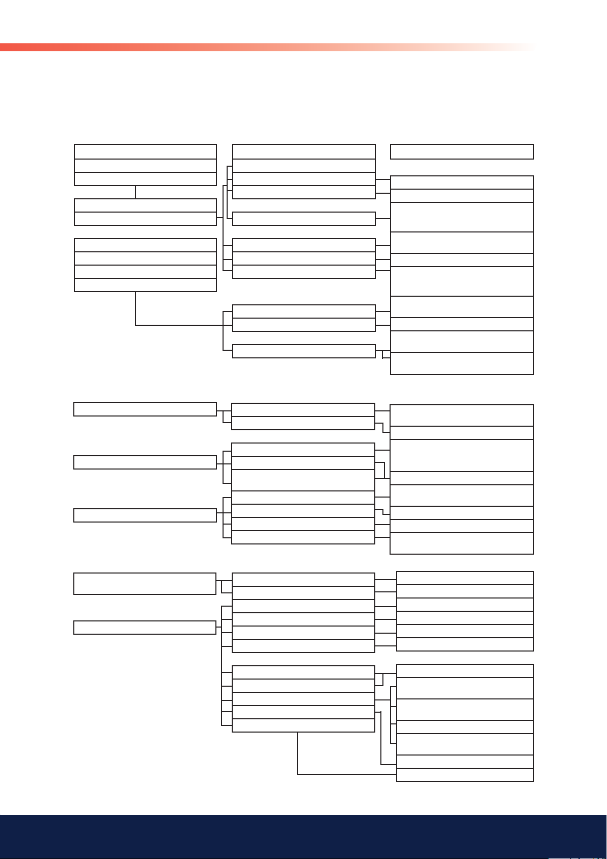
9. FAULT LOCATION
9.1 Burner will not start
Symptom
Motor starts
Burner pre-ventilates
Flame formed
Burner trips
Motor starts
Burner pre-ventilates
No flame formed
Burner trips
Incorrect combustion apparatus settings
Flame monitor doe s not register light
Causes
Unstable flame
Excess air
Low oil pressure
Defective flame monitor
Defective oil burner control
No oil
False light
No spark
General
Remedies
Adjust the damper
Check the oil pressure
Check the nozzle in relation to the
combustion apparatus dimensions and the
ignition electrode position
Check the flame monitor is clean and can
register light
Check with using new photocell
Check using new oil burner control (Note:
replacement of photocell recommended if oil
burner control replaced)
Check the oil supply to the burner and that
there are no air bubbles in the pump
Check function of solenoid
Check flame monitor does not register
ambient light
Check high voltage wiring and ignition
electrodes
9.2 Burner will not start after normal use
Burner does not start
Burner pre-ventilates
Burner stops
Overheating protection has deployed
Too great a pressure drop at brake plate
Too strong draught prevents flame forming
Fuse blown
Boiler thermostat has not reset
Defective preheater
Defective oil burner control or
flame monitor
No oil supply
No spark
Check that tank, oil lines, solenoid valves,
9.3 Delayed ignition, burner starts; pulsation
Burner pulsates at start with
hot flue gases
Burner pulsates at start
Too strong a draught
Too great a pressure drop at brake plate
Nozzle partially blocked
Oil pressure too low
Flue blocked or damaged
Fan wheel slipping on shaft
Pump coupling loose or worn
Preheater clogged
Delayed ignition
Too strong a draught
Too great a pressure drop at brake plate
Check and replace fuse as necessary.
Investigate cause of fault
Adjust thermostat
Reset the overheating protection.
Investigate the cause of its deploying.
Remedy fault
Check by replacing with new
pump and nozzle are in good condition
Adjust the burner
Correct the boiler draught
Check the ignition transformer. Check the
ignition electrode settings and ceramics
Correct the boiler draught
Adjust the burner
Replace nozzle
Check and adjust
Check and correct
Check and tighten
Replace
Check ignition electrode adjustment
(refer to technical data)
Check ignition electrodes
not damaged
Check high voltage wiring
Check position of nozzle
assembly adjustment
Correct the boiler draught
Adjust the burner
35 Bentone BF1
Page 36

10. DECLARATION OF
CONFORMITY
Page 37

11. OIL BURNERS MAINTENANCE
OIL BURNERS MAINTENANCE
INSTRUCTIONS
General information
Keep the boiler room clean. Ensure that the boiler
room has permanent fresh air intake. Switch off before
dismantling the oil burner.
At hinged mounting, make sure that an automatic safety
switch is fi tted, so that the burner cannot start when
theswing door is open.
Don´t use the oil fi red boiler to burn paper or
rubbish,unless the boiler is especially fi tted with a hinged
door tomake this possible.
Don´t fi ll tank while burner is working.
Starting precautions
Make sure that the oil tank is not empty
Make sure that the valves on oil and water supply pipes
areopen.
Make sure that the boiler fl ue damper is open.
Make sure that the boiler thermostat is set at the correct
temperature.
Switch on the current. Most relay systems have a
delayed action so that the burner will not start for
perhaps 20 seconds.
With heavy oil the delay will be longer as the burner
will notstart until the oil in the preheater reaches the
requiredtemperature.
If the burner will not start
INSTRUCTIONS
If the burner starts but does not ignite
Make an attempt to start the burner.
Never make close repeated start attempts.
Don´t restart the burner until the boiler is free from oil
gases.
If the burner still does not ignite send for the service
engineer.
When switching off during summer
Always use the main switch to cut out the burner even
when adjusting the burner or cutting off the heating for
ashort time. For longer periods of shut down, close all
valves and the oil supply stop-cock.
Clean the fi lter and nozzle by washing in petrol or
paraffi n.
Make sure the fi lter medium is not damaged or defective.
Protect electrical gear from damp.
Warning
Never stand too near or put your face to the inspection
or fi re door, when the burner is about to start.
Never use a naked fl ame to ignite oil if the electrical
ignition fails.
Always wait for about 10 minutes for the unburnt gases
to disperse before restarting the oil burner if it has failed
to ignite previously.
Press the reset button on the relay. Check that the
thermostats are correctly adjusted.
Don´t forget the room thermostat, check that any
fusesare intact and main switch is on.
Installed by:
Tel:
170 025 01 2012-04-16
Page 38

Page 39

Page 40

Enertech AB. P.O Box 309, SE-341 26 Ljungby.
www.bentone.se, www.bentone.com
 Loading...