

Page 1
Page 2

Digital Communicator Control Panel
Omnia 8/L
complies to:
Emission:
Immunity:
Low voltage:
Burglar alarm systems:
Terminal Equipment(TE):
EN 50081-1/1992
EN 50130-4/1995+A1/1999
EN 60950/1996 + A4/1997
CEI 79/2 2 Ed. 1993
TBR21-1/1993
a
BENTEL SECURITY declines all responsibility in the event of
unauthorized intervention on the control panel.
The control panel has been developed and made according to the highest
standards of quality, reliability and performance adopted by BENTEL
SECURITY srl.
To make sure your system continues to work as intended, you must test your
system every month. Consult the installer for testing and maintenance
instructions. If your system does not work correctly, call your installer for
service.
Installation of the control panel must carried out strictly according to the
instructions, and in compliance with the safety laws in force.
BENTEL SECURITY srl reserves the right to modify the technical specifications of this product
without prior notice.
via Florida - Z.I. Valtesino - 63013 GROTTAMMARE (AP) - ITALY
Main Unit Manual: Omnia 8/L Control Panel and Digital Communicator
Istruzioni Unità Centr. Ing. Bent. Omnia8L ISTUCBLEOMNIA8-L
Page 3

TABLE OF CONTENTS
PARTS 5
The Panel . . . . . . . . . . . . . . . . . . . . . . . . 5
INSTALLATION 6
Mounting the Panel . . . . . . . . . . . . . . . . . . . . 6
Terminal board . . . . . . . . . . . . . . . . . . . . . . . 6
Power supply connection . . . . . . . . . . . . . . . . . 8
Open Panel . . . . . . . . . . . . . . . . . . . . . . . . . 8
A Typical System . . . . . . . . . . . . . . . . . . . . . 9
NCDUEVOX voice board . . . . . . . . . . . . . . . . . . 12
3
Page 4
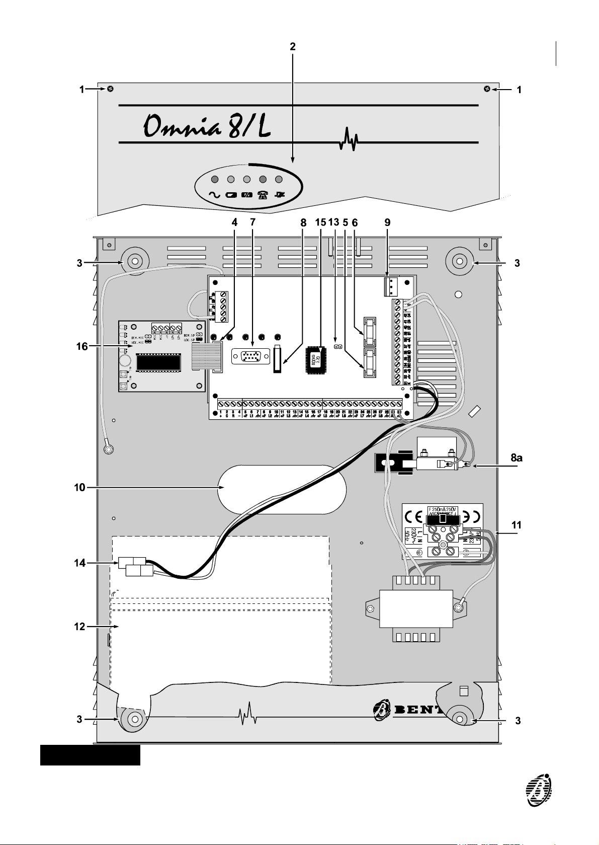
Figura 1 Omnia8/L Parts
4 Security System Control panel Omnia 8/L
P
Page 5

The table below provides a brief description of each part (the numbers in
boldface refer to the parts illustrated in the figure 1), and the meaning of
the ON / OFF status of each indicator LED.
The Panel
PARTS DESCRIPTIONS
1 4 screws
2 5 indicator LEDs
3 4 holes (Ø 5 mm)
4 NormVox2 voice board connector
5 Protection fuse for sensor and auxiliary power supply (250 V - 5 A)
6 Protection fuse against polarity inversion on battery (250 V - 8 A)
7 DB9 connector for PC connection via serial cable
PARTS
8-8a Tamper microswitch-8a (Optional)
Connector for the 3 A switching power supply BAQ35 or BAW35
9
(optional)
10 Cable hole
11
Mains connection terminals (230 V~ ∋10% / 150 mA)
12 Housing for 13.8 V / 7 Ah standby battery (optional)
Service mode jumper. Connection of this jumper will disable the Alarm
13
outputs for maintenance purposes.
14 Battery connectors
15 Firmware Release: to be communicated to Service dealer
16 NCDUEVOX voice board (optional)
LEDs STATUS
ON:
OFF:
OFF:
ON:
OFF:
ON:
Panel powered by mains
Mains failure ----Panel powered by battery
Battery OK
Battery low or battery trouble
Fuse 5 intact (power to sensors)
Fuse 5 blown
OFF:
ON:
OFF:
ON:
PARTS 5
Communicator in standby status: telephone line free
Telephone line engaged by the communicator
Communication OK
Communication bus trouble
Page 6

Mounting the Panel
The Panel should be located in a dry area, preferably near the power
source and incoming telephone line.
Follow the installation instructions carefully, and refer to figure 1.
Step 1 Unfasten the screws (1) and remove the front.
Step 2 Check for cable conduits and water pipes before drilling. Use the back box
as a drill pattern.
Step 3 Attach the NCDUEVOX voice board (if used).
Step 4 Pull the wires through the hole (10) and mount the back box.
INSTALLATION
Terminal board
Below is a description of the Panel terminal board, keypads and key readers.
Ø The Terminal column shows the terminal number and terminal identifier (in
square brackets).
Ø The DESCRIPTION column provides a description of each terminal.
The V column shows the voltage on the corresponding terminal.
The I column shows the maximum current for each terminal.
Where (1) or (2) is shown as the value in the I column----refer to the footnote below the table.
6 Security System Control panel Omnia 8/L
Page 7

Terminal DESCRIPTION V I
5-8-11-14
17-20-23-26 [+F]
6-9-12-15-18
21-24-27 [L1……L8]
7-10-13-16-19-22
25-28-30-32 [ ]
1 [+]
2 [C]
3 [R]
4 [-] Power supply (negative) (keypads and key readers)
29 [AS] Balanced Tamper line - -
38 [+A]
37 [+N]
Alarm Zones programmable as NC, NO, Balanced or
Connection terminal for standard BPI control devices
Connection terminal for standard BPI control devices
Sensor power-supply terminals 13.8 (1)
Double Balanced
Ground and Negative 0 -
Power supply to additional devices
(keypads and key readers)
(keypads and key readers)
(keypads and key readers)
Terminal for indoor sirens
Standby status è terminal open
Alarm status è voltage on terminal
Terminal for self-powered sirens
Standby status è voltage on terminal
Alarm status è terminal open
- -
13.8 (1)
- -
- -
13.8 (2)
13.8 (1)
34-35-36
[NC-COM-NO]
31 [K]
39-40-41-42
[O1] [O2] [O3] [O4]
33 [+B] Auxiliary power supply 13.8 (1)
45-46 [LE] Incoming Telephone Line connection terminals - -
47-48 [LI]
49 [ ]
(1) The total current absorbed by terminals [+F], [+B], [+] and [+N] must not
(2) Terminal [+A] can absorb up to 2.5 A for short periods.
Standby status è NC connected to COM and NO open
Alarm status è NO connected to COM and NC open
Auxiliary terminal to Arm / Disarm the Control panel by
(keylock switch, digital key, proximity key, etc.)
Programmable auxiliary open-collector output 0 0.5
exceed 1 A.
Voltage free alarm-relay contacts
means non-standard BPI devices
Terminals for line sharing devices
(switchboard, telephone, fax, modem, etc.)
Earth - -
- 3
13.8 -
- -
INSTALLATION 7
Page 8

Power supply connection
The Omnia8/L Panel is powered by the Mains source (230 V/50 Hz) through
an on-board power supply. The Mains wires must be connected to the terminals (11) and the battery must be connected to the connectors (14).
On power up----the green LED Main (on the Panel) will go ON.
The red LEDs:
Battery
Fuse
Communicator
Communication Bus----will all go OFF.
Open Panel
+
On power up (Panel Open)----the OPEN LED on the keypad will go ON but the
Panel will not generate a Tamper Alarm. However, once the Panel is closed
a Tamper Alarm will be generated if the Panel is reopened.
The battery (13.8 V, 7 Ah max. not supplied) will supply the power during
mains failure. Mains failure will be signalled as follows:
Ø The MAIN LED on the Panel will go OFF.
Ø The TROUBLE LED on the Control Keypad will go ON.
Ø Activation of one of the auxiliary outputs: 39[O1], 40[O2], 41[O3], 42[O4]----if
programmed to signal TROUBLE.
The cause of trouble must always be eliminated before the battery emp-
ties. Total power failure (mains and battery) will not affect the configuration,
as the non-volatile memory will save any changes made during Armed
status.
Access the programming phase before opening the Panel for servicing,
testing etc., as this will disable the tamper microswitch.
Step 1 Enter INSTALLER PIN.
Step 2
Step 3 Open the Panel.
Step 1 Enter MAIN USER PIN.
Step 2
Press to access programming.
or
Press .
8 Security System Control panel Omnia 8/L
Page 9

Step 3
Step 4 Open the Panel and service as required.
Step 5 Close the Panel.
Press to access programming.
The OPEN LED on the keypads will stay ON until the Panel is closed
again. No alarms will be generated during this phase.
Step 6
A Typical System
Ø Incoming telephone line connection
Ø Signalling device connections----indoor siren and self-powered siren
Ø Connection of a burglar sensor to line L1
Ø Connection of three fire sensors to line L8
Ø Connection of the Tamper line to the siren
Ø Connection of additional devices (Keypad and Key reader) to the BPI bus
Ø Line L1 must be programmed as Double Balanced. This configuration
Ø Line L8 must be programmed as Fire, and the auxiliary output (terminal
Press to exit the programming phase.
Figure 2 illustrates a typical system.
Please note:
provides tamper detection, and requires 2 wires only.
42[O4]) as Fire GND ---- Normally Closed.
+
Not all Alarm line connections are illustrated, however, burglar sensors
must be connected as per line L1, and fire sensors as per line L8.
Use shielded cable----one end must be connected to the Panel ground and
the other to the device ground.
INSTALLATION 9
Page 10

Figure 2 A Typical System
Page 11

INSTALLATION 11
Page 12

NCDUEVOX voice board
How to attach the board
Disconnect the Mains and battery before attaching the NCDUEVOX board
to a Panel that is in service.
Attach the NCDUEVOX board as follows (see also figure 3).
Step 1 Remove the strip of paper from the self-adhesive gasket (47) and position
the gasket in the centre of the four holes on the back box, as per figure 3.
Step 2 Slot the NCDUEVOX voice board into its holder----microphone to the top.
Step 3 Connect the NCDUEVOX cable (40) to the connector (4) on the Panel board.
Step 4 When the NCDUEVOX board is properly attached----complete the connec-
tions then power the Panel, and record the alarm messages, as per the instructions in the INSTALLATION MANUAL.
The optional OmniaVox-MS and Speaker will allow Remote Listen-in on
ambients, other than that of the Panel. Locate the OmniaVox-MS and
Speaker as required then complete the connections with the Voice Board
(use shielded cable only). Refer to the Installation Manual.
40
4
47
Figure 3 Attaching the NCDUEVOX board
ISTUCBLEOMNIA8-L 1.1 260601 V4.2 BUUC
 Loading...