

KYO
Unit
MADE
IN
ITALY
MAIN UNIT
MANUAL
®
®®
KYO 4 M – KYO 8 M – KYO 32 M – KYO 4 P – KYO 8 P – KYO 32 P
KYO 8G P-SW1 – KYO 8G P-SW2 – KYO 32G P-SW1 – KYO 32G P-SW2
Hereby, Bentel Security, declares that the above mentioned Control Panels are in compliance with the essential
requirements and other relevant provisions of Directive 1999/5/EC.
The complete R&TTE Declaration of Conformity for each Panel can be found at
These Control Panels comply with CEI 79-2 2
Installation of these systems must be carried out strictly in accordance with the instructions
described in this manual, and in compliance with the local laws and bylaws in force.
The above mentioned Control panels have been designed and made
The manufacturer recommends that the installed system should be completely tested at least once a month.
BENTEL SECURITY Srl shall not assume the responsibility
The above mentioned Control panels have no user-friendly components, therefore,
www.bentelsecurity.com/dc.html.
a
ed. 1993.
to the highest standards of quality and performance.
for damage arising from improper application or use.
should be serviced by authorized personnel only.
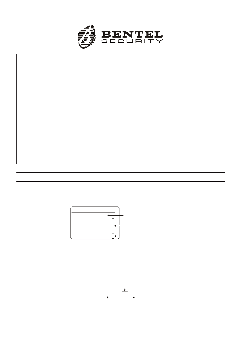
IMPORTANT: The following information is for disassembled Control Panels ONLY.
Ensure that the Manual you are using corresponds to that requested on the “RELEASE
ISSUES” label (see below) inside the package. Upgrades of the required KYO Unit Soft-
ware Release are also suitable.
RELEASE ISSUES
OK32 1.00 EN
Installation Manual
User Manual
Keypad Prog. Man.
Main Unit Manual
Kyo Unit Software
1.1
1.1
1.1
1.1
5.10
Firmware Release
Manual Release
Software Release
If the Manual/KYO Unit Software release does not correspond, DO NOT attempt to assemble or install the Control Panel until you have the required release.
The Manual Release Number is shown at the bottom of the last page, between the Code
and Date, and indicated in the figure below.
Manual
Release
Number
ISTUCBLEUNKYO 190303 P70
BENTEL SECURITY srl reserves the right to modify the technical specifications of this product without prior notice.
1.1
DateCode

®®
TABLE OF CONTENTS
Section 1 - Introduction .................................................. 5
Certification Formalities .................................................................... 5
General Features ................................................................................ 5
About the System ............................................................................... 7
Control panel Versions ...................................................................... 7
Components and Accessories .......................................................... 8
Technical Specifications ................................................................... 9
Section 2 - Identification of Components .................... 10
KYO 4 M – KYO 8 M – KYO 32 M ...................................................... 10
KYO 4 P – KYO 8 P – KYO 32 P ........................................................ 11
KYO 8G P-SW1 – KYO 32G P-SW1 .................................................. 12
KYO 8G P-SW2 – KYO 32G P-SW2 .................................................. 13
Status LEDs (only for ‘G’ series PCBs) ........................................... 1 5
Section 3 - Mounting the Components ....................... 17
Introduction ....................................................................................... 17
Boxes and Accessories .................................................................. 17
Installing the Transformer and Mains Screw Terminal - Fused... 18
Metal box ........................................................................... 18
Plastic box ........................................................................ 19
Mounting K4-K8-K32 PCBs .............................................................. 19
Installing ‘G’ series PCBs (K8G-K32G) ............................................ 20
Metal box ........................................................................... 20
Plastic box ........................................................................ 20
Installing the Switching Power Supply ........................................... 21
Installing BAQ15 Switching Power Supplies .................. 21
Installing BAQ35T12 Switching Power Supplies ............ 21
Earthing the PCB ............................................................................... 22
Marking Ticket .................................................................................. 22
Connecting the KST Thermal Probe ............................................... 22
Connecting the NC2/VOX Voice Board............................................ 23
Metal box ........................................................................... 23
Plastic box ........................................................................ 24
PCB Identification Label ................................................................... 24
3

4
Multifunction Control Panel
Section 4 - Installing the Control Panel ....................... 25
Mounting the Control Panel ............................................................. 25
Opening and Closing the Control Panel .......................................... 26
Section 5 - Installing the NC2/VOX .............................. 28
General Features .............................................................................. 28
Additional VOX-REM Modules .......................................................... 28
Installing Additional VOX-REM Modules .......................... 28
Record / Play Messages .................................................................. 29
Selecting Messages ........................................................ 30
Recording Alarm Messages ............................................ 30
Playing Messages ............................................................ 30
Programming .................................................................................... 31
Activation .......................................................................................... 31
®®

®®
Certification Formalities
The KYO-Unit series can be purchased as out-of-the-box Control panels, or as separate package components. Bentel Security S.r.l declares
that KYO-Unit separate package components comply with the essential requirements and other relevant provisions of Directive R&TTE
1999/5/CE — only when they are assembled by a security professional,
and are used as part of one of the Control panels provided for in
Section 3, and indicated in Table 1.1. in this Manual. Bentel Security S.r.l. declares that CE Certification is not applicable when KYO
separate package components are improperly assembled or used.
General Features
This Manual is designed for anyone using a Control panel from the KYO range.
Most of the features described in this Manual are included on all KYO Control
panels (refer to Table 1.1). However, some features are included on certain
models only, in such cases, the Control panel will be specified.
Section 1 - Introduction
SECTION 1 - INTRODUCTION
5
Control Panel
Version
KYO 4 M K4 BOX-M
KYO 8 M K8 BOX-M
KYO 32 M K32 BOX-M
KYO 4 P K4 BOX-P
KYO 8 P K8 BOX-P
KYO 32 P K32 BO X-P
KYO 8G P-SW1 K8G BO X-P
KYO 32G P-SW1 K32G BOX-P
KYO 8G P-SW2 K8G BOX-P
KYO 32G P-SW2 K32G BO X-P
8 Programmable Input Zones (4 for KYO 4 M and KYO 4 P)
Expandable to 32 Input Zones via optional M-IN/6 Input Expanders (for
KYO 32 series Control panels)
1 Balanced 24h Tamper Zone
1 Programmable Alarm Output: 1A relay (3A on ‘G’ models)
Auxiliary Open-Collector Outputs (OC):
3 x 150 mA for KYO 4, KYO 8 and KYO 32 series
5 x 500 mA for KYO 8 G and KYO 32 G series
Table 1.1 - Version
PCB Box Transf. TRF
Component
Power Supply
BAQ15
Power Supply
BAQ35T12

6
Digital Dialler
Multifunction Control Panel
Expandable to 14 x 150 mA Outputs for KYO 32 series
Expandable to 16 x 150 mA Outputs for KYO 32 G series
Metal box (Model M) or Plastic Box (Model P)
Accepts Conventional Fire Detectors, and provides restoral facility
Supports up to 8 Keypads
Supports up to 16 Readers (ECLIPSE and/or PROXI)
Accepts up to 128 SAT Keys and/or PROXI-CARDs
Manages 4 independent Partitions (8 for KYO 32 and KYO 32 G)
3 Arming Modes (Global, A Mode and B Mode): A and B Mode can be
programmed as: Away, Stay or Stay with no Entry delay
Auto-Arming for each Partition on Daily or Weekly basis
24 Programmable Codes (4 to 6 digits)
Partition Bypass for Patrol purposes with automatic or manual Rearming
Can be programmed from LCD Keypads (MIA or OMNIA/TAST-R)
Can be programmed from a computer via RS232 link cable or via telephone
Power Supplies:
Integrated 1A linear Power Supply in KYO 4, KYO 8 and KYO 32
1.5A Switching Power Supply in KYO 8G P-SW1 and KYO 32G P-SW1
3A Switching Power Supply in KYO 8G P-SW2 and KYO 32G P-SW2
Touch-tone (MF) or Pulse dialling
Manages 8 Telephone numbers for Alarm and Central Station calls
Supports the following Reporting Formats:
ADEMCO / SILENT KNIGHT - Slow 10 baud - 3/1, 4/1, 4/2
ADEMCO / SILENT KNIGHT - Fast 14 baud - 3/1, 4/1, 4/2
FRANKLIN / SECOA / DCI-VERTEX - Fast 20 baud - 3/1, 4/1, 4/2
RADIONICS - 40 baud - 3/1, 4/1, 4/2
SCANTRONIC - 10 baud - 3/1, 4/1, 4/2
CONTACT ID
CESA
Accepts commands from touch-tone phones (Arm, Disarm, Turn ON/OFF
Main board Outputs; Remote Talk/Listen-in — requires optional NC2/
VOX Voice Board
Manages Voice Calls (requires optional NC2/VOX Voice Board)
Remote Telephone Access via Dialler or Answer Mode
Remote Talk/Listen-in (requires optional NC2/VOX Voice Board)
256 Event Logger (can be viewed on computer or LCD Keypad) on Series
32 Models. 128 Events on Series 4-8 Models.
3 function keys for immediate Alarm calls from Keypad
Programmable Test Call
Teleservice Management
Double Call
Line-sharing Management
®®
®®
About the System
Section 1 - Introduction
7
The Control panel
The Digital Communi-
cator
Voice Messages using
NC2/VOX
Teleservice
Telemonitoring
Accessing the system
using a remote Touch-
tone Telephone
Programming the
system
The Control panel is made up of a Control Unit, Digital Communicator and
Modem. It can be controlled from remote Keypads and/or Digital Key/Card
Readers.
The Digital Communicator can call up to 8 Telephone numbers for Teleservice
and communication to Central Stations. You can program the system to report
events using any one of the supported formats.
The NC2/VOX Voice board (accessory item) will allow the Communicator to
send 8 Voice messages to up to 8 Telephone numbers. The NC2/VOX Voice
board also provides the Talk/Listen-in feature.
The B-MOD Modem and Management software will allow you to program,
control and Teleservice (provide remote maintenance) from a remote computer.
The B-MOD/Rx Modem and the WinBCS software will allow you to program,
control, Teleservice and Monitor the system from a remote computer.
All Events, Alarms and Troubles, complete with Customer and Event details will
be logged on the Event Logger.
The User can access the system over the phone, in order to:
Arm/Disarm the system
Turn ON/OFF Reserved Outputs
Activate Talk/Listen-in sessions (NC2/VOX required)
This Control panel can be programmed:
a) on-site, using a MIA or OMNIA/TAST-R Keypad (accessory item)
b) on-site, using an RS232 Computer link
c) from remote computer, using a modem and downloading software
Control panel Versions
Table 1.2 - Functional differences between Models
Model
KYO 4 M
KYO 8 M
KYO 32 M
KYO 8G P-SW1
KYO 32G P-SW1
** The
M-IN/6 Expander Module manages 6 Inputs
**
The M-OUT/6 Expander Module manages 6 OC Outputs — 150 mA (6 x 150 mA)
KYO 4 P 4 4 3 x 150 mA
KYO 8 P 4 8 3 x 150 mA
KYO 32 P 8
KYO 8G P-SW2 4 8 5 x 500 mA
KYO 32G P-SW2 8
Partition Innput (Zone ) O.C. Output
Features
Expandable to 32*
Expandable to 32*
8
8
3 x 150 mA
Expandable to 14 **
5 x 500 mA
Expandable to 16 **

8
Multifunction Control Panel
Components and Accessories
Table 1.3 - Components and Accessory Items
Code Description
K4 - K8 - K32 PCB for KYO4, KYO8 and KYO32
K8G - K32G PCB for KYO8 G an d KY O 32 G
BOX-M Metal box for M Models
BOX-P Pl astic box for P Models
TRF 17 Vac - 1.5 A Power Transformer
BAQ 15 1.5 A Switching Power Supply for SW1 Models
BAQ 35 T12 3 A Switching Power Supply for SW2 Models
MIA-D LCD Keypad (can be used fo r program m ing)
MIA-S LCD Keypad (can b e used for progr amming)
OMNIA/TAST-R LCD Keypad (can be used for program ming)
NC2/T AST LED keypad
ICO N/KP LED keypad
ECLIPSE Flush Mount Contactless Key Reader
PROXI Proximity Reader
SAT Digital key for ECLIPSE and PROXI Readers
PROXI-CARD PROXI Card
NC2/VOX Voi ce Board
VOX-REM Talk/Listen-In Zone Expander Module (Microphone + Loudspeaker)
M-IN/6 6 Input Expander Module
M-OUT/6 6 Output Expander Module (150 mA)
KISUNIT Manual Kit
VECTOR/RX
ARC10 Wireless Key for Vector/RX
AMD10 Wireless Pet Immune PIR for Vector/RX
AMC10 Wireless Magnetic Contact for Vector/RX
ASD10 Wirel ess Smo ke Detector for Vector/RX
AGD10 Wireless Glassbreak Detector for Vector/RX
B-MOD Teles ervi c e Mo d e m
B-MOD/RX Teleservice and Telemonitoring Modem
SECURITY SUITE Management Software
CVSER/9F9F Computer Serial Link
ADSER/9M25F Adapter for CVSER/9F9F link cable for 25 Pole Serial Ports (DB-25)
KST Therm al P robe (for G Models only)
OVC-Link Output Voltage Control wire (for G Models only)
ASNC Snatch Mi croswitch for MIA Keypads and Tamper for Pl astic boxes
MINI-ASNC Sn atch Microswitch for PROXI-REA DERs
MAXI-ASNC Tamper Micro switch fo r Metal boxes
Wireless Receiver — manages 16 Wireless devices
(e.g. ARC10, AMD10, AMC10, AGB10, ASD10)
®®

®®
Section 1 - Introduction
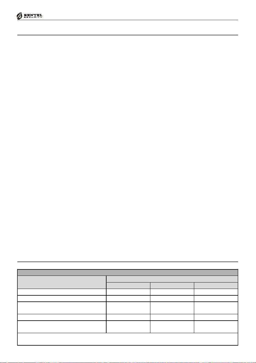
Technical Specifications
Table 1.4 shows the Technical Specifications of the various Control panels and
accessory items.
Table 1.4 - Technical Specifications
Control Panels
Values
Specifications
KYO 4 M
KYO 8 M
KYO 32 M
Voltage 230V
Maximum Current draw 0.2 A 0.21 A 0.5 A
Maximum Power 45 W 50 W 115 W
Power Supply Battery-charger 13.8 V
Insulation Class I
Maximum Current available for
peripherals
(including the battery charge
current)
Battery Housing
(Brand and Type)
Recognized MF Tones
Minimum Level 200 mVpp (-23 dBV) for Kyo32 Series
Minimum Level 360 mVpp (-17 dBV) for Kyo4-8 Series
Operating Temperature +5 ÷ +40º C
Dimensions in mm (W x H x D) 235 x 269 x 77 309 x 227 x 89
Weight (without Battery) 2.7 Kg 1.8 Kg 1.2 Kg 1.3 Kg
Complies with
CEI Normative Laws
EN50130-4:1995+A 1:1998 - CEI 79-2 2
KYO 4 P
KYO 8 P
KYO 32 P
_ / 1 A 13.8 V_ / 1.5 A 13.8 V_ / 3 A
KYO 8 G P-SW1
KYO 32 G P-SW1
~ 50Hz ±10%
KYO 8 G P-SW2
KYO 32 G P-SW2
0.9 A 1.3 A 2.8 A
12V - 7Ah
YUASA NP7-12 FR or Equivalent with
UL94-V2 (or superior) Case Flame Class
EN 60950:2000 - EN50081-1:1992
a
ed. 1993
9
COMPONENTS and ACCESSORY ITEMS
Description Max. Current Draw (mA) Dimensions (W x H x D) mm
Main Board
KYO 4-8-32 100 122 x 118
KYO 8G-32G 150 166 x 109
MIA-S / MIA-D 50 164 x 133 x 44
Keypad
OMNIA/TAST-R 50 160 x 73 x 30
NC2/TAST 80 117 x 96 x 25
ICON/KP 80 160 x 73 x 30
Reader
Expander
ECLIPSE 30 20 x 44 x 48
PROXI 30 78 x 108 x 22
M-IN/6 (Input) 27 108 x 101 x 34
M-OUT/6 (Output) 11 108 x 101 x 34
NC2/VOX Voice Board 30 58 x 71
VectorRX Receiver 50 146 x 290 x 28

10
Multifunction Control Panel
SECTION 2 - IDENTIFICATION OF COMPONENTS
The numbers in boldface in square brackets [ ], in this and other Manuals
relevant to this product, refer to the components described in this section.
®®
KYO 4 M
11b
3a
13c
3a
12a
3a
17
15
KYO 8 M
KYO 32 M
1
11d 9d
LE LI
3332 34 35 36
56
11d
2 2
4
7
8 9a
10
31
AC
30
REDBLKYEL
27 2928
GRN
03
25 26
COMNC 0201+B
19 20 2221 2423
4
1
3a
4
9c
10
3a
19c
19b
19a
13a
18
2
14
2
Figure 2.1 - KYO 32 M Control panel complete with NC2/VOX Voice Board (accessory item)
 Loading...