


KYO
Unit
MADE
IN
ITALY
MAIN UNIT
MANUAL
®

®®
KYO 4 M – KYO 8 M – KYO 8W M – KYO 32 M – KYO 4 P – KYO 8 P – KYO 8W P – KYO 32 P
KYO 8GWP-SW1 – KYO 8GWP-SW2 – KYO 8GWL-SW1 – KYO 8GWL-SW2
KYO 8G P-SW1 – KYO 8G P-SW2 – KYO 32G P-SW1 – KYO 32G P-SW2
KYO 8G L-SW1 – KYO 8G L-SW2 – KYO 32G L-SW1 – KYO 32G L-SW2
Hereby, Bentel Security, declares the above mentioned Control Panels to be in compliance with the
The manufacturer recommends that the installed system should be completely tested at least once a month.
essential requirements and other relevant provisions of 1999/5/EC Directive.
The complete R&TTE Declaration of Conformity for each Panel can be found at
These Control Panels comply with
Installation of these systems must be carried out strictly in accordance with the instructions
described in this manual, and in compliance with the local laws and bylaws in force.
The above mentioned Control panels have been designed and made
BENTEL SECURITY Srl shall not assume the responsibility
The above mentioned Control panels have no user-friendly components, therefore,
www.bentelsecurity.com/dc.html.
CEI 79-2 2 ed. 1993
to the highest standards of quality and performance.
for damage arising from improper applicati on or use.
should be serviced by authorized personnel only.
a
.
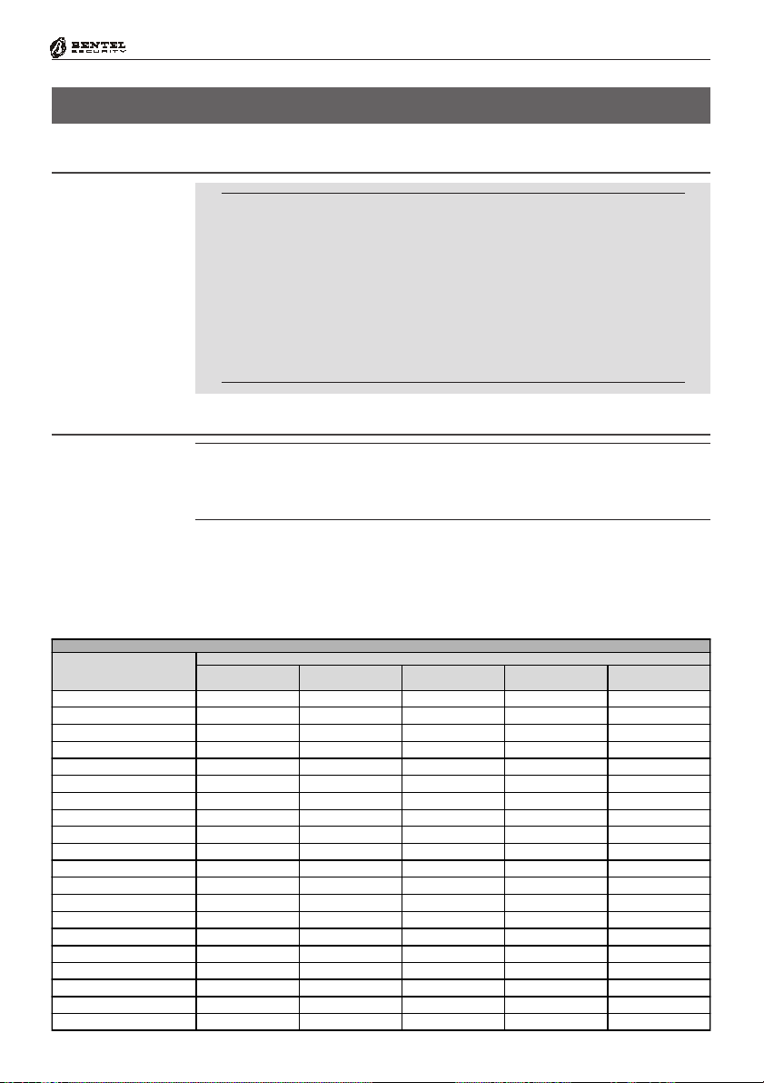
IMPORTANT: The following information is for disassembled Control Panels ONLY.
Ensure that the Manual you are using corresponds to, or is higher than the one requested
on the “RELEASE ISSUES” label (see below).
RELEASE ISSUES
OK32 1.01
Installation Manual
User Manual
Keypad Prog. Man.
Main Unit Manual
Kyo Unit Software
1.1
1.1
1.1
1.1
5.10
Firmware Release
Manual Release
Software Release
If the Manual/KYO Unit Software release does not correspond, DO NOT attempt to assemble or install the Control Panel.
The Manual Release Number can be found at the bottom of the last page, between the
Code and Date, as shown in the Fig. below.
Manual
Release
Number
ISTUCBLEUNKYO 190503 P70
BENTEL SECURITY srl reserves the right to modify the technical specifications of this product without prior notice.
1.2
DateCode

®®
TABLE OF CONTENTS
Section 1 - Introduction .............................................................5
Certification Formalities ......................................................................................... 5
General Features..................................................................................................... 5
About the System .................................................................................................... 7
Control panel Versions ........................................................................................... 7
Components and Accessories .............................................................................. 8
Technical Specifications ........................................................................................ 9
Section 2 - Identification of Components .............................. 10
KYO 4 M — KYO 8 M — KYO 8W M — KYO 32 M ................................................. 10
KYO 4 P — KYO 8 P — KYO 8W P — KYO 32 P .................................................... 11
KYO 8G P-SW1 — KYO 8GWP-SW1 — KYO 32G P-SW1..................................... 12
KYO 8G P-SW2 — KYO 8GWP-SW2 — KYO 32G P-SW2..................................... 13
KYO 8G L-SW1 — KYO 8GWL-SW1 — KYO 32G L-SW1 ..................................... 14
KYO 8G L-SW2 — KYO 8GWL-SW2 — KYO 32G L-SW2 ..................................... 15
Section 3 - Mounting the Components .................................. 19
Introduction ........................................................................................................... 19
Boxes and Accessories ....................................................................................... 19
Installing the Transformer and Mains Screw Terminal - Fused ......................... 20
Metal box (BOX-M) ............................................................................................ 20
Plastic box (BOX-P) .......................................................................................... 21
Mounting K4-K8-K8W-K32 PCBs .......................................................................... 22
Metal box (BOX-M) ............................................................................................ 22
Plastic box (BOX-P) .......................................................................................... 22
Installing ‘G’ series PCBs (K8G-K8GW-K32G) ..................................................... 23
Plastic box (BOX-P) .......................................................................................... 23
Metal box BOX-L ............................................................................................... 23
Installing the Switching Power Supply ................................................................ 24
Installing BAQ15T12 Switching Power Supplies ............................................. 24
Installing BAQ35T12 Switching Power Supplies ............................................. 25
Replacing BAQ35T12 Fuse ............................................................................. 25
Earthing the PCB ................................................................................................... 26
Marking Ticket ....................................................................................................... 26
Connecting the KST Thermal Probe .................................................................... 26
Connecting the NC2/VOX Voice Board ................................................................. 27
Metal box ........................................................................................................... 27
Plastic box ........................................................................................................ 27
PCB Identification Label ....................................................................................... 28
3

4
Multifunction Control Panel
Section 4 - Installing the Control Panel ................................. 29
Mounting the Control Panel .................................................................................. 29
Opening and Closing the Control Panel ............................................................... 30
Section 5 - Installing the NC2/VOX......................................... 32
General Features................................................................................................... 32
Additional VOX-REM Modules............................................................................... 32
Installing Additional VOX-REM Modules .......................................................... 32
Record / Play Messages ....................................................................................... 33
Selecting Messages ........................................................................................ 34
Recording Alarm Messages ............................................................................ 34
Playing Messages ............................................................................................ 34
Programming ........................................................................................................ 35
Activation ............................................................................................................... 35
®®
®®
SECTION 1 - INTRODUCTION
Certification Formalities
The KYO-Unit series can be purchased as out-of-the-box Control panels, or as separate package components. Bentel Security S.r.l declares
that KYO-Unit separate package components comply with the essential requirements and other relevant provisions of Directive R&TTE
1999/5/CE — only when they are assembled by a security professional,
and are used as part of one of the Control panels provided for in
Section 3, and indicated in Table 1.1. in this Manual. Bentel Security S.r.l. declares that CE Certification is not applicable when KYO
separate package components are improperly assembled or used.
General Features
This Manual is designed for anyone using a Control panel from the KYO range.
Most of the features described in this Manual are included on all KYO Control
panels (refer to Table 1.1). However, some features are included on certain
models only, in such cases, the Control panel will be specified.
Section 1 - Introduction
5
Control Panel
8 Programmable Input Zones (4 for KYO 4 M and KYO 4 P)
Expandable to 32 Input Zones via optional M-IN/6 Input Expanders (for
KYO 32 series Control panels)
1 Balanced 24h Tamper Zone
1 Programmable Alarm Output: 1A relay (3A on ‘G’ models)
Table 1.1 - Version
Version
KYO 4 M K4 BO X-M
KYO 8 M K8 BO X-M
KYO 8W M K8W BO X-M
KYO 32 M K32 BO X-M
KYO 4 P K4 BO X-P
KYO 8 P K8 BO X-P
KYO 8W P K8 W BO X-P
KYO 32 P K3 2 BO X-P
KYO 8G P-SW1 K8G BO X-P
KYO 8GWP-SW1 K8G W BO X-P
KYO 32G P-SW 1 K32G BOX-P
KYO 8G P-SW2 K8G BO X-P
KYO 8GW P-SW2 K8G W BO X-P
KYO 32G P-SW 2 K3 2G BO X-P
KYO 8G L-SW1 K8G BO X-L
KYO 8GW L-SW1 K8 G W BO X-L
KYO 32G L-SW1 K32G BO X-L
KYO 8G L-SW2 K8 G BO X -L
KYO 8GW L-SW2 K8G W BO X-L
KYO 32G L-SW2 K32 G BO X-L
PCB Box Transf. TRF
Component
Power Supply
BAQ15T12
Power Supply
BAQ 35T12

6
Digital Dialler
Multifunction Control Panel
Auxiliary Open-Collector Outputs (OC):
3 x 150 mA for KYO 4, KYO 8, KYO 8W and KYO 32 series
5 x 500 mA for KYO 8 G, KYO 8 GW and KYO 32 G series
Expandable to 14 x 150 mA Outputs for KYO 32 series
Expandable to 16 x 150 mA Outputs for KYO 32 G series
Metal box (Model M or L) or Plastic Box (Model P)
Accepts Conventional Fire Detectors, and provides restoral facility
Supports up to 8 Keypads
Supports up to 16 Readers (ECLIPSE and/or PROXI)
Accepts up to 128 SAT Keys and/or PROXI-CARDs
Manages 4 independent Partitions (8 for KYO 32 and KYO 32 G)
3 Arming Modes (Global, A Mode and B Mode): A and B Mode can be
programmed as: Away, Stay or Stay with no Entry delay
Auto-Arming for each Partition on Daily or Weekly basis
24 Programmable Codes (4 to 6 digits)
Partition Bypass for Patrol purposes with automatic or manual Rearming
Can be programmed from an LCD or LED Keypad
Can be programmed from a computer via RS232 link cable or via telephone
Power Supplies:
Integrated 1A linear Power Supply in KYO 4, KYO 8, KYO 8W and KYO 32
1.5A Switching Power Supply in SW1 Models
3A Switching Power Supply in SW2 Models
Touch-tone (MF) or Pulse dialling
Manages 8 Telephone numbers for Alarm and Central Station calls
Supports the following Reporting Formats:
ADEMCO / SILENT KNIGHT - Slow 10 baud - 3/1, 4/1, 4/2
ADEMCO / SILENT KNIGHT - Fast 14 baud - 3/1, 4/1, 4/2
FRANKLIN / SECOA / DCI-VERTEX - Fast 20 baud - 3/1, 4/1, 4/2
RADIONICS - 40 baud - 3/1, 4/1, 4/2
SCANTRONIC - 10 baud - 3/1, 4/1, 4/2
CONTACT ID
CESA
Accepts commands from touch-tone phones (Arm, Disarm, Turn ON/OFF
Main board Outputs; Remote Talk/Listen-in — requires optional NC2/VOX
Voice Board
Manages Voice Calls (requires optional NC2/VOX Voice Board)
Remote Telephone Access via Dialler or Answer Mode
Remote Talk/Listen-in (requires optional NC2/VOX Voice Board)
256 Event Logger (can be viewed on computer or LCD Keypad) on Series
32 Models. 128 Events on Series 4-8 Models.
3 function keys for immediate Alarm calls from Keypad
Programmable Test Call
Teleservice Management
Double Call
Line-sharing Management
®®

®®
About the System
Section 1 - Introduction
7
The Control panel
The Digital
Communicator
Voice Messages
using NC2/VOX
Teleservice
Telemonitoring
Accessing the system
using a remote
Touch-tone Telephone
Programming the
system
The Control panel is made up of a Control Unit, Digital Communicator and
Modem. It can be controlled from remote Keypads and/or Digital Key/Card
Readers.
The Digital Communicator can call up to 8 Telephone numbers for Teleservice
and communication to Central Stations. You can program the system to report
events using any one of the supported formats.
The NC2/VOX Voice board (accessory item) will allow the Communicator to
send 8 Voice messages to up to 8 Telephone numbers. The NC2/VOX Voice
board also provides the Talk/Listen-in feature.
The B-MOD Modem and Management software will allow you to program,
control and Teleservice (provide remote maintenance) from a remote computer.
The B-MOD/Rx Modem and the WinBCS software will allow you to program,
control, Teleservice and Monitor the system from a remote computer.
All Events, Alarms and Troubles, complete with Customer and Event details will
be logged on the Event Logger.
The User can access the system over the phone, in order to:
Arm/Disarm the system
Turn ON/OFF Reserved Outputs
Activate Talk/Listen-in sessions (NC2/VOX required)
This Control panel can be programmed:
a) on-site, using an LCD or LED Keypad (accessory item);
b) on-site, using an RS232 Computer link;
c) from remote computer, using a modem and downloading software.
Control panel Versions
Table 1.2 - Functional diffe rences between Mode ls
Model
KYO 4 M
KYO 8 M
KYO 8W M
KYO 32 M
KYO 8GW Series Yes 4 8 5 x 500 mA
**
The
**
The M-OUT/6 Expander Module manages 6 OC Outputs — 150 mA (6 x 150 mA)
KYO 4 P No 4 4 3 x 150 mA
KYO 8 P No 4 8 3 x 150 mA
KYO 8W P Yes 4 8 3 x 150 mA
KYO 32 P Yes 8
KYO 8G Series No 4 8 5 x 500 mA
KYO 32G Series Yes 8
M-IN/6 Expander Module manages 6 Inputs
Wireless
Management
Partition Input (Zone ) O.C. Output
Features
8
Expandable to 32*
8
Expandable to 32*
3 x 150 mA
Expandable to 14 **
5 x 500 mA
Expandable to 16 **

8
Multifunction Control Panel
Components and Accessories
Table 1.3 - Components and Accessory Items
Code Description
K4 - K8 - K8W - K32 PCB for KY O 4, KY O 8, KYO 8 W and KY O 32
K8G - K8GW - K32G PCB for KYO8 G, KYO8 GW and KYO32 G
BOX-M Metal box for M Models
BOX-P Plastic box for P Models
BOX-L Metal box for L Models
TRF 17 Vac - 1.5 A Power Transformer
BAQ15T12 1.5 A Switching P ower Supply for SW1 Models
BAQ35T12 3 A Switching Pow er Supp ly for SW2 Models
MIA/S or MIA/D LCD Keypad
Alison/S or A lison/DV LCD Keypad (DV Model with built-in Voice Module)
OMNIA/TA ST -R LCD Keypad
NC2/TAST LED keypad
ICON /K P LED keypad
Alison/8L or Alison/32LP LED Keypad (32LP Model with built-in PROXI Reader)
ECLIPSE Flush Mount Contactless Key Reader
PROXI Proximity Reader
SAT Digital key for ECLIPSE and PRO XI Readers
PROXI-CARD PROXI Card
NC2/VOX Voice Board
VOX-REM Talk/Listen-In Zone Expander Module (Microphone + Loudspeaker)
M-IN/6 6 Input Expander Module
M-OUT/6 6 Output Expander Module (150 mA )
OMNIA/4R 4 relay Module for Output Expanders
KISUNIT Manual Kit
VECTOR/RX and /RX 8 Wireless Receiver
ARC20 Wireless Key for Vector/RX and Vector/RX8
AMD10 Wireless Pet Immune PIR for Vector/RX and Vector/RX8
AMC10 Wireless Magnetic Contact for Vector/RX and Vector/RX8
ASD10 Wireless Sm ok e Detector fo r Vecto r/R X and Vector/RX8
AGD10 Wireless Glassbreak Detector for Vector/R X and Vector/R X8
B-MOD Te les erv i ce M o d em
B-MOD/RX Teleservice and Telemonitoring Modem
SECURITY SUITE Management Software
CVSER/9F9F Computer Serial Link
ADSER/9M25F Adapter for CVSER/9F9F link cable for 25 Pole Serial Ports (DB-25)
KST Therm al P ro be (fo r G Models only)
OVC-Link Output Voltage Control wire (for G Models only)
ASNC
MINI-ASNC Sn atch Micro switch fo r PRO XI-REA DERs
MAXI-ASNC Tamper Microswitch for Metal boxes (BOX-M and BOX-L)
Microswitch provides Snatch protection for MIA and ALISON Keypads, and
Snatch /Tamp er pr otection fo r BO X-P
®®
®®
Section 1 - Introduction
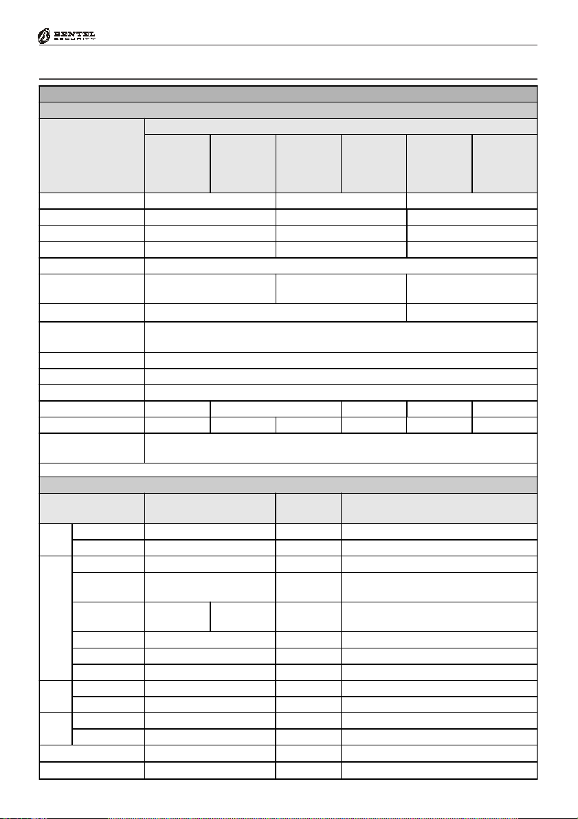
Technical Specifications
Table 1.4 - T echni cal Specificati ons
Control Panels
Values
KYO 4 M
KYO 4 M
Specifications
Volt age
KYO 4 MKYO 4 M
KYO 8 M
KYO 8 M
KYO 8 MKYO 8 M
KYO 8W M
KYO 8W M
KYO 8W MKYO 8W M
KYO 32 M
KYO 32 M
KYO 32 MKYO 32 M
230V
Maximum Current draw
Maximum Power
Power Supply Battery-charger
13.8 V
Insulation Class
Maximum Current
available for peripherals
Max. Battery Charge Current
Battery Housing
(Brand and Type)
YUASA NP7-12 FR or Equivalent with UL94-V2 (or superior) Case Flame Class
IP Protecti on Level
Recognized MF Tones
Operating Temperature
Dimensi ons mm (W x H x D) 235 x 269 x 77 309 x 227 x 89 339 x 488 x 108 309 x 227 x 89 339 x 488 x 108
Weight (without Battery)
Compli es with
CEI Normat ive Laws
2.7 Kg 1.8 Kg 1.2 Kg 5.3 Kg 1.3 Kg 5.4 Kg
EN 60950:2000 - EN50081-1:1992 - EN50130-4:1995+A1:1998 - CEI 79-2 2
KYO 4 P
KYO 4 P
KYO 4 PKYO 4 P
KYO 8 P
KYO 8 P
KYO 8 PKYO 8 P
KYO 8W P
KYO 8W P
KYO 8W PKYO 8W P
KYO 32 P
KYO 32 P
KYO 32 PKYO 32 P
~ 50Hz ±10% 100÷240 V~ 47÷63Hz 230V~ 50Hz ±10%
KYO 8 G P-SW1
KYO 8 G P-SW1
KYO 8 G P-SW1KYO 8 G P-SW1
KYO 8 GWP-SW1
KYO 8 GWP-SW1
KYO 8 GWP-SW1KYO 8 GWP-SW1
KYO 32 G P-SW1
KYO 32 G P-SW1
KYO 32 G P-SW1KYO 32 G P-SW1
KYO 8 G L-SW1
KYO 8 G L-SW1
KYO 8 G L-SW1KYO 8 G L-SW1
KYO 8 GWL-SW1
KYO 8 GWL-SW1
KYO 8 GWL-SW1KYO 8 GWL-SW1
KYO 32 G L-SW1
KYO 32 G L-SW1
KYO 32 G L-SW1KYO 32 G L-SW1
KYO 8 G P-SW2
KYO 8 G P-SW2
KYO 8 G P-SW2KYO 8 G P-SW2
KYO 8 GWP-SW2
KYO 8 GWP-SW2
KYO 8 GWP-SW2KYO 8 GWP-SW2
KYO 32 G P-SW2
KYO 32 G P-SW2
KYO 32 G P-SW2KYO 32 G P-SW2
KYO 8 G L-SW2
KYO 8 G L-SW2
KYO 8 G L-SW2KYO 8 G L-SW2
KYO 8 GWL-SW2
KYO 8 GWL-SW2
KYO 8 GWL-SW2KYO 8 GWL-SW2
KYO 32 G L-SW2
KYO 32 G L-SW2
KYO 32 G L-SW2KYO 32 G L-SW2
0,2 A 0,42 A 0,5 A
45 W 50 W 115 W
_ ±1% / 1 A 13.8 V_ ±2% / 1.5 A 13.8 V_ ±1% / 3 A
I
0.6 A 1 A 2.3 A
0.3 A 0.5 A
12V - 7Ah (17Ah in "L" model s)
IP30
Minimum Level 200 mVpp (-23 dBV)
+5 ÷ +40º C
a
ed. 1993
9
Descripti on
K4-K8-K8W-K32
Main
Main
MainMain
Board
Board
BoardBoard
K8G-K8G-K32G
MIA/S and MIA/D
ALISON/S
ALISON/DV
Keypad
Keypad
KeypadKeypad
ALISON/8L
ALISON/32LP
OMNIA/TAST-R
NC2/ TAST
ICON/KP
der
der
derder
M-OUT/6 (Output)
ECLIPSE
PROXI
M-IN/6 (Input)
Reader
Reader
ReaderReader
Expan-
Expan-
Expan-Expan-
NC2/VOX Voice Board
VectorRX Receiver
COMPONENTS and ACCESSORY ITEMS
Max. Current Draw
(mA)
Dimensions (W x H x D) mm
100 122 x 118
150 166 x 109
50 164 x 133 x 44
90 143 x 115 x 38
90 160 143 x 115 x 38
50 160 x 73 x 30
80 117 x 96 x 25
80 160 x 73 x 30
30 20 x 44 x 48
30 78 x 108 x 22
27 108 x 101 x 34
11 108 x 101 x 34
30 58 x 71
50 146 x 290 x 28
10
Multifunction Control Panel
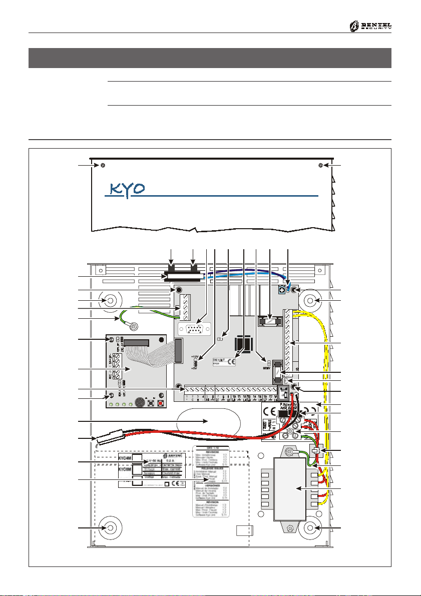
SECTION 2 - IDENTIFICATION OF COMPONENTS
The numbers in boldface in square brackets “[ ]”, in this and other Manuals
relevant to this product, refer to the components described in this section.
KYO 4 M — KYO 8 M — KYO 8W M — KYO 32 M
®®
1
11d
56
11d 9d
7
8 9a
10
11b
3a
2 2
4
13c
3a
12a
LE LI
3332 3 4 35 36
31
AC
30
REDBLKYEL
27 2928
GRN
03
25 26
KYO8
COMNC 0201+B
19 20 2221 2423
4
3a
17
15
18a
18b
1
3a
4
9c
10
3a
19c
19b
19a
18c
13a
14
2
Fig. 2.1 - KYO 32 M Control panel complete with NC2/VOX Voice Board (accessory item)
2

®®
Section 2 - Identification of Components
KYO 4 P — KYO 8 P — KYO 8W P — KYO 32 P
11
11
12b
11a
12a
13b
12b
3c
17
11e
11f
15
18a
18b
9d
51
96
9a
10 22546 783b 3b
11a
4
KYO8
9c
10
4
3c
19c
L
N
L
N
19b
19a
18c
14
2
2
Fig. 2.2 - KYO 32 Control panel complete with NC2/VOX Voice Board (accessory item)

12
Multifunction Control Panel
KYO 8G P-SW1 — KYO 8GWP-SW1 — KYO 32G P-SW1
®®
12b
11a
13b
12a
12b
10
9e
17
11e
11f
15
18b
18a
1
54683b 3b
11c
11g
29a
9d
7
29b
22
1
11a
9b
9c
BPI
+F
4
10
3c
4
LN
13b
24
28
22b
19a
26
2
Fig. 2.3 - KYO 32G P-SW1 Control panel complete with NC2/VOX Voice Board (accessory item)
20b
2
24

®®
Section 2 - Identification of Components
KYO 8G P-SW2 — KYO 8GWP-SW2 — KYO 32G P-SW2
13
11
12b
11a
12a
12b
10
3c
9e
24
11e
11f
15
17
18b
18a
26
54683b 3b
11c
11g
7
9d
29a
29b
22
11a
9b
9c
BPI
+F
4
10
3c
13b
25a
19a
27
28
23
22a
21
20a
2
2
25b
Fig. 2.4 - KYO 32G P-SW2 Control panel complete with NC2/VOX (accessory item)
3d

14
Multifunction Control Panel
KYO 8G L-SW1 — KYO 8GWL-SW1 — KYO 32G L-SW1
®®
13c
12a
11f
18b
11e
18a
3a
3a
9e
10
3e
17
15
11d
79d8
29a
11d
11b
4
1
2
4
9b
5
6
BPI
+F
9c
11c
11g
10
3a
16
29b
13c
LN
24
28
22b
19a
20b
26
Fig. 2.5 - KYO 32G L-SW1 Control panel complete with NC2/VOX Voice Board (accessory item)
24
2

®®
Section 2 - Identification of Components
KYO 8G L-SW2 — KYO 8GWL-SW2 — KYO 32G L-SW2
15
13c
12a
11f
18b
11e
18a
3a
3a
9e
10
3e
17
15
11d
79d8
29a
11d
11b
4
1
2
29b
4
9b
5
6
BPI
+F
9c
11c
11g
10
3a
16
24
19a
25a
23
27
28
22a
21
20a
26
24
25b
3d
2
Fig. 2.6 - KYO 32G L-SW2 Control panel complete with NC2/VOX Voice Board (accessory item)

16
Multifunction Control Panel
Table 2.1 - Identification the Main Unit Parts
Part Description
1 Frontplate Screws (2)
2 Locations (4) for backplate screws (Ø = 5 mm)
3a Reverse locking PCB supports (see Figure 3. 3)
3b PCB location Tabs
3c Locations (2) for PCB screws
3d Arrester for BAQ35T12 Switching Power-Supply/Battery Charger
3e 13 mm plastic support
4 Terminal Board
5 DB-9 male connector for computer link
6 BPI Level Jumper:
12Vk5V
5 V (at default);
12Vj5V
12 V
7 Firmware Release label
Stop Alarm Jumper: Open ( ) A larms Uninhibited (default);
8
Stop Alarm Jumper: Closed (K) Alarms Inhibited
9a BAT T Fuse: F8A - 250V
9b BPI Fuse (Fuse — protects BPI Bus [+] terminal): F2A - 250V
+B Fuse: F5A - 250V (K4, K8, K8W and K32 boards)
9c
+F Fuse: F5A - 250 V (Only for 'G' boards)
9d Reserved Jumper
9e Auxiliary Connector for BPI Devices (K8G, K8GW, K32 and K32G boards ONLY)
10 Connector for Tamper and Snatch Microswitches (N.O. at default)
11a Tamper Microswitch for BOX-P (A ccessory Item , code A SN C)
11b Tamper Microswitch for BOX-M and BOX-L (Accessory Item, co de MA XI-A SNC)
11c On-Board Tamper Microswitch (Only for 'G' PCBs)
11d Plastic spacers (2): inside the MAXI-A SNC Tamper Microswitch package
11e Snatch Microswitch (Accessory Item)
11f Snatch Micr oswitch bracket
Jumper for on-board Tamper-Microswitch [11c]:
11g
Open (J) Microswi tch disabled,
Closed (K) Microswitch enabled (at default)
12a Optional Voice Board (Order Code: NC2/VOX — refer to Section 5)
12b Voice Board Holder
13a Earth Wire
13b Earth Wire on PCB - terminal (L=400 mm)
13c Earth Wire on PCB - terminal (L=120 mm)
14 Power Transformer — 220-17Vac-1.5A (Order Code: TRF)
15 Battery wires
16 Cable supports
17 Cable entry
18a Marking ticket
18b Release Label
®®

®®
Section 2 - Identification of Components
Table 2.2 - Identification of the Switching Power Supply Components
Part Description
18c Cable Tie Bases
19a Mains Screw Terminal — for Mains and Earth
19b General protection Fuse: F500MA - 250
19c Adhesive Label
20a BAQ35T12 Switching Power Supply
20b BAQ15T12 Switching Power Supply
21 Mains LED (ON = Mains OK)
22a Fine Adjustment Trimmer
22b
KST Jumper — If you are connecting a KST Thermal Probe to the battery, this
jumper must be inserted.
23 Auxiliary Terminals for system peripheral (Output = 13.8 Vcc)
Screw to secure the Switching Power Supply to the backplate:
24
1 x BAQ35T12 - 2 x BAQ15T12
25a Screw for the Switching Power Supply
25b Snap Rivet
26 Thermal prob e — to be fitted to the battery (Order Code: KST)
27 Fuse — protects Switching Power Supply (F2A-250V)
28 Fuse — protects against Battery pol arity inversion (F6.3A -250V)
29a Connector for the Switching Power Supply
29b OVC-Link wire (Output Voltage Control)
17

18
Table 2.3 - Identification of the NC2/VOX Components
Part Description
LOC-MIC Jumper: K (at Default) - NC2/VOX Microphone Enabled
35
LOC-MIC Jumper: J - NC2/VOX Microphone Disabled
REM-MIC Jumper: J (at Default) - VOX-REM Remote Microphone Disabled
36
REM-MIC Jumper: K - VOX-REM Remote Microphone Enabled
37 Terminal bo ard for VOX- REM Module
REM-SP Jumper: J (at Default) - VOX-REM Remote Speaker Disabl ed
38
REM-SP Jumper: K - VOX-REM Remote Speak Enabled
LOC-SP Jumper: K (at Default) - NC2/VOX Speaker Enabled
39
LOC-SP Jumper: J - NC2/VO X Loudspeaker Disabled
40 Flat Cable
41 Microphone
42 PLAY button
43 RECORD button
44 Status LEDs
Multifunction Control Panel
®®
35 36
44
41
42
43
Fig. 2.7 - NC2/VOX Voice Board Components
37
38
39
40

®®
Section 3 - Mounting the Components
SECTION 3 - MOUNTING THE COMPONENTS
Introduction
Please read this section to get an overall view of the steps involved in installing
Control panels from the KYO Unit range.
The end of the stranded conductor must not be soft soldered in places where it is
subject to contact pressure. The Mains wiring must comply with the rules for
double or reinforced insulation. Use an adhesive cable grip to secure the wires
to the terminal boards.
Boxes and Accessories
Metal and Plastic boxes are available.
Metal box BOX-M
Plastic box BOX-P
Large Metal Box
The Metal Box (BOX-M) kit includes the following parts:
18 Balance Resistors — 10 Kohm
4 plastic PCB supports
1 x 12cm Earth wire (Yellow-Green) with eyelet [13c]
4 hexagonal nuts — M3
2 Parker screws — 2.9 x 7.5 to secure the Frontplate
The Plastic Box (BOX-P) kit includes the following parts:
18 Balance Resistors — 10 Kohm
1 x 40 cm Earth wire (Yellow-Green) without eyelet [13b]
2 Parker screws — 2.9 x 7.5 to secure the PCB
1 Parker screw — 2.9 x 9.5 to secure the BAQ35T12 Switching Power Supply
2 Parker screws — 3.9 x 9.5 to secure the Frontplate
1 Parker screw — 3 x 14.2 to secure the Mains Screw Terminal
2 Parker screws — 3 x 8 to secure the Transformer or BAQ15T12.
The Large Metal Box (BOX-L) kit includes the following parts:
BOX-L
18 Balance Resistors — 10 Kohm
1 x 13 mm plastic support for the PCB
4 plastic supports for the PCB
2 x 12 cm Earth wire (Yellow-Green) with eyelet [13c]
1 hexagonal nut — M3
1 plastic Snatch microswitch bracket [11e]
2 x 3mm cogged metal washers
2 screws 3x6
2 screws 3x8
2 Parker screws — 2.9 x 7.5 to secure the frontplate
1 “Protected Enviroment” label
19

20
Multifunction Control Panel
Installing the Transformer and Mains Screw Terminal - Fused
The Transformer (see Fig. 3.1) package includes the following parts:
1 Mains Screw Terminal - Fused [19a] — 500 mA
1 Adhesive Label [19c] for the Mains Screw Terminal
1 x 12 cm Earth wire (Yellow-Green) with eyelet [13a] for earthing the
Metal box or Transformer
To install the Transformer (Order Code TRF), work carefully through the following steps (refer to Fig. 3.1).
Metal box (BOX-M)
1. Stick the label [19c] onto the backplate (one aperture must be positioned
over the fixed screw, and the other over the Mains Terminal [19a] screw
location.
2
. Fit the Mains Screw Terminal [19a] onto the fixed screw (as indicated on
the label) then, using the hexagonal nut, secure it to the backplate.
3
. Mount the Transformer onto the 2 fixed screws (M3x10) on the backplate
of the Metal box.
. Fit the eyelet terminal [13a] to the fixed screw (as shown in Fig. 3.2a) then,
4
using two hexagonal nuts, secure the transformer to the backplate.
5
. Connect the Transformer primary (RED wires) to terminals [N] and [L].
6
. Connect the free end of the Earth wire [13a] to the [
Mains Screw Terminal [19a] (as shown in Fig. 3.2a).
Use the cable tie bases (refer to [18c] in Fig. 2.1) to bunch the Red wires of the
Transformer and the Earth wire [13a].
QQ
Q ] terminal on the
QQ
®®
[19c]
[19a]
M3 Nut to secure
Mains Terminal
71.75 mm
Metal Box — BOX-M Plastic Box — BOX-P
Fixed screws
M3x10
Screw Location Ø 2.5mm
Fig. 3.1 - Installing the Transformer and Mains Terminal board
71.75 mm
[19c]
[19a]
Screw to secure
Terminal board

®®
Section 3 - Mounting the Components
21
Plastic box (BOX-P)
1. Stick the label [19c] onto the backplate (as shown in Fig. 3.1). Ensure that
the 2 label holes correspond to the 2 holes on the backplate.
2
. Place the Mains Screw Terminal onto the screw location (Ø 2.5) then, using
the Parker screw (3 x 14.2) secure it to the backplate.
. Using the 2 holes on the backplate as reference, mount the Transformer
3
[14] (as shown in Fig. 3.2b).
4
. Using the two 3 x 8 parker screws, secure the Transformer to the backplate.
5
. Connect the Transformer primary (RED wires) to terminals [N] and [L].
[13a]
Hexagonal
nuts M3
Metal Box — BOX -M
Fig. 3.2 - Connecting the Earth wire [13a]
51
96
Fig. 3.3 - Fitting the Reverse Locking PCB Supports

22
Multifunction Control Panel
Mounting K4-K8-K8W-K32 PCBs
Please read this section to get an overall view of the steps involved in installing
K4, K8, K8W and K32 PCBs in Metal and Plastic boxes.
Metal box (BOX-M)
For the following procedure, see Fig. 2.1.
1
. Insert the 4 reverse locking PCB supports [3a] into their locations on the
backplate, then attach the PCB. If you are installing an NC2/VOX Voice
Board, insert the supports (LEDs to the bottom), then attach the NC2/
VOX Voice board (see Fig. 3.3).
. Using a hexagonal nut (M3), secure the Earth wire (Yellow-Green) eyelet
2
[13c] to the screw (M3x10) on the backplate.
3
. Connect the other end of the Earth wire (Yellow-Green) to terminal 36
--
(
- ) on the PCB.
--
4
. Connect the Transformer secondary (YELLOW wires) to terminals 30-31
(AC) on the PCB.
. If you are fitting a Tamper microswitch [11b], insert the two spacers [11d]
5
then, using the two hexagonal nuts( M3), secure it to its location (see Fig.
3.3). Connect the wire to the connector [10].
Plastic box (BOX-P)
For the following procedure, see Fig. 2.2.
1
. Slide the PCB under the 2 tabs [3b].
. Using the 2 (2.9 x 7.5) Parker screws (in screw locations [3c]), secure the
2
PCB to the backplate.
3
. Connect one end of the Earth wire (Yellow-Green) [13b] to the [
terminal (36) on the PCB, and the other to the [
Screw Terminal [19a].
Use the cable tie bases (refer to [18c] in Fig. 2.2) to bunch the Red wires of the
Transformer and the Earth wire [13b].
. Connect the Transformer secondary (YELLOW wires) to terminals 30-31
4
(AC) on the PCB.
5
. If you are fitting a Tamper microswitch [11a], insert it into its location, then
connect the wire to one of the two connectors [10] on the PCB. The second
connector [10] can be used for an external Tamper microswitch (on the
outside of the cabinet).
6
. If you are fitting a Snatch microswitch [11e], insert it into its location, then
connect the wire to terminals no. 5 and no. 6 (AS) and connect, in series, a
10 Kohm EOL resistor.
--
- ]
--
QQ
Q ] terminal on the Mains
QQ
®®
NOTE: Cut off the Snatch microswitch connector before connecting the wire.

®®
Section 3 - Mounting the Components
Installing ‘G’ series PCBs (K8G-K8GW-K32G)
Please read the following instructions, to get an overall view of the steps
involved in installing K8G, K8GW and K32G PCBs. “G” series PCBs can be
installed in plastic boxes (BOX-P) and large metal boxes (BOX-L).
Plastic box (BOX-P)
For the following procedure, refer to Fig. 2.3 and Fig. 2.4.
1
. Slide the PCB under the 2 tabs [3b].
. Using the 2 (2.9 x 7.5) Parker screws (in screw locations [3c]), secure the
2
PCB to the backplate.
3
. If you are fitting a Tamper microswitch [11a ], insert it into its location, then
connect the wire to one of the two connectors [10] on the PCB (see Fig. 2.3
or 2.4). The second connector [10] can be used for an exterrnal Tamper
microswitch (on the outside of the cabinet).
4
. If you are fitting a Snatch microswitch [11e], insert it into its location, then
connect the wire to connector [10].
Metal box BOX-L
For the following procedure, refer to Fig. 2.5 and Fig. 2.6.
1
. Insert the plastic support [3e] into its location.
2
. Insert the 4 reverse locking PCB supports [3a] into their locations on the
backplate, then attach the PCB (see Fig. 3.3). If you are installing an NC2/
VOX Voice Board, insert the supports [3a], then attach the NC2/VOX
Voice board (LEDs to the left).
. Using a hexagonal nut (M3), secure the Earth wire (Yellow-Green) eyelet
3
[13c] to the soldered screw on the backplate.
4
. Connect the other end of the Earth wire (Yellow-Green) [13c] to terminal 51
--
(
- ) on the PCB.
--
5
. If necessary, remove the Jumper [11g] in order to disable the Tamper micro-
switch [11c ].
. If you are fitting a Tamper microswitch [11b], insert the two spacers [11d]
6
then, using the two hexagonal nuts (M3), secure it to its location (see Fig.
3.3). Connect the wire to the connector [10].
7
. If you are fitting a Snatch microswitch [11e ], position the bracket [11 f]
then, using the two hexagonal nuts (M3), secure the Snatch microswitch to
its location. Connect the wire to the connector [10].
23

24
Multifunction Control Panel
Installing the Switching Power Supply
Please read the following instructions to get an overall view of the steps involved in installing Switching Power Supplies in ‘G’ series Control panels (i.e.
Control panels with K8G, K8GW and K32G PCBs). Two Switching Power
Supplies are available:
SW1) BAQ 15T12 (1,5 A)
SW2) BAQ 35T12 (3 A)
Installing BAQ15T12 Switching Power Supplies
BOX-P Plastic Box
To install a BAQ15T12 in a plastic box, work carefully through the following
steps (see Fig. 2.3 and 3.5).
1
. Using the 2 holes on the backplate as reference, mount the BAQ15T12 to
the backplate.
. Using the 2 Parker screws [24] (3 x 8), secure the BAQ15T12.
2
3
. Connect one end of the Earth wire (Yellow-Green) [13b] to the Earth
terminal 51 (
--
- ) on the PCB, and the other to terminal [
--
BAQ15T12 Switching Power Supply.
4. Plug the Switching Power Supply into the connector [29a] on the PCB.
. Connect one end of the OVC-Link wire [29b] to the OVC connector on
5
the PCB, and the other to the NTC connector on the BAQ15T12. This
connection will allow the system to monitor the battery status constantly.
QQ
Q ] on the
QQ
®®
BOX-L
Large Metal Box
To install a BAQ15T12 in a metal box, work carefully through the following
steps (see Fig. 2.5 and 3.5).
1
. Using the 2 holes on the backplate as reference, mount the BAQ15T12 to
the backplate.
2
. Using the 2 screws [24] (3 x 8), secure the BAQ15T12.
3. Connect one end of the Earth wire (Yellow-Green) [13c] to the Earth
terminal [
QQ
Q ] on the BAQ15T12 then, using the screw (3x6) and washer,
QQ
secure the other end to its location on the backplate (see Fig. 2.5).
4
. Plug the Switching Power Supply into the connector [29a] on the PCB.
5. Connect one end of the OVC-Link wire [29b] to the OVC connector on
the PCB, and the other to the NTC connector on the BAQ15T12. This
connection will allow the system to monitor the battery status constantly.

®®
Plastic Box BOX-P
BOX-L
Large Metal Box
Section 3 - Mounting the Components
25
Installing BAQ35T12 Switching Power Supplies
To install a BAQ35T12 in a plastic box, work carefully through the following
steps (see Fig. 2.4 and 3.5).
1. Locate the BAQ35T12 onto its supports on the backplate. Ensure that the
Switching Power Supply is secured firmly in place by the arrester [3d].
. Using the Parker screw [24] (2.9 x 9.5), secure the BAQ35T12 in place.
2
3
. Connect one end of the Earth wire (Yellow-Green) [13b] to terminal 51
--
(
- ) on the PCB, and the other to terminal [
--
Switching Power Supply.
4
. Insert the Switching Power Supply plug into the connector [29a] on the
PCB.
. Connect one end of the OVC-Link wire [29b] to the OVC connector on
5
the PCB, and the other to the NTC connector on the BAQ15T12. This
connection will allow the system to monitor the battery status constantly.
To install a BAQ35T12 in a metal box, work carefully through the following
steps (see Fig. 2.6 and 3.5).
1
. Locate the BAQ35T12 onto its supports on the backplate. Ensure that the
Switching Power Supply is secured firmly in place by its arrester [3d].
. Using the washer and screw [24] (3 x 6), secure the BAQ35T12 in position.
2
3. Insert the Switching Power Supply plug into the connector [29a] on the
PCB.
4. Connect one end of the OVC-Link wire [29b] to the OVC connector on
the PCB, and the other to the NTC connector on the BAQ35T12. This
connection will allow the system to monitor the battery status constantly.
QQ
Q ] on the BAQ35T12
QQ
Replacing BAQ35T12 Fuse
Please read the following instructions, to get an overall view of the steps
involved in replacing the Fuse [28] of the BAQ35T12 Switching Power Sup-
ply (see Fig. 2.4).
1
. Disconnect the Mains Power.
. Remove the snap rivet [25b].
2
3
. Remove the screws [25a].
4
. Remove the cover, then replace the Fuse.
. Replace the cover, snap rivet [25b] and screw [25a].
5
6
. Restore the Mains Power.
IMPORTANT - If the Mains Fuse [27] blows, DO NOT replace it. This
condition indicates general malfunction and requires specialist intervention,
Therefore, return the Switching Power Supply to your nearest Service Centre
for repair.

26
Multifunction Control Panel
Earthing the PCB
The PCB must be earthed by means of the Earth wire ([13a], [13b] or [13c]), in
order to protect it from electrical surges from the Telephone Line, and comply
with Safety Regulations.
Marking Ticket
Once you have assembled the components, specify the type of Control panel
that you have constructed.
Using an indelible pen, tick the relevant box on the Marking Ticket [18] (as
shown in Fig. 3.4).
NOTE: SW1 indicates the presence of a BAQ15T12 Switching Power Supply (1.5
A), and SW2 indicates the presence of a BAQ35T12 Switching Power Supply (3 A).
Connecting the KST Thermal Probe
‘G’ series PCBs have on-board connectors (PTC in Fig. 3.5.) for KST Thermal
Probes [26]. Addition of a KST Thermal Probe will optimize the Battery Charge
process, by regulating the Battery Charge Voltage in accordance with the Battery
temperature. The probe must be attached to the Battery by means of adhesive tape.
The KST connection cannot be considered complete until the OVC-Link Wire
[29b] (supplied with the Switching Power Supply) has been connected.
®®
Using an in delib le pen ,
corresponds to the assembled
Fig. 3.4 - Marking Ticket
Marking Ticket for BOX-M and BOX-L Metal Box
tick the box that
Control panel
Marking Ticket for BOX-P Plastic Box
If the Con trol panel is equipped
with a Transformer
(Order Code TRF), tick the box that
corresponds to the assembled
Control panel
If the Control panel
is equipped with a
Switching Power Supply,
tick the box that corresponds
to the assembled Control panel
(SW1= BAQ15T12, S W2=BAQ35T 12)

®®
Section 3 - Mounting the Components
If you are connecting a KST thermal probe to a Control panel with a BAQ15T12
Power Supply, ensure that the BAQ15T12 on-board Jumper [22b] is inserted.
For further information, refer to the Insert in the KST package.
Connecting the NC2/VOX Voice Board
To install the NC2/VOX Voice Board, work carefully through the relevant steps
(Metal box or Plastic box), and refer to Fig. 3.6.
NOTE: If you are connecting an NC2/VOX Voice Board to a Control panel
that is already in service, ensure that the Mains and Battery have been DISCONNECTED before starting the connection procedure.
Metal box
1. Remove the paper from the self-adhesive rubber gasket, and position it in
the centre of the 4 board support locations on the backplate.
2. Insert the reverse-locking board supports [3a], then attach the NC2/VOX
(refer to Fig. 3.3). If you are using a BOX-L, locate the boar as shown in Fig.
2.5 or 2.6.
3. Connect the Flat cable to connector A on the NC2/VOX Voice board, and to
Connector B on the PCB.
Plastic box
1. Slot the NC2/VOX board in the holder [12b] — LEDs to the top.
2. Connect the Flat cable to connector A on the NC2/VOX Voice board, and to
Connector B on the PCB.
27
PTC Connector OVC Connector
Control Circuit (PCB)
Fig. 3.5 - Connecting the KST Thermal Probe to ‘G’ series PCBs
KYO UNIT
Battery
KST Thermal
Probe
OVC-Link
NTC Connector
Switching
Power Supply
(BAQ35T12 or BAQ15T12)

28
Multifunction Control Panel
®®
BACKPLATE
CONTROL
A B
[12]
CIRCUIT
(PCB)
GASKET
[12]
CONTROL
CIRCUIT
(PCB)
A B
Fig. 3.6 - Installing the NC2/VOX Voice board in Metal box (Left) or Plastic box (Right)
PCB Identification Label
The self-adhesive PCB Identification Label (supplied with the PCB) should be
located on the frontplate, as shown in Fig. 3.7.
BACKPLATE
Locate the PCB
Identification Label here
KYO 32
Fig. 3.7 - Locating the PCB Label
Locate the PCB
Identification Label here
KYO 32G

®®
Section 4 - Installing the Control Panel
SECTION 4 - INSTALLING THE CONTROL PANEL
Mounting the Control Panel
The Control panel must be mounted in a safe, dry place, close to the placement
of command devices (Keypads, Readers, etc.). Once you have selected a
mounting location and created a layout, ensure that you will be able to connect
the Mains and Telephone line.
The Main Unit must be at least 2 metres from GSM and radio relay systems.
To mount the backplate:
. Remove the screws [1] and frontplate.
1
2
. Pull the cables through the wire entry [17], then using 4 anchor screws for
all the screw locations [2], secure the backplate to the wall.
3
. Complete the connections on the Terminal board [4] (refer to Table 4.1).
GG
G - In order to comply with safety regulations, the Mains power
GG
supply must be fitted with a bipolar insulating device (e.g. Automatic
isolating switch) for protection against overvoltage and short-circuit
(see Fig. 4.1a).
29
4. Connect the Mains power supply to the Mains terminal [19a]: Neu-
tral to terminal [N], Phase to terminal [L] and Earth to terminal [
Phase
230 V
Neutral
50 Hz
Earth
Control Panel
a b
Fig. 4.1 - Connecting the Insulating device
18c
QQ
Q ].
QQ

30
Multifunction Control Panel
NOTE: In order to comply with the Safety Regulations in force,
this device must be protected against electrical surges (e.g. from the
Telephone Line), therefore, it must be properly connected to the
Mains Earth line. The warranty does not cover damage to the PCB
caused by non-connection, or improper connection to a faulty Mains
Earth line.
Use the cable tie bases (refer to [18c] in Fig. 4.1b) to bunch the 220 V Mains
wires and the Earth wire.
. Disable the Alarm Output, as described in the following paragraph ‘Open-
5
ing and Closing the Control panel’.
. Connect the battery wires [15].
6
7
. Program the Control panel, as described in the INSTALLATION
MANUAL.
8
. Close the Control panel then, using the 2 screws [1], secure the Frontplate.
Opening and Closing the Control Panel
If the Tamper microswitches ([11a ], [11b] or [11c]) are enabled, do not open the
Control panel until you have disabled the Alarm output.
To open the Control panel:
Opening the Control
Closing the Control
1. Enter the Installer Code at any Keypad, then press ENTER (press
panel
MIA Keypads or
EE
E on ALISON Keypad).
EE
2. Remove the screws [1] and Frontplate.
3. Insert the Stop Alarm Jumper [8].
To close the Control panel:
1. Remove the Stop Alarm Jumper [8].
panel
2. Replace the Frontplate and screws [1]
3. Exit the Menu (as described in the PROGRAMMING FROM KEYPAD
Manual). The system will become operative when you exit the Menu.
EE
E on
EE
®®
NOTE: If you are using a LED Keypad, press the e key to exit Menu.

®®
Section 4 - Installing the Control Panel
Table 4.1 - Description of the Terminals
PCB Terminals
K8G - K8GW - K32G K4 - K8 - K8W - K32
1-2-3-4
[+][C][R][-]
5 [AS] 17 [A S]
6-9-12-15-18-21-24-
27-30-37
[MMMM]
7-10-13-16-19-22-25-28
[+F]
8-11-14-17-20-23-26-29
[L1] ... [L8]
4-6-8-11-14-17
[MMMM]
22 [+B]
7-9-10-12-13-15-16-18
[L1] ... [L8]
Terminals for the BPI Device connections
(Keypads, Readers, Expander, etc.)
Balanced 10K Tamper Line ––
Negative Terminal 0 –
Positive Terminal — power supply to the
Detectors
Programmable Alarm Lines
(KYO4 manages Lines L1 ... L4)
Description
Free Voltage Changeover A larm Relay:
31-32-33
[NC][COM][NO]
19-20-21
[NC][NO][COM]
during Standby COM Terminal
connected to NC (NO floating)
during Alarm COM Terminal
connected to NO (NC floating)
Positive is present on this termi nal
34 [+N] –
during Standby
this Terminal is Open during Alarm
Positive is present on this termi nal
35 [+A] –
during Alarm
this Terminal is Open during Standby
36
[+B]
–
38-39-40-41-42
[O1][O2][O3]
[O4][O5]
43-44-45-46
[GRN][YEL]
[BLK][RED]
47-48
[LE]
49-50
[LI]
51
[----]
– 30-31 [AC]
22
[+B]
23-24-25
[O1][O2][O3]
–
26-27-28-29
[GRN][YEL]
[BLK][RED]
32-33
[LE]
34-35
[LI]
36
[----]
Auxiliary Power Supply for peripherals 13.8 (*)
150 mA Auxiliary Open-Collector
Outputs — Programmable
500 mA Auxiliary Open-Collector
Outputs — Programmable
Key Bus Terminals (if present):
RED Positive BLK Negative
External Telephone Line Terminals ––
Terminal for line-sharing devices (Fax,
Modem, Telepho ne, etc.) — connected to
the same Telephone line as the P anel
Terminal for the Earth connection ––
Terminals for the Transformer
secondary connection
(*) - the total c urre nt d raw o f the se te rminal s m ust not ex cee d :
(*) -
- for K4, K8, K8W and K32 with Transforme rs
0.6 A
(*) - 1 A - for K8G-SW1, K8GW-SW1 and K32G-SW1 with the BAQ15T12 Switching Power Supply
(*) - 2.3 A - for K8G-SW2, K8GW-SW2 and K32G-SW2 with the BAQ35T12 witching Powe r Sup ply
(*) - (the Battery Charge value must be subtracted from these values)
Volta ge
(V)
Current
Max. (A)
13.8 (*)
13.8 (*)
––
––
13.8 (*)
13.8 (*)
–
0.15
(*)
0.5
(*)
13.8 (*)
––
––
31

32
Multifunction Control Panel
SECTION 5 - INSTALLING THE NC2/VOX
The NC2/VOX Voice Board (Accessory Item) will allow you to record and
send Voice messages to the programmed Telephone numbers. For the installation instructions refer to Section 3 under ‘NC2/VOX’.
General Features
Voice synthesizer — Records/Plays Messages
Records 8 Messages: 4 x 15 seconds and 4 x 7 seconds
Repeats the Alarm Message up to 4 times
Loudspeaker
Talk Listen-in function (Telemergency)
Additional VOX-REM Modules
If the NC2/VOX Voice Board is unable to cover the entire premises (e.g. due to
the size of the building), you can extend cover by using additional VOX-REM
Modules (Microphone and Loudspeaker). The additional VOX-REM Modules can be located as required (see Fig. 5.1).
®®
VOX-REM Jumpers
GG
G - For proper operation, the wire length between the additional VOX-REM
GG
Module and the NC2/VOX Voice Board should not exceed 50 metres.
The ALISON/DV Keypad has a built-in Microphone [60a] and Loudspeaker
[60b] which perform the same operations as the VOX-REM Module. Fig. 5.1
illustrates connections of a VOX-REM Module and an ALISON/DV Keypad.
Additional VOX-REM Modules must be connected in parallel to the NC2/VOX
Voice Board (see Fig. 5.1).
Installing Additional VOX-REM Modules
The VOX-REM must be mounted in 2 separate boxes (Minibox), as shown in
Fig. 5.1: one for the board and the other for the loudspeaker.
If you intend using the VOX-REM Microphone, you must insert the Jumper
marked EN LOC MIC.
If you intend using a remote Microphone, you must insert the Jumper marked
EN REM MIC. The Microphone must be connected to the connector marked
MIC on the VOX-REM Module.
NOTE: Use shielded cable for all connections. For proper operation, the wire
length must not exceed 2 metres.
The Loudspeaker must be connected to the bipolar connector (see Fig. 5.1).

®®
Section 5 - Installing the NC2/VOX
33
NC2/VOX Jumper
Settings
NOTE: If you connect a VOX-REM Module, you must set the jumpers on the
NC2/VOX as follows:
LOC-MIC Open (oo)
REM-MIC Closed (//)
LOC-SP Open (oo )
REM-SP Closed (//)
GG
G - The NC2/VOX supports up to 4 additional VOX-REM Modules.
GG
Record / Play Messages
Put the system in SERVICE Mode (as per maintenance) by inserting the
Jumper [8] (as described in Section 4 under ‘Opening and Closing the Control
panel’), or by using a valid SAT key (with the Service attribute) at an
ECLIPSE Reader.
VV
The
V LED on the Keypad will blink, and the 4 Green LEDs on the NC2/VOX
VV
will go through the 8 message configurations (refer to the ‘Select Message’).
LED
MIC
EN LOC MIC
EN REM MIC
BL229
+
SP+
SP-
MIC
Loudspeaker Connector
Fig. 5.1 - Installing Additional VOX-REM Modules
VOX-REM
Additional Module
MIC MIC
SP– SP–
SP+ SP+
NC2/VOX
Voice Board
ALISON-DV
MIC
SP–
SP+

34
Message No. 1 2 3 4 5 6 7 8
Length 15 sec 15 sec 15 se c 15 sec 7 sec 7 sec 7 sec 7 sec
LED 1
LED 2
LED 3
LED 4
ON
OFF
OFF OFF
OFF OFF OFF
Multifunction Control Panel
Table 5.1 - Selecting the Message
OFF OFF OFF OFF
ON
OFF OFF
ON
OFF
ON ON ON ON
ON
ON ON
ON ON ON
OFF
ON ON
OFF
Selecting Messages
The Voice Board can record up to 8 Alarm messages. Four messages of 15
seconds (messages 1, 2, 3 and 4), and four of 7 seconds (messages 5, 6, 7 and
8). The 8 message configurations (refer to Table 5.1) can be viewed on the Green
LEDs at 1 second intervals.
To select a message: press and hold keys [42] and [43] until the required configuration is shown on the LEDs.
Recording Alarm Messages
Press and hold key [43] until the 4 LEDs start to blink to signal the elapsing
message time (7 or 15 seconds).
You can start recording the Alarm message, as soon as you release the key.
Speak at a distance of approximately 20 cm from the Microphone.
Recording will stop automatically when the message time elapses. You can stop
recording at any moment by pressing key [43].
®®
ON
OFF
Playing Messages
Press and hold key [42] until the 4 LEDs start to blink to signal the elapsing
message time (7 or 15 seconds).
The Alarm Message will play.
You can stop playback at any moment by pressing key [42].

®®
Programming
Activation
Section 5 - Installing the NC2/VOX
35
Proper operation of the NC2/VOX Voice Board depends on Telephone and
the Events pages (refer to ‘Programming from PC’ in the ‘INSTALLATION
MANUAL’).
Fig. 5.2 shows the various phases of the Alarm call procedure. If a messagerelated event occurs, the Control panel will perform the following actions:
1. Engage the Telephone line.
2. Wait 10 seconds for the Dial Tone.
- If the Dial Tone is recognized, it will go to step 3.
- If the Dial Tone is not recognized, it will hang up and go back to step 1.
NOTE: In some cases, the Dial Tone check must be disabled (for example,
if the system is connected to a Switchboard which operates with non-standard tones). If the Dial Tone check is disabled, step 2 will be ignored.
3. Dial the programmed Telephone number.
4. Wait 30 seconds for the Line Free Tone.
- If the Line Free Tone is recognized, it will go to step 5.
- If the Line Free Tone is not recognized, it will hang up and go back to
step 1.
5. Wait 20 seconds for a Valid Handshake.
- If a Valid Handshake is recognized, it will go to step 5.
- If a Valid Handshake is not recognized, it will hang up and go back to
step 1.
6. Play the respective Alarm message 4 times.
- If a call is unsuccessful (for example, unanswered or invalid handshake), it
will make 8 tries before quitting.
NOTE: If several events occur simultaneously, the relative Alarm messages will
be played in chronological order during the same Telephone call.
Maximum 8 times
Phase 1
Enage
Line
Fig. 5.2 - Voice Message Flow Chart
Phase2
Dial
Ton e?
Phase3
Dial
Number
Hang up!Hang up!Hang up!
Phase 5Phase 4
Answer?Free?
Phase 6
Play Message
4 times

®®
BENTEL SECURITY S.r.l. - C.da Ravigliano, Z.I. S. Scolastica - 64013 CORROPOLI - TE - ITALY
Tel.: +39 0861 839060 - Fax: +39 0861 839065
E-mail: info@bentelsecurity.com - http://www.bentelsecurity.com
ISTUCBLEUNKYO 2.0 231104 P70
 Loading...