

Page 1
®
INSTALLATION MANUAL
Page 2

Via Gabbiano, 22 - Z.I. S.Scolastica - 64013 CORROPOLI (TE) - ITALY
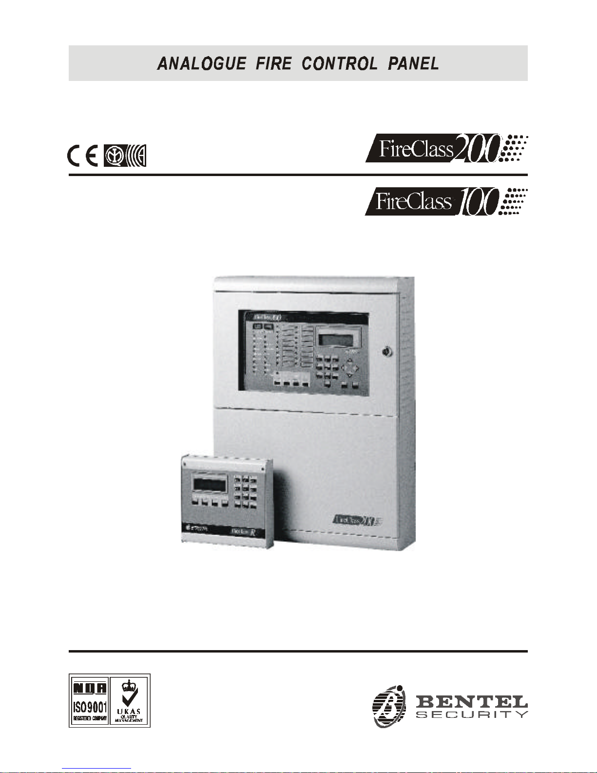
Installation manual: Analogue Fire Control Panel FireClass200
Istruzioni Inst. Inglese Antin. FC200/UK ISTINSFC200/UK
The following versions of the Fireclass200 series are available:
FC200 - Master panel with 4 A Linear power supply;
FC200/S - Master panel with 2.5 A Switching power supply;
FC200/SL - Slave panel without power supply unit;
f a technical feature is common to all versions, the name Fireclass200 is used in the description.
If a technical feature applies to a specific version, the name of the version concerned is specified.
Proper functioning of the FireClass200 components can be guaranteed ONLY when ambient
conditions, external to the cabinet, comply with the 3k5 category of IEC 721-3-3:1978.
The Loops of the FireClass200 control panel support 396 Analogue Devices.
The Conventional Zone of the FireClass200 control panel supports30 Conventional Devices.
The Fireclass200 supports a maximum of 512 devices in all.
In order to meet standards and qualify for IMQ Certification, the FC200/SL Slave panel must
be equipped with a BENTEL BA424 (27.6 V - 4 A) Linear power supply or
BENTEL BAQ60/24 (27.6 V - 2.5 A) Switching power supply.
Only the Manufacturer (Access Level no. 4 — refer to “Accss Levels” section) can install the
FC200/SL Slave panel power supply.
The FC200/SL Slave panel can operate ONLY when connected to a FireClass200 Master panel.
BENTEL SECURITY srl reserves the right to change the technical features of this product
without prior notice.
Fc100 - Master panel with 2.5 A Switching power supply;
I
FC200 - FC200/S - FC200/SL - FC100:
.
Hereby, Bentel Security,
declares the above mentioned Control Panels to be in compliance with the essential
requirements and other relevant provisions of Directive 1999/5/EC
These Control Panels comply with
Installation of these systems must be carried out strictly in accordance with the instructions
described in this manual, and in compliance with the local laws and bylaws in force
The above mentioned Control panels have been designed and made to the highest
standards of quality and performance.
The manufacturer recommends that the installed system should be completely tested
at least once a month.
The complete R&TTE Declaration of Conformity for each Panel can be found
at www.bentelsecurity.com/dc.html.
.
.
BENTEL SECURITY Srl shall not assume the responsibility for damage arising from
improper application or use. The above mentioned Control panels have no user-friendly
components, therefore, should be serviced by authorized personnel only.
EN54-2EN54-4 1999;
Page 3

TABLE OF CONTENTS
FC200 and FC100 . . . . . . . . . . . . . . . . . . . . 6
OVERVIEW 7
Access Levels . . . . . . . . . . . . . . . . . . . . . . 7
Main Features . . . . . . . . . . . . . . . . . . . . . . 7
Options with requirements . . . . . . . . . . . . . . . . 8
Telecom Module FC200/COM (Accessory item) . . . . . 8
Alarm cycle . . . . . . . . . . . . . . . . . . . . . . . . 8
Upgraded/New technical features (Firmware
version 4.00) . . . . . . . . . . . . . . . . . . . . . . 10
PARTS IDENTIFICATION 11
Main unit (FireClass200) . . . . . . . . . . . . . . . . . 11
Output Expander (FC200/6OUT) . . . . . . . . . . . . 18
Loop Interface . . . . . . . . . . . . . . . . . . . . . . 18
Telecom Module FC200/COM . . . . . . . . . . . . . . 19
Repeater . . . . . . . . . . . . . . . . . . . . . . . . . 20
INSTALLATION 21
Mounting the Control panel . . . . . . . . . . . . . . . 21
Installing Output expanders (FC200/6OUT) . . . . . . 22
Installing the Telecom Module (FC200/COM) . . . . . 22
Installing Repeater Panels (FC200/REP) . . . . . . . 22
Completing the Connections . . . . . . . . . . . . . . 23
Main board terminals . . . . . . . . . . . . . . . . . . 23
Connectiing Addressable Analogue Devices . . . . . 26
Connecting Conventional Devices . . . . . . . . . . . 28
Connecting Repeaters and Slave Panels . . . . . . . 29
Connecting Output Devices . . . . . . . . . . . . . . . 30
Bell Outputs . . . . . . . . . . . . . . . . . . . . . . . 30
Connecting the Telecom Module (FC200/COM) . . . . 31
Connecting the Power Supply . . . . . . . . . . . . . 32
Maintenance . . . . . . . . . . . . . . . . . . . . . . . 33
3
Page 4

USING THE SYSTEM 35
Operating the system . . . . . . . . . . . . . . . . . . 35
Accessing the system . . . . . . . . . . . . . . . . . . 37
PROGRAMMING 39
Auto (Autolearning - Automatic enrolling) . . . . . . . 40
Connections: Loop 1 and Loop 2 . . . . . . . . . . . . 41
Connections: Network . . . . . . . . . . . . . . . . . 43
Programming: Fire detectors . . . . . . . . . . . . . . 44
Programming: Input modules . . . . . . . . . . . . . . 46
Programming: Output modules . . . . . . . . . . . . . 47
Programming: Conventional Zone module . . . . . . . 49
Programming: Repeaters and Slave panels . . . . . . 49
Devices . . . . . . . . . . . . . . . . . . . . . . . . . . 50
Loop 1 and Loop 2 . . . . . . . . . . . . . . . . . . . 50
Conventional Line . . . . . . . . . . . . . . . . . . . . 51
Bell Outputs . . . . . . . . . . . . . . . . . . . . . . . 52
Network . . . . . . . . . . . . . . . . . . . . . . . . . 53
Password (PassWD) . . . . . . . . . . . . . . . . . . . 54
Welcome Message (MesINI) . . . . . . . . . . . . . . . 55
Zones . . . . . . . . . . . . . . . . . . . . . . . . . . . 56
OPTION . . . . . . . . . . . . . . . . . . . . . . . . . . 57
Prealarm time (P) . . . . . . . . . . . . . . . . . . . . 58
Warning Threshold (W) . . . . . . . . . . . . . . . . . 58
Alarm Verify (V) . . . . . . . . . . . . . . . . . . . . . 59
Drift Compensation . . . . . . . . . . . . . . . . . . . 60
Timer and Special Timer (T and S) . . . . . . . . . . . 61
Delay . . . . . . . . . . . . . . . . . . . . . . . . . . 63
Pulse . . . . . . . . . . . . . . . . . . . . . . . . . . 64
Extinction Mode . . . . . . . . . . . . . . . . . . . . . 64
System . . . . . . . . . . . . . . . . . . . . . . . . . . 66
Date and Time . . . . . . . . . . . . . . . . . . . . . 66
Blink . . . . . . . . . . . . . . . . . . . . . . . . . . . 67
Wires . . . . . . . . . . . . . . . . . . . . . . . . . . 67
Silence mode . . . . . . . . . . . . . . . . . . . . . . 68
Walk Test . . . . . . . . . . . . . . . . . . . . . . . . 69
Network . . . . . . . . . . . . . . . . . . . . . . . . . 70
4 Analogue Fire Control Panel FireClass200
Page 5

Printer . . . . . . . . . . . . . . . . . . . . . . . . . . 71
Verify . . . . . . . . . . . . . . . . . . . . . . . . . . . 71
Factory . . . . . . . . . . . . . . . . . . . . . . . . . . 72
Restore default . . . . . . . . . . . . . . . . . . . . . 72
Maintenance . . . . . . . . . . . . . . . . . . . . . . 72
Telephone . . . . . . . . . . . . . . . . . . . . . . . . 73
Dial. (Telephone Dialler) . . . . . . . . . . . . . . . . 74
Digital Telephone Communicator (Digital Commun.) . . 76
Telephone Numbers (T.Num) . . . . . . . . . . . . . 78
Options . . . . . . . . . . . . . . . . . . . . . . . . . 78
Remote management . . . . . . . . . . . . . . . . . . 80
MODIFYING 81
Disable . . . . . . . . . . . . . . . . . . . . . . . . . . 82
Delete Verify . . . . . . . . . . . . . . . . . . . . . . . 84
Delete Log (Del. Log) . . . . . . . . . . . . . . . . . . 85
Telecom Module . . . . . . . . . . . . . . . . . . . . . 85
READING PARAMETER 87
Devices/Zones/Outputs . . . . . . . . . . . . . . . . . 87
Options . . . . . . . . . . . . . . . . . . . . . . . . . . 88
Version . . . . . . . . . . . . . . . . . . . . . . . . . . 88
Log . . . . . . . . . . . . . . . . . . . . . . . . . . . . 89
Log data . . . . . . . . . . . . . . . . . . . . . . . . 90
Print . . . . . . . . . . . . . . . . . . . . . . . . . . . . 91
Telecom Module . . . . . . . . . . . . . . . . . . . . . 92
QUICK GUIDE 95
General features . . . . . . . . . . . . . . . . . . . . . 95
Terminals . . . . . . . . . . . . . . . . . . . . . . . . . 96
Notes . . . . . . . . . . . . . . . . . . . . . . . . . . . 98
Notes . . . . . . . . . . . . . . . . . . . . . . . . . . . 99
5
Page 6

FC200 and FC100 Features
FC200 FC100
EN54 Approved EN54 Approved
2 analogue loop: supports 99 sensors and 99
modules
1 analogue loop: supports 99 sensors and 99
modules
Automatic device-drift compensation Automatic device-drift compensation
Modular loop management
1 conventional input line: supports 30 fire detectors and an unlimited number of Callpoints
1 conventional input line: supports 30 fire
detectors and an unlimited number of
Callpoints
16 programmable software zones 16 programmable software zones
16 alarm repeat outputs (open-collectors): 1
per zone
16 alarm repeat outputs (open-collectors): 1
per zone
1 "C" alarm output 1 "C" alarm output
4 programmable, supervised, silenceable
alarm output (relays) ---- expandable to 16 using FC-200/6OUT expander modules
1 programmable, supervised, silenceable
alarm output (relay)
1 NON-supervised, NON-silenceable ancillary
alarm output (relay)
1 NON-supervised, NON-silenceable Fault output (relay)
RS485 Interface ---- supports 8 repeaters RS485 Interface ---- supports 8 repeaters
RS232 Interface for serial printer ---- linked to
the Control panel or a PC for upload/download
operations
RS232 Interface for serial printer ---- linked to
the Control panel or a PC for upload/download
operations
200 event log 200 event log
Supports 2 FC200/6OUT output expanders to
provide 16 outputs
Supports 2 FC200/6OUT output expanders to
provide 13 outputs
Local/Remote Upload/Down load from PC Local/Remote Upload/Down load from PC
TELECOM Module (Accessory item) TELECOM Module (Accessory item)
Power supply: 230 Vca +/- 10% Power supply: 230 Vca +/- 10%
Available with 2.5 A power supply/battery charger
and with 27.6V-4A linear power supply
Available with 2.5 A power supply/battery
charger
Housing for 2 x 17 Ah batteries Housing for 2 x 17 Ah batteries
Dimensions (w x h x d): 432 x 577 x 131 mm Dimensions (w x h x d): 432 x 577 x 131 mm
Weight (without batteries): max. 9.0 Kg Weight (without batteries): max. 9.0 Kg
FC200 and FC100
The Installer and Operator manuals can be used with FC200 and FC100
Fire Control panels, however, where features and capacity differ, refer to
the above table.
6 Analogue Fire Control Panel FireClass200
Page 7

OVERVIEW
Access Levels
The FireClass200 Access Levels filter system control as follows.
Level 1 All persons can view the system status through the Plexiglas window.
Level 2A Only authorized key holders can open the cabinet door access the manual
commands (RESET, SILENCE and LOGGER).
Level 2B Only authorized User PINs (1 to 5 digit codes) can Enable/Disable the
Loop devices, Bell Outputs, Software Zones and Network devices.
Level 3A Only the Installer PIN (1 to 5 digit code) can access the parameter pro-
gramming phase.
Level 3B 0nly authorized personnel are allowed to open the cabinet (remove the screws
and open the control panel door) for maintenance work (change the battery,
replace fuses, etc).
Level 4 Only the manufacturer is allowed to open the cabinet (remove the screws
and open the control panel door) for PCB repair work (replace components, etc.).
Main Features
Day/Night The FireClass200 can operate in Day or Night Mode.
If the system is silenced during Day Mode, SILENCE status will be held
until the system is unsilenced (i.e. unless new alarms or faults occur).
If the system is silenced during DAY Mode, SILENCE status will be held
until the system is unsilenced (i.e. unless new alarms or faults occur).Silence will be enabled until the SILENCE button is pressed again.
If the system is silenced during NIGHT Mode, SILENCE status will be for
the preset time (accepted values: 30 seconds to 30 minutes).
This system provides Automatic Alarm Threshold variation.
The preset Alarm Threshold of analogue detectors will be increased during
Day Mode, in order to avoid false alarms caused by persons (cigarette
smoke, etc.) in the protected ambient.
OVERVIEW 7
Page 8

Options with requirements
The FireClass200 control panel provides the following options with requirements (complies with European norm EN54 part 2):
Ø outputs to fire alarm routing equipment
Ø co-incidence detection
Ø fault signals from points
Ø disablement of addressable points
Ø Test condition
Telecom Module FC200/COM (Accessory item)
The Telecom Module sends recorded messages to programmed telephone
numbers and, using reporting protocols, transmits data to central stations.
This module allows operators to manage the system over-the-phone by
means of the FC200/SW software package.
Description
r 8 independent channels
r Records one 11 second alarm message per channel
r 32 programmable telephone numbers
r Accepts 15 digit telephone numbers and 1 or 5 second pauses
r Repeats alarm messages for up to 20, 40, 60 or 80 seconds
r Repeats call cycle up to 5 times
r Voice answer detection
r Bypassable "dial tone" test
r Telephone-line Interface
r Protected against over-voltage
r DTMF and Pulse dialling
r Digital recording/Message playback
r Non-volatile memory
r Manages the following reporting protocols:
ADEMCO SLOW 10 BAUD, ADEMCO FAST 14 BAUD, FRANKLIN 20
BAUD, RADIONICS 40 BAUD, SCANTRONIC 10 BAUD, CONTACT ID
(DTMF), SIA 300 BAUD.
Alarm cycle
If an alarm channel triggers an alarm, the telephone dialler will generate
the respective alarm cycle (as per figure 1).
8 Analogue Fire Control Panel FireClass200
Page 9

Phase 1 The dialler will switch to the telephone line.
Phase 2 The dialler will wait 3 seconds then will engage the telephone line.
Phase 3 If the Dial-tone check option is enabled (refer to the "Programming" sec-
tion), the dialler will wait for the dial tone.
NOTE: If the dialler does not detect the dialling tone within the preset
time, it will repeat the process 4 times before hooking-up and stepping
back to phase 1.
If this option is disabled the dialler will go directly to the next phase.
Phase 4 The dialler will dial the telephone number associated the with the alarm
channel concerned.
Phase 5 If the Voice answer detection option is enabled (refer to the "Programming"
section), the dialler will wait 25 seconds for a voice answer and, if detected,
will step to the next phase. If the Voice answer detection option 6 is disabled,
the dialler will pause for several seconds before going to the next phase.
Phase 6 The dialler will send the respective alarm channel message. The message
will be played for the preset Message playback time (20, 40, 60 or 80
seconds).
Call cycle The Call cycle (set up during the programming phase) determines the
number of times each telephone number ---- assigned to the alarm channel
concerned ---- will be dialled (1 to 5 times).
Figure 1 Telecom Module alarm cycle
OVERVIEW 9
Page 10

Upgraded/New technical features (Firmware version 4.00)
r Extended template provides full alarm details (refer to the Operator’s Man-
ual ---- pages 9, 10)
r RS485 protocol upgrade for fast data transmission
r Centralized Master panel Log ---- retrieves, saves and broadcasts all the
network events (refer to the Operator’s Manual pages 9, 10)- Logger on
Slave: (refer to the Software Manual "System")
r View Alarm event details from Repeaters (refer to the Operator’s Manual
---- pages 9, 10)
r New "Ignore output supervision" option for dry-contact management of
Output Modules (refer to Installation Manual page 48)
r New Single Zone/ALL Zone Double knock option (refer to the Installer’s
Manual ---- pages 48, 49)
r New Zone Prealarm event (refer to the Installer’s Manual ---- pages 47, 48,
49)
r Resets slave panel from master (refer to the Software Manual "System")
r Resets master panel from slave (refer to the Software Manual "System")
r Sets to Day Mode on power up (at default)
r Verify Alarm option (refer to the Installer’s Manual ---- page 44, 45 and Op-
erator’s Manual ---- pages 18, 25).
r Manages Prealarms (refer to the Installer’s Manual ---- page 58 and Opera-
tor’s Manual ---- pages 9, 13).
r Manages Warning signals (refer to the Installer’s Manual ---- pages 47, 48,
53, 59, 75)
+
FireClass control panel firmware verions 4.00 and Repeater firmware versions 1.2 CANNOT operate on applications using FireClass control panels
and Repeaters with lower firmware versions.
10 Analogue Fire Control Panel FireClass200
Page 11
PARTS IDENTIFICATION
This chapter holds the full description of the main components and LEDs
of the FireClass200. In most cases, the numbers in boldface refer to the
parts shown in the tables and figures.
Main unit (FireClass200)
The Flashing status of certain LEDs is not dealt with in the following table, as it signals that the assigned event occurred and ended before the
last rearming operation.
LED MEANING
ALARM ON: the control panel is in ALARM status.
MORE ALARMS ON: presence of more than one alarm condition.
PRE-ALARM
FLASHING: PRE-ALARM status - the sensors have detected an alarm
condition. The Outputs will be activated when the PRE-ALARM delay
ends.
TELECOM ON: the control panel is physically connected to the telephone line.
MAIN POWER
OFF: mains failure. Mains power must be restored before the batteries
empty.
WALK TEST
FLASHING: Walk Test mode on a Software Zone; an alarm condition on
the Zone in question will generate an alarm status on the assigned
Outputs for approximately one second.
DISABLED ON: at least one device is disabled.
NIGHT ON: the control panel is operating in NIGHT mode.
DAY ON: the control panel is operating in DAY mode.
FAULT
ON: presence of at least one fault condition; the type of fault will be
signalled by the associated LED and/or on the display.
MAINS
ON: mains failure; the standby batteries will takeover the power supply to
the control panel. This LED is complementary to the green MAINSPOWER LED, and will continue to signal the fault event after mains
power has been restored (memory).
LOW BATTERY
ON: low batteries; proper functioning of the control panel cannot be
guaranteed in the event of black-out. Wait several hours, if the LED stays
ON the batteries are not rechargeable and must be replaced
BATTERY FAULT ON: batteries are completely empty or not connected - check fuse 41
GROUND ON: voltage leak to ground - check connection insulation.
FUSES
ON: burnt fuse (fuse 41 or 42) - the fuse concerned will be indicated on
the display.
LOGIC UNIT ON: "blocked" microprocessor - call Installer for service.
PARTS IDENTIFICATION 11
Page 12
ADDRESS ON: loss of a loop device.
SAME ADDRESS ON: two devices on the same loop have the same address.
SILENCE
ON: the SILENCE button has been used to places the SILENCEABLE
Outputs in standby status. DAY mode SILENCE status will be held until
the SILENCE button is pressed again. NIGHT mode SILENCE will be
held for the programmed SILENCE time.
Z01 ÷ Z16
ON: the corresponding zone is in ALARM Status.
Flashing (3 secs. ON - 1 sec. OFF): the corresponding Zone is in PREALARM status .
Flashing (1 sec. ON - 0.5 sec. OFF): the FIXED delay is active.
Flashing (2 secs ON - 2 secs OFF): the PAS delay is active.
BUTTON FUNCTION
SILENCE
Places the SILENCEABLE Outputs in standby status: DAY mode
SILENCE status will be held until the SILENCE button is pressed again.
NIGHT mode SILENCE is held for the programmed SILENCE time.
ACK Activates the PAS delay (if pressed when the FIXED delay is active).
RESET REARMS the control panel.
TEST
Tests the control panel buzzer and LEDs. When this button is pressed,
all warning LEDs should light and the buzzer should emit a intermittent
acoustic signal (1 sec. beep - 1 sec. pause).
PART DESCRIPTION
1 Control panel door with Plexiglas window
2 Pocket for zone description
3 LCD 4 rows ---- 20 columns
4 Command panel
5 Control panel door lock
6 Two screws for securing command panel and battery compartment door
7 Battery compartment door stop
8 Battery compartment door
12 Analogue Fire Control Panel FireClass200
Page 13
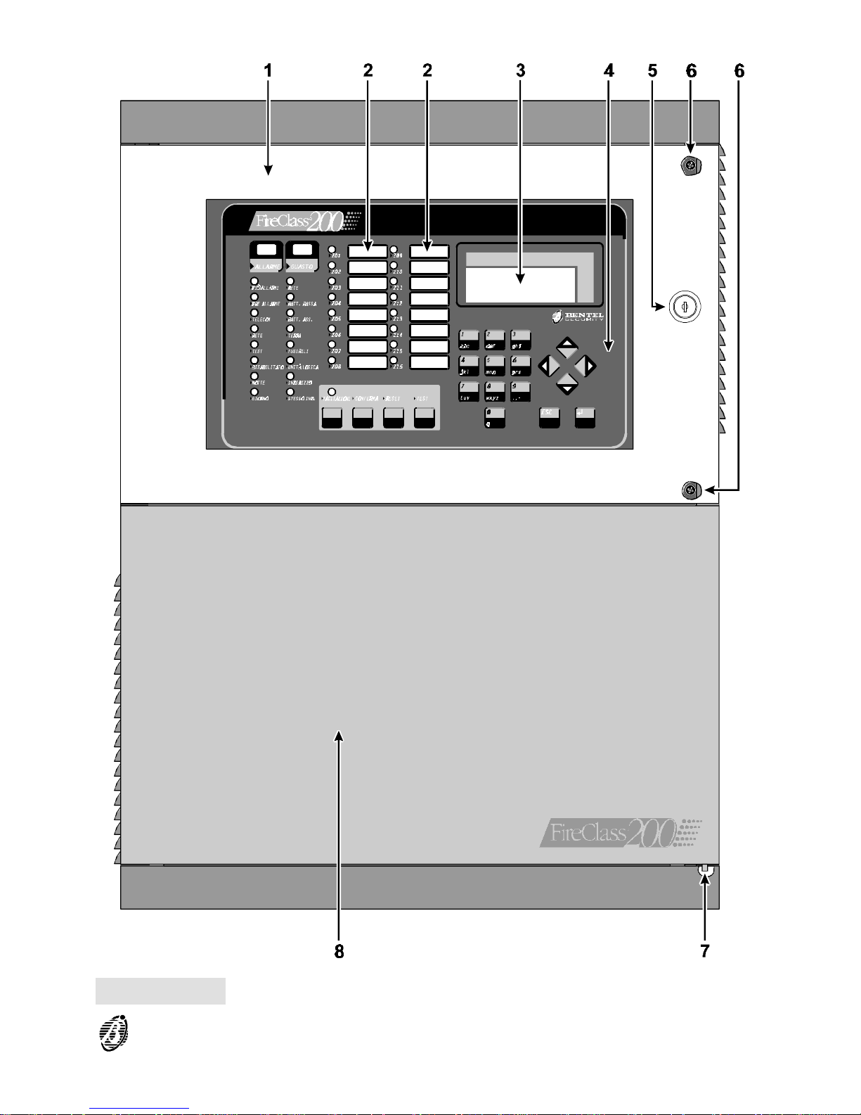
Figure 2 Main unit parts (external)
PARTS IDENTIFICATION 13
Page 14

PART DESCRIPTION
9
Jumper to enable programming:
> programming enabled (default)
> programming disabled
10 Keypad/Display board
11
Cable passage (3 x ∅ 30 mm)
12
Wall mounting holes (4 x ∅ 5 mm)
13 6 Output expander FC200/6OUT (optional - 2 maximum)
14 Telecom module FC200/COM (optional)
15 Main board
16 27.6 V - 4 A linear power supply/battery charger
17 27.6 V - 2.5 A switching power supply/battery charger
18 Battery connectors
19 Compartment for two (optional)12 V, 17 Ah batteries
20 Jumper for series connection of batteries
21
Bag holding: two F 250V 3.15A fuses; one F 250V 6.3A fuse; two keys;
four 1N4007 diodes; jumper for series connection of batteries
22 Chased cable passage (40 x 170 mm)
23 Loop interface
14 Analogue Fire Control Panel FireClass200
Page 15
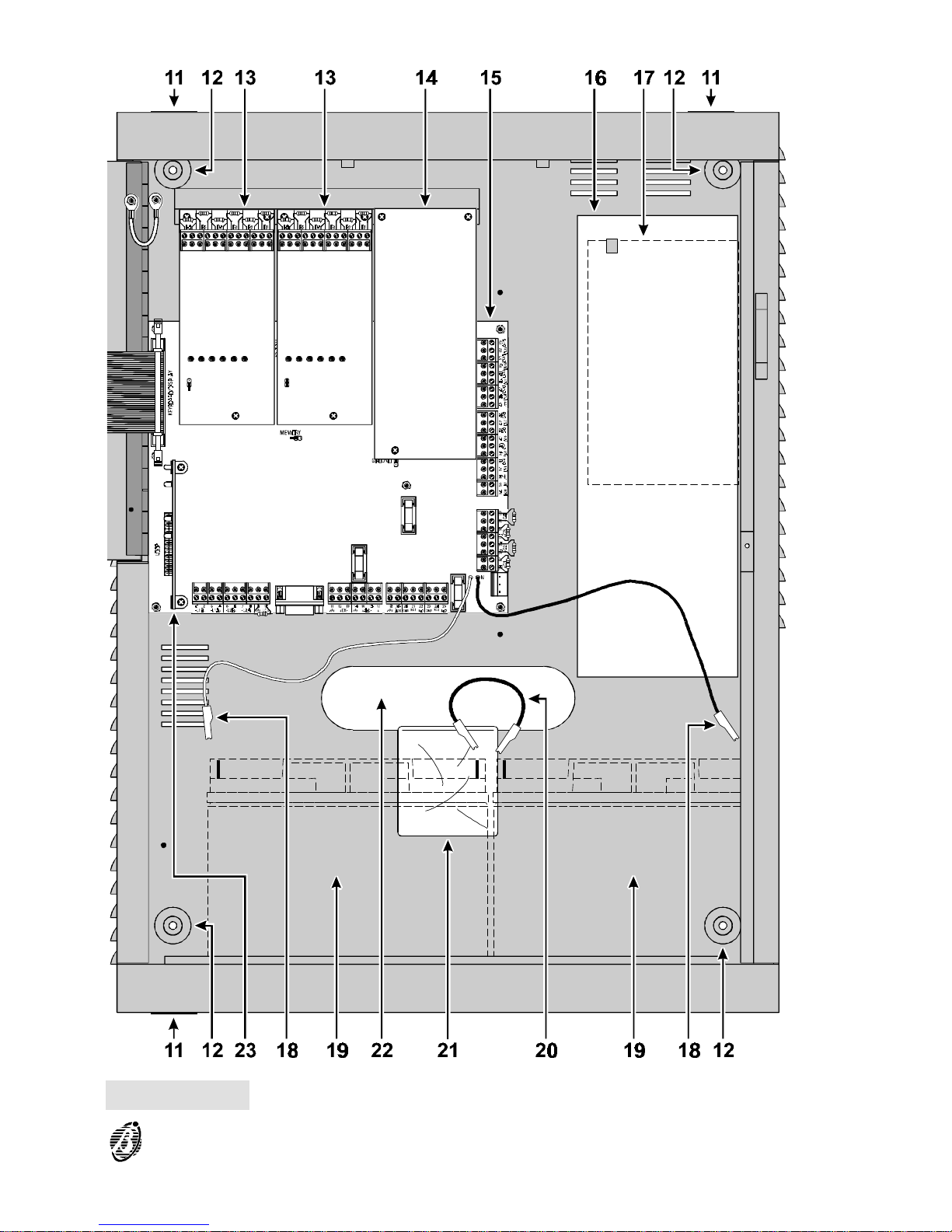
Figure 3 Main unit parts (internal)
PARTS IDENTIFICATION 15
Page 16
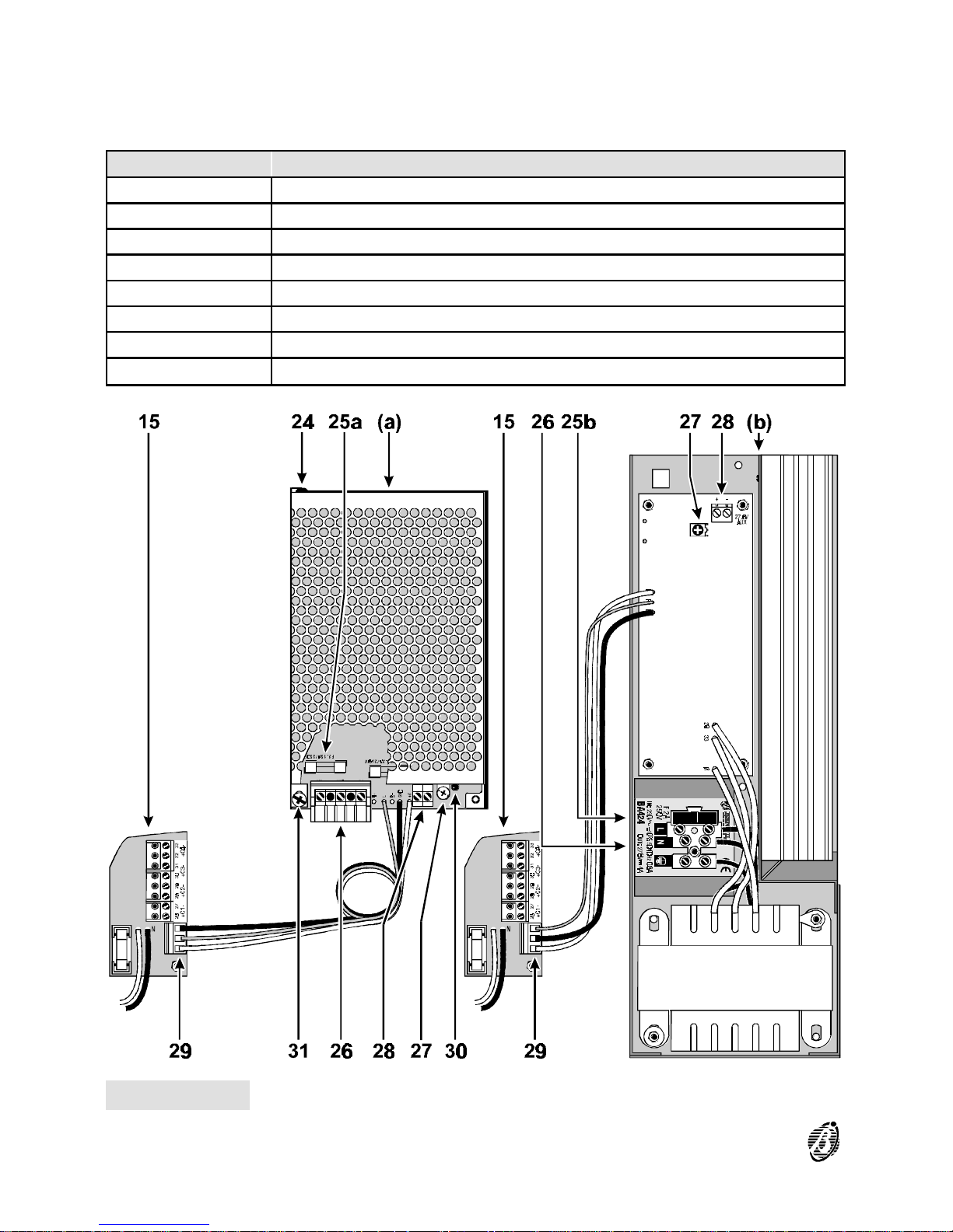
Power unit The FireClass200 is available in two models: FC200/S - with 27.6 V - 2.5 A
Switching power supply (see fig. 3a); FC200 - with 27.6 V - 4 A Linear
power supply (see fig. 3b).
PART DESCRIPTION
24 Rivet to secure switching power supply
25 Power supply protection fuse: a) F3.15A 250V; b) F 2A 250V
26 Terminal board for Mains power connection
27 Fine adjustment trimmer for output voltage
28 Power supply output for devices operating at 24 V (27.6 V)
29 Connector for power supply to the main board
30 Switching-power-supply output voltage signal
31 Screws to secure Switching power supply
Figure 4 Parts of the Power Supply Unit
16 Analogue Fire Control Panel FireClass200
Page 17

PART DESCRIPTION
32 Connector for Keypad/Display
33 Connectors (2) FC200/6OUT Output expanders
34
Jumper to enable data storage:
> memory disabled (default)
> memory enabled
35 Microprocessor
36 Connector for FC200/COM Telecom module
37 Reserved jumper
38 Extractable terminal boards
39 EOL Resistor (2.700 ohm / red-purple-red-gold)
40 Power-supply connector
41 F 6.3A 250V protection fuse against battery polarity inversion
42 F 3.15A 250V protection fuse for +AUX output
43 F 3.15A 250V protection fuse for the power supply line of the RS458 bus
44 RS232 Serial Port
45 Loop interface connector
Figure 5 Main board parts
PARTS IDENTIFICATION 17
Page 18

Output Expander (FC200/6OUT)
PART DESCRIPTION
46
Output status:
LED OFF > corresponding Output in standby status
LED ON > corresponding Output active
47
Address assignment jumper:
> Expander of Output no. 1 (Outputs no. 5 through no. 10)
> Expander of Output no. 2 (Outputs no. 11 through no. 16)
Loop Interface
PART DESCRIPTION
48 Loop 2 Status: polling (Red LED)
49 Loop 2 Status: response (Green LED)
50 Loop 1 Status: polling (Red LED)
51 Loop 1 Status: response (Green LED)
Figure 6 Parts of the FC200/6OUT Output Expander (a) and Loop Interface (b) and
Telecom module (c)
18 Analogue Fire Control Panel FireClass200
Page 19

Telecom Module FC200/COM
PARTS DESCRIPTION
52 Main board connector
53 Microphone
54 Loudspeaker connector
55 Terminal board for telephone line connections
56 Screws for backplate
57
Earth cable with eyelet terminal ---- to be fixed to the screw on the
backplate, and connected to the earth terminal of the Telecom Module
58
Cable and connector for connecting the loudspeaker to the Telecom
Module
59
Plastic (ABS) gaskets to be used when mounting the loudspeaker to the
backplate
60 Loudspeaker
Figure 7 Parts of Telecom Module.
PARTS IDENTIFICATION 19
Page 20

Repeater
PART DESCRIPTION
61
Wall mounting holes (3) for (∅ 5 mm)
62
Cable duct holes (2) for (∅ 30 mm)
63 Microprocessor
64 Address assignment switches
Figure 8 Repeater parts
20 Analogue Fire Control Panel FireClass200
Page 21

INSTALLATION
ATTENTION Installation of the FireClass200 must be carried out in
strict accordance with the instructions herein and in compliance with
the local laws and bylaws in force.
Work carefully through the following steps (refer to the figures on pages 11
and 13).
Ø Plan the system layout.
Ø Lay the cables.
Ø Mount the control panel.
Ø Install add-on boards (if necessary).
Ø Complete the connections.
WARNING: DO NOT connect the Mains until all other wiring has been
completed.
Ø Program the control panel parameters.
Ø Test the system (detectors, signalling and ancillary devices).
Mounting the Control panel
When selecting the mounting location, ensure that:
Ø the Mains power, peripherals and the telephone line can be connected to
the control panel without difficulty;
Ø there is at least 20 cm space on all sides of the control panel to allow for
air flow.
Work carefully through the following steps.
1. Open the control panel door 1: pull the plastic bag 21 through the wire en-
try 22 (the control panel key is inside the plastic bag).
2. Remove the screws 6 and the control panel frontplate.
3. Lift the battery-housing door off its hinge 7 and open the door.
4. Drill the anchor screw holes 12 (use the backplate for the screw locations).
CAUTION Check for water pipes and cable conduits before drilling.
5. Pull the chased wires through the wire entry 22 and attach the control
panel to the wall.
INSTALLATION 21
Page 22

6. Using a hammer, remove the knockout and pull the external wires through
the wire entry 11.
+
Use HB flame class (or higher) lock nuts to secure the cable conduit union to the box.
Installing Output expanders (FC200/6OUT)
Work carefully through the following steps (refer to the figures on pages 11
and 12).
1. Insert the Output Expander into the respective connector (33 or 34).
2. Using the screws and gaskets (supplied), secure the Output Expander in
place (use the longer screw for the lower part, and the two shorter screws
for the upper part).
3. Using the jumper 47, assign an address to the Output Expander (refer to
the following chart).
JUMPER
47
OUTPUT
EXPANDER No.
CORRESPONDING OUTPUT
C5/11 C6/12 C7/13 C8/14 C9/15 C10/16
1 05 06 07 08 09 10
2 11 12 13 14 15 16
+
You must assign a different address to each output expander.
Installing the Telecom Module (FC200/COM)
Work carefully through the following steps (refer to the figures on pages 17
and 18).
1. Insert the Telecom module into the respective connector 36.
2. Using the screws and gaskets (supplied), secure the Telecom module in
place (use the longer screw and gasket for the lower part, and the two
shorter screws for the upper part).
Installing Repeater Panels (FC200/REP)
Work carefully through the following steps (refer to the figure on page 13).
1. Drill the anchor screw holes 52 (use the backplate for the screw locations).
2. Pull the wires through the wire entry 53 then attach the repeater panel to
the wall.
3. Complete the connections on the terminal board 38.
22 Analogue Fire Control Panel FireClass200
Page 23

4. Using the microswitches 55, assign an address to the repeater panel (refer
to the following chart).
MICROSWITCH No.
ADDRESS No. 1 2 3 4
1 OFF OFF OFF OFF
2 ON OFF OFF OFF
3 OFF ON OFF OFF
4 ON ON OFF OFF
5 OFF OFF ON OFF
6 ON OFF ON OFF
7 OFF ON ON OFF
8 ON ON ON OFF
+
You must assign a different address to each repeater panel.
Completing the Connections
+
Use a shielded cable ---- connect one end to the control panel ground and
leave the other floating.
CAUTION Separate the low voltage wires (24V) from the high voltage
wires and make two wire bunches. This will prevent stray wires from
coming into contact with other wires and/or components.
Main board terminals
[L1B] Loop 1 communication IN.
[L1A] Loop 1 communication OUT.
[L2B] Loop 2 communication IN.
[L2A] Loop 2 communication OUT.
+
Each loop supports 99 analogue detectors and 99 analogue devices (Input
modules, Conventional Zone modules, Manual callpoints, Output modules
and Sounders).
[LC] Conventional Input Line - Supervised and Silenceable ---- This line sup-
ports 30 conventional fire devices (RF501t Optic Smoke detectors, RT
101/102 Heat detectors, Manual callpoints, Gas detectors----maximum 3).
Connect terminal 10[+] to ground (terminal 9[ ]) using a 2,700 ohm resistor
(red-purple-red-gold). A 680 ohm resistance (normal value for Fire detectors)
parallel to the 2,700 ohm resistor will activate the programmed actions and
preset times of the Conventional Line outputs and the Non-supervised output
(terminals CM1, NC1 and NO1).
INSTALLATION 23
Page 24

+
The Conventional Line supports 30 Conventional detectors.
WARNING Do not connect more than 512 devices to the control panel.
[EX] Reserved Output.
[485] Serial Bus ---- Terminals for FC200/REP repeater panels (maximum 8)
and FireClass200 Slave panels (maximum 7).
Serial bus terminals ---- 15[+] and 16[-];
27.6 V power voltage terminals ---- 14[ ] and 17[+].
[AUX] Aancilliary power 24 V ---- Power supply to devices that operate at 24 V
(protected by fuse 42 and powered by the standby batteries):
Ø Positive (27.6 V) on terminal 19[+];
Ø Ground on terminal [ ].
[CM1]
[NC1]
[NO1]
Non-supervised fault output ---- Dry contact relay for non-supervised devices:
Ø During standby status ---- terminal 20[CM1] closes to terminal 21[NC1];
Ø In the event of fault ---- terminal 20[CM1] closes to terminal 22[NO1].
+
Blackout events (mains and battery supply failure) will activate the Non-supervised fault output.
[CM2]
[NC2]
[NO2]
Non-supervised fire output ---- Dry contact relay for non-supervised devices:
Ø During standby status ---- terminal 23[CM2] closes to terminal 24[NC2];
Ø In the event of fire ---- terminal 23[CM2] closes to terminal 25[NO2].
[C] Type C output - Supervised ---- Terminals for supervised devices acti-
vated by positive (24 V):
Ø During ALARM status ---- positive (27.6 V) on terminal [+]; ground on terminal [-].
Ø This output can be bypassed via the DISABLE menu.
+
ALARM status will activate this non-programmable output.
[C2] [C3] [C4] Positive outputs - Programmable - Supervised ---- Terminals for super-
vised devices activated by positive (24 V):
Ø Output active ---- positive (27.6 V) on terminal [+]; ground on terminal [--].
Ø These outputs can be bypassed via the DISABLE menu.
Connect an EOL 2,700 ohm resistor (red-purple-red-gold) to terminals [+]
and [--] of these outputs. This will allow the control panel to detect and signal when the outputs are shorted and/or open.
NOTE: The EOL resistor must be connected to the last device on the Su-
pervised output.
Connect a diode (1N4002 or 1N4007) in series to the devices connected to
these outputs.
24 Analogue Fire Control Panel FireClass200
Page 25

+
All the [+] terminals of the Supervised outputs must be closed to the [--] terminal of the same output. For for example, the connection on terminal
26[+] must close only to terminal 27[--].
[REM] Logic Unit Blocked ---- Output for remote signalling of the Logic Unit
Blocked fault:
Ø During Blocked fault ---- positive (27.6 V) on terminal 34[REM].
+
An external power supply must be used to supply the devices connected to
the REM output.
[DEF] Default programming ---- This output will indicate when the control panel
is operating with default programming values:
Ø Default programming values ---- Negative on terminal 35[DEF] (if the
control panel is operating with default programming).
[OC1] ... [O16] Bypassable Zone Alarm outputs ---- These are normally-open terminals
(open-collector) which close to ground when the corresponding zones go into
alarm status. These terminals will remain closed to ground even after the generating event has ended. These are non-supervised/non-silenceable outputs
which can be forced to standby by bypassing the zone concerned or rearming
the control panel.
These terminals can be used for selective fire-prevention operations (closure of fire-barrier doors; activation of localized extinguishment systems).
+
The Zone Alarm outputs will not activate if their associated zones are
disabled, however, they will activate as soon as their associated
zones are enabled.
INSTALLATION 25
Page 26
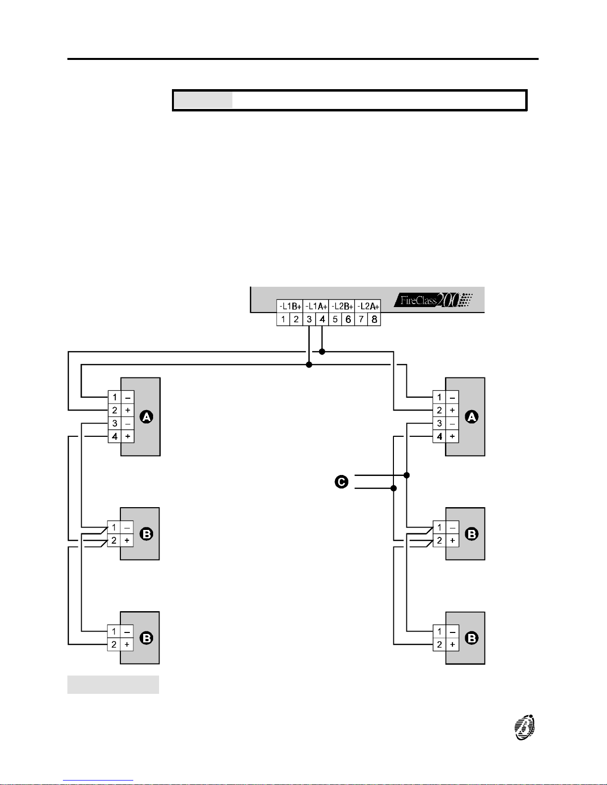
Connectiing Addressable Analogue Devices
The control panel has 2 loops for addressable analogue devices.
WARNING Do not break off the Output module tab.
Each loop supports 99 addressable analogue fire detectors and 99 analogue devices (Input modules, Conventional Zone modules, Output modules, Manual callpoints and Sounders).
Devices of the same type cannot have the same address, therefore, you
must assign a DIFFERENT address to each detector on the loop, and likewise for the modules.
+
Different device types (e.g. Fire detector and module) can have the same
address.
Figure 9 Wiring diagram of a 2 wire connection: a) Insulators; b) Compatible ana-
logue devices (Fire detector, Input modules, Output modules, Conventional
Zone modules, Manual callpoints); c) T connection.
26 Analogue Fire Control Panel FireClass200
Page 27
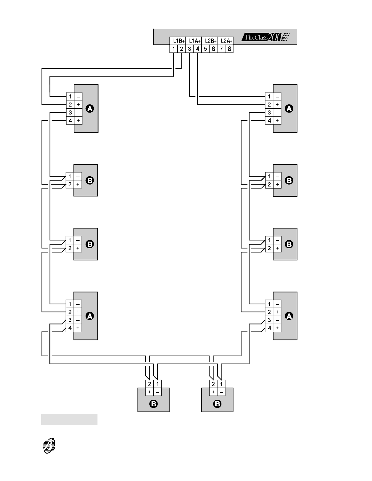
Figure 10 Wiring diagram of a 4 wire connection: a) Insulators; b) Compatible ana-
logue devices (Fire detectors, Input modules, Output modules, Conventional
Zone modules, Manual callpoints).
INSTALLATION 27
Page 28
You can use 2 or 4 wires for the loop connections.
NOTE: The loop connection type must be specified during the programming phase.
Figure 9 illustrates the 2 wire connection to Loop 1.
Figure 10 illustrates the 4 wire connection to Loop 1.
+
The 2 wire connection does not permit more than 32 detectors per loop.
+
The 4 wire connection does not permit T connections.
Connecting Conventional Devices
Connect Conventional devices to terminals 9[ ] and 10[LC+].
Fire detectors Connect the Conventional Fire detectors in parallel to terminals [LC+] and
[ ]. The resistor (2,700 ohm) connected to these terminals must be
moved to the terminals indicated in the instructions of the last device on
the Conventional Line (see fig. 10a).
Manual
callpoints
Connect the Common (C) and the Normally Open (NO) terminals of the
Manual callpoint in parallel to terminals [LC+] and [ ]. When pressed, the
callpoint must not be shorted but must have a 680 ohm resistance. If
the callpoint does not have a 680 ohm resistor, connect one externally. If
the manual callpoint is the last device on the Conventional Line, the EOL
resistor must be connected as per figure 10a.
NOTE: Conventional devices can be connected to the loops by means of
Conventional Zone modules.
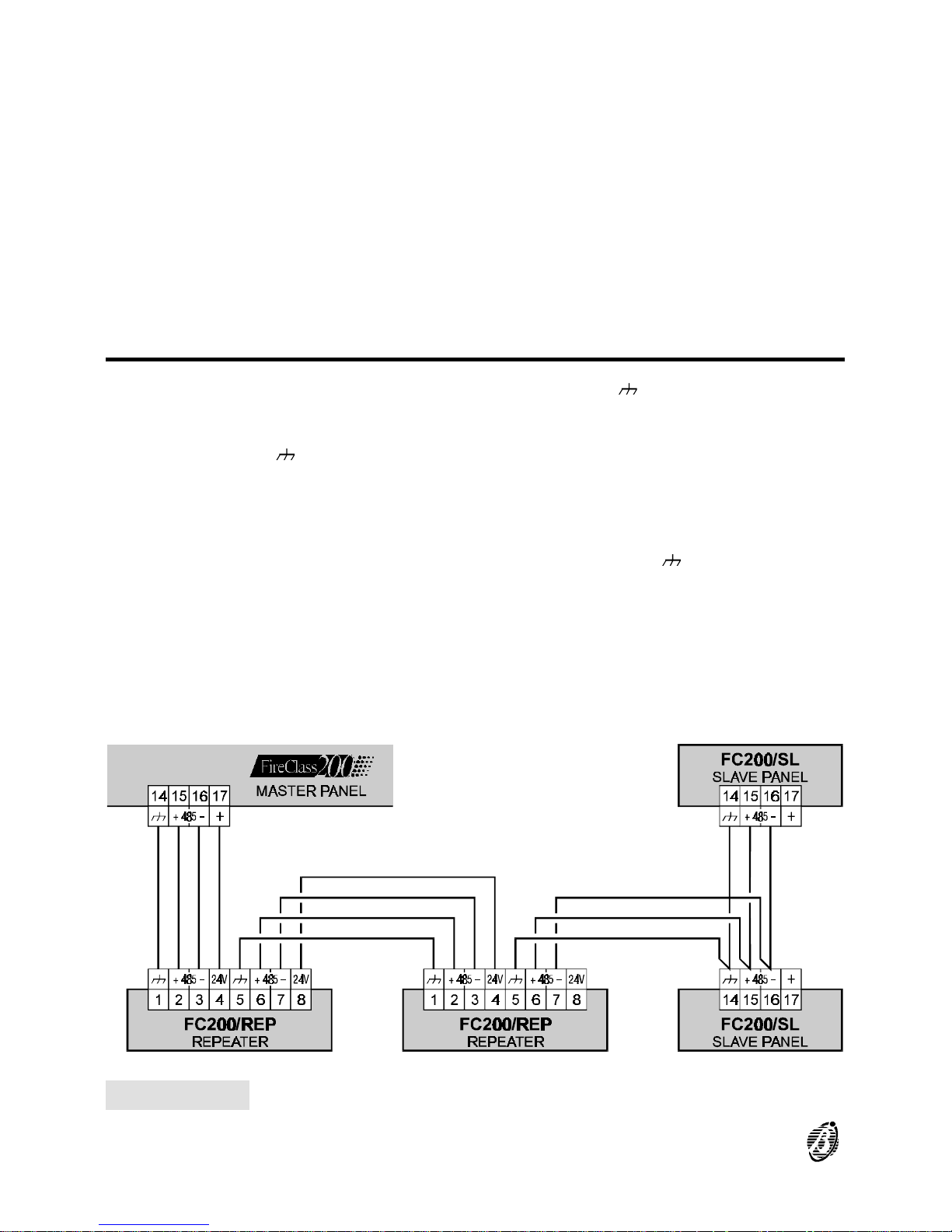
Figure 11 Wiring diagram of Repeater and Slave Panels connected to the RS485 network
28 Analogue Fire Control Panel FireClass200
Page 29

Connecting Repeaters and Slave Panels
The RS485 port of the FireClass200 (terminals 15[+485] and 16[--485]) accepts up to 8 FC200/REP repeater panels and 7 FC200/SL slave panels.
Terminals 17[+] and 14[ ] supply the power (27.6 V) to the repeater panels.
The FireClass200 must be programmed as Master, otherwise, it will be unable to communicate with the system repeater panels and/or slave panels.
Assigning addresses
Using the Network option from the System Menu, assign a different address to each slave panel
Figure 12 Wiring diagram of Conventional device connections
INSTALLATION 29
Page 30
Connecting Output Devices
The control panel has 2 Non-supervised outputs, 4 Bell outputs (supervised) and 8 Alarm Repeat outputs (one for each Software zone).
The control panel can manage two FC200/6OUT Output Expanders (accessory items) which provide 6 Bell outputs each.
NOTE: Output devices can be connected to the loops by means of Output
modules.
Bell Outputs
The Bell outputs are indicated by the letter "C" and their address number.
You can fully customize the activation modes and times of the Bell outputs.
+
The address of the Output-Expander Bell outputs depends on the OutputExpander address.
+
The terminal marked "C" is a Type C Output and not a Bell output.
The Type C Output is a Non-programmable, Supervised output.
The Bell outputs can be forced to standby status by means of the SILENCE button. Once an alarm has been acknowledged, you can silence
the audible signalling devices and leave the visual signalling devices active
until the alarm conditions cease.
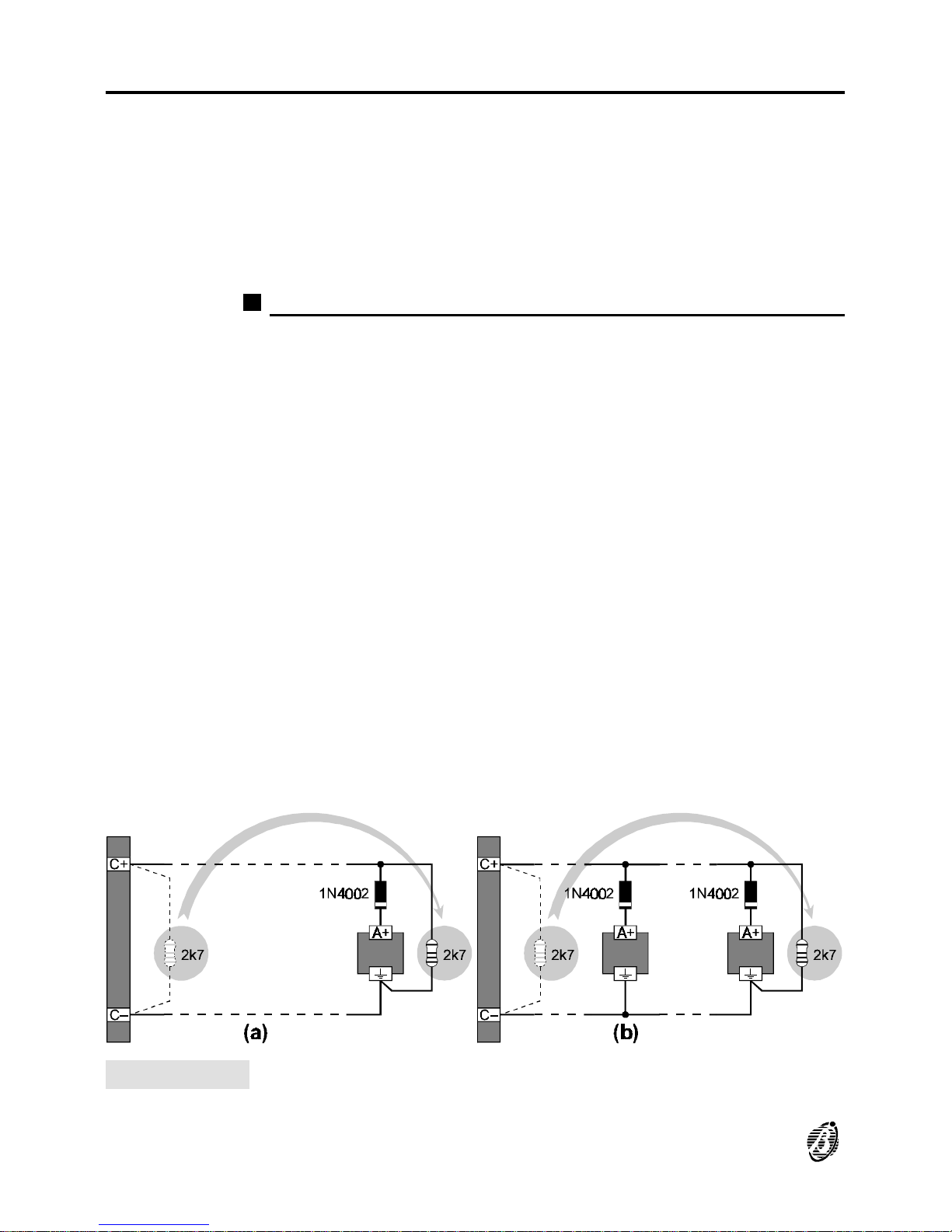
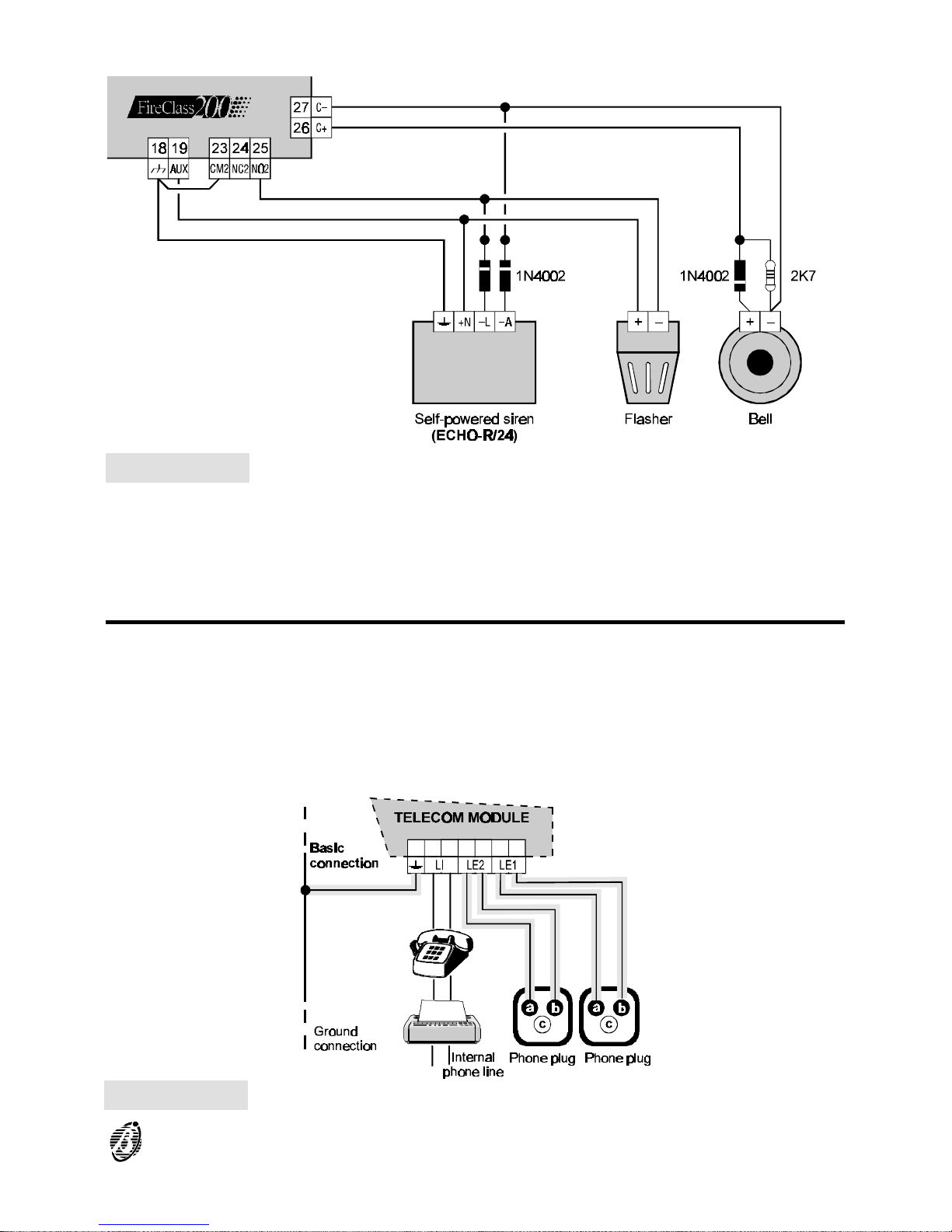
For example, a connection similar to the wiring diagram in figure 14 will activate the Flasher, the Bell and the visual and audible signalling device of
the Self-powered Siren in the event of an alarm.
Using the SILENCE button will stop the horn but not the flasher, which will
continue to signal Alarm status until the RESET button is pressed.
Figure 13 Wiring diagram of the connection of a single device (a) and several devices
(b) to Bell outputs (device activated by positive (27.6 V) on terminal [A+]).
30 Analogue Fire Control Panel FireClass200
Page 31
Connecting the Telecom Module (FC200/COM)
Figure 14 Wiring diagram: NON-silenceable and Silenceable Output connections
Figure 15 Wiring diagram of the Telecom module connections
INSTALLATION 31
Page 32
Connecting the Power Supply
The power systems of this control panel conform with EN54-4.
IMPORTANT Connect the Panel to a Mains power supply that com-
plies with the required specifications (see label). DO NOT powerup the
Panel with a voltage different to requirements.
Ø Connect the external power supply to terminal 26: connect Earth to terminal
[ ]; Neutral to terminal [N] and Line to terminal [L].
Ø Fit the two 12 V - 17 Ah batteries; connect in series to the jumper 20 (sup-
plied); connect the dry contacts to the connector 18.
Ø Insert the jumper 34.
IMPORTANT In compliance with safety regulations, the Line must be
connected to terminal [L] and the Earth to terminal [ ]. An automatic
isolating switch must be fitted to protect against overvoltage and shortcircuit.
+
The control panel will rearm automatically when power restores after blackout.
+
Use YASA 12 V - 17 Ah batteries - model NP 17-12 FR, or similar, with
UL94-V2 (or over) case flame class.
+
Respect the connection polarity. In the event of inverted polarity, replace
the fuse 41 (F 6.3A 250V).
+
The display configuration on power-up depends on the operations done
prior to power failure.
Ø No parameters changes prior to power failure will be indicated by the green
NETWORK LED (ON) and the following messages (shown intermittently).
From this status you can access the system by pressing any key except
TEST.
FIRE CLASS 2ØØ
No Devices
Default Data
ØØ:ØØ 23/11/98 Mon
FIRE CLASS 2ØØ
Hit a Key
to take
control
32 Analogue Fire Control Panel FireClass200
Page 33

Ø If parameter changes were made prior to power loss, the following mes-
sages will be shown intermittently.
From this status it will be possible to access control panel management by
pressing any button except RESET and TEST.
Ø If autolearning was done prior to power loss, the following message will be
shown.
From this status it will be possible to access control panel management by
pressing any button except RESET and TEST.
Maintenance
Carry out the following operations periodically.
1. Remove dust with a damp cloth (use water only).
2. Clean the Plexiglas window with a damp cloth (use water only). Do not
clean the control panel keypad, as you may accidentally activate a
command.
3. Press the TEST button to check the LEDs and the Buzzer.
4. Check the batteries.
5. Check all connections.
6. Check that the inside of the control panel cabinet is free from obstructions.
+
Steps 4., 5. and 6. must be carried out by qualified persons only.
FIRE CLASS 2ØØ
No Devices
acquired
ØØ:ØØ 23/11/98 Mon
FIRE CLASS 2ØØ
Hit a Key
to take
control
FIRE CLASS 2ØØ
Scanning Loop
>> >> >>
ØØ:ØØ 23/11/98 Mon
INSTALLATION 33
Page 34

34 Analogue Fire Control Panel FireClass200
Page 35

USING THE SYSTEM
The FireClass200 system can be managed from the main panel, over-thephone (via a Telecom interface) and/or through the FC200/SW software
application (the computer must be connected locally via RS232 serial port).
The locked cabinet door allows access to authorized key holders only (Access Level 2A).
There are three main phases with different access levels, as follows.
Programming The Programming phase allows the installer to program the control panel
and peripheral devices (detectors, modules, repeater and slave panels).
Access to this phase requires entry of the Installer PIN (Access Level 3A).
Modifying The Modifying phase allows users to disable the control panel peripherals
and delete (clear) the counters and memory. Access to this phase requires
entry of the Installer PIN or a User PIN (Access Level 2B).
Reading
Parameter
The Reading Parameter phase allows users to:
---- view and/or print the control panel log (events and programming data);
---- check the control panel and peripheral device parameters;
---- view the control panel version.
No PIN is required.
+
The instructions herein refer to system management from the Control
panel. For the instructions relative to programming and management
from a PC refer to the FC200/SW software instructions manual.
The parameter descriptions and values are valid in both cases.
Operating the system
Read this section carefully to get an overall view of the steps involved in
using the FireClass200 system.
Alphanumeric
keypad
Use the keypad to select the menu options, create labels and enter data
and codes.
Cursor keys
Use the ← and → keys to scroll the parameters, and the ↑ and ↓ keys to
select new values.
ESC] Use the ESC key to exit menus and windows and step back.
+
The ESC key usually exits windows without changing the data, however,
changes made in the device parameter windows will be saved.
USING THE SYSTEM 35
Page 36

↵ Use the ↵ key to confirm and save changes and to step forward or back.
Editing a Text Read this section carefully to get an overall view of the steps involved in
creating strings (e.g. Labels).
Ø Use the ← and → keys to scroll along the line.
Ø Press the respective key until the required letter is shown.
Ø Use the ↑ key for upper-case letters and the ↓ key for lower-case letters.
Ø Use key 9 for punctuation marks (full-stop, comma and dash) and spaces.
Once the text has been completed, press the ↵ key to confirm and step forward, or position the cursor on the first letter of the text then press the ←
key to step back.
# The display examples show the default values (refer to Analogue values).
The # symbol indicates that the respective parameter has no default value
setting.
36 Analogue Fire Control Panel FireClass200
Page 37
Accessing the system
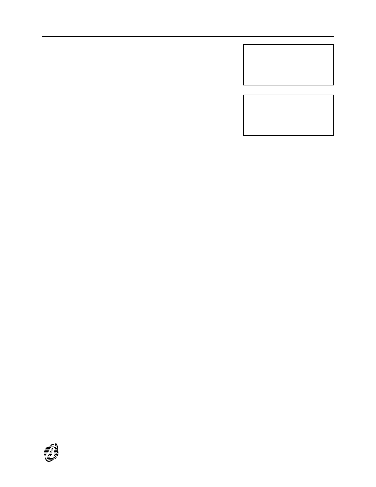
Press any key, except RESET and TEST,
to access the FireClass200 system.
The display will show the MAIN menu.
Select the required option, and refer to the respective section.
Exit If no key is pressed within 20 seconds, the control panel will exit automat-
ically.
FIRE CLASS 2ØØ
Scanning Loop
>> >> >>
ØØ:ØØ 23/11/98 Mon
FIRE CLASS 2ØØ
1= Programming
2= Modifying
3= Reading Parameter
USING THE SYSTEM 37
Page 38

38 Analogue Fire Control Panel FireClass200
Page 39
PROGRAMMING
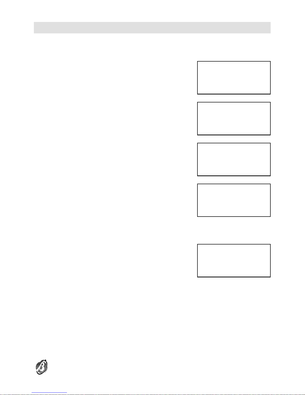
Press 1 to access the PROGRAMMING
menu from the MAIN menu.
Type in the installer code (00000 at default). Each digit will be masked by the
symbol Q.
Press the ↵ key to confirm the code.
The display will show the PROGRAM-
MING menu.
Select the required option and refer to the
respective section for instructions.
Wrong code If you enter a wrong code, the system will
prompt you to Retry.
Default Installer
code
To change the installer code (00000 at default), refer to the "Password
(PassWD)" section.
RAM disabled If the jumper 9 is not connected the dis-
play will show the RAM Disabled message.
FIRE CLASS 2ØØ
1= Programming
2= Modifying
3= Reading Parameter
Enter
installer
code
*****
1=Auto 2=Devices
3=PassWD 4=MesINI
5=Zones 6=Opt 7=Sys
8=Ver 9=Def Ø=Tel
Installer code
wrong !
Retry
XXXXX
Writing
RAM
Disabled !
Act on internal DIP
PROGRAMMING 39
Page 40
Auto (Autolearning - Automatic enrolling)
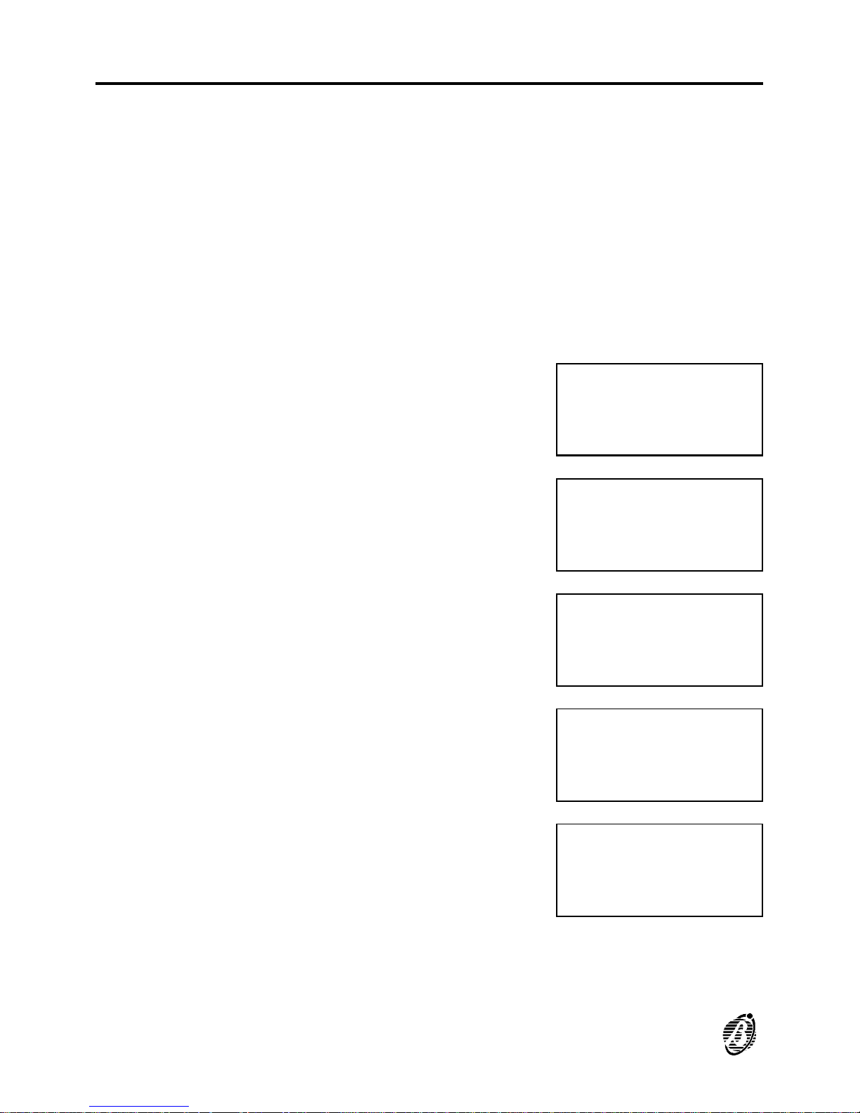
The Auto option from the PROGRAMMING menu will allow you to enrol
the loop devices and the RS485 network devices automatically.
+
Autolearning (enrolling) must be done during the installation phase and after changes to the loop and network configurations, bell outputs and Telecom module.
+
Ensure that the SAME ADDRESS LED is OFF before starting.
Ø Select the Network option from the SYSTEM menu then configure the
FireClass200 as the Master panel. Otherwise, the Master panel will be unable to communicate with the system repeater and slave panels).
Ø Auto-learning does not modify the programmed parameters.
1. Select the Auto option from the PRO-
GRAMMING menu (press 1).
2. The control panel will search Loop 1 ...
3. then Loop 2 ...
4. and finally the RS485 network.
5a. When the Auto-learning phase ends on a
SLAVE panel, the display will show ...
1=Auto 2=Devices
3=PassWD 4=MesINI
5=Zones 6=Opt 7=Sys
8=Ver 9=Def Ø=Tel
Autolearning
searching on:
LOOP 1
please wait....
Autolearning
searching on:
LOOP 2
please wait....
Autolearning
searching on:
NET
please wait....
Analysis connections
1)LOOP 1
2)LOOP 2
3)NET not supported
40 Analogue Fire Control Panel FireClass200
Page 41
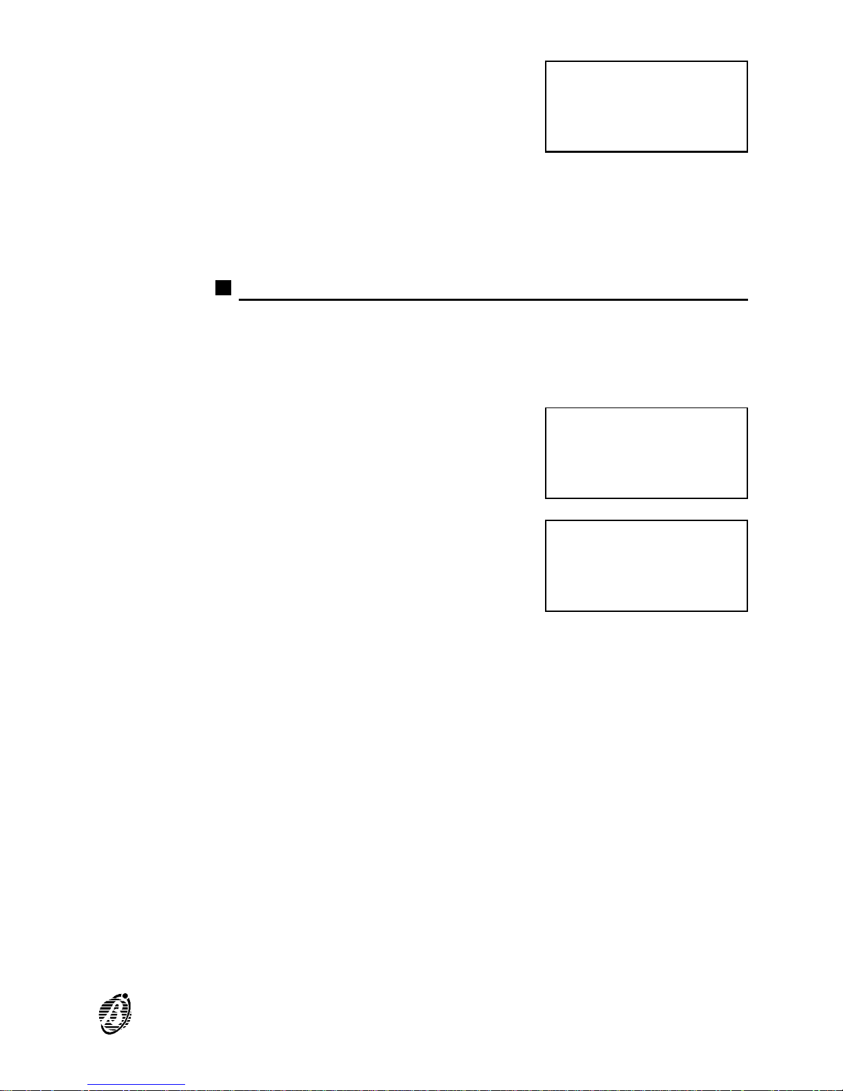
5b. If the control panel is programmed as
MASTER, the display will show ...
Select the required loop (1 or 2) to access and program the parameters of
the loop devices. Refer to the "Connections: Loop 1 and Loop 2" section.
Select 3 to access and program the parameters of the RS485 network devices of the MASTER panel (refer to "Network Devices").
Connections: Loop 1 and Loop 2
+
The following instructions apply to loops 1 and 2.
+
The example shows loop 1 with two optical smoke detectors at addresses
1 and 2.
1. Select the Loop 1 option from the ANALY-
SIS CONNECTIONS menu (press 1) and
program the loop 1 device parameters.
2. The display will show the loop 1 devices.
Smoke This shows the number of smoke detectors.
Temperature This shows the number of heat detectors.
Mod.IN This shows the number of input modules (IN).
Mod.OUT This shows the number of output modules (OUT).
Balanced
Outputs
This shows the number of bell outputs:
without Output Expander = 4 bell outputs;
with 1 Output Expander = 10 bell outputs;
with 2 Output Expanders = 16 bell outputs.
+
Use the Devices option from the PROGRAMMING menu to program the
Bell Outputs.
Analysis connections
1)LOOP 1
2)LOOP 2
3)NET
Analysis connections
1)LOOP 1
2)LOOP 2
3)NET
Loop 1 devices:
Smoke :## Thermal:##
Mod.IN:## Mod.OUT:##
Balanced outputs :##
PROGRAMMING 41
Page 42
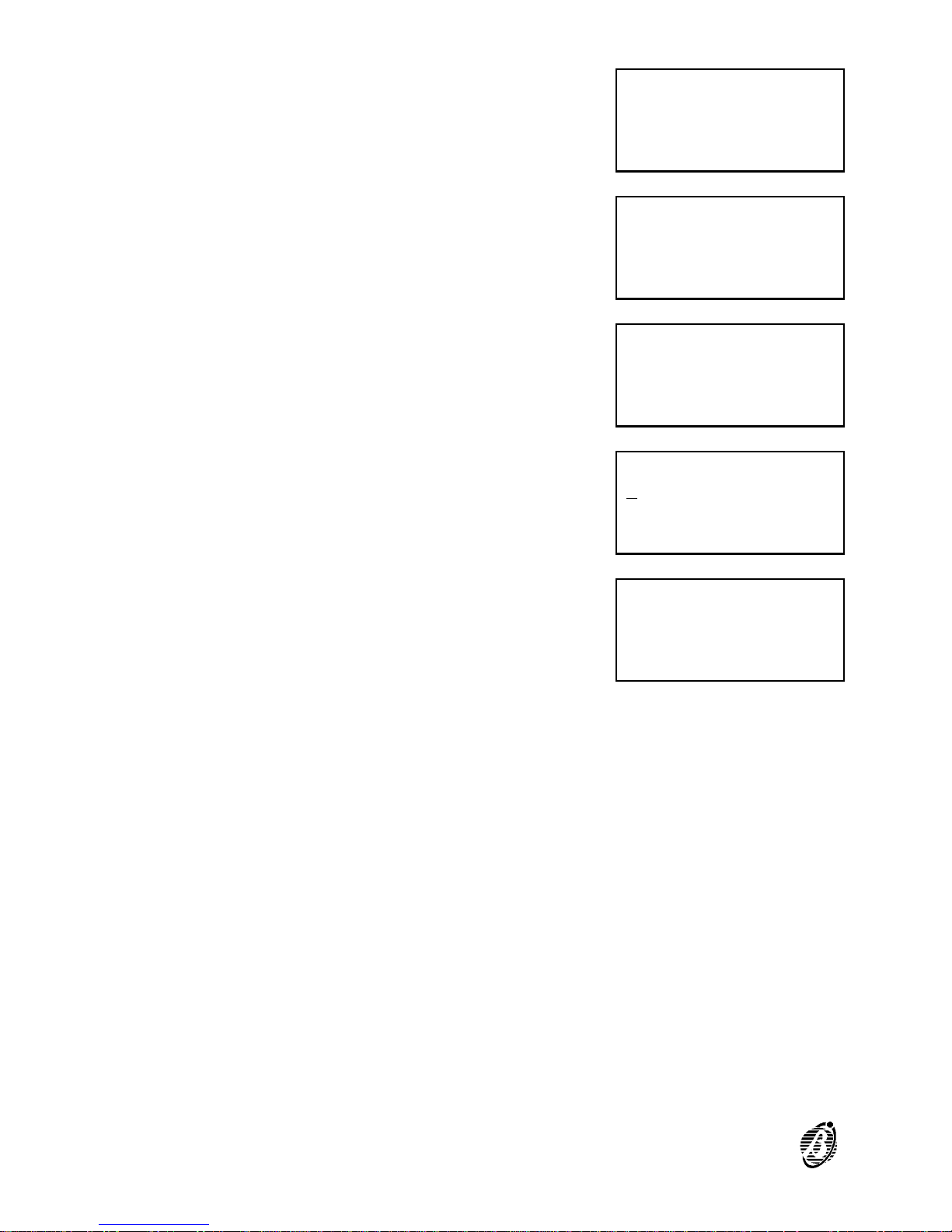
3.
Press the ↵ key to view the parameters of
the devices at the lowest address. If several devices share the same address, detectors will be shown first.
4. Position the cursor on the last parameter
on the bottom right then press the ↵ key.
5. The display will show the parameters of
the device at the next address.
6. Position the cursor on the first character of
the second line then press the ← key.
7. The display will show the parameters of
the device at the previous address.
8. Press ESC to step back to the CONNECTIONS menu (step 1.).
PRG:Smoke (Optic)%##
Device: SENSOR
Z=ØØ Z=ØØ Z=ØØ Z=ØØ
AT=5Ø **V=ØØ ** 1/Ø1
PRG:Smoke (Optic)%##
Device: SENSOR
Z=ØØ Z=ØØ Z=ØØ Z=ØØ
AT=5Ø **V=ØØ ** 1/Ø1
PRG:Smoke (Optic)%##
Device: SENSOR
Z=ØØ Z=ØØ Z=ØØ Z=ØØ
AT=5Ø **V=ØØ ** 1/Ø2
PRG:Smoke (Optic)%##
Device: SENSOR
Z=ØØ Z=ØØ Z=ØØ Z=ØØ
AT=5Ø **V=ØØ ** 1/Ø2
PRG:Smoke (Optic)%##
Device: SENSOR
Z=ØØ Z=ØØ Z=ØØ Z=ØØ
AT=5Ø **V=ØØ ** 1/Ø1
42 Analogue Fire Control Panel FireClass200
Page 43
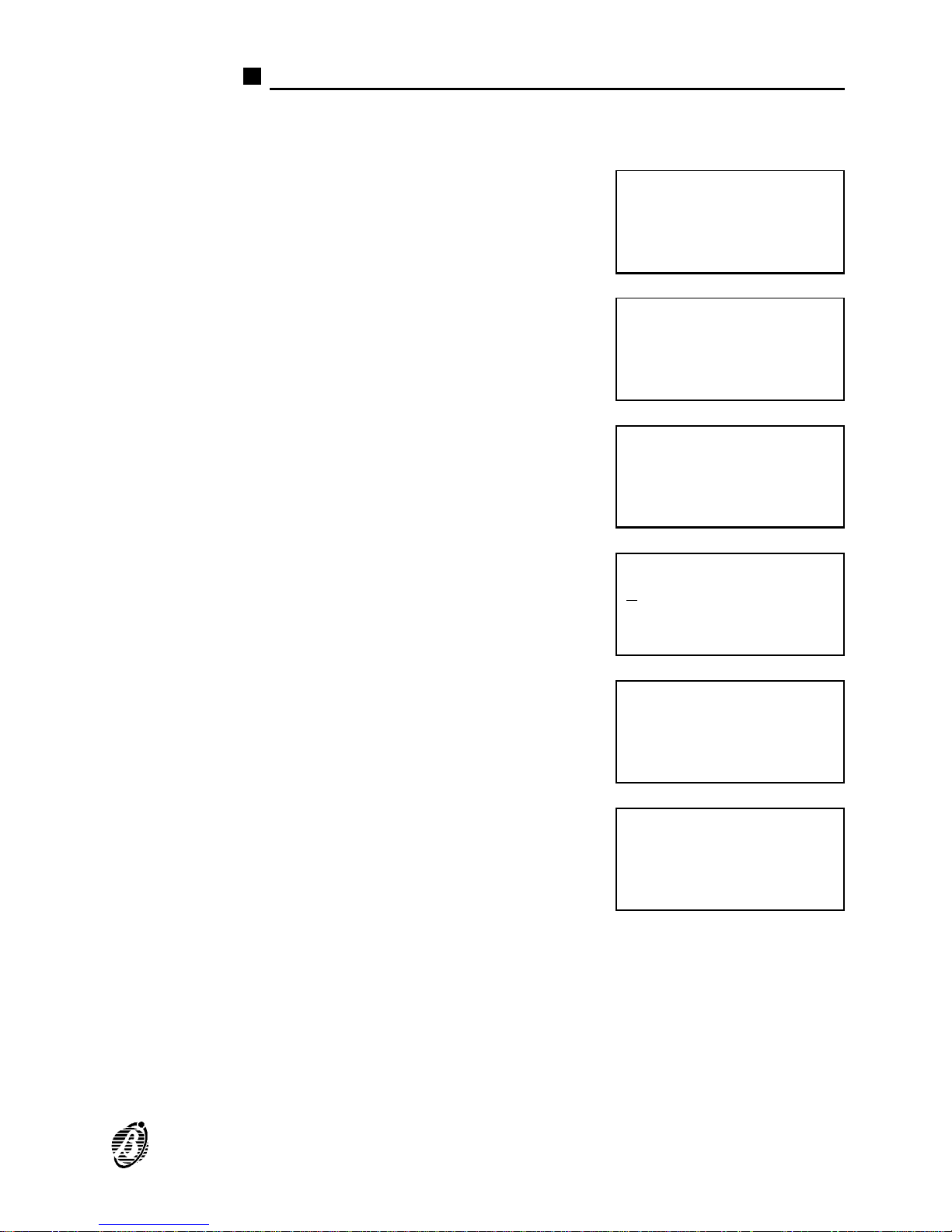
Connections: Network
+
The following example shows two repeater panels, connected to the Network (addresses 1 and 8).
1. Select the Network option from the CON-
NECTIONS menu (press 3) and program
the network device parameters.
2. The display will show the devices found on
the RS485 Network.
3.
Press the ↵ key to view the parameters of
the device with the lowest address. If
several devices share the same address,
repeater panels will be shown first.
4. Position the cursor on the first character of
the second line then press the ← key.
5. The display will show the parameters of
the device at the previous address.
6.
Press the ↵ key to view the parameters of
the device at the next address.
7. Press ESC to step back to the CONNECTIONS menu (step 1.).
Analysis connections
1)LOOP 1
2)LOOP 2
3)NET
NET Devices:
Repeater :#
Slave units:#
Loop Expanders :Ø
PRG:Repeater
Repeater
Address :1
PRG:Repeater
Repeater
Address :1
PRG:Repeater
Repeater
Address :8
PRG:Repeater
Repeater
Address :1
PROGRAMMING 43
Page 44

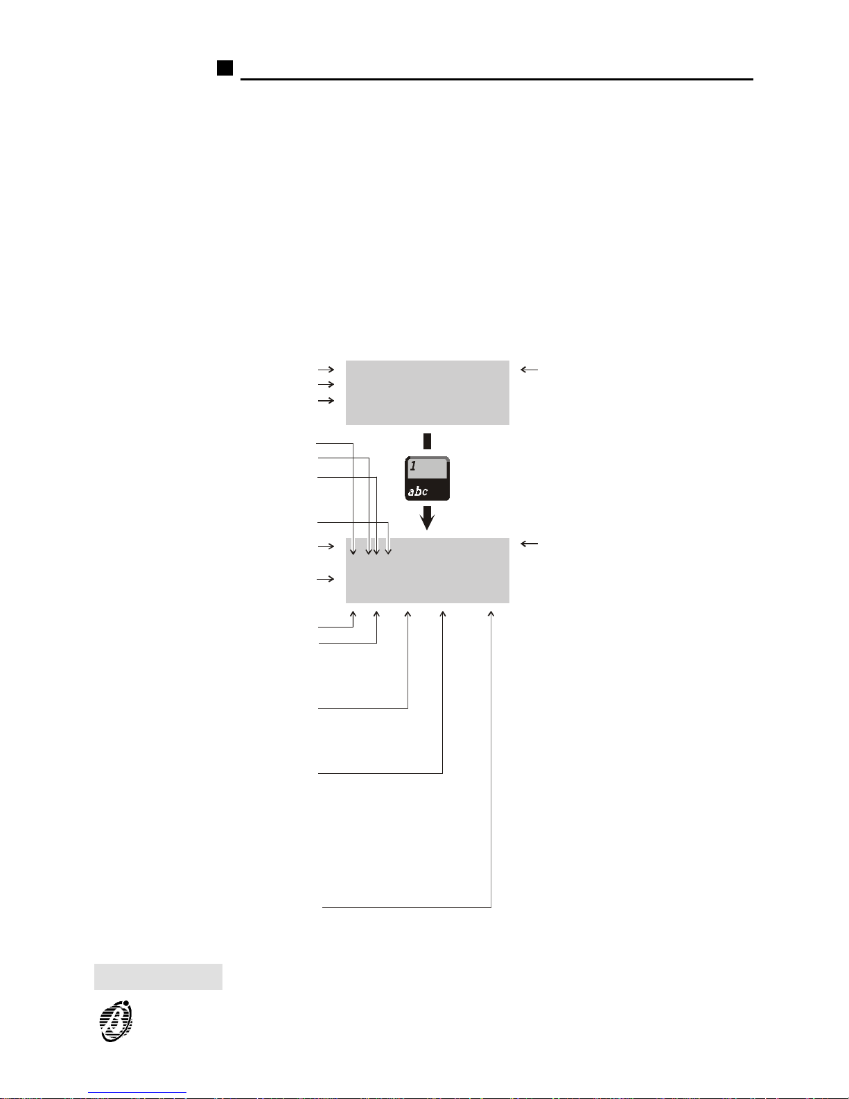
Programming: Fire detectors
Figure 16 shows the fire detector parameters.
Description This is the non-editable description of the device type.
Analogue Value This shows the non-modifiable real-time values measured by the device.
Label This is for the editable device-label (up to 20 characters). The system will
use the label as the device identifier.
Associated Zone Each device can be associated with 4 of the 16 software zones. If a device
goes into ALARM status, all the zones it is connected to (associated
zones) will also go into ALARM status.
Alarm threshold This parameter determines the device threshold, if this limit is exceeded
the control panel will generate ALARM status. The threshold is indicated
by an arbitrary unit: 00 to 99 (default 50%).
Procedure type This determines the actions the control panel will perform when the device
threshold is exceeded:
* (default) - the control panel will signal the ALARM according to the preset
times and operating modes.
P (Prealarm) - the control panel will activate the ALARM delay.
A (Warning) - the control panel will activate a WARNING signal.
Alarm verify This option determines the number of times the device must exceed the
Alarm threshold before the programmed actions will be activated.
If the Alarm verify counter is set at 99, the control panel will not take into
account the number of times the device detects alarm conditions, but will
consider only the length of time the alarm conditions persist. In this way,
the control panel will not generate an alarm until the preset "Alarm verify"
time expires.
Timer The Timer option from the OPTIONS menu will allow you to program the
hours and days of the week when the Alarm threshold must be increased.
It is possible to set T Timer, type S Timer or no Timer (indicated by **).
+
If you set both timers, the highest values will be applied.
Loop This shows the loop the device is connected to.
Address This shows the device address.
44 Analogue Fire Control Panel FireClass200
Page 45
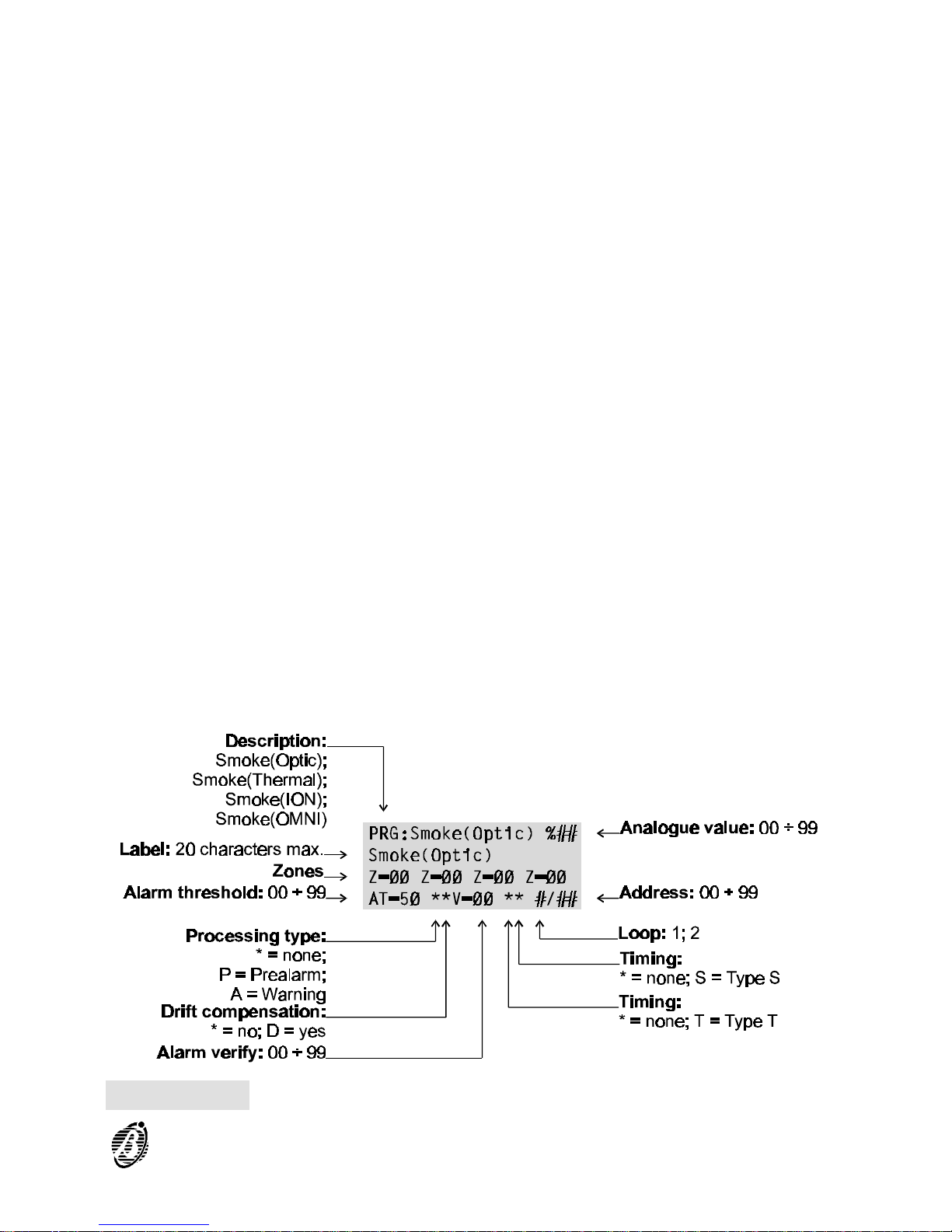
Figure 16 Fire detector parameters
PROGRAMMING 45
Page 46
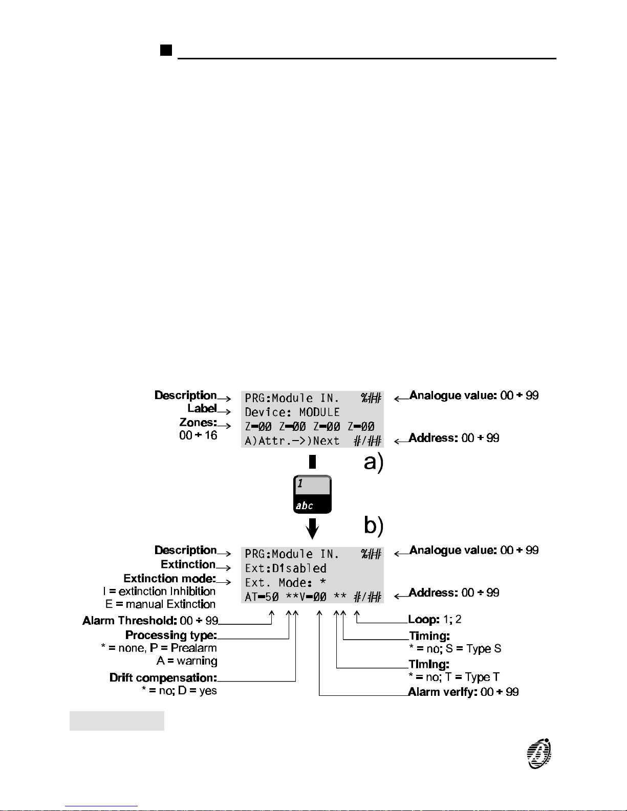
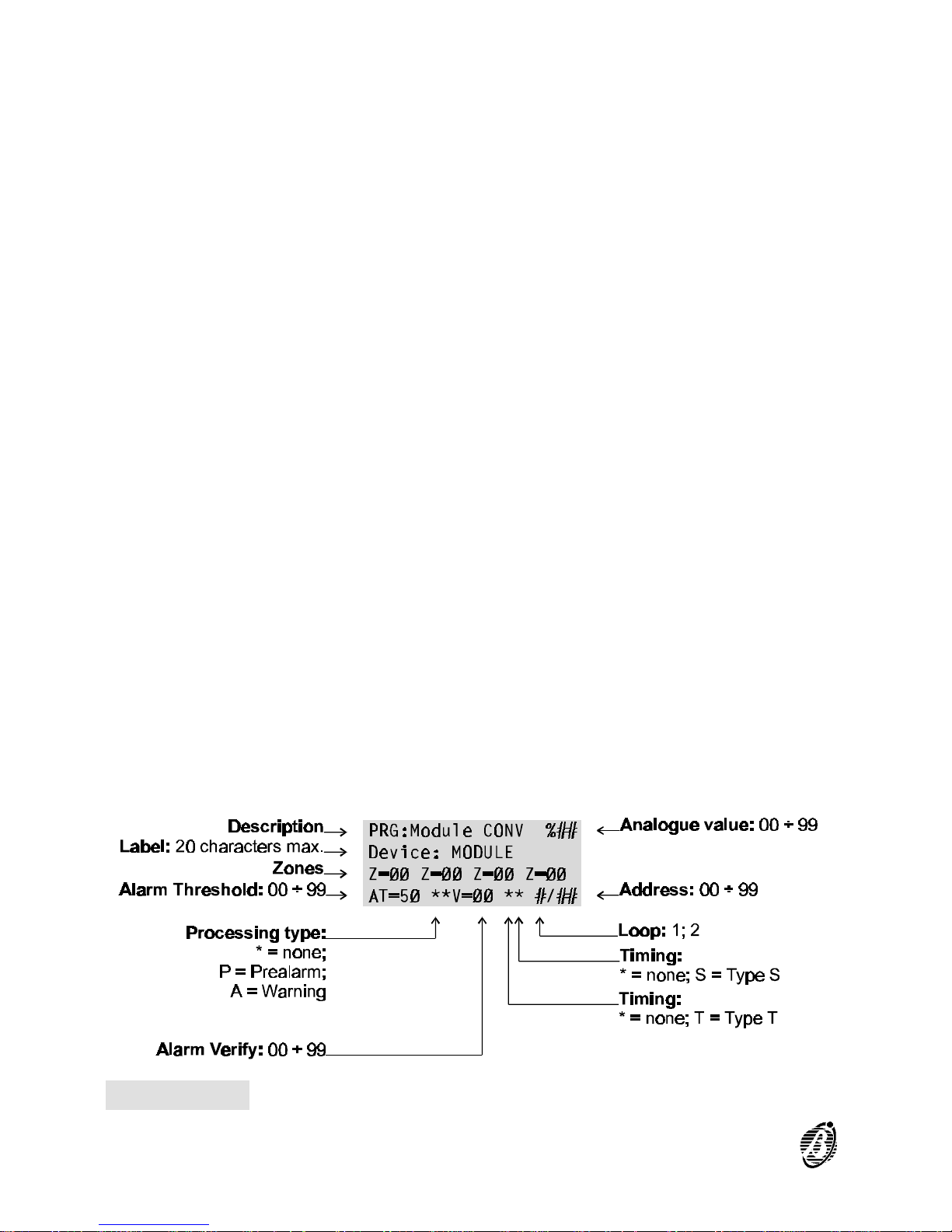
Programming: Input modules
Figure 17 shows the input module parameters.
Ø To access the parameters shown in figure 17b ---- position the cursor on
the third line of the display then press key 1.
Ø Most of the input module parameters are described in the "Programming:
Fire Detectors" section. The following parameters are for input modules
only.
Extinction If this option is enabled, the device will operate in accordance with the se-
lected Extinction Mode (see below).
Extinction mode This option determines whether the input module must activate the devices
and outputs programmed as Manual Extinction (E) or Inhibit Extinction (I).
Figure 17 Input module parameters
46 Analogue Fire Control Panel FireClass200
Page 47
Programming: Output modules
Figure 18 shows the output module parameters.
Ø To access the parameters shown in figure 18b ---- position the cursor on
the third line of the display then press key 1.
Ø Most of the output module parameters are described under "Programming:
Fire Detector". The following parameters are for output modules only.
Associated
Zones
Each output module can be associated with up to 4 of the 16 software
zones. The output module will activate when any one of its zones goes into
ALARM status.
PRG:Module OUT. %##
P=ØSØØ P=ØSØØ P=ØSØØ
Extinction : **
G:***,***,**** **
PRG:Module OUT. %##
Device: MODULE
Z=ØØ Z=ØØ Z=ØØ Z=ØØ
A)Attr.—>)Next #/##
a)
b)
Extinction type:
**; E1; E2; E3; E4
Fault:
*** = none;
Ft = Fault;
FtN = Net Fault
Description
Desciption
Label: 20 characters max.
Zones:
00 ÷ 16
Analogue value:
00 ÷ 99
Analogue value: 00 ÷ 99
General conditions
Alarm:
*** = none;
AI = Alarm;
2AI = Double Knock
Prealarm:
**** = none;
;
WrnN = Net Warning;
;
Pre =Prealarm
PreZ=Prealarm Zone
Wrn =
WrnZ = Zone Warning
WrnP = Point Warning;
Warning
Points
Loop: *; 1; 2
Type:
S = Sensor;
M = Module
Address: 00 ÷ 99
Bypass supervisory output :
** = Check output fault;
IF = (Ignore fault);
Don’t check output fault
Figure 18 Output module parameters
PROGRAMMING 47
Page 48
Associated
Points
Each output module can be associated with 3 Input Points. If any one of its Input Points goes into ALARM status, the output module will activate.
For each Point it is necessary to indicate:
Ø the loop the device is connected to (1 or 2);
Ø the device type - Detector (D) or a module (M);
Ø the device address (01 through 99 or CL = Conventional Line).
Extinction mode This parameter establishes the operating modes and times applied by the
output module during extinction operations.
To program the Extinction mode, select the Extinction Mode option from
the OPTIONS menu.
If ** is programmed (at default) the output module will not be used in extinction operations.
General
conditions
This option will allow you to select the conditions that will activate the output module:
Ø ALARM (Al) or Network ALARM (NAl);
Ø Fault (Ft) or Network Fault (NFt);
Ø Prealarm (Pre), Prealarm Zone (PreZ), Warning (Wrn) or Network Warning
(NetW), ZWrn (Zone Warning) or PWrn (Point Warning).
If the "ZWrn" option is enabled, the control panel will activate the output
when one of its associated zones goes into prealarm status. If the "PWrn"
option is enabled, the control panel will activate the output when one of its
associated points goes into Warning status.
Bypass
supervisory
output
If this option is enabled, the control panel will not signal output faults.
Therefore, the control panel will be able to manage M201E-240 output
modules (output modules with 230Vac switching relays), and M201E output modules with the Bypass supervisory output attribute. Figure 18
shows the respective programming template. The Bypass supervisory
Figure 19 Conventional-Zone module parameters
48 Analogue Fire Control Panel FireClass200
Page 49
output and Double Knock options can be programmed on the Output
Modules page of the FireSoftware application.
Double Knock
(on Zone or
System)
If this option is enabled, and the output is associated with zones, the
control panel will not activate the output until two detectors on the same
zone signal alarm status (Double Knock on zone).
Each zone has a Verify double-knock timer ---- if the timer setting is
higher than 0, the control panel will consider Double Knock on Zone
events to be valid ONLY when two devices signal alarm status within the
preset time.
If this option is enabled, and the output is NOT associated with zones,
the control panel will activate the output when any two of the system detectors signal alarm status (Double Knock on system).
If the output has been programmed to operate in AND mode, the control
panel will consider Double Knock events as single events and will not activate the output until a second alarm event occurs (e.g. Callpoint alarm).
NOTE: Double Knock on system events are not associated with timers.
Programming: Conventional Zone module
Figure 19 shows the Conventional Zone module parameters. These parameters are as per Fire detectors.
Programming: Repeaters and Slave panels
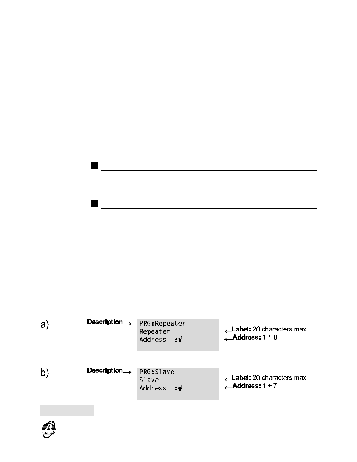
Figure 20a shows the repeater panel parameters. Figure 20b shows the
slave panel parameters. The following parameters are valid for both.
Description This is the non-editable description of the device type.
Label This is the editable device label (up to 20 characters can be entered). The
label is the device identifier.
Address This shows the device address.
Figure 20 (a) Repeater and (b) Slave Panel parameters
PROGRAMMING 49
Page 50
Devices
The Device option from the PROGRAMMING menu will allow you to
change the parameters of the Devices enrolled on loops 1 and 2.
The Device option also applies to the parameters of the Conventional line
(terminal [LC]), and those of the Bell Outputs on the Main board (terminals
[Cx]) and on Expander Outputs (terminals [Cx]).
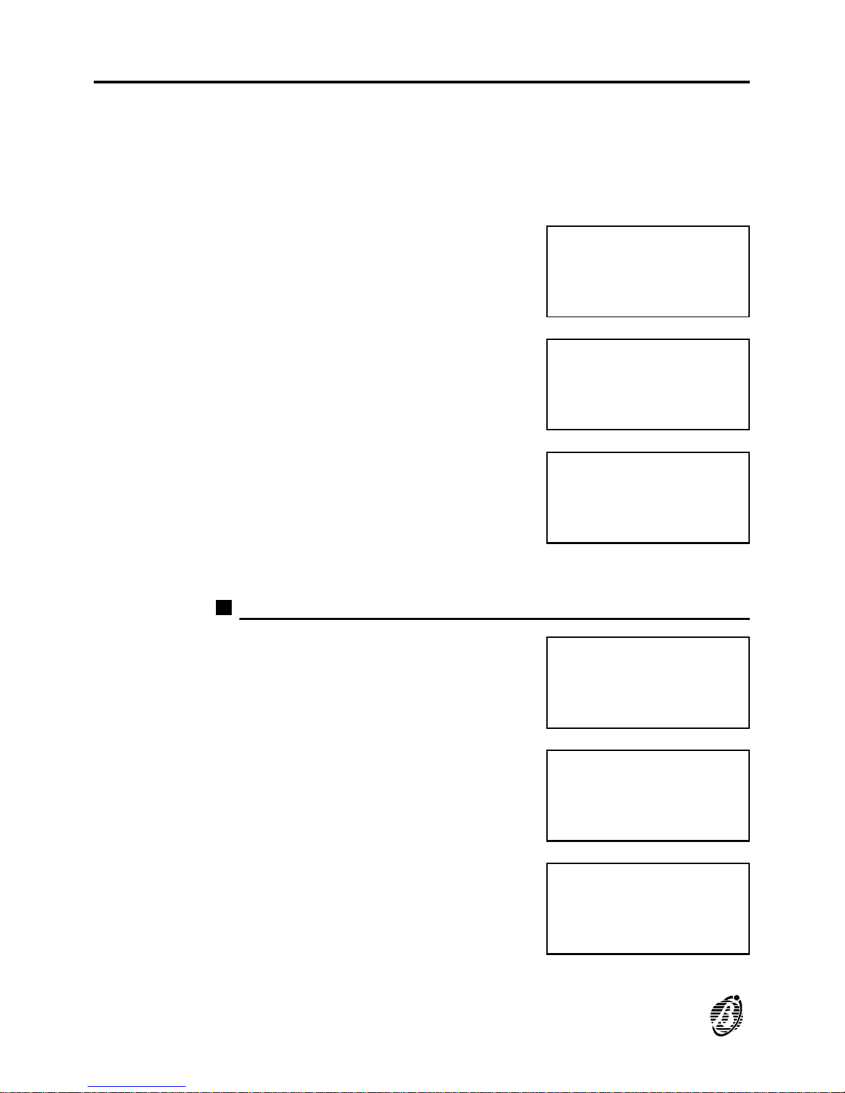
Select the Device option from the PRO-
GRAMMING menu (press 2).
If the control panel concerned is a SLAVE
the display will show ...
If the control panel concerned is the
MASTER panel the display will show ...
Select the required option and refer to the respective section.
Loop 1 and Loop 2
1. Select LOOP 1 or LOOP 2 from the DEVICE menu.
2. Enter the device address (for parameter
changes). Press the ↑ key to change the
Conventional Line parameters (terminal
[LC]), and refer the instructions in the
"Conventional Line" section.
3. If the entered address is valid the display
will be as shown in the "Auto learning"
section. If not, the display will show the
Device not configured message. Press
ESC to exit and go back to step 2.
1=Auto 2=Devices
3=PassWD 4=MesINI
5=Zones 6=Opt 7=Sys
8=Ver 9=Def Ø=Tel
PRG: Devices
1=LOOP 1 2=LOOP 2
3=Outputs BELL
NET not supported
PRG: devices
1=LOOP 1 2=LOOP 2
3=Outputs BELL
4=NET
PRG: Devices
1=LOOP 1 2=LOOP 2
3=Outputs BELL
4=NET
PRG: devices L1
Enter Address
Sensors L1: 1/##
Modules L1: 1/__
DEVICES LOOP1
Device not
configured
on LOOP 1
50 Analogue Fire Control Panel FireClass200
Page 51
To view the parameters of other devices on the same loop ---- work through
the steps in the "Auto learning" section. Press ESC to exit and go back to
step 2.
Conventional Line
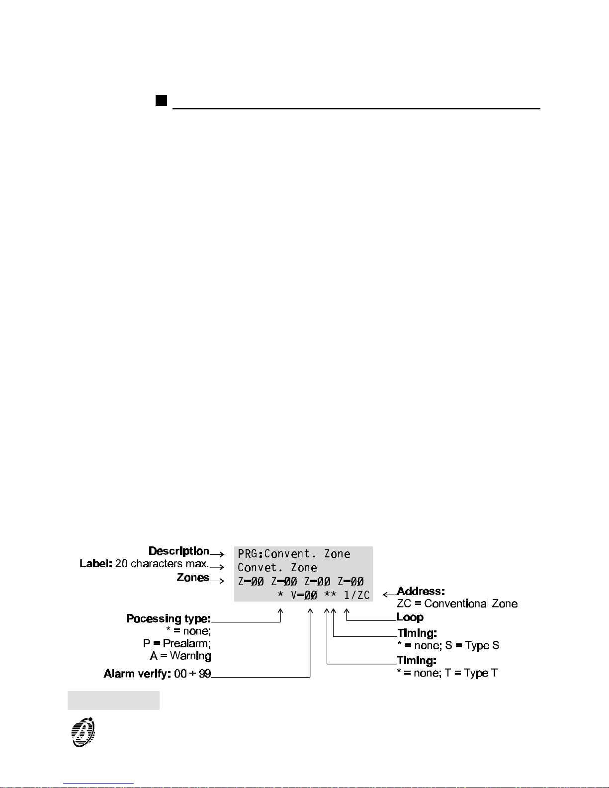
Figure 21 shows the parameters of the Conventional Line (terminal [LC]).
Conventional Line programming is as per analogue detectors. Refer to the
"Programming: Fire detectors" section for the description of the parameters
shown in figure 17.
+
The Alarm threshold value is not valid for the Conventional Line, as the
connected detectors supply discrete values only (alarm, open/short-circuit).
Figure 21 Conventional Line parameters
PROGRAMMING 51
Page 52
Bell Outputs
1. Select Bell Outputs option from the DEVICE menu to program the parameters of
the Main board bell outputs (terminals
[Cx]), and Output-expander bell outputs
(terminals [CX]).
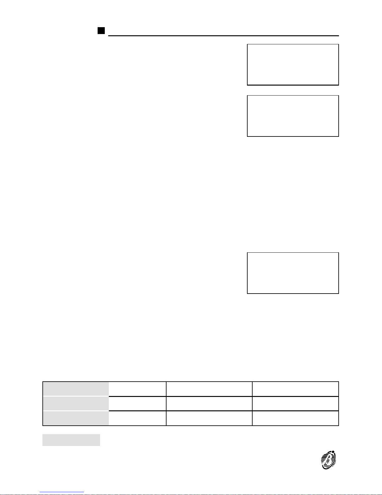
2. Enter the address of the bell output concerned. Table 1 shows the corresponding
Addresses of the bell output terminals on
the Main board and Output expanders.
The display will show the message in figure 22a. To access the parameters shown in figure 22b ---- position the cursor on the third line of the display and then press key 1.
Most of the bell output parameters are described in detail in the "Output
Module" section. The following parameters are for bell outputs only.
+
Address 01 corresponds to the Type C Output. The Type C Output is nonprogrammable, and will be activated each time the control panel goes into
ALARM status (it is possible to modify the label of the Type C Output).
ITemp When this option is selected the output will be activated in accordance with
the times set for option 1 from the OPTIONS menu.
If an invalid output or wrong address is en-
tered (accepted values are 01 through 16)
the display will show the Output not avail-
able message. Press ESC to go back to
step 2.
To view the parameters of the other bell outputs, follow the procedure described in the "Auto-learning" section. Press ESC to go back to step 2.
Double knock As per the same option for Output Modules (page 48).
Zone Warning As per the same option for Output Modules (page 48).
Point Warning As per the same option for Output Modules (page 48).
PRG: Devices
1=LOOP 1 2=LOOP 2
3=Outputs BELL
4=NET
PRG: Output Bells
Enter Address
Output BELL : ##
Outputs BELL
Output
not
available
POSITION Main board Output expander no. 1 Output expander no. 2
TERMINALS C C2 C3 C4 C5 C6 C7 C8 C9 C10 C11 C12 C13 C14C15 C16
ADDRESSES 01 02 03 04 05 06 07 08 09 10 11 12 13 14 15 16
Table 1 Terminal number and address
52 Analogue Fire Control Panel FireClass200
Page 53
Network
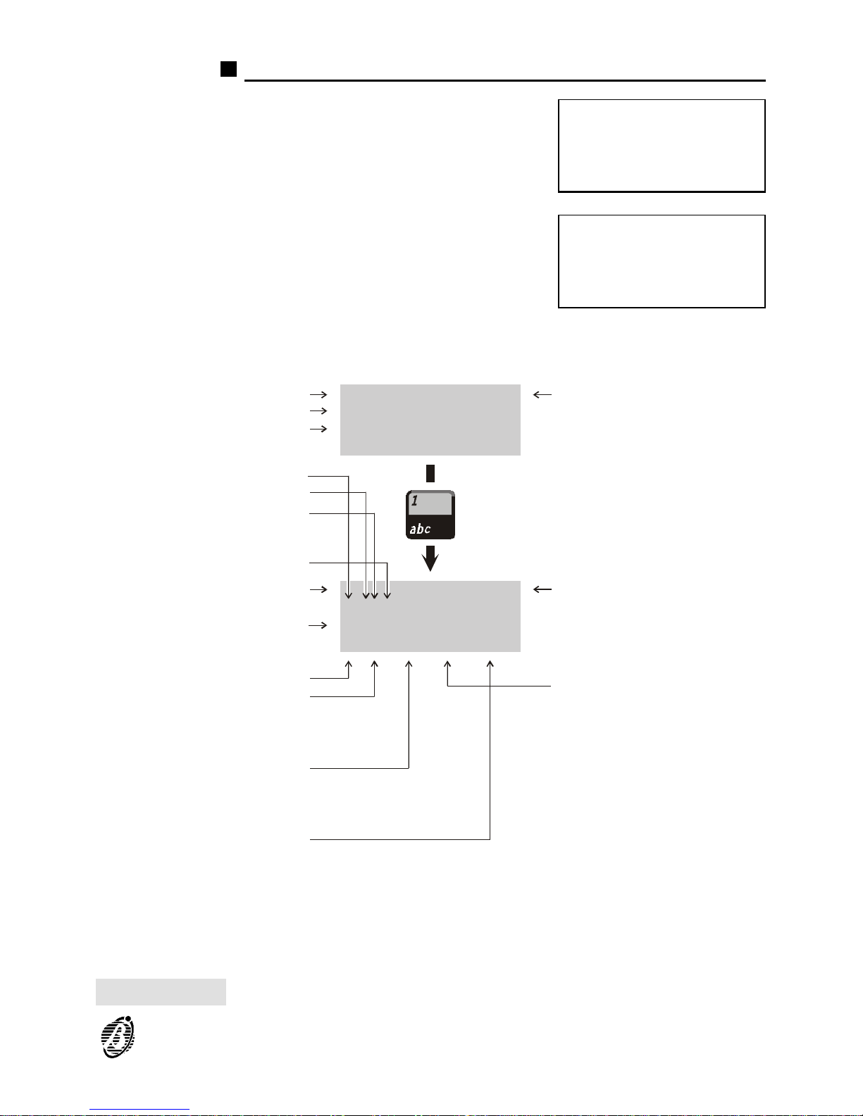
1. Select the NET option from the DEVICE
menu (press 4) for the RS485 Network device parameters. Press ESC to exit and
step back to the PROGRAMMING menu.
2. Enter the device address. Press ESC to
exit and step back.
PRG: Devices
1=LOOP 1 2=LOOP 2
3=Outputs BELL
4=NET
PRG: NET DEVICES
Enter Address
Repeater: ##
Slave: __
PRG: Output BELL :##
P=ØSØØ P=ØSØØ P=ØSØØ
Extinction : **
G:***,***,****,****
PRG:Output BELL :##
Output Bell
Z=ØØ Z=ØØ Z=ØØ Z=ØØ
A)Attr.—>)Next
a)
b)
Extinction type:
**; E1; E2; E3; E4
Fault:
*** = none;
Ft = Fault;
FtN = Net Fault
Description
Description
Label: 20 characters max.
Zones:
00 ÷ 16
Address:
01 ÷ 16
Address: 01 ÷ 16
General conditions
Alarm:
*** = none;
AI = Alarm;
2Al = Double Knock
Prealarm:
**** = none;
Wrn = Warning;
WrnN = Net Warning
Pre = Prealarm;
PreN = Net Prealarm;
WrnZ = Zone Warning;
WrnP = Point Warning;
PreZ = Prealarm zone
Points
Loop: *; 1; 2
Type:
S = Sensor;
M = Module
Address: 00 ÷ 99
Output timing:
**** = no;
ITemp = yes.
Figure 22 Bell Output parameters
PROGRAMMING 53
Page 54
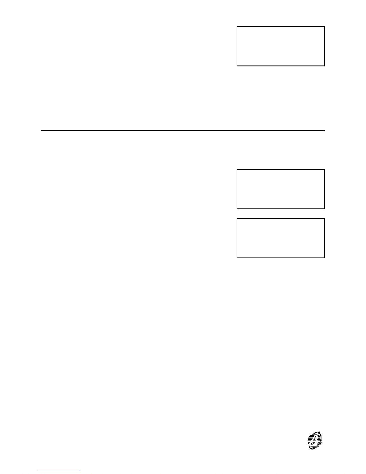
3. The display will show the respective parameters (refer to "Programming: Repeater and Slave panels" section). If not,
the display will show the Device not con-
figured message. Press ESC to step
back.
To view the parameters of the other devices on the RS485 Network, follow
the procedure described in the "Auto-learning" section. Press ESC to step
back to the previous menu.
Password (PassWD)
The PassWD option from the PROGRAMMING menu will allow you to
change the Installer and user codes. Codes with 1 to 5 digits (0 through 9).
Select the PassWD option from the PRO-
GRAMMING menu (press 3).
The display will show ...
Select option 1 or 2 and refer to the respective section.
DEVICES NET
Device not
configured
on NET
1=Auto 2=Devices
3=PassWD 4=MesINI
5=Zones 6=Opt 7=Sys
8=Ver 9=Def Ø=Tel
CODES
Programming
1=Installer Code
2=User Code
54 Analogue Fire Control Panel FireClass200
Page 55
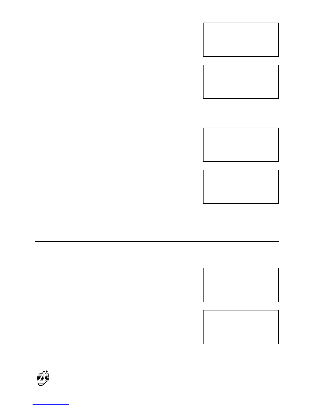
Installer code The installer code accesses all menus.
The default installer code is 00000.
Enter the new installer code: each digit will
be masked by the symbol Q.
Press the ↵ key to confirm the new code or press ESC to exit without saving.
User code The user code can access the MODIFY-
ING menu only. The default user code is
11111.
Enter the new user code: each digit will be
masked by the symbol Q.
Press ↵ to confirm the new code or press ESC to exit without saving.
Welcome Message (MesINI)
The 20-character Welcome Message (Fire Class 200 at default), shown
on the first line of the display during standby can be edited as follows.
Select the MesINI option from the PRO-
GRAMMING menu (press 4).
Enter the new message then press the ↵
key to confirm or ESC to exit without saving.
Programming:
INSTALLER CODE
enter the new
code : XXXXX
Programming:
INSTALLER CODE
enter the new
code : *XXXX
Programming:
USER CODE
enter the new
code : XXXXX
Programming:
USER CODE
enter the new
code : *XXXX
1=Auto 2=Devices
3=PassWD 4=MesINI
5=Zones 6=Opt 7=Sys
8=Ver 9=Def Ø=Tel
PROGRAMMING
WELCOME MESSAGE
enter the new one:
welcome message¤
PROGRAMMING 55
Page 56
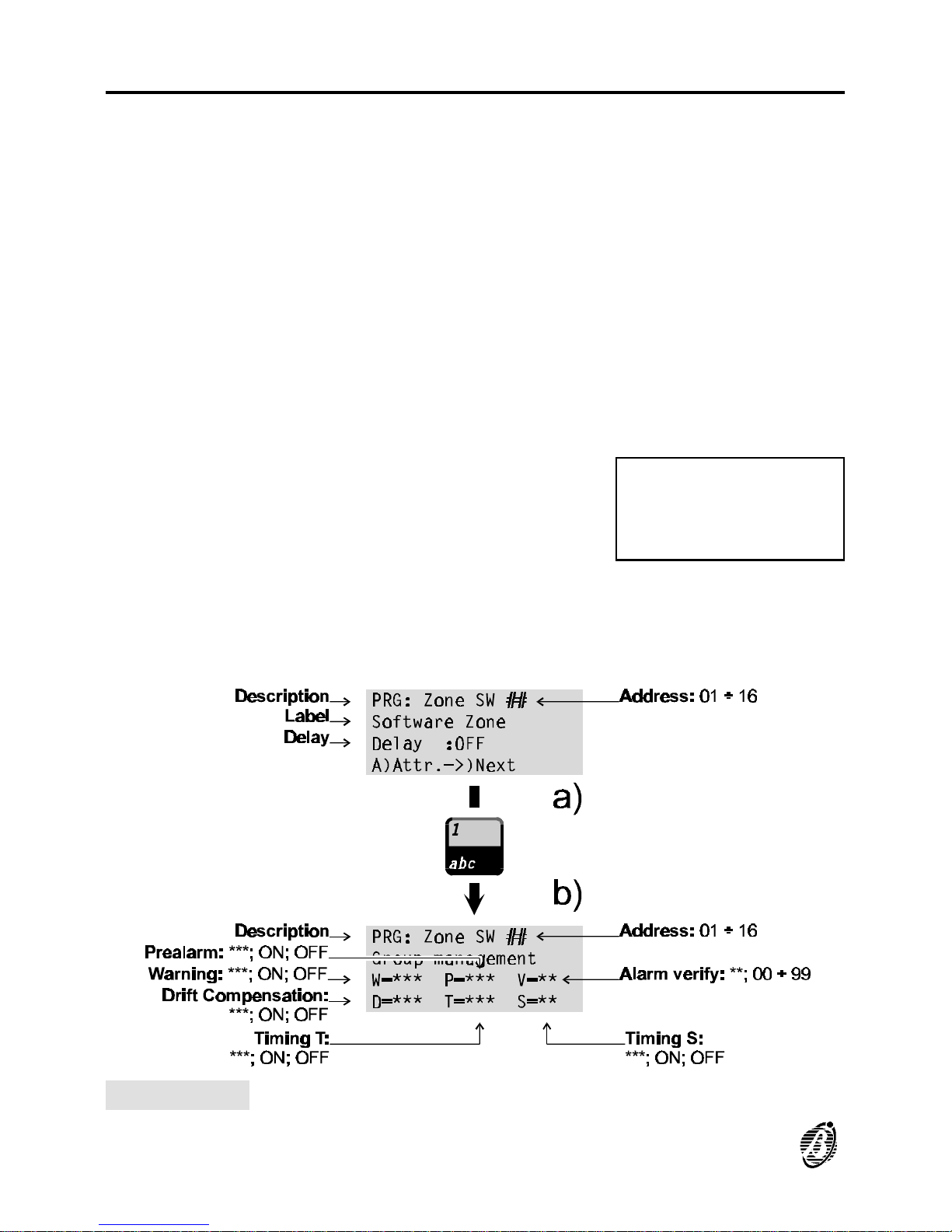
Zones
The Zone option from the PROGRAMMING menu will allow you to access
the software-zone parameters.
The same parameters can be programmed for all the devices associated
with software zones.
You can use the Zones option to associate output device groups with input
points.
The software zones parameters will be applied automatically to all the devices associated with the cone concerned.
If a device is associated with several software zones, the last software
zones to be programmed will determine the valid parameters.
Therefore, the last parameter will be the valid parameter.
Select the Zone option from the PRO-
GRAMMING menu (press 5) to access
and program the parameters of the software zones.
The display will be as per figure 23a. Position the cursor on the third line
and press 1 to access the parameters shown in figure 23b.
1=Auto 2=Devices
3=PassWD 4=MesINI
5=Zones 6=Opt 7=Sys
8=Ver 9=Def Ø=Tel
Figure 23 Software Zone parameters
56 Analogue Fire Control Panel FireClass200
Page 57
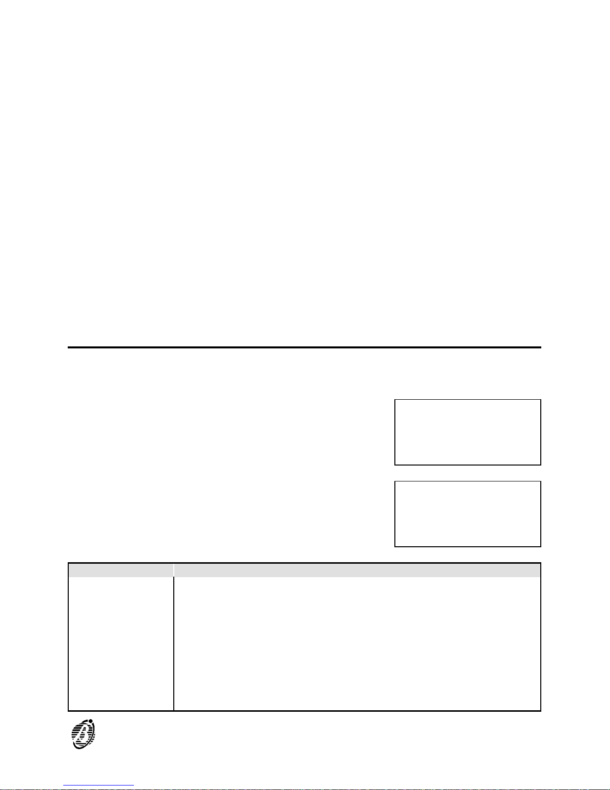
Most of the software zones parameters are described in the "Programming: Fire detectors" section. The following parameters are for software
zones only.
Delay Select ON to apply the Fixed Delay and PAS Delay to the software zones.
The Fixed Delay will start when an alarm condition occurs on a software
zones with the Delay enabled (ON). The Fixed Delay will be signalled by
blinking on the software zones LED.
Press ACK to extend the running Fixed Delay - the PAS Delay (if enabled) will be added automatically to the Fixed Delay.
The software zones will go into ALARM status when the total time of both
delays elapses.
+
The Fixed Delay and PAS Delay (Positive Alarm Sequence) can be en-
abled, and programmed by means of the D option from the OPTIONS
menu.
OPTION
Many of the parameters can be programmed through the Opt option from
the PROGRAMMING menu.
Select the Opt option from the PRO-
GRAMMING menu.
Select the required option, in accordance
with the following table, and refer to the respective section. Press ESC to step back
to the PROGRAMMING menu.
KEYS OPTIONS
0 Prealarm time
1 Warning threshold
2 Verify
3 Drift Compensation (VALUE CONTROLLED AUTOMATICALLY)
4 Timer
5 Special Timer
6 Holidays
7 Delays (Fixed and PAS)
8 Pulse
9 Extinction modes
1=Auto 2=Devices
3=PassWD 4=MesINI
5=Zones 6=Opt 7=Sys
8=Ver 9=Def Ø=Tel
PRG: OPTION
Ø=P 1=W 2=V 3=D 4=T
5=S 6=H 7=D 8=Pulse
9=Extinction mode
PROGRAMMING 57
Page 58
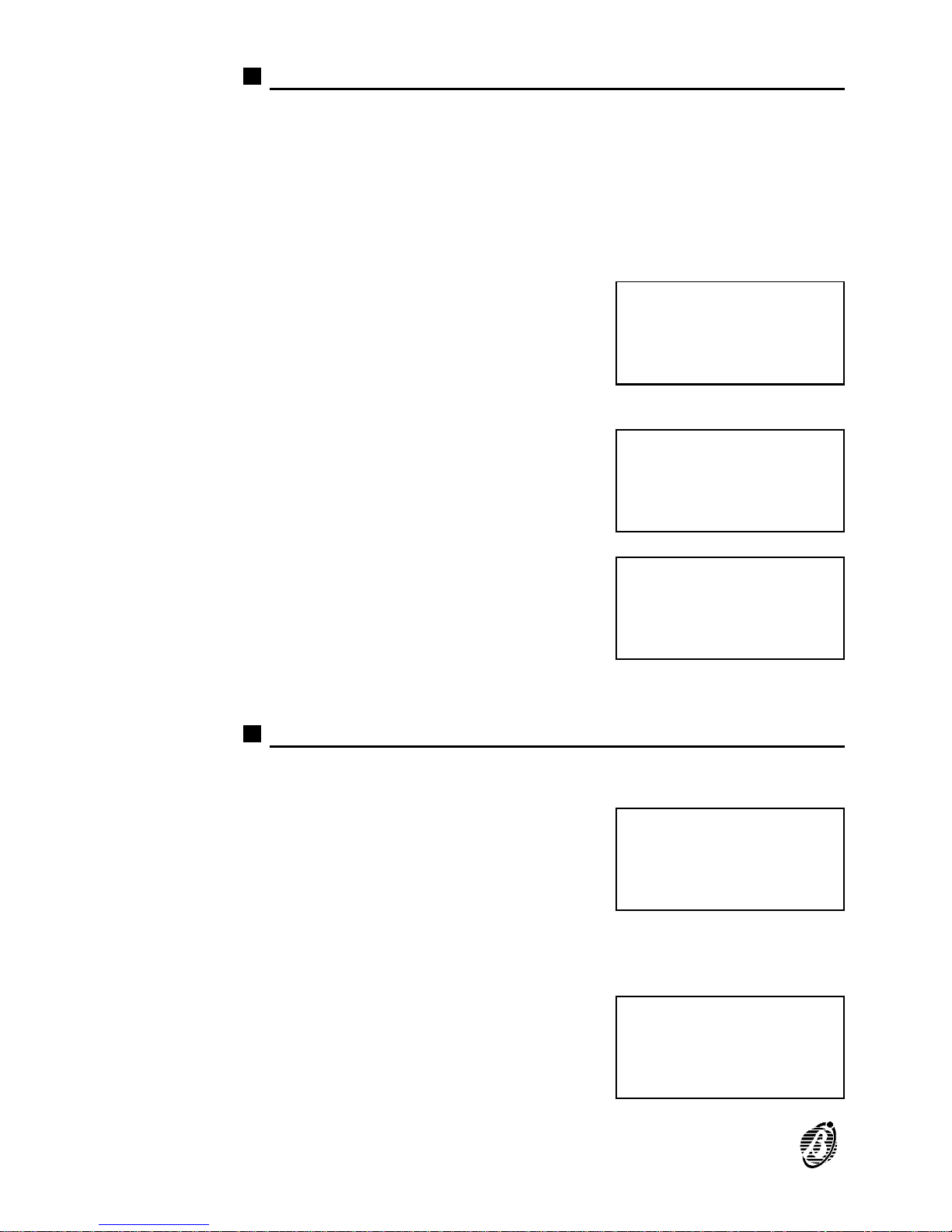
Prealarm time (P)
An input device programmed with Prealarm time will generate ALARM
status when the prealarm time elapses. Prealarm status is signalled by:
Ø an audible signal emitted by the control panel and repeater panels;
Ø blinking on the PREALARM LED;
Ø blinking on the LEDs of the associated software zones;
Ø the following message on the display (from Firmware version 4.0)
Select P from the OPTION menu (press 0)
to program the Prealarm time.
Enter values of 0.00 through 20.00 minutes with steps of 0.5 minutes. The default
prealarm time is 1 minute.
Press the ↵ key to confirm or ESC to exit without saving.
Warning Threshold (W)
If a loop device exceeds the preset Warning Threshold, the Control panel
will generate Warning status.
The Warning Threshold is valid for loop devices with the Warning attribute.
Select W from the OPTION menu
(press 1).
PREALARM 01/=002
FIRE CLASS 00
Device: SEN1/01
Software Zone 01
PRG: OPTION
Ø=P 1=W 2=V 3=D 4=T
5=S 6=H 7=D 8=Pulse
9=Extinction mode
PRG: OPTION
PREALARM
Enter Prealarm
time : Ø1,Ømin.
Control
Panel in
WARNING
Status !
PRG: OPTION
Ø=P 1=W 2=V 3=D 4=T
5=S 6=H 7=D 8=Pulse
9=Extinction mode
58 Analogue Fire Control Panel FireClass200
Page 59
The warning thresholds of each loop device can be programmed individually, as follows:
Enter a value of 00 through 99% with
steps of 1%. The Warning Threshold default value is 30%.
Press the ↵ key to confirm, or ESC to exit without saving.
Alarm Verify (V)
Select the Alarm Verify option for the Verify Time. The Verify Time will
start when a device exceeds the ALARM Threshold.
If the Analogue Value is higher than the Alarm threshold when the Verify
Time expires, the control panel will generate ALARM status. However, if
the Analogue Value drops below the Alarm threshold before the end of the
Verify Time, the control panel will hold Standby status, and will increase
automatically the value of the Verify Counter of the device.
If the Analogue Value is higher than the Alarm threshold, when the Verify
Counter reaches the programmed value, the control panel will generate an
ALARM. To delete (clear) all the Verify Counters ---- select the Delete
Verify option from the MODIFYING menu.
+
If another device exceeds the ALARM threshold during the Verify Time,
the control panel will generate an instant ALARM.
Select V from the OPTION menu (press 2)
to program the Verify Time.
Select the Alarm Verify option (00.0 minutes at default). Enter the required value.
Accepted values: 00.0 through 20.0 minutes in steps of 00.5 minutes.
Press ↵ to confirm or ESC to exit without saving.
PRG:Warning thresh.
Loop: 1 M Addr. 01
Device Label
Warn: threshold:%3Ø
PRG: OPTION
Ø=P 1=W 2=V 3=D 4=T
5=S 6=H 7=D 8=Pulse
9=Extinction mode
PRG: OPTION
Alarm Verify
Verify Time: ØØ.Ømin
PROGRAMMING 59
Page 60

Drift Compensation
Automatic Drift Compensation on detectors.
60 Analogue Fire Control Panel FireClass200
Page 61
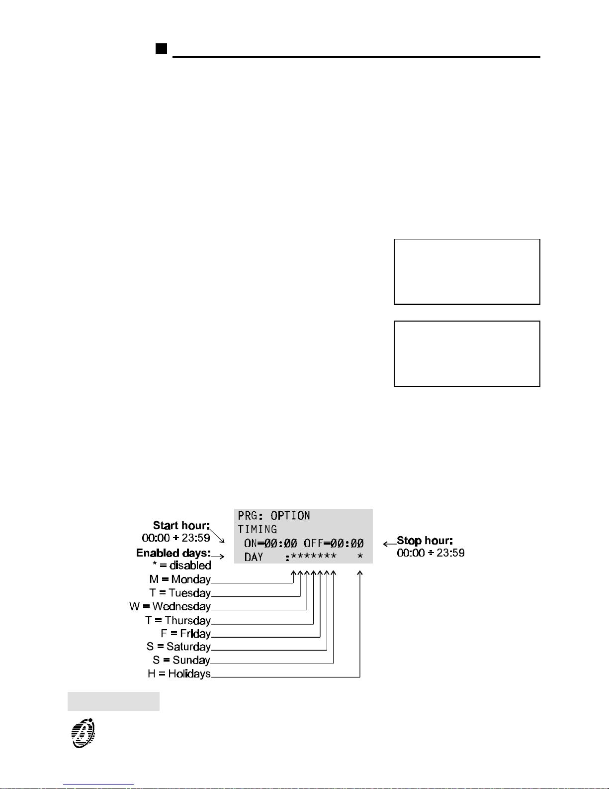
Timer and Special Timer (T and S)
In order to lower the false alarm rate, the Alarm Threshold of analogue detectors must be INCREASED during Day mode (to allow for cigarette
smoke, heaters, etc.).
The Timer can be set to activate/deactivate (ON/OFF) the Increased
Alarm Threshold value.
The Special Timer is especially useful in work places with split shifts (factories, offices, etc.).
Both Timers have exactly the same programming and operating modes.
+
Ensure that the control-panel calendar and clock are properly set.
Select T from the OPTION menu (press 4)
to access the Timer parameters.
Fig. 24 shows the respective parameters.
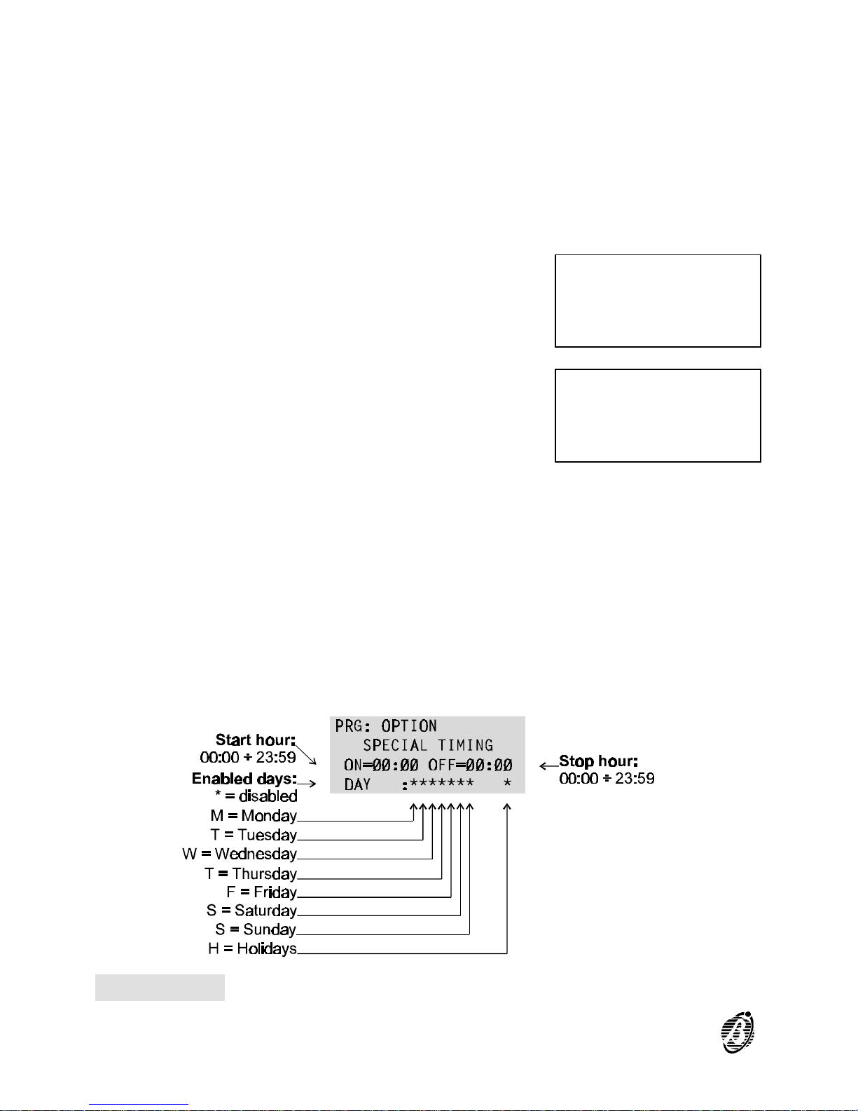
Select S from the OPTION menu (press 5)
to access the Special Timer parameters.
Fig. 25 shows the respective parameters.
ON Enter the time of the day (hour and minutes) when the Alarm Threshold
must be increased by the non-modifiable Default value.
OFF Enter the time of the day (hour and minutes) when the programmed Alarm
Threshold must be restored.
Days Enter the days of the week when the ON-OFF times must be applied.
PRG: OPTION
Ø=P 1=W 2=V 3=D 4=T
5=S 6=H 7=D 8=Pulse
9=Extinction mode
PRG: OPTION
Ø=P 1=W 2=V 3=D 4=T
5=S 6=H 7=D 8=Pulse
9=Extinction mode
Figure 24 Timer parameters
PROGRAMMING 61
Page 62
+
The Timer will control detectors on the loop with the T attribute.
+
The Special Timer will control detectors on the loop with the S attribute.
H option The H option offers further flexibility to the Timers as it will allow you to in-
crease the Alarm Threshold on days which would normally be exempt (e.g.
Sunday). A maximum of 5 dates can be programmed for this option.
The dates selected for the Timer option can be applied to the Special
Timer and vice versa.
Select H from the OPTION menu
(press 6).
Enter the date. Cancel the day and/or
month number by entering 00.
Press ↵ to confirm or ESC to exit without saving.
PRG: OPTION
Ø=P 1=W 2=V 3=D 4=T
5=S 6=H 7=D 8=Pulse
9=Extinction mode
PRG: OPTION
HOLIDAYS
DAY : ØØ/ØØ ØØ/ØØ
ØØ/ØØ ØØ/ØØ ØØ/ØØ
Figure 25 Special Timer parameters
62 Analogue Fire Control Panel FireClass200
Page 63
Delay
Use the Delay option to access and program the Fixed Delay and PAS
Delay.
Fixed Delay The Fixed Delay will start when alarm conditions occur on software zones
with the Delay attribute (ON). The Fixed Delay will be signalled by blinking
on the Software Zones LED.
Press ACK to extend the running Fixed Delay. The PAS Delay (if enabled) will be added to the Fixed Delay.
The software zones will generate ALARM status when the total time of
both delays expires.
The Fixed Delay and PAS Delay (Positive Alarm Sequence) must be en-
abled (ON) and programmed using the D option from the OPTIONS menu.
+
If another software zone detects ALARM conditions during the delay, the
control panel will override the delay and generate an instant ALARM.
Select D from the OPTION menu (press 7)
to access the Fixed and PAS delays.
Enter the Fixed Delay and the PAS Delay
times (accepted values 0 through 20 minutes in steps of 0.5 minutes).
Select ON to enable the PAS Delay.
The default value is the same for both Delays: 2 minutes; OFF.
Press the ↵ key to confirm, or ESC to exit without saving and step back to
the previous menu.
PRG: OPTION
Ø=P 1=W 2=V 3=D 4=T
5=S 6=H 7=D 8=Pulse
9=Extinction mode
PRG: OPTION
DELAY
Fixed:ØØ,Ø PAS:****
PAS=OFF
PROGRAMMING 63
Page 64
Pulse
The Pulse option is for the ON and OFF Times of the Bell Outputs.
Select Pulse from the OPTION menu
(press 8).
Enter the required ON and OFF Times
The default value is 0 (accepted values: 0
through 25.5 seconds in steps of 0.5 seconds).
+
The ON and OFF Times will be valid for the Bell Outputs programmed as
General Condition (refer to "Bell Output").
Extinction Mode
The Extinction Mode option will allow you to set up to 4 Extinction Modes.
The Extinction Mode parameters determine the operating mode of the out-
put devices and bell outputs, as follows.
Delay This parameter determines the output device delay. The default value is 30
seconds (accepted values:30 through 99 seconds in steps of 1 second).
Operating Mode This parameter determines how the Extinction Inhibition feature will work.
Ø ADD (default) - Extinction Inhibition will add 90 seconds to the pro-
grammed Delay;
Ø STOP - Extinction Inhibition will stop the Delay 10 seconds before it is due
to end. If Extinction Inhibition is undone, the Delay will restart and run for
10 seconds;
Ø FULL - Extinction Inhibition will refresh the Delay to its initial value. If Ex-
tinction Inhibition is undone, the Delay will restart.
+
If an activating condition occurs during Extinction Inhibition, Extinction devices will be activated immediately.
LOG The LOG (logic) parameter establishes the conditions that will activate ex-
tinction.
Ø OR (default) - only one activating condition need occur.
Ø OFF - at least two activating conditions must occur simultaneously.
Time ON (TMP) This determines the time that Extinction devices will be active. Enter val-
ues from 0 through 20 minutes - 0 (zero) means that the Extinction devices
PRG: OPTION
Ø=P 1=W 2=V 3=D 4=T
5=S 6=H 7=D 8=Pulse
9=Extinction mode
PRG: OPTION
PULSES (IPul)
Time ON =ØØ,Ø sec
Time OFF =ØØ,Ø sec
64 Analogue Fire Control Panel FireClass200
Page 65
will stop when the control panel is RESET. The default Time ON is 0
(TMP indefinite).
The programmed Delay will start when the activating conditions specified
in the LOG (logic) parameter occur.
It is possible to stop Extinction devices whilst the Delay is running; as
specified in the Mode parameter.
When the programmed Delay elapses the Extinction devices will be activated for the programmed Time ON.
The enabled output modules and the Bell Outputs will be activated after
the programmed Delay.
They will hold the activated status for the programmed Time ON .
+
The Extinction Mode settings will be valid for the Outputs with the same
Mode type (refer to "Extinction mode" of the Output modules and Bell Outputs).
1. Select the Extinction Mode option from
the OPTION menu (press 9) to access and
program the Extinction Modes.
2. Select the required Extinction Mode, or
press ESC to step back to the OPTION
menu.
3. DLY is for the Delay; TMP stands for Time
ON.
4.
Press the ↵ key to confirm and go back to step 2. Press ESC to exit without saving and go back to step 2.
PRG: OPTION
Ø=P 1=W 2=V 3=D 4=T
5=S 6=H 7=D 8=Pulse
9=Extinction mode
PRG: OPTION
Choose Extinction:
1= Ext1 2= Ext2
3= Ext3 4= Ext4
PRG: OPTION
Extinction M.: E#
DLY=3Ø MODE=ADD TMP
LOG=OR TMP=ØØ,Ø min
PROGRAMMING 65
Page 66
System
Select the Sys option from the PROGRAMMING menu (press 7) to access
and program the system parameters.
The display will show ...
Select the required option, according to the following table, and refer to the
respective section or press ESC to step back to the PROGRAMMING
menu.
KEYS SYSTEM PARAMETERS
1 Date/Time
2 Blink
3 Wire
4 SIL (Silence)
5 WT (Walk Test)
6 NET (Network)
7 Printer
Date and Time
The Date/Time option from the SYSTEM menu is for the control panel
clock settings.
Select Date/Time option from the SYS-
TEM menu (press 1).
Enter the required Time and Date. Press
the ↵ key to confirm, or ESC to exit without
saving and step back to the SYSTEM
menu.
+
The day of the week must correspond to the selected date in order to ensure proper functioning.
1=Auto 2=Devices
3=PassWD 4=MesINI
5=Zones 6=Opt 7=Sys
8=Ver 9=Def Ø=Tel
PRG: SYSTEM
1=Date/Time 2=Blink
3=Wire 4=SIL 5=WT
6=NET 7=Printer
PRG: SYSTEM
1=Date/Time 2=Blink
3=Wire 4=SIL 5=WT
6=NET 7=Printer
PRG: SYSTEM
Date/Time
Time: ØØ:ØØ
Date: 24/11/98 Tue
66 Analogue Fire Control Panel FireClass200
Page 67
Blink
The analogue fire detectors are equipped with a LED which will blink when
the control panel reads the detector status.
Select the Blink option from the SYSTEM
menu (press 2) to enable/disable the detector LED.
Select the loop (L1 or L2) that the LEDs
are connected to. Select ON to enable and
OFF to disable the LED.
Select the address of the detector whose
LED must be enabled/disabled or ...
select the address range (from ... to) of the
detectors whose LEDs must be enabled/disabled.
Press the ↵ key to confirm or ESC to exit without saving and step back to
the SYSTEM menu.
Wires
Use the Wire option to specify the configuration of the control panel loops.
Select the Wire option from the SYSTEM
menu (press 3).
Select the configuration of each loop (2 or
4 wires). Press the ↵ key to confirm, or
ESC to exit without saving and step back
to the SYSTEM menu.
PRG: SYSTEM
1=Date/Time 2=Blink
3=Wire 4=SIL 5=WT
6=NET 7=Printer
PRG: SYSTEM
Blinking : L1 S ON
Device : 1/__
From: 1/__ to1/__
PRG: SYSTEM
Blinking : L1 S ON
Device : 1/##
From: 1/__ to1/__
PRG: SYSTEM
Blinking : L1 S ON
Device : 1/__
From: 1/## to1/##
PRG: SYSTEM
1=Date/Time 2=Blink
3=Wire 4=SIL 5=WT
6=NET 7=Printer
PRG: SYSTEM
Wires
Loop 1: 2 wires
Loop 2: 2 wires
PROGRAMMING 67
Page 68
Silence mode
The control panel SILENCE button will disable all Outputs in ALARM
status (Bell Outputs and Output modules), with the exception of the NONControlled Outputs (terminals [CM1-NC1-NO1] and [CM2-NC2-NO2]).
Select the SIL option from the SYSTEM
menu (press 4) to access and program the
Silence mode.
The display will show ...
Mode Select the Silence mode:
Ø Day (Default) - Silence status will be held until the SILENCE button is
pressed. The control panel will set to Day mode on power up.
Ø Night - Silence status will be held for the programmed Time ON, or until
the SILENCE button is pressed again.
Ø AUTO - Silence status will operate in Day Mode during the hours and days
programmed on the Timers (see Timer below), otherwise, it will operate in
Night Mode.
+
If an alarm condition is detected during Silence mode, the programmed
Outputs will be activated.
Time ON Enter the maximum Silence Time for Night Mode. Enter from 00.5 through
20.0 minutes with steps of 0.5 minutes. The default is 0.5 minutes (30 seconds).
Timer Select the Timer for AUTO mode. Select T
or S, or T and S as required. Both Timers
are programmed by means of the Timer
option from the OPTION menu.
Press the ↵ key to confirm, or ESC to exit without saving and step back to
the SYSTEM menu.
PRG: SYSTEM
1=Date/Time 2=Blink
3=Wire 4=SIL 5=WT
6=NET 7=Printer
PRG: SYSTEM
Silencing
MODE: Night
Time ON= ØØ,5 T S
PRG: SYSTEM
Silencing
MODE: Night
Time ON= ØØ,5 T S
68 Analogue Fire Control Panel FireClass200
Page 69
Walk Test
The Walk Test allows the installer to check proper functioning of the Input
Points of each separate software zones. When a software zones ---- in
Walk Test status goes into ALARM status, the control panel will activate
the Alarm Outputs for a period of 1 to 15 seconds (depending on the number of detectors on the loops).
+
The Extinction Outputs will not be activated.
1. Select the WT option from the SYSTEM
menu (press 5).
2. Select ON to enable the Walk Test.
3. Select the required Zone.
4.
Press the ↵ key to activate the Walk Test.
The Walk Test status will be signalled by:
Ø the message - WALK TEST ACTIVE ON ZONE: # (the Zone will be indi-
cated in the space filled by # in the example);
Ø Blinking on the TEST LED (0.5 second intervals);
Ø a long beep, followed by a long pause (2 second intervals).
Select OFF at step B to disable the Walk Test.
+
Test status will be abandoned automatically if any Zone, other than the
Zone in TEST status, goes into ALARM status.
+
Test status will be abandoned automatically if any type of Fault is detected.
PRG: SYSTEM
1=Date/Time 2=Blink
3=Wire 4=SIL 5=WT
6=NET 7=Printer
PRG: SYSTEM
Walk Test
Walk Test: ON
on Zone : Ø1
PRG: SYSTEM
Walk Test
Walk Test: ON
on Zone : ##
FIRE CLASS 2ØØ
WALK
TEST
ACTIVE ON ZONE: ##
PROGRAMMING 69
Page 70
Network
When the Fire control system is fully installed, and several control panels
are connected via RS485: one of the control panels must be programmed
as MASTER and all the others as SLAVES.
Select the NET option from the SYSTEM menu to program the MASTER
and SLAVES. It is possible to connect the MASTER panel to one of the
SLAVE panels on the network. In which case, the LEDs and display of the
MASTER panel will show the status and parameters of the SLAVE panel.
The commands made on the MASTER panel will be effective also on the
SLAVE panel.
Select the NET option from the SYSTEM
menu (press 6).
Status Select the operating mode of the control
panel: MASTER or SLAVE # (the address
1 through 7 will be indicated in the space
filled by # in the example). The example
shows the control panel programmed as
SLAVE 1 (default).
+
The control panel will RESET automatically each time the control panel
status is changed.
Remote
connection
Specify the remote connection of the
MASTER to a SLAVE panel.
Press the ↵ key to confirm, or ESC to exit without saving and step back to
the SYSTEM menu.
+
If Remote Connection with a SLAVE panel has been programmed, on exiting the NETWORK window, the MASTER panel display will be the same
as the slave.
Press the ACK key to end the remote connection. If no key is pressed
within 20 seconds the remote connection will end automatically. The MASTER panel will RESET when the connection ends.
PRG: SYSTEM
1=Date/Time 2=Blink
3=Wire 4=SIL 5=WT
6=NET 7=Printer
PRG: SYSTEM
NET
Cond.: Slave 1
****** -> ******
PRG: SYSTEM
NET
Cond.: MASTER
MASTER -> Slave #
70 Analogue Fire Control Panel FireClass200
Page 71
Printer
A serial printer can be connected to the RS232 port of the control panel,
for real-time printout of events.
Select Printer from the SYSTEM menu
(press 7).
Select ON to enable or OFF to disable the
Printer.
Press the ↵ key to confirm, or ESC to exit without saving and step back to
the SYSTEM menu.
Verify
The Verify option from the PROGRAMMING menu is reserved for future
use.
If the Ver option is selected from the PRO-
GRAMMING menu (key 8).
The display will show ...
Press ESC to step back to the PROGRAMMING menu.
PRG: SYSTEM
1=Date/Time 2=Blink
3=Wire 4=SIL 5=WT
6=NET 7=Printer
PRG: SYSTEM
Condition
Printer
ENABLED :OFF
1=Auto 2=Devices
3=PassWD 4=MesINI
5=Zones 6=Opt 7=Sys
8=Ver 9=Def Ø=Tel
PRG: VERIFY
Future Use
Future Use
Future Use
PROGRAMMING 71
Page 72
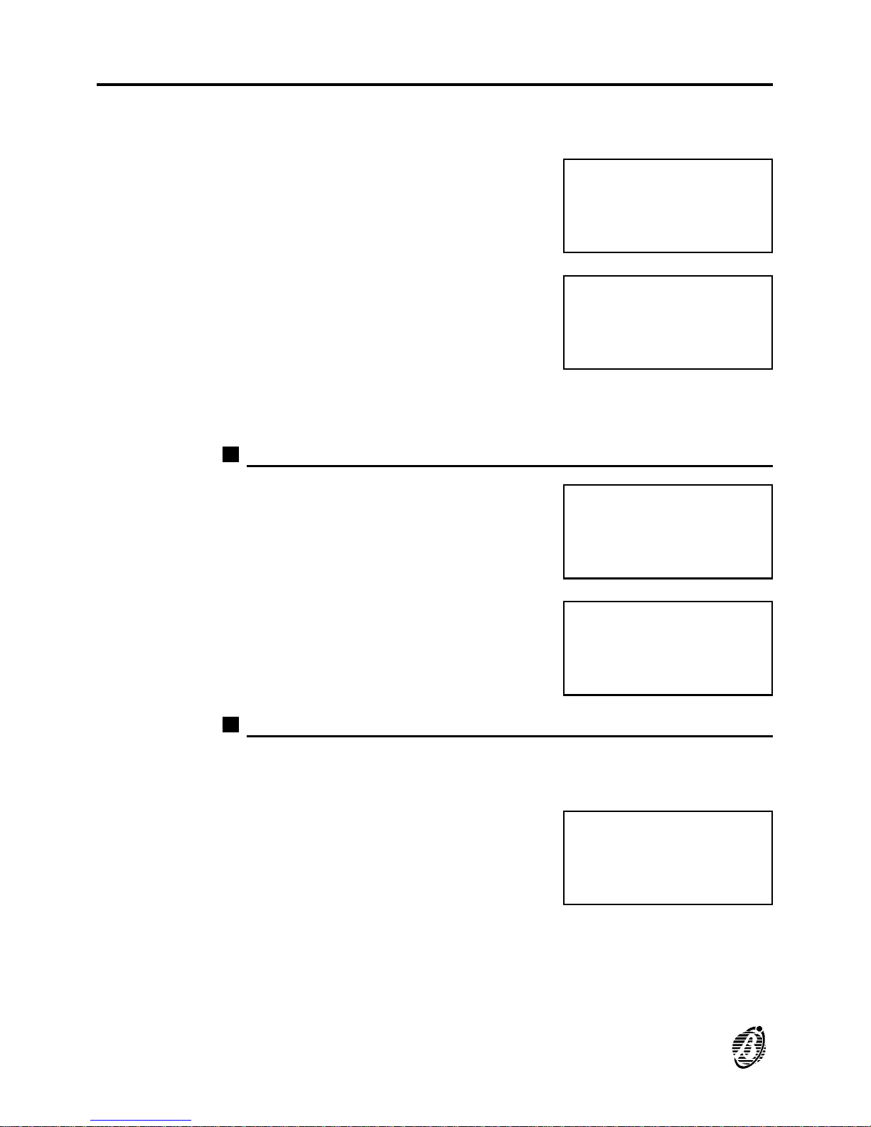
Factory
The Factory option from the PROGRAMMING menu resets the manufacturers settings (Default) on the control panel.
Select Def from the PROGRAMMING
menu (press 9).
The display will show ...
Select the required option and refer to the respective section, or press
ESC to exit and step back to the PROGRAMMING menu.
Restore default
Select the Restore default option from the
FACTORY menu (press 1).
Press the ↵ key to Restore Default settings, or ESC to exit and step back to the
FACTORY menu.
Maintenance
Select the Maintenance option from the FACTORY menu to program the
required date.
Select the Maintenance option from the
FACTORY menu (press 2).
1=Auto 2=Devices
3=PassWD 4=MesINI
5=Zones 6=Opt 7=Sys
8=Ver 9=Def Ø=Tel
PRG: FACTORY
1= Restore Default
2= Maintenance
PRG: FACTORY
1= Restore Default
2= Maintenance
PRG: FACTORY
Restore default
Are you sure ?
Yes=Enter
PRG: FACTORY
1= Restore Default
2= Maintenance
72 Analogue Fire Control Panel FireClass200
Page 73
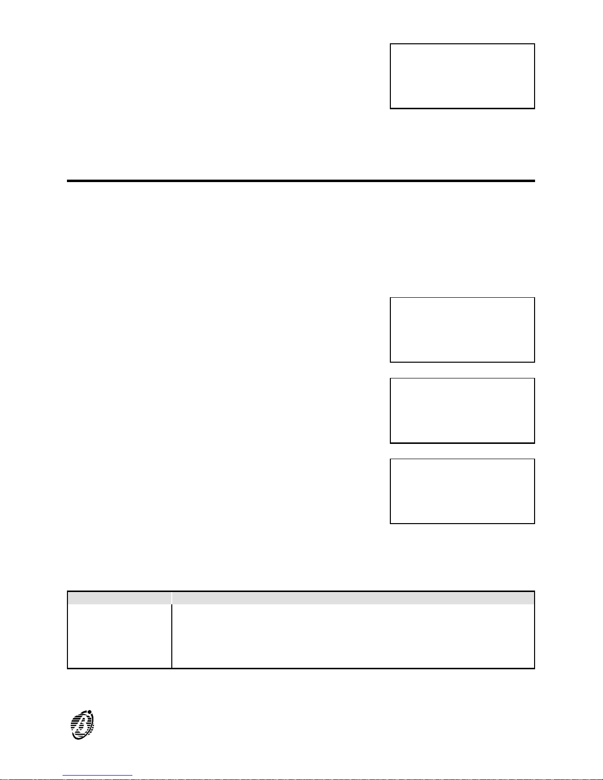
To enable the Maintenance option, select
ON and enter the date (day, month and
year). The maintenance request will be
signalled by FAULT status on the programmed date.
Press the ↵ key to confirm, or ESC to exit and step back.
Telephone
The FC200/COM Telecom module (optional) can operate as either a Dialler or Digital Communicator ---- or both. The properly programmed Telecom module will be activated by ALARM, WARNING, PREALARM and
FAULT events, and will send voice messages and/or data to the programmed telephone numbers. By entering the installer code (Factory de-
fault 00000) and pressing the ↵ key it will be possible to stop ongoing calls,
and clear the call queue.
Select the Tel option from the PROGRAM-
MING menu (press 0).
Autolearning not done ---- the display will
show the Module not present message.
Autolearning done ---- the display will
show the PRG: TELECOM MODULE
menu.
Select the required option, as per the following chart and continue, or press ESC to
step back to the PROGRAMMING menu.
KEYS OPTIONS
1 Dial.
2 Commun.
3 T.Num.
4 Option
5 Remote Management
PRG: FACTORY
Maintenance
Maintenance : OFF
on date ØØ/ØØ/ØØ
1=Auto 2=Devices
3=PassWD 4=MesINI
5=Zones 6=Opt 7=Sys
8=Ver 9=Def Ø=Tel
PRG: TELECOM MODULE
Module
not present
Esc to Quit
PRG: TELECOM MODULE
1)Dial. 2)Commun.
3)T.Num. 4)Option
5)Remote Management
PROGRAMMING 73
Page 74
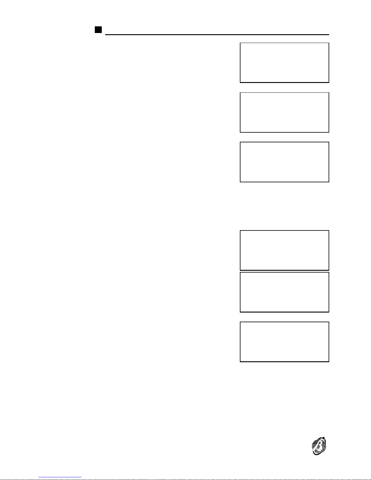
Dial. (Telephone Dialler)
Select Dial. from the PRG: TELECOM
MODULE menu (press 1) to program the
Telephone module as a Telephone dialler.
The display will show the Dialler menu.
Select Messages (press 1) to record up to
8 voice messages of 11 seconds each (1
message per channel).
Select the required message (use the ↑
and ↓ arrows) then press 6 to Record. Recording will start immediately ---- speak
clearly at about 10 cm from the microphone. The elapsing message time will be
shown on the bottom line of the display.
Listening and recording can be stopped by
pressing ESC. When the recording time
elapses the program will step back to the
PRG: Telecom Module menu.
Select the required message (use the ↑
and ↓ arrows) then press 1 to Listen.
Select Causes / Events (press 2) and assign the events to the channel / message.
The Telecom module will send the voice
messages to the programmed telephone
numbers when the assigned events occur.
Select channel 1 (press 1) and then assign the causes / events to channel
/ message 1. Repeat the procedure for the remaining channels (see figure
26). Option 3 allows up to 7 telephone numbers to be defined for each
channel (refer Tel.Num. from Dialler menu).
Press ↵ to confirm or ESC to exit.
PRG: TELECOM MODULE
1)Dial. 2)Commun.
3)T.Num. 4)Option
5)Remote Management
PRG: TELECOM MODULE
Dialler
1=Messages
2=Causes / Events
PRG: TELECOM MODULE
Dialler
Messages =
A=Listen R=Record
PRG: TELECOM MODULE
Dialler
Messages Record.=
>> >> >> >> Esc=End
PRG: TELECOM MODULE
Dialler
Messages Listening
>> >> >> >> Esc=End
PRG: TELECOM MODULE
Dialler
Causes / Events
C:1,2,3,4,5,6,7,8
74 Analogue Fire Control Panel FireClass200
Page 75
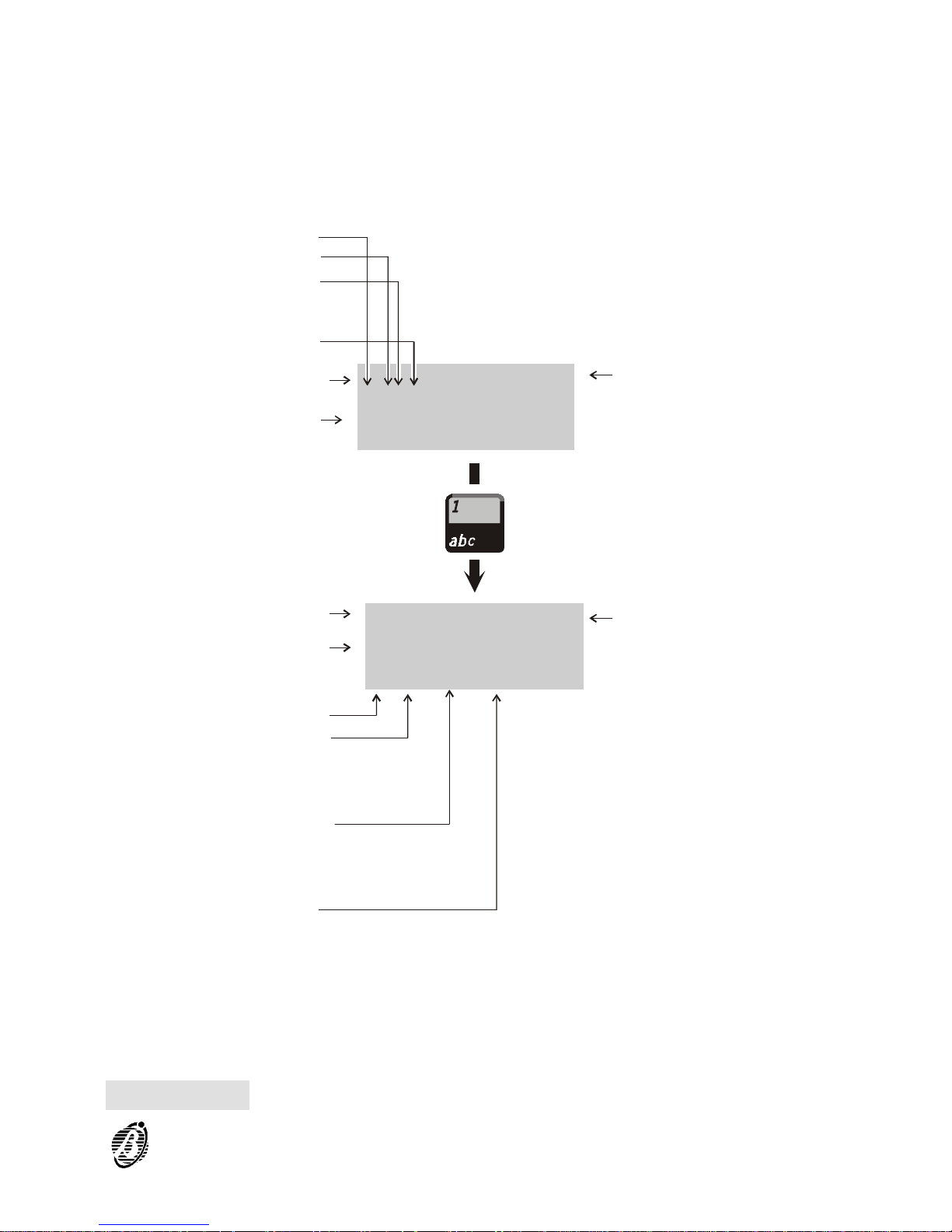
Double knock As per the same option for Output Modules (page 48).
Zone Warning As per the same option for Output Modules (page 48).
Point Warning As per the same option for Output Modules (page 48).
PRG: Dialler C= 1
N:ØØ N:ØØ N:ØØ
N:ØØ N:ØØ N:ØØ N:ØØ
G:xxx xxx xxxx
PRG: Dialler C= 1
P=1SØØ P=1SØØ P=1SØØ
Z=ØØ Z=ØØ Z=ØØ Z=ØØ
A)Attr.—>)Next
Fault:
*** = none;
Ft = Fault;
FTN = Net Fault
General conditions
Alarm:
*** = none;
AI = Alarm;
2AI = Double Alarm
Prealarm:
**** = none;
Pre = Prealarm;
PreN = Net Prealarm
Wrn = Warning;
WrnN = Net Warning;
PreZ = Prealarm zone;
WrnZ = Zone Warning;
WrnP = Point Warning
Description
Telephone numbers
connect to channels 1
1 ÷ 7
Description
a)
b)
Zones:
00 ÷ 16
Channels: 1 ÷ 8
Channels: 1 ÷ 8
Points
Loop: *; 1; 2
Type:
S = Sensor;
M = Module
Address: 00 ÷ 99
Figure 26 Input causes/events parameters
PROGRAMMING 75
Page 76
Digital Telephone Communicator (Digital Commun.)
To program the module as a Telephone
Communicator ---- select Digital Com-
mun. from the PRG: TELECOM MODULE
menu (press 2). The display will show the
Tel. Communicator menu.
The Telecom module provides 8 channels
for Telephone communicator use. Select
Codes (press 1) then select the required
channel.
.
Press ↵ to confirm and continue.
Program the selected channel, and all other channels including the Test
channel (T follows channel 8) as follows:
---- P enter the corresponding protocol number (as per below)
Protocols 1 = ADEMCO SLOW 10 BAUD
2 = ADEMCO FAST 14 BAUD
3 = FRANKLIN 20 BAUD
4 = RADIONICS 40 BAUD
5 = SCANTRONIC 10 BAUD
6 = CONTACT-ID (DTMF)
7 = SIA 300 BAUD
----User code enter the 4 digit user code (usually assigned by the central
station);
----Alm. enter the 2 digit Alarm code (usually assigned by the central station);
----Res. enter the 2 digit Restore code (usually assigned by the central station);
----Number enter 4 telephone numbers from the 32 available.
The telephone numbers must be defined in option 3 (refer to Tel.Num.
from PRG: Telecom Module menu).
PRG: TELECOM MODULE
Digital Communic.
1=Codes
2=Causes / Events
PRG: TELECOM MODULE
Digital Communic.
Codes
Channels =
PRG: T.Com.Ch.=__P=_
User Code =_____
Alm. =__ Res.=__
Number= __,__,__,__
76 Analogue Fire Control Panel FireClass200
Page 77
The Alm. and Res. codes are not required for protocol 7 SIA 300 BAUD.
The Res. code is not required for protocol 6 CONTACT-ID.
Press ↵, ESC or the arrow keys to confirm and exit.
Select Test to program the Test channel.
The display will show ....
Enter the Protocol number; the user code
and Test code (usually assigned by the
central station). Press ↵ to confirm. The
display will show ....
Enter the telephone numbers, the hour and day for the Test call.
The Test code is programmable for protocols 1 through 5 but is automatic
for protocol 6 CONTACT ID, and protocol 7 SIA 300 BAUD.
PRG: T.Com. Test P=_
User Code =____
TEST CODE__
->> Period
PRG: T.Com. Test
Number=__,__,__,__,
Hour __:__
Day = xxxxxxxx
PRG: T.Com. Ch.= 01
P=1SØØ P=1SØØ P=1SØØ
Z=ØØ Z=ØØ Z=ØØ Z=ØØ
G:xxx xxx xxxx
Fault:
*** = none;
Ft = Fault;
FtN = Net Fault
General condition
Alarm:
*** = none;
AI = Alarm;
2Al = Double Alarm
Prealarm:
**** = none;
Pre = Prealarm;
PreN = Net Warning;
Wrn = Warning;
WrnN = Net Warning;
PreZ=Prealarm Zone
WrnZ=Zone Warning;
WrnP=Point Warning
Description
Zones:
00 ÷ 16
Channels: 1 ÷ 8
Points
Loop: *; 1; 2
Type:
S = Sensor;
M = Module
Address:
00 ÷ 99
Figure 27 Digital-Communicator parameters template
PROGRAMMING 77
Page 78
Select Causes / Events from the PRG:
TELECOM MODULE menu and assign
the events to the channels (1 through 8).
The Telecom module will send the code to
the programmed telephone numbers when
the assigned events occur.
When channels (1 through 8) are programmed ---- program the corresponding parameters (see figure 27).
+
For details regarding the Double Knock, Zone Warning and Point Warning
options refer to the Output Modules section page 48.
Telephone Numbers (T.Num)
Select the T.Num. option from the PRG:
TELECOM MODULE menu, the display
will show the Telephone Numbers menu.
Use the ↑ and ↓ arrows to scroll the Number List. Select the identifier
Number (01 through 32), enter the corresponding telephone number then
press ↵ to confirm and continue. Use the ← and → arrows to scroll the
entered telephone number and delete any mistakes.
Options
Select Options from the PRG: TELECOM
MODULE menu. The display will show ...
Sel Select Pulse or DTMF, according to local requirements. The Telecom
module is programmed to dial in DTMF (factory default). However, if both
modes are available select DTMF as it is faster.
C.D.T. If the Check Dial Tone option is disabled OFF ---- the telecom module will
dial the programmed telephone numbers assigned channel in alarm status,
without checking for the dialling tone.
If the Check Dial Tone option is enabled ON ---- the telecom module will
will dial the programmed telephone numbers only when the dial-tone is
detected, otherwise, it will release the telephone line and restart the alarm
cycle from the same telephone number: after 4 attempts the Telecom module will exit and step to the successive telephone number.
The control panel comes with the Check Dial Tone option enabled (ON).
PRG: TELECOM MODULE
Digital Communic.
Causes / Events
C:1,2,3,4,5,6,7,8
PRG: TELECOM MODULE
Telephone Numbers
Number : __
____________________
PRG: TELECOM MODULE
OPTION Tel.
Sel=_C.D.T.=___RT=_
AK=___J=___ C/R_/_
78 Analogue Fire Control Panel FireClass200
Page 79

+
This option must be disabled during the test phase (telephone line disconnected), and also when the telecom module is connected to telephone networks with non-standard tones.
RT The Telecom module will answer after the number of rings programmed for
Ringing Tones option.
AK The Acknowledge option allows 3 different operating modes:
Ø SN (Successful Numbers): the control panel will perform the alarm cycle
and check whether calls are successful or not, and will redial the telephone numbers of successful calls during the subsequent cycles.
Ø NSN (No Successful Numbers): the control panel will perform the alarm cy-
cle and check whether calls are successful or not, but will not redial the
telephone numbers of successful calls in the subsequent cycles.
Ø PS (Play Systematically) the Answer Check will be disabled and the mes-
sage will be played 5 seconds after dialling.
J The Jump (Double Call / Jump other answering devices) option allows the
control panel (via Telecom module) to share the telephone line with one or
more answering devices (answerphone, fax, etc.). In normal circumstances
the device programmed with the least number of rings will answer, however, if the J option is enabled (ON) the Telecom module will override the
other answering devices when it recognizes the double call sequence.
Double call sequence: the user must call the control panel, allow 2 rings
then hang up and recall within 60 seconds. The control panel will not answer the first call but will answer on the first ring of the second call. If more
than 60 seconds elapse ---- the Double call sequence will not be recognized and it will be necessary to retry.
+
The other answering device must be programmed to answer after 3 rings
or more.
+
If the Jump option is enabled the RT (Ring Tone) option can be ignored.
The Telecom module comes with the Jump option disabled (OFF).
C/R This is for the number of Cycles (1 to 8), and for the Repetition time (the
time the message must be played for each telephone number). To program the Messages playback time select:
1 = 20 seconds
2 = 40 seconds
3 = 60 seconds
4 = 80 seconds
5 = 100 seconds
Press ↵ or ESC to confirm and exit.
.
PROGRAMMING 79
Page 80

Remote management
Select Remote management from the
PRG:TELECOM MODULE menu (press
5) to enable (ON) or disable (OFF) Tele-
service. When the Teleservice option is
ON the installer will be able to service the
control panel, and change the parameters
via telephone. When Teleservice is OFF
this will not be possible. The installer must
be equipped with the optional OMNIAMOD/V1 or OMNIAMOD/V2, and the
respective software in order to provide this
service.
PRG: TELECOM MODULE
Remote Managem.=OFF
80 Analogue Fire Control Panel FireClass200
Page 81
MODIFYING
The Modifying option from the MAIN menu allows the user to: disable the
devices connected to the control panel; delete the Verify counters and log;
modify some of the parameters of the Telecom module.
Select the Modifying option from the
MAIN menu (press 2).
Enter the user code (the default code is
11111) each digit will be masked by the
symbol Q.
Press the ↵ key to confirm the code. If the
code is valid the display will show the
MODIFYING menu.
Select the required option and refer to the respective section or press ESC
to step back to the MAIN menu.
Wrong code If a wrong code is entered, the display will
request Retry.
User default
code
The user default code is 11111. The user default code may be changed by
means of the PassWD option from the PROGRAMMING menu.
FIRE CLASS 2ØØ
1= Programming
2= Modifying
3= Reading Parameter
Enter
user
code
*****
Modifying:
1=Disable
2=Del.Ver.3=Del.Log
4=Telecom Module
User code
Wrong !
Retry
XXXXX
MODIFYING 81
Page 82

Disable
The Disable option from the MODIFYING menu can disable or Enable:
Ø the loop devices (input or output devices);
Ø Bell Outputs;
Ø Software Zones;
Ø Devices on the Network (repeater panels or slave panels).
The DISABLE LED will go ON when one or more of the above mentioned
is/are disabled.
The disabled and enabled modes are as follows.
Input Devices A disabled input device (Detector, Input module, Conventional Zone mod-
ule, Addressable Call-points) will not generate ALARM or FAULT status.
Ø To clear FAULT status generated by an input device - Disable the input
device concerned.
Ø To clear ALARM status generated by a input device - RESET the control
panel.
+
Input devices enabled during ALARM or FAULT status will generate the
status, as necessary.
Output Devices ALARM or FAULT status will not activate disabled output devices (Output
modules, Addressable Sirens).
Ø To stop the output devices activated by FAULT status - Disable the de-
vices concerned.
Ø To stop the output devices activated by an ALARM status - RESET the
control panel.
+
Output devices enabled during ALARM or FAULT status, will be activated
immediately.
Bell Outputs The enabled and disabled operating modes of the Bell Outputs are as per
output devices.
Software Zones The disabled or enabled mode of a software zones will effect all its associ-
ated devices, as previously described.
Repeaters A disabled repeater panel cannot command the Master control panel, al-
though, its display will show the Master panel status. FAULT status will be
generated when a repeater panel is Not Found. Loss of a disabled repeater panel will not generate a FAULT status.
Ø To clear a FAULT status - generated by the loss of a Repeater - Disable
the repeater panel concerned.
82 Analogue Fire Control Panel FireClass200
Page 83
+
FAULT status will be generated when the repeater panel is re-enabled.
Slave panels A disabled slave panel cannot generate NETWORK ALARM or NETWORK
FAULT status. Loss of disabled slave panel from the Network will not generate FAULT status.
Ø To clear FAULT status - generated by the loss of a slave panel - Disable
the slave panel concerned.
Ø To clear a NETWORK FAULT - generated by a slave panel - Disable the
slave panel concerned.
Ø To clear a NETWORK ALARM status generated by a slave panel - RESET
the Master panel.
+
FAULT status will be generated when the slave panel (in FAULT status) is
re-enabled.
+
NETWORK FAULT status will be generated when the slave panel (in NETWORK FAULT status) is re-enabled.
Procedure Proceed as follows to disable the Control panel items: Loop devices; Bell
Outputs; Software Zones; Network devices.
1. Select the Disable option from the MODI-
FYING menu (press 1).
2. Select the required item, or press ESC to
step back to the MODIFYING menu.
3.
Enter the Item address then press the ↵
key, or press ESC to step back and select
another Item.
If a valid Item address is entered the display will show the: Item label;
real-time Analogue Value; type; address; current status (see figure 28).
4.
Press the ↑ or ↓ key to change the Item
status then press the ↵ key to confirm or
ESC to exit.
Modifying:
1=Disable
2=Del.Ver.3=Del.Log
4=Telecom Module
MOD: Enab./Disabl.
1=LOOP 1 2=LOOP 2
3=Outputs BELL
4=ZONES 5=NET 6=TEL
MOD: Devices L1
Enter Address
Sensors L1: 1/##
Modules L1: 1/__
MOD: Enab./Disabl.
Device: SENSOR
%## 1/##
STATUS: DISABLED
MODIFYING 83
Page 84
5. Step back to 3.
Conventional
line
To enable or disable the Conventional line
(terminal 10[LC+]): position the cursor on
the L1 Detector space and press the ↑
key.
Non-Configured
Devices
If an invalid address is entered, the display
will show an error message. Press ESC to
exit and step back to 3.
Delete Verify
The Delete Verify option from the MODIFYING menu clears the Verify
Counter of each detector.
Select the Delete Verify option from the
MODIFYING menu (press 2) to clear ALL
the Verify Counters.
Press the ↵ key to clear all the Verify
Counters, or ESC to exit and step back to
the MODIFYING menu.
MOD: Devices L1
Enter Address
Sensors L1: 1/ZC
Modules L1: 1/__
DEVICES LOOP1
Device not
configured
on LOOP 1
Modifying:
1=Disable
2=Del.Ver.3=Del.Log
4=Telecom Module
MOD: Clear Verify
Are
you sure ?
Yes=Enter No=Esc
Figure 28 Enabled/Disabled status of detectors
84 Analogue Fire Control Panel FireClass200
Page 85
Delete Log (Del. Log)
The Delete Log (Del. Log) option from the MODIFYING menu deletes the
contents of the log.
Select the Delete Log (Del. Log) option
from the MODIFYING menu (press 3).
Press the ↵ key to delete the log, or press
ESC to exit and step back to the MODIFYING menu.
Telecom Module
Select the Telecom Module option from
the Modifying menu (press 4) to change
the telephone numbers and messages,
and to enable /disable the Remote man-
agement option. The display will show ...
Select Numbers (press 1) to change the
programmed telephone numbers.
Select the identifier number (1 to 32) of the
telephone number concerned, and change
as required.
Select Messages (press 2) to change, record and/or listen to the messages.
Enter the identifier number of the message
and press 1 to listen. The display will show
...
Modifying:
1=Disable
2=Del.Ver.3=Del.Log
4=Telecom Module
Mod: Clear Log Ar
e yo
u sure ? ye
s=Enter NO=Esc
Modifying:
1=Disable
2=Del.Ver.3=Del.Log
4=Telecom Module
Mod: Telecom Module
1=Telephone Numbers
2=Messages
3=Remote Management
Mod: Telecom Module
Telephone Numbers
Number = 01
____________________
Mod: Telecom Module
Message =
A = Listen
B = Record
Mod: Telecom Module
Listen
Message = 1
>>>>>>> Esc=End
MODIFYING 85
Page 86
Press ESC to stop the message and step
back. Select Record (press 6) to record or
change messages.
Select Remote Management (press 3) to
enable / disable Teleservice (ON/OFF).
Mod: Telecom Module
Recording
Message = 1
>>>>>>> Esc=End
Mod: Telecom Module
Remote Managem. =OFF
86 Analogue Fire Control Panel FireClass200
Page 87
READING PARAMETER
Use the Reading Parameter option from the MAIN menu to view all the
control panel parameters, and to print the log contents.
Select the Reading Parameter option
from the MAIN menu (press 3). No access
code is required, as viewing and printout
do not effect the parameters and operating
modes of the control panel.
The display will show the READING PA-
RAMETER menu.
Select the required option and refer to the respective section, or press
ESC to step back to the MAIN menu.
Devices/Zones/Outputs
The Dev./Zones/Outputs option from the READING PARAMETER menu
shows the parameters of the devices connected to the Loops, Software
Zones, Bell Outputs, and of the devices on the network.
1. Select the Dev./Zones/Outputs option
from the READING PARAMETER menu
(press 1) or press ESC to step back to the
MAIN menu.
2. Select the required option or press ESC to
return to the READING PARAMETER
menu (step 1.).
3. Enter the address of the required Item.
Press ESC to step back to the
Dev./Zones/Network (step 2.).
FIRE CLASS 2ØØ
1= Programming
2= Modifying
3= Reading Parameter
READINGS:
1=Dev./Zones/Outputs
2=Opt.3=Ver.4=Log.
5=Print 6=M.Telecom
READINGS:
1=Dev./Zones/Outputs
2=Opt.3=Ver.4=Log.
5=Print 6=M.Telecom
RD: Choosing Menu
1=LOOP 1 2=LOOP 2
3=Outputs BELL
4=ZONES 5=NET
RD: Devices L1
Enter Address
Sensors L1: 1/##
Modules L1: 1/__
READING PARAMETER 87
Page 88
+
Position the cursor on loop 1 then press the ↑ key to view the parameters
of the Conventional Line.
If a valid address is entered the display will show the respective data as
described in the "PROGRAMMING".
Press the ← or → key to view the parameters of the other Items of the
same type, or press ESC to enter another address (step 3.).
If an invalid address is entered at step 3.,
the display will show the Device not con-
figured message. Press ESC then retry.
Options
This option from the READING PARAMETER menu shows the parameters of the Options.
Select Options from the READING PA-
RAMETER menu (press 2), or press ESC
to step back to the MAIN menu.
The display will show the OPTIONS menu
(refer to the OPTIONS section). Press
ESC to step back to the READING PARAMETER menu.
Version
The Version option from the READING PARAMETER menu shows the
control panel version.
Select the Version option from the VIEW
PARAMETERS menu (press 3), or press
ESC to step back to the MAIN menu.
DEVICES LOOP1
Device not
configured
on LOOP 1
READINGS:
1=Dev./Zones/Outputs
2=Opt.3=Ver.4=Log.
5=Print 6=M.Telecom
RD: OPTIONS
Ø=P 1=W 2=V 3=D 4=T
5=S 6=H 7=D 8=Pulse
9=Extinction Mode
READINGS:
1=Dev./Zones/Outputs
2=Opt.3=Ver.4=Log.
5=Print 6=M.Telecom
88 Analogue Fire Control Panel FireClass200
Page 89
The display will show the control panel
version. Press ESC to step back to the
READING PARAMETER menu.
Log
The FireClass200 Log stores 200 events. When the log is full the oldest
events will be deleted automatically to make space for the new events.
1. Select the Log option from the READING
PARAMETER menu (press 4), or press
ESC to step back to the MAIN menu.
2. The display will show the most recent
event.
N.B. The example shows no.123 as being
the most recent event.
3.
Press the ← to scroll back.
4.
Press the → key to scroll forward.
5. Press ESC to exit and step back to READINGS menu.
When the ← key is pressed on the oldest
event ...
Fire Class 2ØØ
version
3.Ø
READINGS:
1=Dev./Zones/Outputs
2=Opt.3=Ver.4=Log.
5=Print 6=M.Telecom
ZONE ALARM 123
FIRE CLASS 2ØØ
Software Zone
15:Ø9 13/Ø7/99 Ø1
ALARM 122
FIRE CLASS 2ØØ
Device: MODULE
15:Ø9 13/Ø7/99 1M13
ZONE ALARM 123
FIRE CLASS 2ØØ
Software Zone
15:Ø9 13/Ø7/99 Ø1
FAULT ØØØ
FIRE CLASS 2ØØ
Missing MAIN
18:Ø2 Ø5/Ø7/99
READING PARAMETER 89
Page 90
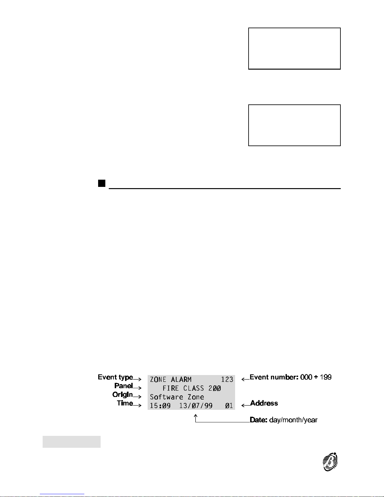
... the most recent event will be shown.
When the → key is pressed on the most recent event, the control panel will
emit an error signal.
No event At step 2. - if the log is empty (no events)
the display will show the LOG EMPTY
message.
Delete Log Use the Delete Log option in the MODIFYING menu to delete the log con-
tents.
Log data
The following data is stored in the log (see fig. 29).
Event Type This is the description of the event.
Event Number This is the event number from 1 through 200.
Panel This is the control panel label (Master panel, slave panel or repeater panel)
assigned during programming.
Origin This is the label of the Item which generated the event.
Hour/Date This is the exact time and date of the event.
Address This is the address of the Item which generated the event.
ZONE ALARM 123
FIRE CLASS 2ØØ
Software Zone
15:Ø9 13/Ø7/99 Ø1
ØØØ
LOG
EMPTY
Figure 29 Log data
90 Analogue Fire Control Panel FireClass200
Page 91
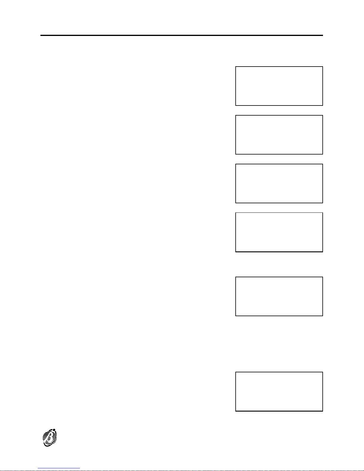
Print
The Print option from the READINGS menu prints all the log contents on
the connected printer.
1. Select the Print option from the READ-
INGS menu (press 5) or press ESC to step
back to the MAIN menu.
2. Select the Log option (press 1) or press
ESC to step back the READINGS menu.
3.
Press the ↵ key to start the Log printout or
press ESC to exit and step back to 2.
4. The display will show ...
+
The control panel will continue functioning during the log printout.
Printer not
enabled
The printer must be enabled, otherwise, at
step 4. the display will show ...
Printer not
connected
The serial printer must be connected to the serial port of the control panel.
The control panel will not signal Printer not connected and/or Printer not
ready (paper out, no ink or blocked etc.) conditions.
Stop Print To stop Print - proceed as per start Print.
At step 3. press ↵, the display will show ...
READINGS:
1=Dev./Zones/Outputs
2=Opt.3=Ver.4=Log.
5=Print 6=M.Telecom
READINGS
Print:
1= Log 2=
Programming
Log Print Sta
rt Print ? Ent
er = Yes Esc
= Exit
Log Print
running
please
wait....
Printer not
enabled !
Enable in
menu’ PRG:SYSTEM
Log Print
running
SUSPEND ?
Yes = Enter
READING PARAMETER 91
Page 92
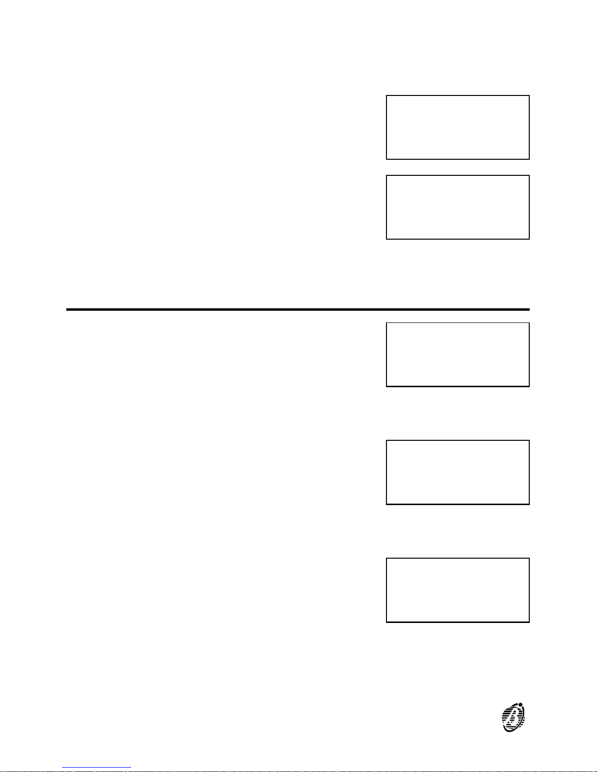
Press the ↵ key to suspend the Print or press ESC to go back to step 3.
Print
Programming
The Programming option from the PRINT menu is reserved for future use.
If the Programming option is selected from the PRINT menu.
The display will show ...
Press ESC to step back to the PRINT menu (step 2.).
Telecom Module
Select the Telecom Module option from
the PARAMETER READING menu to
view the Telecom module settings.
Select Tel.Mod. from the PARAMETER READING menu (press 6), or
press ESC to step back to the Main menu.
The display will show ...
Select Telephone numbers (press 1) to view the programmed Telephone
numbers (01 to 32).
The display will show ...
READINGS
Print:
1= Log 2=
Programming
Programming Data
Print
Future Use
Future Use
READINGS:
1=Dev./Zones/Outputs
2=Opt.3=Ver.4=Log.
5=Print 6=M.Telecom
Rd. :Telecom Module
1=Telephone Numbers
2=Messages
3=Management
Rd. :Telecom Module
Telephone Numbers
Number : 01
___________________
92 Analogue Fire Control Panel FireClass200
Page 93

Select Messages (press 2) to listen to the
messages recorded during the programming phase of the Telecom module.
Select Remote management (press 3) to enable or disable (ON / OFF)
Teleservice.
The display will show ...
Rd. :Telecom Module
Message = 1
A = Listen
Rd. :Telecom Module
Management
STATE:_____________
Remote Managem.= OFF
READING PARAMETER 93
Page 94

94 Analogue Fire Control Panel FireClass200
Page 95
QUICK GUIDE
This quick guide holds all the information required by installers with some
knowledge of the FireClass200 fire control panel, or of fire control panels in
general.
General features
Below are some of the technical features of the terminals on the Main
board, Output Expanders and Repeaters.
FireClass200
FC200 FC200/S-FC100
Mains Voltage (1)
117 V 50-60 Hz ±10%
230 V 50-60 Hz ±10%
Maximum current 1.3 A @ 117 V
0.9 A @ 230 V
1.0 A @ 117 V
0.7 A @ 230 V
Maximum current available (2) 2 A 1 A
Low voltage range
19.0 ÷ 27.6 V
Low voltage ripple 1 %
Battery type:
make
model
two 12 V - 17 Ah
YUASA
NP 17-12 FR
or the equivalent with case flame class
UL94-V2 (or over)
Temperature range
-5 ÷ +40 °C
Dimensions (L*H*P) 432*577*131 mm
Max. weight (3) 21 Kg
(1) As per the local Mains power voltage.
(2) For the power supply to external devices.
(3) With two 12 V - 17 Ah batteries.
Repeater
Mains voltage 27.6 V
Maximum current 180 mA
Temperature range
-5 ÷ +40 °C
Dimensions (L*H*P) 195*178*45 mm
Weight 1.1 Kg
QUICK GUIDE 95
Page 96
Terminals
The following charts hold:
Ø a brief description of the terminals on the Main Board, Output Expanders
and Repeaters;
Ø the voltage present during the different conditions of each terminal;
Ø the maximum voltage (in amperes) that can circulate on each terminal.
Main board
TERM. DESCRIPTION v(V) i(A)
[L1B] LOOP 1 IN -- -[L1A] LOOP 1 OUT -- -[L2B] LOOP 2 IN -- -[L2A] LOOP 2 OUT -- --
[LC+]
CONVENTIONAL LINE:
balanced line with 2700 ohm è control panel in standby
unbalanced line è Conventional Zone activated
line in short-circuit or open è fault on the Conventional Zone
-- --
[EX] RESERVED OUTPUT -- --
[+485--] SERIAL BUS -- --
14[ ] 17[+]
REPEATER POWER SUPPLY:
negative present on terminal 14[ ]
positive present on terminal 17[+]
0
27.6 3 (3)
[AUX]
24 V AUXILIARY POWER SUPPLY:
negative present on terminal 19[ ]
positive present on terminal 19[+]
0
27.6 3 (3)
[CM1]
[NC1]
[NO1]
FAULT ALARM OUTPUT - NON Controlled:
standbby è [CM1] connected to [NC1] with [NO1] open
in the event of fault è [CM1] connected to [NO1] with [NC1] open
-- 5
[CM2]
[NC2]
[NO2]
FIRE ALARM OUTPUT - NON Controlled:
standby è [CM2] connected to [NC2] with [NO2] open
in ALARM Status è [CM2] connected to [NO2] with [NC2] open
-- 5
[C]
POSITIVE FIRE ALARM OUTPUT - Controlled:
in ALARM Status è positive on [+] and negative on [--] 27.6 1.5 (3)
[C2] [C3]
[C4]
PROGRAMMABLE OUTPUTS - Controlled:
output active è positive on [+] and negative on [--] 27.6 1.5 (3)
[REM]
LOGIC UNIT BLOCKED:
Logic Unit blocked è terminal to negative 0 1
[DEF]
DEFAULT DATA:
Control panel programmed with default data è terminal to negative 0 1
[OC1]
↓
[OC16]
ZONE ALARM:
corresponding zone in standby è terminal open
zone in ALARM Status è terminal to negative
0 0.1
36-45[ ]
GROUND
0 --
96 Analogue Fire Control Panel FireClass200
Page 97
Output Expander
TER. DESCRIPTION v(V) i(A)
[C5/11]
↓
[C10/16]
PROGRAMMABLE OUTPUTS - Controlled:
output active è positive on [+] and negative on [--]
27.6 1.5 (3)
Repeater
TER. DESCRIPTION v(V) i(A)
[+485--] SERIAL BUS -- --
1[ ]
4[24V]
POWER SUPPLY (input):
terminals for the power supply to the Repeater
27.6 0.18
5[ ]
8[24V]
POWER SUPPLY (output):
terminals for the power supply to the next Repeater
-- --
19[+] POSITIVE 27.6 0.2
[Z1]
↓
[Z16]
ZONE ALARM:
zone in standby è corresponding terminal open
zone in ALARM Status è corresponding terminal to negative (4)
-- 0.01
Telecom Module
TER. DESCRIPTION v(V) i(A)
[LE1]
[LE2]
TERMINALS FOR THE CONNECTION of the external telephone
lines
/ /
[LI]
TERMINALS FOR THE CONNECTION of other telephone-line
sharing devices (answerphone, telephone, fax modem, etc.)
/ /
[ ]
Earth Terminal
0 /
(3) The total current absorbed by terminals 17[+], 19[+], 26[+], 28[+], 30[+],
32[+] on the Main Board, and by terminals [+] of the Output Expander,
must not exceed:
2 A for the FC200 control panel;
1 A for the FC200/S - FC100 control panel.
(4) Terminals from [Z1] to [Z16] of the Repeater must be connected to nega-
tive by a 2700 ohm resistance, and asbsorb 0.01 A in the connection to a
LED.
QUICK GUIDE 97
Page 98

Notes
___________________________________________________________
___________________________________________________________
___________________________________________________________
___________________________________________________________
___________________________________________________________
___________________________________________________________
___________________________________________________________
___________________________________________________________
___________________________________________________________
___________________________________________________________
___________________________________________________________
___________________________________________________________
___________________________________________________________
___________________________________________________________
___________________________________________________________
___________________________________________________________
___________________________________________________________
___________________________________________________________
___________________________________________________________
___________________________________________________________
___________________________________________________________
___________________________________________________________
___________________________________________________________
98 Analogue Fire Control Panel FireClass200
Page 99

Notes
___________________________________________________________
___________________________________________________________
___________________________________________________________
___________________________________________________________
___________________________________________________________
___________________________________________________________
___________________________________________________________
___________________________________________________________
___________________________________________________________
___________________________________________________________
___________________________________________________________
___________________________________________________________
___________________________________________________________
___________________________________________________________
___________________________________________________________
___________________________________________________________
___________________________________________________________
___________________________________________________________
___________________________________________________________
___________________________________________________________
___________________________________________________________
___________________________________________________________
QUICK GUIDE 99
Page 100

ISTINSFC200/UK 1.0 301105 BUI V4.2
 Loading...