

Page 1

3.50
ISO 9001
9105.BNT1
ISO 9001
IT-52587
OHSAS 18001
9192.BSEC
OHSAS 18001
IT - 60983
ISO 14001
9191.BNT2
ISO 14001
IT-52588
www.bentelsecurity.com
https://itunes.apple.com
https://play.google.com/store
*
EN50131 Grade 2 and Grade 3**
Expandable Hybrid Control Panel
Installer Manual
Default Installer PIN: (A)0104 (00104 for Grade 3 Control Panels)
Page 2

Always use the most recently BOSS Console Software to program the ABSOLUTA.
Installation of the system must be carried out strictly in accordance with the instructions described in this manual, and in
compliance with the local laws and bylaws in force.
The GSM, ABS-GSM and IP, ABS-IP modules must be installed by Service Persons only (service person is defined as a
person having the appropriate technical training and experience necessary to be aware of hazards to which that person may be
exposed in performing a task and of measures to minimize the risks to that person or other persons).
The GSM, ABS-GSM and IP, ABS-IP modules must be installed and used within an environment that provides the pollution
degree max 2, over voltages category II, in non-hazardous, indoor locations only.
All instructions specified within thIS manual must be observed.
The ABSOLUTA Control Panels have been designed and manufactured to the highest standards of quality and performance.
The ABSOLUTA Control Panels have no user-changeable components, therefore, they should be serviced by authorized
personnel only.
BENTEL SECURITY does not assume responsibility for damage arising from improper application or use.
The manufacturer recommends that the installed system should be completely tested at least once a month.
Hereby, BENTEL SECURITY, declares that ABSOLUTA Control Panels comply with the essential requirements and other
relevant provisions of Directive:
2006/95/EC The Low Voltage Directive
2004/108/EC The Electromagnetic Compatibility Directive
99/55/EC The R&TTE Directive
This panel complies with EN50131-1: 2008, EN50131-3: 2009 and EN50131-6: 2008
MAINTENANCE
Please verify the correct operation of security system at least once a month.
Periodically, perform the steps below.
— Remove dust accumulation on the panel container, with a damp cloth without use any type of solvent.
— Check the status of the connections and wires.
— Check inside the panel there are no foreign bodies.
— For other security-system devices, such as smoke detectors, infrared and microwave detectors, and inertial detectors, refer
to the instructions for maintenance and testing.
RECYCLING INFORMATION
BENTEL SECURITY recommends that customers dispose of their used equipments (panels, detectors, sirens, and other
devices) in an environmentally sound manner. Potential methods include reuse of parts or whole products and recycling of
products, components, and/or materials.
For specific information see: http://www.bentelsecurity.com/index.php?o=environmental
WASTE ELECTRICAL AND ELECTRONIC EQUIPMENT (WEEE) DIRECTIVE
In the European Union, this label indicates that this product should NOT be disposed of with household waste. It should
be deposited at an appropriate facility to enable recovery and recycling.
For specific information see: http://www.bentelsecurity.com/index.php?o=environmental
BENTEL SECURITY srl. reserves the right to change the technical specifications of this product without prior notice.
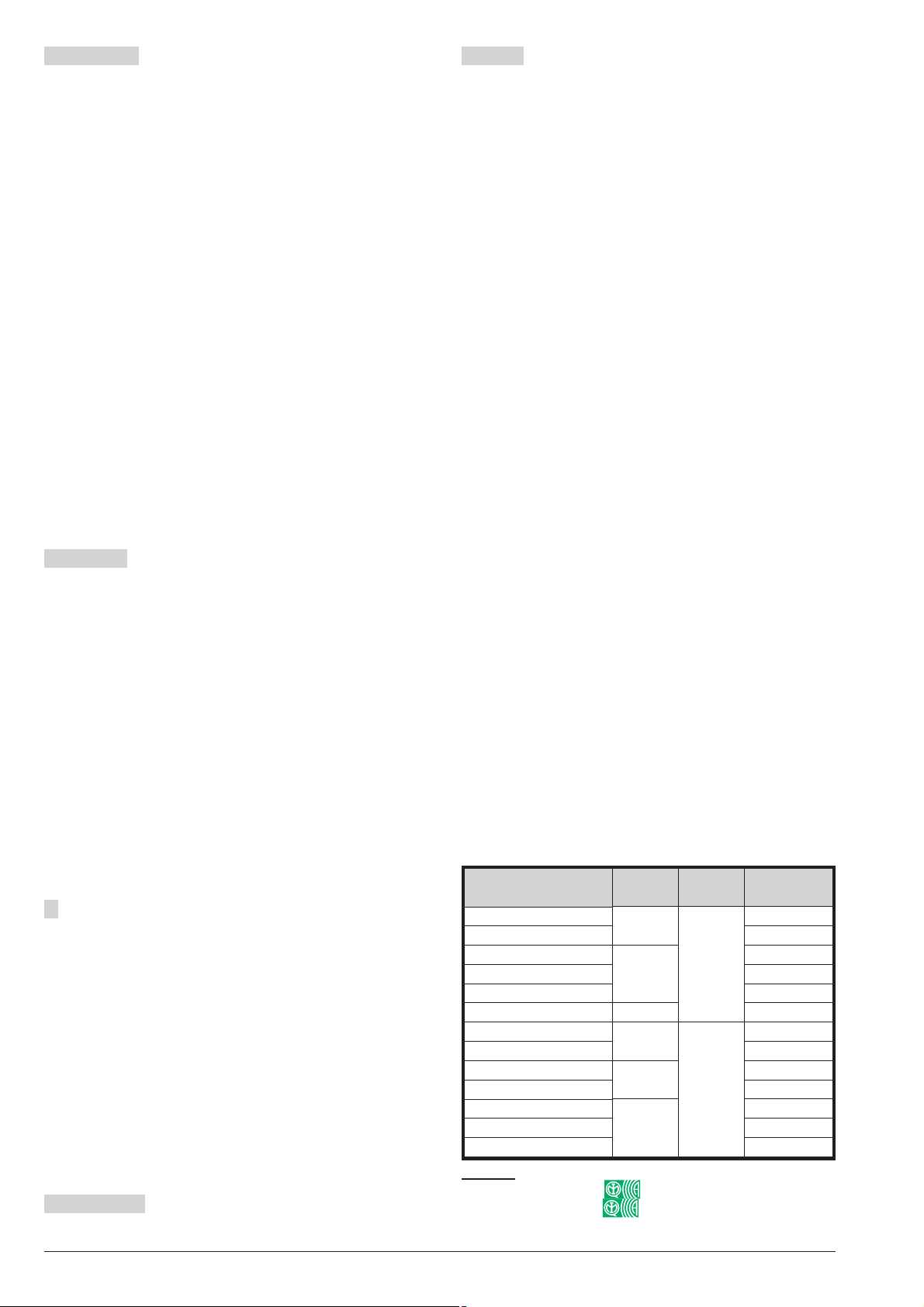
*) See Table 2 on page 7.
**)See Table 2 on page 7.
Page 3

TABLE OF CONTENTS
INTRODUCTION 5
About the Control Panel 5
Features 6
Common Features for all versions 6
ABSOLUTA 16 features 7
ABSOLUTA 42 features 7
ABSOLUTA 104 features 7
Control Panel versions 8
Grade 3 Control Panels 8
The boxes 8
The Main Boards 9
The Power Supplies 9
The Accessories 9
Plug-In Modules 9
Compatible items 10
Access Levels for panel management 11
Updates 12
3.50 Grade 3 12
3.50 12
3.00 12
2.10 12
Technical Specifications 13
INSTALLING 25
Mounting the Control Panel 25
Mounting the BPI Peripherals 25
Terminals 25
Wiring 27
Connecting BPI Bus Devices 27
BPI bus Wiring Limitations 28
Connecting Detectors 28
Connecting Motion Detectors 29
Connection of Grade 3 detectors 30
Connecting Roller-Blind and Vibration Detectors
Connecting Fire Detectors 31
Connecting Alarm Signalling Devices 32
Supervised Output 33
Connecting Tamper Terminals 33
Connecting the Telephone Line 34
Connecting the AS100 Audio Station 35
Power Supply 35
Power connection 36
Power disconnection 36
Auto-configuration (Wizard setup) 36
Thermal Probe 38
Hardware Default 38
31
IDENTIFICATION OF PARTS 15
MOUNTING THE COMPONENTS 19
Mounting the Metal Box 19
Mounting the Plastic Box 20
Installing the GSM Module 22
Installing the IP Module 23
Page 4

PROGRAMMING FROM THE PC 39
Options with requirements 39
Minimum system requirements 39
Configuration 40
Keypads 40
Expander In 41
Expander Out 41
Key Readers 41
Power station 41
Wireless Module 43
Zones 43
Partitions 48
Phonebook 50
Audio Session 50
Priority 51
Outputs 51
Voice Messages 53
System Options 53
General 53
Time Options 56
Received Call 56
Phone Options 56
Advanced Call Options 58
EN50131 59
Installer 59
Events and Actions 59
OUTPUTS ACTIVATION 59
VOCAL ACTIONS/AS100 - CALLS 59
SMS 60
CENTRAL STATION ACTIONS 61
Event Description 62
Remote Command Events 62
Caller ID over GSM events 63
Default settings 63
Smart Actions 70
Smart SMS 70
Emails 72
APP Notification 72
Emails 73
Addresses 73
Partitions 73
Codes and Keys: User (PINs) 73
Codes and Keys: Keys 75
Codes and Keys: Keyfobs 76
Arming Schedule 77
Time Table 77
Partitions Event Editor 77
Perpetual Calendar 77
Timers 78
Time Table 78
Timer Event Editor 78
Perpetual Calendar 78
GSM 78
Pay As You Go 79
App/BOSS Cellular Communication 79
Cellular 79
Disabling event transmission to the receivers 80
IP 81
SMS Messages 83
Downloading/Uploading 83
Connecting the Control Panel to the PC 83
How Downloading/Uploading the Options 86
KEYPAD OPERATIONS 87
Using the keypad 87
Access to the operations 88
Quit from the Operations 90
1.1) Zone Test 91
1.2) Output Test 92
1.3) Changing the PIN 92
1.4) Firmware Upgrade by an USB key 93
1.6) Modify the Keypad language 94
1.7) Enabling Level 4 access 94
1.8) Clear Faults and Tampers 95
1.9) Option Programming by Keypad 95
Zones 95
Partition 96
User PINs 96
Keys 96
WLS Keys 96
System 97
Key Reader 97
Keypad 97
2.1) Voice Message Recording 97
2.2) BPI Device enrolling 98
2.3) Wireless Device enrolling 98
2.4) Key enrolling 99
2.5) Message Download/Upload via USB Key 100
2.6) Option Download/Upload via USB Key 100
2.7) Factory Default 101
2.8) Telephone Communicator 101
2.9) Key Disabling/Enabling 102
3.1) View Logger 102
3.2) View the Firmware Version 103
3.3) View Zone Status and Zone Bypassing 103
3.4) View GSM Module Status 104
3.5) View IP Module Status 105
APPENDIX 107
Quick guide for the LCD Keypad menu 107
Zone Automapping 107
Reporting Formats 108
Contact ID 108
SIA 108
Wireless Receivers 111
Identification of Parts 111
Choosing a Mounting Location 111
Mounting the Receiver 111
Connecting the Receiver 111
Technical Specifications 111
Connection via IP 112
Local IP connection (LAN) 112
Remote IP Connection (Internet) 112
Page 5

INTRODUCTION
About the Control Panel
The full-featured ABSOLUTA security systems have
been especially designed to satisfy all security needs,
from residential to advanced industrial applications.
The objective of the ABSOLUTA is to make end-user
operation simple and help the Installer improve effi
ciency. This is achieved by reduced complexity soft
ware and firmware, and remote programming and
diagnostic facilities.
This system provides impressive application flexibility
and many interesting features such as monitoring facili
ties and telephone access.
The ABSOLUTA range of panels is composed of three
main models based on a common platform.
ABSOLUTA 16 Expandable up to 16 hardwired zones
or 32 wireless zones. This Control Panel is dedicated to
the basic applications for residential and small commercial sectors.
ABSOLUTA 42 Expandable up to42 hardwired zones.
This panel is dedicated to the middle-high level applications for the residential sector and to the middle level installation for the Commercial/Enterprise sector.
ABSOLUTA 104 Expandable up to 104 zones. This
panel is dedicated to the high level applications for the
residential sector and to the middle-high level installa
tion for the Commercial/Enterprise sector.
Communications The Communicator manages 32
telephone numbers for vocal communications and SMS
messages (through the optional GSM Module, the
ABS-GSM) and digital communications to Central Sta
tions. Each Communicator number can have its own
Account Code and Reporting format (usually assigned
by the Central station).
-
-
-
-
In order to comply with EN50131 Grade 3 stan
3
dards, it is essential to use the ABS-IP IP module
for the notification of alarms: the built-in PSTN
communicator and GSM/GPRS ABS-GSM Module
can be used simultaneously.
Remote Service The Remote Service makes it possi
ble to carry out actions on the Control Panel at a dis
tance, without physically operating the components:
basically programming (downloading/uploading options) and diagnosing Control Panel status.
The Remote Service can be implemented via Internet
using the optional GMS module, ABS-GSM, and/or the
optional IP module, ABS-IP.
Voice Messages The ABSOLUTA manages 206 recordable Voice Messages for the Voice Dialler, and
voice driven menu facilities.
Voice communications to and from the Control Panel allow operations such as: Listen-in, 2 Way Audio, Input
status enquiry (with Voice answer); Remote control of
appliances (Turn ON/OFF); Arm/Disarm Partitions;
Alarm Reset and Inhibit Calls.
Access to all the “over-the-phone” features requires a
Telephone Access Code which can be disabled
immediately after use.
-
-
-
-
Partitions ABSOLUTA manages independent Parti
tions — all with Stay/Away control (8 Partitions for
ABSOLUTA 16 and ABSOLUTA 42; 16 Partitions for
ABSOLUTA 104). Each Partition (group of zones) can
be programmed with its own Entry/Exit and
Auto-Arm/Disarm Times, etc., and can be controlled by
digital Keys/Cards, Codes and/or Input zones.
Events and Actions ABSOLUTA manages about
2000 events. The factory default settings have been
purpose programmed to require few or no changes for
standard applications. However, the programming flexi
bility of the Events and Actions (Output, Digital commu
nicator and Voice Dialler Actions) will allow you to fully
customize the system.
-
-
-
Scheduler The Scheduler can be setup to Arm/Disarm
Partitions automatically (on a daily or weekly basis),
and to control 16 daily timer events.
Wireless Devices This Control Panel support up to 32
Wireless Detectors and up to 16 Wireless Keys, by
means of the VRX32-433, VRX32-433EN or
VRX32-868 receivers (optional).
Programming This Control Panel can be programmed
from the Keypad, or via the BOSS Software Application
and a computer. The Software Application (runs under
Windows) provides real-time supervisory facilities (via
connection to a RS232 or USB Interface, or
Teleservice), and will allow you to make the fullest use
of all the system features.
ABSOLUTA INTRODUCTION 5
Page 6

Features
Common Features for all versions
n
Zones/outputs dynamic allocation Each zone and
each output can be programmed as “Not used”. This
will allow the installer to have the maximum number of
zones even if an expander is not fully used. The panel
will build a correspondence between the number of a
zone and its physical location.
E.g. the zone nr. 7 can be located on expander nr. 1,
terminal T1, and the zone nr. 8 can be located on ex
pander nr. 2, terminal T4.
Wireless
1 Wireless Receiver at 433 or 868 MHz.
r
Up to 16 wireless Keys.
r
Up to 32 wireless Detectors.
r
Interfaces
New Bentel BPI Plus bus (+12 V only).
r
KEYBUS bus for wireless receiver.
r
PC-Link interface.
r
USB OnTheGo Device/Host.
r
-
Options AS100 2-way audio station for remote listen
ing (speaker and microphone).
-
On board Inputs
4 zones.
r
4 Programmable Terminals (Zones/Outputs).
r
Zones supervision (NC / NO / EOL / DEOL).
r
Fully-programmable input-zones.
r
1 supervised (10 Kohm EOL) 24h Tamper Zone.
r
On board outputs
1 Programmable AlarmOutput 2 A relay (Bell output).
r
2 Programmable Open-Collector Outputs (100 mA
r
each).
4 Programmable Terminals(Zones/100 mA Outputs).
r
Fully Programmable Output options (polarity, Tim
r
ing, Events, Timers).
r Supervised Bell circuit.
Peripherals ABSOLUTA M-Touch, ABSOLUTA
T-Line, LCD PREMIUM and CLASSIKA keypads, Expander M-IN/OUT module, PROXY and ECLIPSE2Key
readers, BXM12 Power supply stations.
Features ABS16 ABS42 ABS104
Zones on Board (Min/Max) 4/8
Outputs on Board: Relay 1
Outputs on Board: Open Collector (Min/Max) 2/6
Max number of Wired Zones 16 42 104
Max number of Wireless Zones 32
Max number of Zones 32 42 104
Max number of Outputs 62050
Max Number of Input Expanders 16 32 32
Max Number of Output Expanders 16 16 16
Max Number of Keypads 8816
Max Number of User PINs 31 63 127
Installer PINs 1
Level 4 PINs 1
Max Number of Key Readers 16 32 32
Max Number of Keys 64 128 250
Max Number of Wireless Keys 16
Max Number of Power Supply Stations 444
Max Number of Wireless Receivers 1
Max Number of Audio Stations 1
GSM Module 1
IP Module 1
Partitions 8816
Max Number of Events in Logger 2,000
Voice Messages 1 x 12 seconds + 205 x 6 seconds
Telephone Numbers 32
Communications
Integrated PSTN interface.
r
Phone Line monitoring.
r
Double Call.
r
Line-sharing Management.
r
Up to 32 telephone numbers for Voice/SMS Dialler
r
and Central Station.
Supports CONTACT IDand SIA Reporting Formats.
r
Programmable Test Call.
r
Remote servicing.
r
Periodic Transmission Test.
r
Integrated Voice Calls.
r
Up to 206 voice messages, total time 20,7 minutes.
-
Timers 16
r
r Voice Guide by Telephone, with Remote DTMF de-
vice management.
r Down-loadable Pre-Recorded Voice messages.
Table 1 Characteristics of the various types of Control Panel.
Page 7
Management
127+1 Programmable Codes (from 4 to 6 digits).
r
Supports a totalof 250 SAT Keys and/orProxy-Cards.
r
Programmable Automatic Arming/Disarming features.
r
Partition Bypass for Patrol purposes with automatic
r
or manual re-arming.
5 Partitions Arming Mode:
r
– Away arming;
– A, B, C, D modes (each mode can be programmed
for any action on partitions).
(Only A and B modes are available for key-readers)
Programming from a LCD or Touchscreen keypad.
r
Local programming from a PC via RS232/USB.
r
Local/remote downloading/programming.
r
Accepts commands from touch-tone phones (Arm,
r
Disarm, Turn ON/OFF Outputs, Partition and Zone
status check).
Remote Talk/Listen-in (requires optional AS100
r
2-way audio station).
Remote Telephone Access via DIALLER or
r
ANSWER.
2000 event memory with date and time details.
r
Priority management of events (processing and re
r
porting): 1) Alarm/Hold-up, 2) Tamper, 3) Trouble
and Bypass.
3 function keys for immediate Alarm calls from Keypad.
r
GSM/GPRS Only with the optional ABS-GSM Module.
r Quad Band.
r Support for the GSM/GPRS channel.
r Main or backup dialler.
r Transmission of voice messages by GSM.
r Transmission of Contact ID and SIA by GSM.
r Transmission of events in Contact ID and SIA format
via GPRS to Sur-Gard SYSTEM II/III receivers.
r Reporting of events by SMS.
r Library of 250 SMS messages: 1 heading message,
8 status messages, and 241 personal messages.
r
32 events controlled by SMS.
r
32 events controlled by caller ID (at no cost).
r
Checks the control panel’s status by SMS.
r
Arm/Disarm Partitions via SMS (ONLY Grade 2 Con
trol Panels)
r
Checks the credit left on the prepaid SIM card.
r
Teleservice by Internet (GPRS).
IP Only with optional ABS-IP module.
r
Ethernet interface.
r
Transmission of Contact ID and SIA events to IP re
ceivers using FIBRO Protocol to Sur-Gard SYSTEM
I, II and III IP receivers.
r
Programming and monitoring of the ABSOLUTA
control panel on the LAN using BOSS.
r
Programming and monitoring of the ABSOLUTA
control panel via the internet, using BOSS.
r
Management of the ABSOLUTA control panel via the
internet, using the ABSOLUTA app.
r
Event notification via e-mail and on the ABSOLUTA
app (push notifications).
r
Interface for ABSOLUTA integration with third-party
software.
Power supply Deep discharge battery protection.
Housing
metal box for 17 Ah battery, with BAW35T12, BAW50T12
r
or BAW75T12 power supply and 2 M-IN/OUT.
plastic box for 7 Ah battery, with BAQ15T12, BAW35T12
r
or BAW50T12 power supply and 1 M-IN/OUT.
ABSOLUTA 16 features
n
Up to 8 Keypads.
r
Up to 16 Key Readers.
r
Up to 32 Input Expanders (on the M-IN/OUT modules
r
and/or PREMIUM and/or ABSOLUTA T-LineKeypads).
Up to 16 Output Expanders (on theM-IN/OUT modules).
r
Up to 16 fully-programmable wired zones.
r
Up to 6 Outputs.
r
Up to 32 wireless zones (with external receiver).
r
Up to 32 total zones (wired + wireless).
r
Up to 8 independent Partitions.
r
ABSOLUTA 42 features
n
Up to 8 Keypads.
r
Up to 32 Key Readers.
r
Up to 32 Input Expanders (on the M-IN/OUT modules
r
and/or PREMIUM and/or ABSOLUTA T-LineKeypads).
Up to 16 Output Expanders (on theM-IN/OUT modules).
-
-
-
r
Up to 42 fully-programmable wired zones (withexter
r
nal Input Expanders).
Up to 20 Outputs (with external Output Expanders).
r
Up to 32 wireless zones (with external receiver).
r
r Up to 42 combined zones (wired + wireless).
r Up to 8 independent Partitions.
n ABSOLUTA 104 features
r Up to 16 Keypads.
r Up to 32 Key Readers.
r Up to 32 Input Expanders (on the M-IN/OUT modules
and/or PREMIUM and/or ABSOLUTA T-LineKeypads).
r Up to 16 Output Expanders(on the M-IN/OUT modules).
r Up to 104 fully-programmable wired zones (with ex-
ternal Input Expanders).
r
Up to 50 Outputs (with external Output Expanders).
r
Up to 4 power Supply Stations.
r
Up to 32 wireless zones (with external receiver).
r
Up to 104 combined zones (wired + wireless).
r
Up 16 independent Partitions.
Versions
ABS16P15*
ABS16P35* BAW35T12
ABS42P15*
ABS42P35* BAW35T12
ABS42P50
ABS104P50
ABS16M35
ABS16M50-G3
ABS42M50*
ABS42M75* BAW75T12
ABS104M50*
ABS104M75* BAW75T12
ABS104M75-G3
Table 2 *) Certified Grade 2 Control Panels;
**) Certified Grade 3 Control Panels.
* BAW50T12
* ABS104 BAW50T12
Main
Boards
ABS16
ABS42
ABS16
** BAW50T12
ABS42
ABS104
Boxes
ABS-P
ABS-M
** BAW75T12
Power
Supplies
BAQ15T12
BAQ15T12
BAW35T12
BAW50T12
BAW50T12
-
ABSOLUTA INTRODUCTION 7
Page 8

Control Panel versions
You can create the Control Panels listed below, by assem
bling the available components, as shown in the Table 2.
ABS16P15 Up to 8 Zone Control Panel, expandable
up to 16zones, in Plastic Box with 1.5 A Power Supply.
ABS16P35 Up to 8 Zone Control Panel, expandable
up to 32zones, in Plastic Box with 2.6 A Power Supply.
ABS42P15 Up to 8 Zone Control Panel, expandable
up to 42zones, in Plastic Box with 1.5 A Power Supply.
ABS42P35 Up to 8 Zone Control Panel, expandable
up to 42zones, in Plastic Box with 2.6 A Power Supply.
ABS42P50 Up to 8 Zone Control Panel, expandable
up to 42zones, in Plastic Box with 3.6 A Power Supply.
ABS104P50 Up to 8 Zone Control Panel, expandable
up to 104 zones, in Plastic Box with3.6 A Power Supply.
ABS16M35 Up to 8 Zone Control Panel, expandable
up to 16 zones, in Metal Box with 2.6 A Power Supply
ABS42M50 Up to 8 Zone Control Panel, expandable
up to 42 zones, in Metal Box with 3.6 A Power Supply.
ABS42M75 Up to 8 Zone Control Panel, expandable
up to 42 zones, in Metal Box with 5.4 A Power Supply.
1 identification label of the type of Control Panel;
Ø
the BAW50T12 or BAW75T12 Switching Power Supply;
Ø
5 12 mm plastic supports for the Main board;
-
Ø
8 10 mm plastic supports for two input/output ex
Ø
panders;
1 12 cm earth wire (Yellow-Green) with eyelet;
Ø
1 plastic wall-tamper bracket;
Ø
2 (1 x 3 mm) cogged metal washers;
Ø
1 self tapping screw 3 x 6 mm to secure the Earth
Ø
wire (Yellow-Green) with eyelet;
1 (3 x 8 mm) screw to secure the power supply;
Ø
2 adapters for connecting the battery 17 Ah;
Ø
1 40 cm cable for connecting the battery;
Ø
17 10 Kohm resistors (brown/black/orange/gold), 16
Ø
for Single and Double Supervision of the Zones and
1 for the Supervision of the Tamper Line;
9 2.2 Kohm resistors (red/red/red/ gold), 8 for Triple
Ø
Supervision of the Zone, 1 for supervision the +A
Output;
8 8.2 Kohm resistors (grey/red/red/gold) for Triple
Ø
Supervision of the Zone;
8 22 Kohm resistors (red/red/orange/gold) for Triple
Ø
Supervision of the Zone;
1 Quick User Guide (Italian/English/Spanish/Portu
Ø
guese/French);
1 Quick User Guide (English/German/Swed
Ø
ish/Dutch/Danish).
n The boxes
The following Boxes are available for the ABSOLUTA
Control Panels.
-
-
-
ABS104M50 Up to 8 Zone Control Panel, expandable
up to 104zones, in Metal Box with 3.6 A Power Supply.
ABS104M75 Up to 8 Zone Control Panel, expandable
up to 104zones, in Metal Box with 5.4 A Power Supply.
n
Grade 3 Control Panels
The Control Panels listed below are shipped partially
assembled and adopt some measures that make them
compliant with Grade 3 of the EN50131 standard.
3
Since this manual is common to all Control Panel
versions, this note will be used to highlight the spe
cific characteristics of Grade 3 Control Panels.
In addition, from time to time specific characteristics of
Grade 2 and Grade 3 Control Panels will be highlighted.
ABS16M50-G3 Up to 8 Zone Control Panel, expandable
up to 16 zones, in Metal Box with 3.6 A Power Supply.
ABS104M75-G3 Up to 8 Zone Control Panel, expandable
up to 104 zones, in Metal Box with 5.4 A Power Supply.
The packaging of the control panels listed above in
cludes the following components:
Ø
the backplate with tamper and wall-tamper switches
mounted;
Ø
the Cover;
Ø
the ABS16 or ABS104 Main board depending on the
Control Panel;
ABS-P Is a plastic box that supports the ABS16,
ABS42 and ABS104 Main Boards, and the 1.5 A, 2.6
and 3.6 A Power Supplies. In addition it can house a
backup battery up to 7Ahand an M-IN/OUT Input/Out-
put Expander Module. The Plastic Box package includes the following parts:
Ø
the Backplate with the tamper switch mounted;
Ø
the Cover;
Ø
1 21 cm earth wire (Yellow-Green) without eyelet;
Ø
2 self tapping screws — 3.5 x 12 mm to secure the
Cover;
Ø
5 3 x 8 mm Parker screws (2 to secure the main
-
-
board, 2 to secure the power supply and 1 to secure
the possible input/output expander;
Ø
2 “Premises protected” Labels (English and Italian).
ABS-M Is a metal box that supports the ABS16, ABS42
and ABS104 Mother Boards, and the 2.6 A, 3.6 A and
5.4 A Power Supplies. In addition it can house a backup
battery up to 17 Ah and up to two M-IN/OUT Input/Output
Expander Modules. The Metal Box package includes the
following parts:
Ø
the Backplate;
Ø
the Cover;
Ø
5 12 mm plastic supports for the Main board;
Ø
8 10 mm reverse locking supports for two Input/Out
put Expanders;
Ø
1 12 cm Earth wire (Yellow-Green) with eyelet;
Ø
1 plastic wall-tamper bracket;
Ø
2 (1 x 3 mm) cogged metal washers;
Ø
2 M4x8 mm metric screws to secure the Cover.
-
8 Expandable Hybrid Control Panel
Page 9
1 3 x 6 mm metric screw to secure the Earth wire
Ø
(Yellow-Green) with eyelet;
23x8metric screw to secure the power supply;
Ø
2 adapters for connecting the battery 17 Ah;
Ø
1 Tamper switch;
Ø
2 3 x5.5 mm nuts for fixingthe tamper switch in place;
Ø
2 “Premises protected” Labels (English and Italian);
Ø
1 “BENTEL – Security Systems” CD.
Ø
The Main Boards
n
The following Main Boards are available for the
ABSOLUTA Control Panels.
ABS16 Up to 8 zone Main Board, expandable up to 16
zones.
ABS42 Up to 8 zone Main Board, expandable up to 42
zones.
ABS104 Up to 8 zone Main Board, expandable up to
104 zones.
The Main Board package includes the following parts:
the Main Board;
Ø
1 identification label of the type of Control Panel;
Ø
1 40 cm cable for connecting the battery;
Ø
17 10 Kohm resistors (brown/black/orange/gold), 16
Ø
for Single and Double Supervision of the Zones and
1 for the Supervision of the Tamper Line;
Ø 1 2.2 Kohm resistors (red/red/red/gold) for supervi-
sion of Output +A;
Ø 1 Quick User Guide (Italian/English/Spanish/Portu-
guese/French);
Ø 1 Quick User Guide (English/German/Swed-
ish/Dutch/Danish).
n The Power Supplies
The following Power Supplies (Type A - EN50131-6)
are available for the ABSOLUTA Control Panels.
BAQ15T12 1.5 A @ 13.8 Vdc Switching Power Supply.
BAW35T12 2.6 A @ 13.8 Vdc Switching Power Supply.
BAW50T12 3.6 A @ 13.8 Vdc Switching Power Supply.
BAW75T12 5.4 A @ 13.8 Vdc Switching Power Supply.
Read the Power Supply’s instructions for more in
+
formation.
n
The Accessories
The following accessories are available to improve the
performances of the ABSOLUTA Control Panels.
MAXIASNC Switch for open/removal detection.
KST Thermal Probe.
n
Plug-In Modules
The following plug-in modules can be installed inside
the ABSOLUTA box to expand the capability of the
Control Panel.
M-IN/OUT Input/Output Expander.
ABS-GSM GSM Module.
ABS-IP IP Module.
ABS-IP IP Module
ABS-VAP11N WiFi Bridge
ABS-GSM GSM Module
BGSM-100CA GSM Antenna for metal box (ABS-M)
ABS-AK GSM Antenna for plastic box (ABS-P)
ANT-EU External GSM Antenna
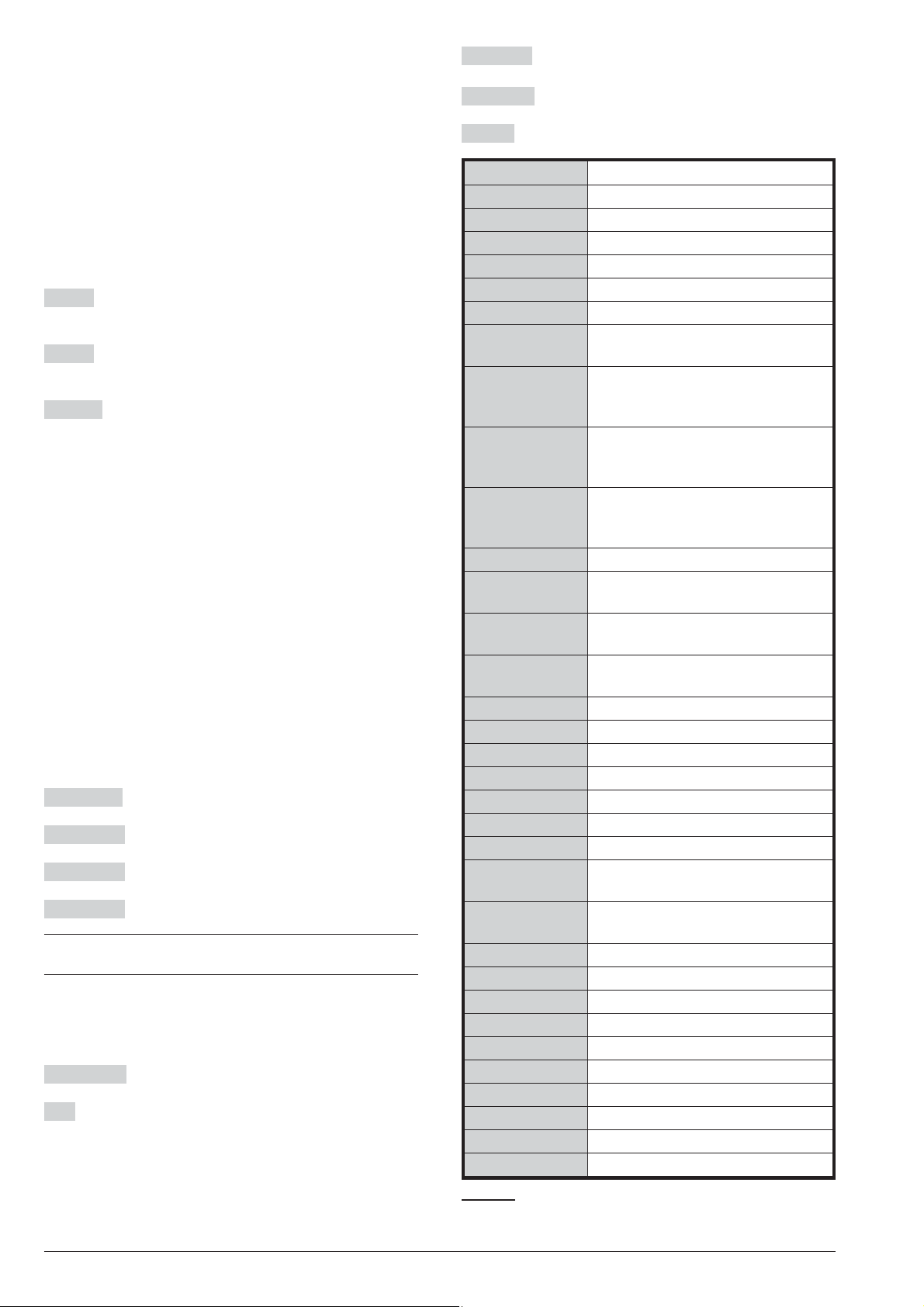
M-IN/OUT 6 Input/Output Expander
ABSOLUTA
M-Touch
ABSOLUTA
T-Black
ABSOLUTA
T-White
PREMIUM LCD
CLASSIKA LCD LCD Keypad
ECL2-UKR
(ECLIPSE2)
ECL2-C
(ECLIPSE2)
PROXI
SAT Proximity Key
SAT2 Proximity Key
PROXI-CARD Proximity Card
MINIPROXI Proximity Tag
PROXI-TAG/B Black Proximity Tag
PROXI-TAG/G Gray Proximity Tag
PROXI-TAG/W White Proximity Tag
AS100
BRM04/12
-
BXM12/30-B 3.6 A BPI Power Supply Station
BXM12/50-B 5.4 A BPI Power Supply Station
VRX32-868 868 MHz KEYBUS Receiver
VRX32-433 433 MHz KEYBUS Receiver
VRX32-433EN 433 MHz KEYBUS Receiver
VRP-433 433 MHz Repeater
MAXIASNC Big NC Tamper Switch
KST Thermal Probe
USB5M 5 m USB Cable
BOSS Console Software
Table 3 Compatible items.
Touchscreen Keypad
LCD keypad with Input/Output
Expander and Proximity Reader
on-board, black
LCD keypad with Input/Output
Expander and Proximity Reader
on-board, white
LCD Keypad with Input/Output
Expander and Proximity Reader on
board
Recessed Universal Reader
Module for Proximity Key
Cover for ECL2-UKR Universal
Reader Module
Indoor/Outdoor Proximity Reader
(IP34), for Proximity Key
Microphone + Loudspeaker
Station
4-Relay module for open-collector
outputs
ABSOLUTA INTRODUCTION 9
Page 10

Compatible items
Following a brief description of the items supported by
the ABSOLUTA, shown on the Table 3: refer to the
items instructions for further information.
ABS-IP This is an IP module that allows you to con
nect the ABSOLUTA control panel to a LAN through the
Ethernet interface or via WiFi, using the WiFi bridge
ABS-VAP11N supplied on request. This makes it possi
ble to:
program, monitor and check the control panel via the
Ø
BOSS application installed on a PC connected to the
same LAN as the control panel itself;
program, monitor and check the control panel via the
Ø
BOSS application installed on a PC connected to the
control panel via the Internet;
monitor the control panel using receivers Sur-Gard
Ø
SYSTEM I, II and III, via IP;
check thecontrol panel and report events notification
Ø
on iPhone and Android smartphones via the
ABSOLUTA app (push notifications);
report events via e-mail (push notifications).
Ø
ABS-GSM This is a GSM module that can be used by
the control panel as a backup dialler if the internal
PSTN dialler malfunctions or is tampered or can re
place it completely in areas accessed by mobile phone
services where a PSTN line is not available.
In that sense, the GSM Module is completely transparent to the control panel for the following functions:
Ø transmission of voice messages over a GSM chan-
nel;
Ø transmission of events with Contact ID and SIA pro-
tocol over a GSM channel;
Ø managing the control panel by telephone.
3
In order to comply with EN50131 Grade 3 standards, it is essential to use the ABS-IP IP module
for the notification of alarms: the built-in PSTN
communicator and GSM/GPRS ABS-GSM Module
can be used simultaneously.
The GSM Module also allows you to:
Ø
send SMS messages to a series of telephone num
bers in order to report events (alarms, tampers, trou
bles, etc.);
Ø
activate/deactivate the actions of the control panel
(outputs, voice messages, etc.) by sending SMS
messages to the number of the GSM Module;
Ø
activate actions just by recognizing the number that
is calling the GSM Module (at no cost);
Ø
check the control panel’s status by phone by sending
and receiving SMS messages;
Ø
Arm/Disarm the Partitions via SMS (ONLY Grade 2
Control Panels);
Ø
perform Teleservice (remote management and pro
gramming of the control panel) over the Internet on a
GPRS channel.
M-IN/OUT The M-IN/OUT is an Input/Output Expander
which allows the number of zones and outputs of the
Control Panel to be increased. It can be programmed to
function as: 6-zone Input Expander; Output Expander
with 6 Outputs; Input/Output Expander with 4 zones
and 2 Outputs; Input/Output Expander with 2 zones and
4 Outputs. In this manual the term Input Expander will
be used to refer to the M-IN/OUT programmed to func
tion as an Input Expander or Input/Output Expander;
-
-
-
-
-
-
the term Output Expander will be used to refer to the
M-IN/OUT programmed to function as an Output
Expander or Input/Output Expander.
An M-IN/OUT programmed as an Input/Output Ex
+
pander contributes both to the number of Input Ex
panders and to the number of Output Expanders
connected to the Control Panel.
In order to comply with EN50131-1 and EN50131-3
A
standards, the tamper and wall-tamper contacts of
the M-IN/OUT installed outside of the panel con
tainer, must be enabled: the M-IN/OUT’s TAMP
DIS jumper must be removed.
Access Control Devices The ABSOLUTA supports
ECLIPSE2 and PROXI Digital Key Readers, and
M-touch, T-Black, T-White, PREMIUM LCD and
CLASSIKA LCD Keypads.
The operating principles of the ECLIPSE2 and PROXI
Readers are the same, except:
Ø ECLIPSE2 Readers accept SAT Keys and
PROXI-CARD and are for indoor use (unless
mounted inside weatherproof boxes);
The ECLIPSE2 Key Reader is classified by the
A
EN50131-3 standard as Auxiliary Control Equipment (ACE), Type A.
Ø PROXI Readers have weather strips, and can be in-
stalled indoors or outdoors (IP34 Protection Class)
and accept SAT Keys and PROXI-cards.
Ø
ECLIPSE2 and PROXI Systems operate without contacts,
therefore, are highly resistant to oxidization and wear.
A
The PROXI Proximity Reader is classified by the
EN50131-3 standard as Auxiliary Control Equip
ment (ACE), Type A.
Ø
The operating principles of the T-Black, T-White,
PREMIUM and CLASSIKA Keypads are the same,
with a large display (2 lines of 16 characters); only
the T-Black, T-White and PREMIUM Keypads have
on-board proximity reader.
A
The T-Black, T-White and PREMIUM LCD
keypads, and the CLASSIKA LCD and M-Touch
keypads, are classified by the EN50131-3 stan
dard as Auxiliary Control Equipments (ACE), re
spectively Type B and Type A.
Ø
The M-Touch keypad has a large display allowing
the graphical display of information about the system
in colour. In addition, the display is touch sensitive so
interaction with this keypad is easy and intuitive.
-
-
-
-
-
-
-
10 Expandable Hybrid Control Panel
Page 11

Wireless Receivers This Control Panel supports one
VRX32-433, VRX32-433EN or VRX32-868 receiver
connected to the KEY BUS.
This receiver support up to 32 Wireless Detectors and
up to 16 Wireless Keys.
In order to comply with EN50131 Grade 3 stan
3
dards, Wireless Devices may NOT be used or, at
most, can be used in Grade 2 subsystems.
The VRX32-433 and VRX32-433EN receivers support
the following Detectors:
AMD20, AMD20NP - Wireless Pet-immune Infrared
Ø
Detector , PIR Detector
AMC30 - Wireless Magnetic Contact
Ø
ASD20 - Wireless Optical Smoke Detector
Ø
The VRX32-868 receiver support the following Detectors:
KMD20/ KMD20NP - Wireless Pet-immune Infrared
Ø
Detector , PIR Detector
KMC10/KMC20/KMC30 - Wireless Magnetic Contact
Ø
KSD20 - Wireless Optical Smoke Detector
Ø
The Control Panel can detect Alarm, Tamper, Low Bat
tery and Lost Wireless Detectors.
Power station The Power station has been especially
designed for Security system applications. The tamper
protected box (protected against opening and forced
removal) can house a backup battery for power supply
during black-out. This Control Panel supports
BXM12/30-B 3.6 A Power Station and BXM12/50-B
-
5.4 A Power station.
The BXM12/30-B power station is NOT certified
A
IMQ-SECURITY SYSTEMS and then NOT comply
to the EN50131-1, EN50131 and EN50131-3-6
standards.
BOSS The BOSS application (runs under Windows)
provides full Programming, Customer Database and
real-time Supervisory functions, and will allow you to
make the fullest use of all the system features.
Access Levels for panel management
Level 1 Access by any person: at this level you can ac
tivate only the Super-keys (the keys 1, 2 and 3 pressed
-
for at least 3 seconds). Eg. 1: Emergency, 2: Fire,
3: Alarm.
-
The following devices are NOT certified
A
IMQ-SECURITY SYSTEMS and then NOT comply
to EN50131-1 and EN50131-3: VRX32-433 and
VRX32-868 receivers; KMD20, KMD20NP,
KMC10, KMC20, KMC30, ASD20 and KSD20
wireless detectors.
When a Wireless Detector (assigned to a Zone) detects
Alarm conditions, the Control Panel will generate the respective Alarm on zone event, and other events which
depend on the programmed “Type” (refer to “Type” under “Zones”).
When a Wireless Detector (assigned to a Zone) detects
Tamper conditions, the Control Panel will generate the
respective Tamper on zone event, and other events
which depend on the programmed “Type” (refer to
“Type” under “Zones”).
When the battery of a Wireless Detector (assigned to a
Zone) is Low, the Control Panel will generate a Warn
ing low battery on wireless detector event. This
event will not identify the Wireless detector concerned.
However, the respective information will be recorded in
the log as follows:
Ø
TYPE - Low Battery
Ø
ID. EVENT - Label of the Wireless Zone no.
Level 2 Access by the Master, Limited and Normal
user, after entering a PIN (see “Quick guide for the LCD
Keypad menu” in the “APPENDIX” section).
Level 3 Access by the Installer and Super User
(Grade 3 Control Panels ONLY), after entering a PIN
and having been enabled by a Master User (see
“KEYPAD OPERATIONS” section and “Quick guide for
the LCD Keypad menu” in the “APPENDIX” section).
Level 4 Access by the manufacturer’s qualified personnel, after entering a PIN and have been enabled by
the installer (see “KEYPAD OPERATIONS” section and
“Quick guide for the LCD Keypad menu” in the
“APPENDIX” section).
-
When a Wireless Detector fails to transmit a supervi
sory signal within a certain time frame, the Control
Panel will generate a Lost wireless zone event.
-
ABSOLUTA INTRODUCTION 11
Page 12

Updates
The paragraphs below list the main updates for each
version of the Control Panel, together with the para
graphs in this manual and the USER MANUAL where
information on these can be found.
3.50 Grade 3
n
ABS16M50-G3 / ABS104M75-G3 Control Panels com
pliant with EN50131 Grade 3 standards:
INTRODUCTION > Control Panel versions > Grade
Ø
3 Control Panels.
Tripe End of Line Balance New type of supervision
to detect not only the alarm and tamper, but also faults
on grade 3 detectors (Grade 3 Control Panels ONLY):
INSTALLING > Connection of Grade 3 detectors;
Ø
PROGRAMMING FROM THE PC > Zones.
Ø
Super User New level 3 user type (Grade 3 Control
Panels ONLY) with permissions to delete the tamper
and fault memories (the Master User CANNOT carry
out these operations on Grade 3 Control Panels) and to
force certain blocking conditions on arming:
PROGRAMMING FROM THE PC > Codes and
Ø
Keys: User (PINs).
Ø USER MANUAL.
Support for Grade 3 Power Stations New events to
indicate low voltage on the power output and the auxiliary outputs of Grade 3 Power Stations (Grade 3 Control Panels ONLY):
Ø PROGRAMMING FROM THE PC > Configuration >
Power station.
n 3.50
ABS-IP New ABS-IP Module support.
Ø
INTRODUCTION > Features > Common Features
for all versions > IP;
Ø
INTRODUCTION > Compatible items > ABS-IP;
Ø
MOUNTING THE COMPONENTS > IP Module In
stallation;
Ø
PROGRAMMING FROM THE PC > IP.
Programming on LAN network and via Internet
Using the ABS-IP Module (optional) it is possible to
transmit/upload options from/onto BOSS installed on a
PC connected to the same LAN network as the Control
Panel and via Internet.
Ø
PROGRAMMING FROM THE PC > Down
loading/Uploading;
Ø
APPENDIX > Connection via IP.
Sur-Gard SYSTEM I / II / III Receiver Support
Transmission of events to the Sur-Gard SYSTEM I / II /
III via IP, with Contact ID and SIA reporting formats:
Ø
PROGRAMMING FROM THE PC > CENTRAL
STATION ACTIONS.
Smart SMS Support to create SMS messages to re
port events:
PROGRAMMING FROM THE PC > Smart Actions >
Ø
-
-
-
-
Smart SMS.
ABSOLUTA M-Touch 1.50 Support for the new
ABSOLUTA M-Touch touchscreen keypad:
USER MANUAL > OPERATIONS FROM TOUCH
Ø
KEYPAD.
3.00
n
Auto-reset Automatically reset of alarms stored during
the arming period:
PROGRAMMING FROM THE PC > System Options
Ø
> Reset alarm/tamper memory on arming (Master
code - keys);
USER MANUAL.
Ø
Storing SMS The GSM module is capable of storing
up to 32 SMS:
KEYPAD OPERATIONS > 3.3) View GSM Module
Ø
Status;
USER MANUAL.
Ø
Sur-Gard SYSTEM I / II / III Receiver Support
Transmission of events to the Sur-Gard SYSTEM I / II /
III via GPRS, with Contact ID and SIA reporting for
mats:
Ø PROGRAMMING FROM THE PC > Events and Ac-
tions > CENTRAL STATION ACTIONS;
Ø PROGRAMMING FROM THEPC > GSM > Cellular.
ABSOLUTA M-Touch Support for the new ABSOLUTA
M-Touch touchscreen keypad:
Ø USER MANUAL > OPERATIONS FROM TOUCH
KEYPAD.
The ABSOLUTA 3.00 does NOT support LED
+
(PREMIUM and CLASSIKA) keypads.
n
2.10
ABSOLUTA App iPhone and Android App for manag
ing the Control Panel from a smartphone:
Ø
PROGRAMMING FROM THE PC > Events and Ac
tions > Remote Controlled Events.
For more information, visit the BENTEL SECURITY site
(www.bentelsecurity.com
(https://itunes.apple.com
(https://play.google.com/store
In order to manage the Control Panel using the
ABSOLUTA APP, the user must know the IMEI of the
GSM Module installed on their Control Panel:
Ø
USER MANUAL > KEYPAD OPERATIONS > View >
GSM Module Status (3.3);
Ø
USER MANUAL > SMS OPERATIONS > GMS Mod
ule IMEI Request.
), the App Store
) or the Google Play Store
).
-
-
-
-
-
Events notification via e-mail and on ABSOLUTA app
Ø
PROGRAMMING FROM THE PC > Smart Actions >
Emails / APP Notifications;
PROGRAMMING FROM THE PC > Emails.
Arming/Disarming via SMS Option to Arm/Disarm
the Partitions via SMS:
Ø
USER MANUAL > SMS OPERATIONS > Arm/Dis
arm the Partitions.
12 Expandable Hybrid Control Panel
-
Page 13

Technical Specifications
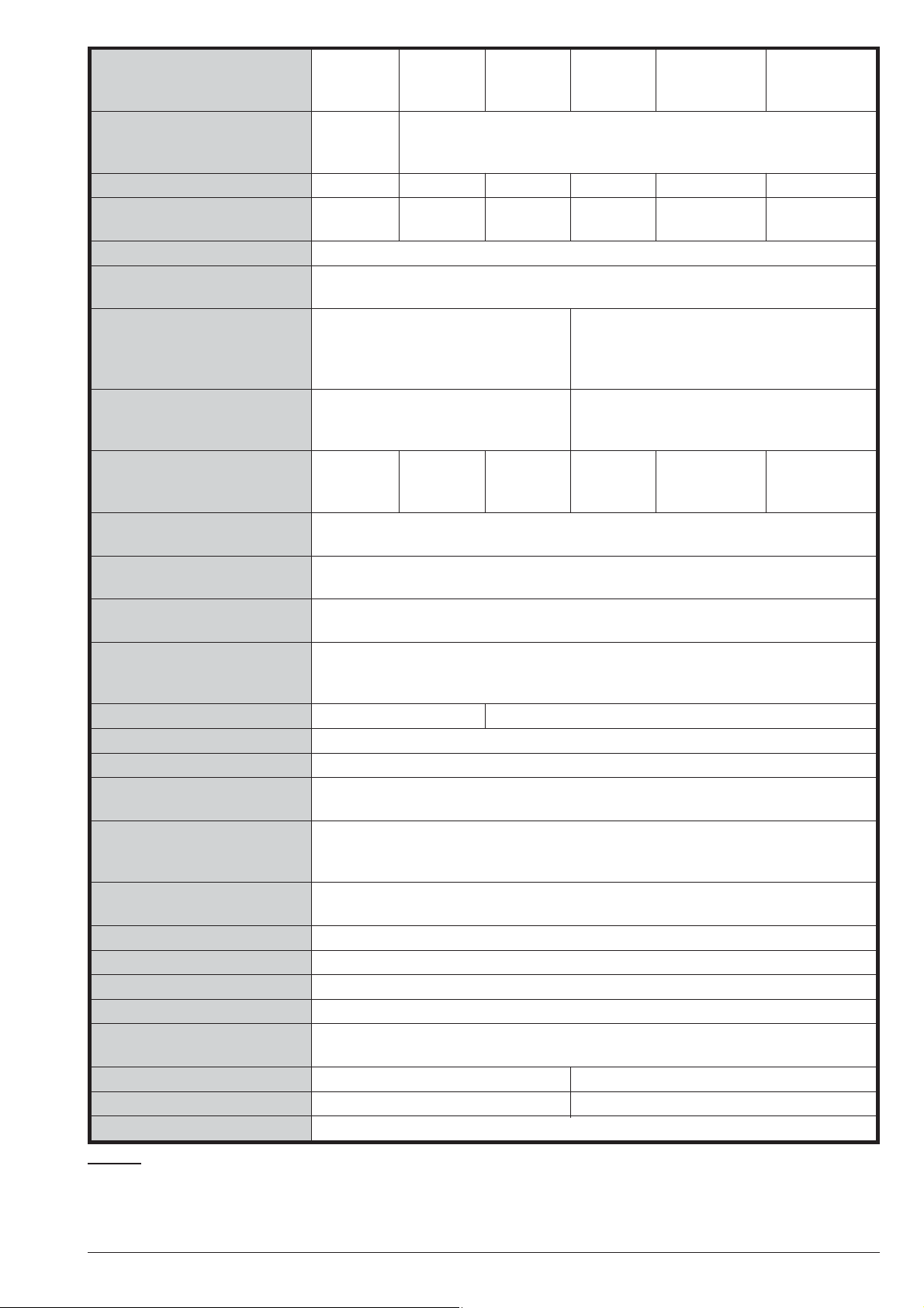
Table 4 inthe following page shows the technical Speci
fications of the ABSOLUTA series.
The below table shows the current draw (I (mA) col
umn) and size of the accessory components.
Components
ABSOLUTA Main Board 150 175x99x17
ABS-GSM Module 250 99x65,5x12
ABS-IP Module 300 99x65,5x12
ABSOLUTA M-Touch keypad 300 195x127.9x20.3
ABSOLUTA T-Line Keypad
with proximity reader enabled
with proximity reader disabled
PREMIUM Keypadwith
proximity reader enabled
with proximity reader disabled
CLASSIKA Keypad 50 144.5x116x27.5
ECLIPSE2 Key Reader 30 —
PROXI Key Reader 30 78x108x22
M-IN/OUT Programmable
Input/Output Expander
BRM04/12 4 Relay Module 120
BXM12/30-B Power Station 10 240x348x97
BXM12/50-B Power Station 10 240x348x97
I
(mA)
6050134x114x28,5
6050134x114x28.5
20
Size
(WxHxD mm)
108x101x34
-
-
ABSOLUTA INTRODUCTION 13
Page 14
Versions
Voltage 230 V~
Max. Current Draw 0.42 A 0.75 A 1.1 A 0.75 A 1.1 A 1.7 A
Power Supply Battery-Charger
(Type A - EN50131-6)
Insulation Class I
Maximum ripple voltage on
the outputs
Battery
(Brand and Type)
Max. Current available for
peripherals and loads (Aux
Output)
Max. Battery Charge Current 0.92 A
Maximum Battery Recharge
Time to 80%
Minimum Duration of
Alternative Power Supply
Low Battery Fault
Generated
Generation of Low Output
Voltage Fault, without
backup batteries
Overvoltage Protection N/A 16.7 V
Deep Discharge Protection 9.6 V
Digital Key Combinations 4,294,967,296
Alarm Transmission System ATS2 (with built-in PSTN communicator and/or ABS-GSM module)
Delay for alarm messages
generation and
transmission
Delay for fault detection and
visualization
IP Protection Grade IP20
Security Grading 2(3forABS16M50-G3 and ABS104M75-G3 Control Panels)
Environmental Class II
Operating Temperature -10 to +40 °C
Operating Humidity (not
condensed)
Dimensions (WxHxD) 319x352x92 mm (without antenna) 310x403x103 mm (without antenna)
Weight 2.09 Kg (without battery) 4.89 Kg (without battery)
Complies with EN60950-1/A1:2010; EN50130-4:2011; EN50131; EN50136
ABS16P15
ABS42P15
-15/+10%
50/60 Hz
13.8 V_
±2% 1.5 A
similar Case Flame Class UL94-V2 or
(7 Ah
battery)
ABS16P35
ABS42P35
13.8 V_
±1% 2.6 A
Lead Acid 12 V / 7 Ah
YUASA NP 7-12 FR or
higher
430 mA
(7 Ah battery)
2.02 A
(7 Ah
battery)
ABS42P50
ABS104P50
13.8 V_
±1% 3.6 A
battery)
ATS5 (with ABS-IP module)
110-230 V~ -15/+10% 60-50 Hz
310 mV (2.25%)
3.02 A
(7 Ah
ABS16M35
13.8 V_
±1% 2.6 A
similar Case Flame Class UL94-V2 or higher
1.2 A
(17 Ah
battery)
24 h
12 h
11.4 V
11.2 V
2s
2s
0 to 93% RH
ABS16M50-G3
ABS42M50
ABS104M50
13.8 V_ ±1%
3.6 A
Lead Acid 12 V / 17 Ah
YUASA NP 17-12 FR or
1,250 mA
(17 Ah battery)
2.2 A
(17 Ah battery)
ABS42M75
ABS104M75
ABS104M75-G3
13.8 V_ ±1%
*
(17 Ah battery)
5.4 A
4.0 A
Table 4 Technical Specifications: *) 400 mA for Grade 3 Control Panels connected to a Central Station; 550 mA in or
der to comply with the T014 standard, for ABS104M50, ABS104M75-G3, ABS42M50, ABS16M35, and
ABS16M50-G3 control panels, that must be connected to a Central Station.
14 Expandable Hybrid Control Panel
-
Page 15
IDENTIFICATION OF PARTS
1 2345 67 8 9 1 5 7 10 1
11
12
13
141516171819
22
21
20
11
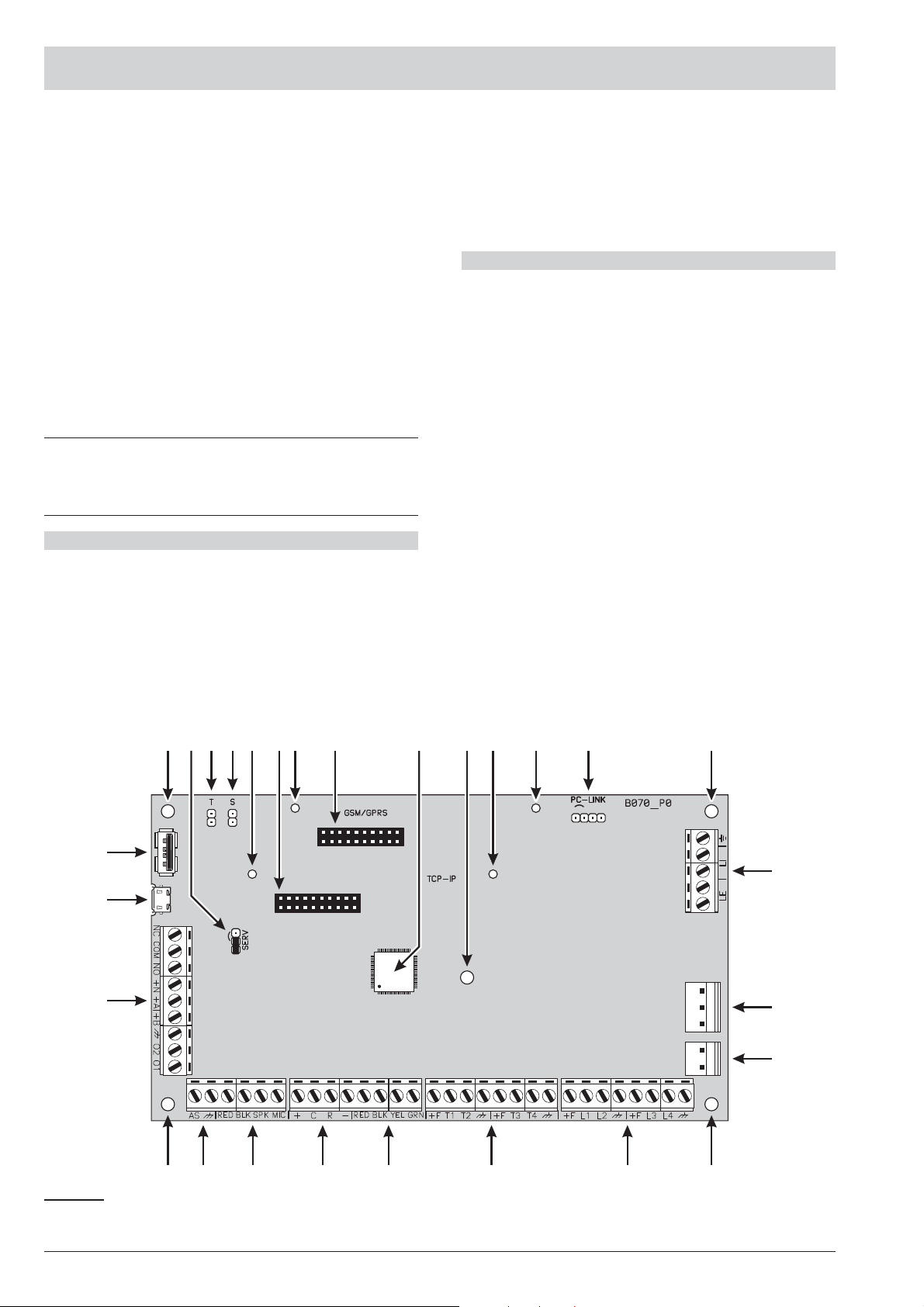
Please read this section carefully to get an overall view
of the main components of the Control Panel.
The numbers in boldface (used in this text) refer to the
descriptions in the tables and figures in this section.
The components are generally numbered in clockwise
order. The outlined numbers refer to the common hard
ware components of the devices and are described
once only — when first encountered.
Figures 2 and 3 show the maximum configuration
+
of the respective Control Panels, therefore, some
of the components may not be present on your
Control Panel.
N. DESCRIPTION
1 Main board fixing holes
2 Jumper to disable the activation of the Outputs
and Telephone Actions (Voice Calls, Voice Messages on AS100, Digital Calls and SMS):
//o = Actions Enabled (factory settings);
o// = Actions Disabled.
3 Opening tamper switch connector
4 Wall tamper switch connector
N. DESCRIPTION
5 Holes to fit the IP Module
6 Connector for the IP Module
7 Holes to fit the GSM Module
8 Connector for the GSM Module
9 Microprocessor
-
10 RS232 Serial Port
11 Terminals for telephone line connection
12 Switching power Supply connector
13 Connector for backup Battery
14 Input terminals for detector connection
15 Programmable terminals as inputs or outputs
16 KEY BUS terminals for Wireless Receiver con
nection
17 BPI BUS terminals for BPI peripheral connection
18 Terminals for Audio Station connection
19 Terminals for Tamper Line connection
20 Terminals for output device connection (Sirens,
etc.)
21 USB Micro AB serial port for downloading/up-
loading on PC
22 USB Serial Port for downloading/uploading on
USB pen and PC.
-
Figure 1 ABSOLUTA Main Board parts.
ABSOLUTA IDENTIFICATION OF PARTS 15
Page 16
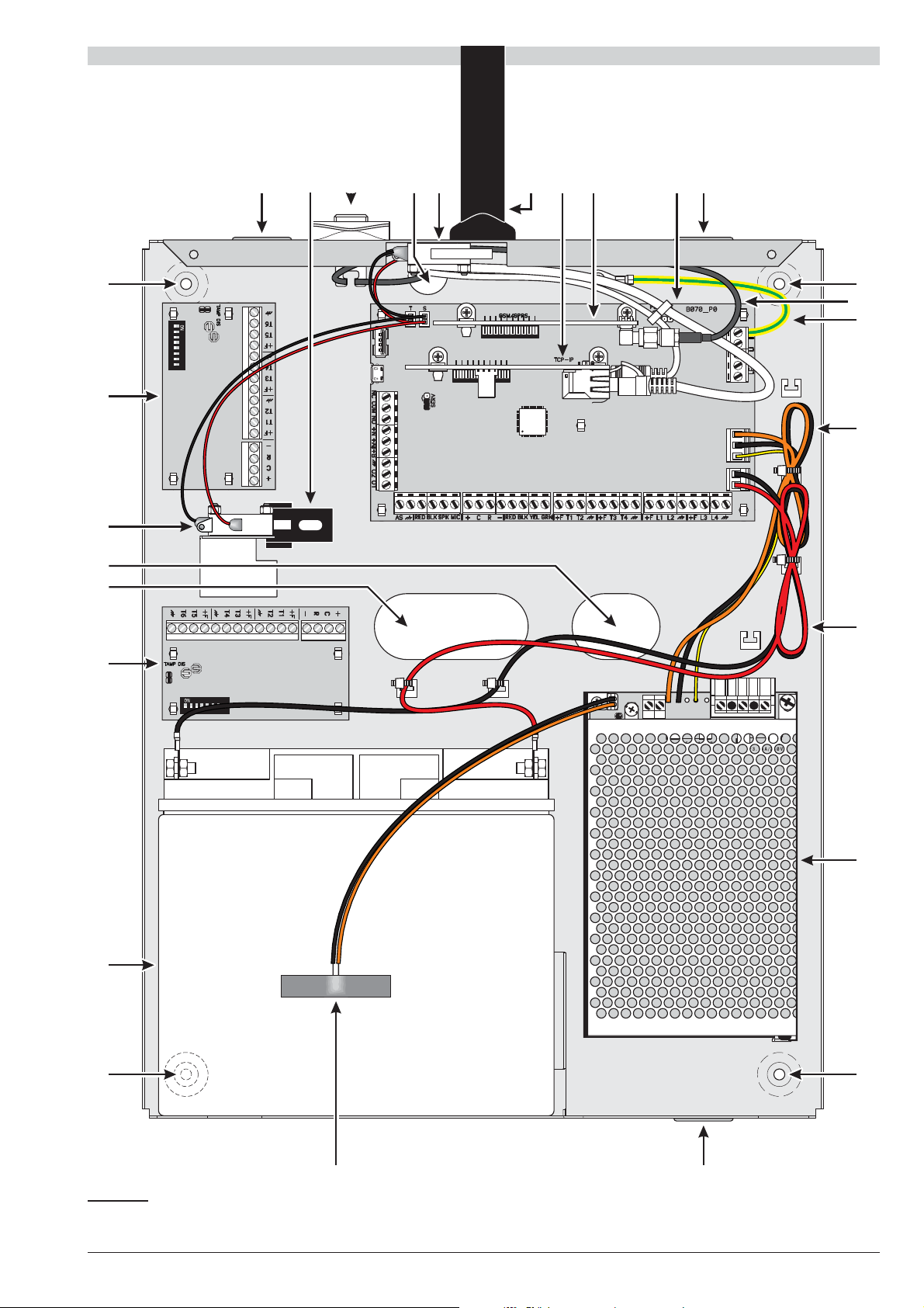
N. DESCRIPTION
AC/NFG+VGND
B+LB–
GND
+V
AC/L
F3.15A/25ØV
F6.3A/25ØV
12345678
12345678
27
25c
23 24 25 24b 2625a 23
28
29
30
31
27
23
27
33
34
35
36
37
38
27
32
25b24a 43
Frontplate screws (2)
23 Surface Cable conduit entry
24 Wall tamper switch bracket
24a ABS-VAP11N Bridge WiFi
24b ABS-IP IP module
N. DESCRIPTION
25 Tamper switch
25a BGSM-100CA, Antenna with a magnetic base
and 25 cm cable
25b ABS-GSM, GSM Module
25c BGSM-100CA antenna cable
Figure 2 Parts of the ABSOLUTA in the Metal Box.
16 Expandable Hybrid Control Panel
Page 17
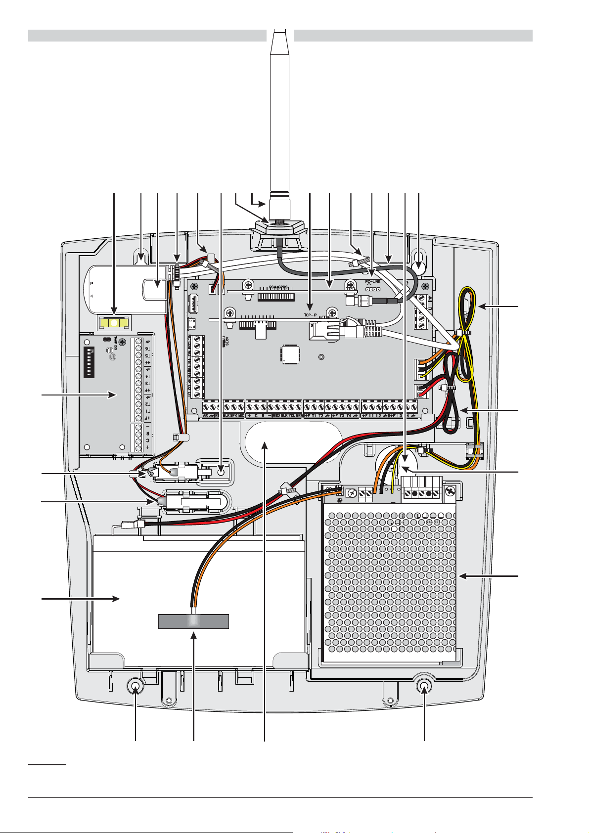
N. DESCRIPTION
AC/NFG+VGND
B+
L
B–
GND
+V
AC/L
F 2A/25ØV
F6.3A/25ØV
12345678
27 61 24 39 26 36 27
27353227
29
30
40
31
38
37
25
37
38a
25b24b 39b39a61 6224a
26 Main Board (see Fig. 1)
27 Backplate anchor screw locations
28 Earth connection
29 Stranded wires: connect the Switching Power
Supply to the Main board
30 Cable for battery connection
31 Switching Power Supply
32 Thermal probe (accessory item)
33 Battery location
34 Location for second Input/Output Expander
N. DESCRIPTION
35 Main cable entry
36 Auxiliary cable entry
37 Wall tamper switch
38 Location for first Input/Output Expander
38a Bubble level
39 Hole for the antenna
39a ABS-AK GSM Antenna for plastic box
39b Connecting cable for the ABS-AK antenna
40 Cap to close the hole 39
Figure 3 Parts of the ABSOLUTA in the Plastic Box.
ABSOLUTA IDENTIFICATION OF PARTS 17
Page 18
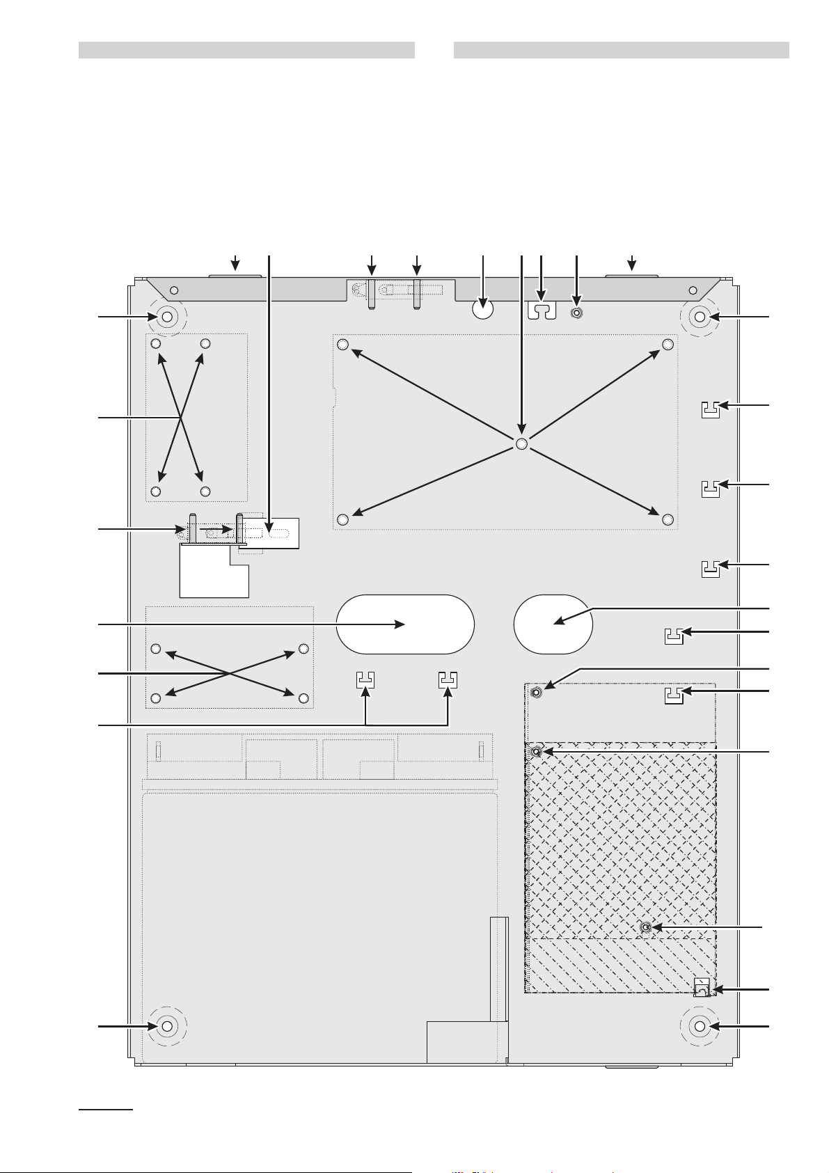
N. DESCRIPTION
BAW75T12
BAW35T12
BAW50T12
27
23323
2727
35
36
57
27
41 454342 44 4642
47
48
49
50
52
53
54
58
56
51
55
53a
41 Aperture for wall-tamper bracket
42 Two pivots for opening-tamper switch fixing
43 Hole for the GSM antenna wire
44 Five holes for Main Board fixing
45 Anchor for the GSM antenna wire
46 Hole for earth cable fixing
47 Anchor for the telephone line wires
48 Anchor for the power supply wires
49 Anchor for the battery wires on the Main Board side
50 Anchor for the Main wires on the BAW75T12
N. DESCRIPTION
51 Hole for BAW75T12 fixing
52 Anchor for the Main wires on BAW35T12 and
BAW50T12
53 Hole for BAW35T12 and BAW50T12 fixing
53a Hole for BAW35T12 fixing
54 Arrester for the Power Supplier
55 Anchor for the battery wires on the battery side
56 Four holes to fix the second M-IN/OUT
57 Two pivots for wall-tamper switch fixing
58 Four holes to fix the first M-IN/OUT
Figure 4 Mounting the Metal Box.
Page 19

MOUNTING THE COMPONENTS
Mounting the Metal Box
Please read the following instructions, to get an overall
view of the steps involved in the control panel mounting
with the ABS-M Metal Box: refer to Figure 4 and Figure
2 on page 16.
Installing ABSOLUTA Main Board
1. Insert the five reverse locking supports into the
holes 44 on the backplate.
2. Place the Main Board on the supports, then press it
down until blocks in its position.
3. Secure the Earth wire (Yellow-Green) eyelet to the
hole 46 on the backplate, by means the screw
M3x8 and washer.
4. Connect the other end of the Earth wire (Yellow-Green) 28 to terminal - on the ABSOLUTA
Main Board.
The Main Board must be earthed in order to pro-
!
tect it from electrical surges from the Telephone
Line, and comply with Safety Regulations.
Installing the Power Supply You can install the
Switching Power Supply BAW35T12, BAW50T12 or
BAW75T12 into the Metal Box, as shown in Figure 2 on
page 16 (part nr. 31).
5. Cut the battery cables on the power supply.
The backup battery must be connected to the con-
+
nector 13 on the Main Board. It can NOT be connected directly to power supply.
6. BAW50T12/BAW75T12: slide the Power Supply
tab under the hook 54.
BAW35T12: screw a M3X8 screw on the hole 53a,
loosely, then slide the Power Supply tab in the
screw and tighten it.
7. Secure the BAW75T12 to the hole 51, the
BAW50T12 and the BAW35T12 to the hole 53,by
means the washer and screw (M3x8).
Installing the Tamper Switch You can install the
MAXIASNC switch (accessory item required to comply with
the EN50131-1 and EN50131-3 standards) to detectthe box
opening, as shown in Figure 2 on page 16 (part nr. 25).
10. Secure the MAXIASNC switch to its location using
the two hexagonal nuts.
11. Connect the wire to the connector 3 (T) on the Main
Board.
Installing the Wall-Tamper Switch You can install the
MAXIASNC switch (accessory item required to comply with
the EN50131-1 and EN50131-3 standards) to detectthe box
removal, as shown in Figure 2 on page 16 (part nr. 37).
12. Place the Wall-Tamper Bracket 24 into the opening
41 on the backplate.
13. Secure the MAXIASNC switch to its location using
the two hexagonal nuts.
14. Connect the wire to the connector 4 (S) on the Main
Board.
Installing the Input/Output Expander Module You
can install up to two Input/Output Expander Modules
M-IN/OUT into the Metal Box, as shown in Figure 2 on
page 16 (parts nr. 34 and 38).
15. Insert four reverse locking supports into the holes 58
and/or into the holes 56 on the backplate, depending
on if you are installing one and/or two Modules.
16. Place the Module PCB on the supports, then press
it down until blocks in its position.
17. Disable the tamper and wall-tamper contacts by inserting (closing) the jumper on the Input/Output Expander Module (TAMP DIS).
Marking Label Once you have assembled the components, specify on the data label (which is located on the
outer right side of the box) the type of Control Panel that
you have constructed.
18. Using an indelible pen, tick the relevant box on the
Marking Label according to the following table.
8. Insert the Power Supply plug into the connector 12
on the Main Board.
9. Secure the exceeding wires to the anchor 48 on the
backplate.
ABS-M Power Supplies
Main Boards BAW35T12 BAW50T12 BAW75T12
ABS16 ABS16M35 N/A N/A
ABS42 N/A ABS42M50 ABS42M75
ABS104 N/A ABS104M50 ABS104M75
ABSOLUTA MOUNTING THE COMPONENTS 19
Page 20

Mounting the Plastic Box
Please read the following instructions, to get an overall
view of the steps involved in the control panel mounting
with the ABS-P Plastic Box: refer to Figure 5 and Fig
ure 3 on page 17.
To comply with the EN50131-1 and EN50131-3
A
standards, detach the cap 40 from the bottom, and
insert it into the hole 39.
Installing ABSOLUTA Main Board
10. Connect one end of the Earth wire (Yellow-Green)
to terminal - on the ABSOLUTA Main Board, and
the other to terminal Q on the BAQ35T12 Switching
Power Supply.
-
The Mother Main must be earthed in order to pro
!
tect it from electrical surges from the Telephone
Line, and comply with Safety Regulations.
11. Insert the Switching Power Supply plug into the
connector 12 on the ABSOLUTA Main Board.
-
1. Slide the Main Board under the 2 tabs 67.
2. Secure the Main Board to the holes 60 on the
backplate using the two self tapping screws .
Installing BAQ15T12 Power Supply Read the fol
lowing steps to install the BAQ15T12 Power Supply,
otherwise skip to “Installing BAW35T12 and
BAW50T12 Power Supply”.
3. Cut the battery cables on the power supply.
The backup battery must be connected to the con
+
nector 13 on the Main Board. It can NOT be con
nected directly to power supply.
4. Using the 2 self tapping screws (3 x 8), secure the
BAQ15T12 to the holes 71 on the backplate..
5. Connect one end of the Earth wire (Yellow-Green)
28 to the Earth terminal - on the ABSOLUTA
Mainr Board, and the other to terminal Q on the
BAQ15T12 Switching Power Supply.
The Main Board must be earthed in order to pro-
!
tect it from electrical surges from the Telephone
Line, and to comply with Safety Regulations.
Installing the Tamper Switch You can install the
MAXIASNC switch (accessory item required to comply
with the EN50131-1 and EN50131-3 standards) to de
tect the box opening, as shown in Figure 3 on page 17
(part nr. 25).
-
-
-
12. Insert the MAXIASNC switch into its location.
13. Connect the wire to the connector 3 (T) on the Main
Board.
Installing the Wall-Tamper Switch You can install
the MAXIASNC switch (accessory item required to
comply with the EN50131-1 and EN50131-3 standards)
to detect the box removal, as shown in Figure 3 on
page 17 (part nr. 37).
14. Insert the MAXIASNC switch into its location.
15. Connect the wire to connector 4 (S) on the Main
Board.
Installing the Input/Output Expander Module You
can install one Input/Output Expander Module
M-IN/OUT into the Plastic Box, as shown in Figure 3 on
page 17 (part nr. 38).
16. Slide the Module PCB under the tab 78.
-
6. Plug the Switching Power Supply into the connec
tor 12 on the ABSOLUTA Main Board.
Installing BAW35T12 and BAW50T12 Power Supply
Read the following steps to install the BAW35T12 or
BAW50T12 Power Supply or skip to “Installing the Tam
per Switch”.
7. Cut the battery cables on the power supply.
The backup battery must be connected to the con
+
nector 13 on the Main Board. It can NOT be con
nected directly to power supply.
8. BAW50T12: slide the Power Supply tab under the
hook 72.
BAW35T12: screw a self tapping screw 3 x 8 mm
on the hole 71, loosely, then slide the Power Supply
tab in the screw and tighten it.
9. Using the self tapping screw (3 x 8), secure the
power supply to the hole 75.
-
-
-
-
17. Secure thePCB to the hole 79 on the backplate, us
ing the self tapping screw.
18. Disable the tamper and wall-tamper contacts by in
serting (closing) the jumper on the Input/Output Ex
pander Module (TAMP DIS).
Marking Label Once you have assembled the compo
nents, specify on the data label (which is located on the
battery holder shelf) the type of Control Panel that you
have constructed.
19. Using an indelible pen, tick the relevant box on the
Marking Label according to the following table.
ABS-P Power Supplies
Main Boards BAQ15T12 BAW35T12 BAW50T12
ABS16 ABS16P15 ABS16P35 N/A
ABS42 ABS42P15 ABS42P35 ABS42P50
ABS104 N/A N/A ABS104P50
-
-
-
-
20 Expandable Hybrid Control Panel
Page 21
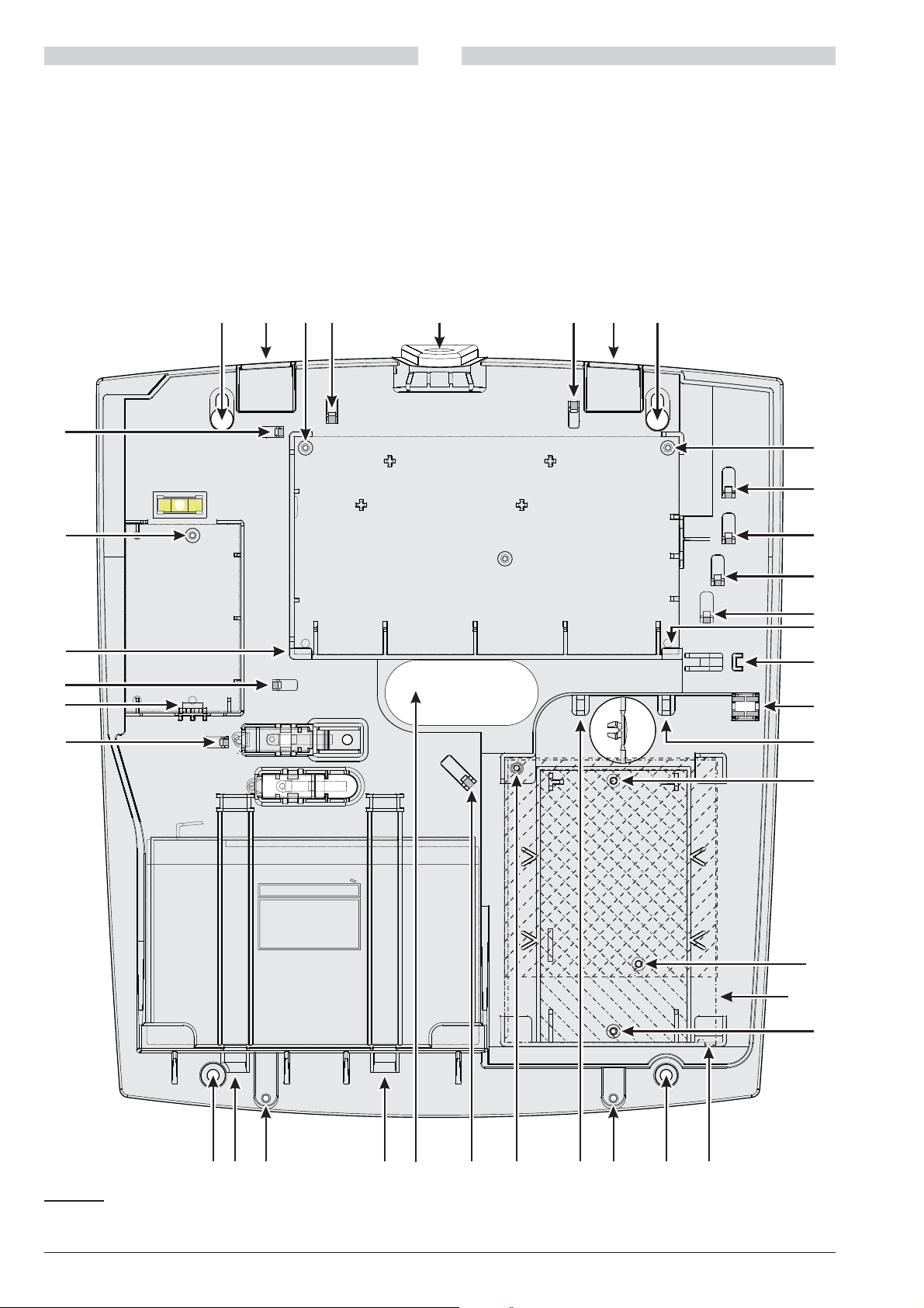
BAQ15T12
BAW35T12
27 39 27
273527
59 60 61 62 59
60
63
64
65
66
67
68
69
70
71
71
7273747576777377
61
78
61
67
79
61
71a
BAW
50T12
N. DESCRIPTION
59 Two hooks to hang the Cover
60 Two holes for Main Board fixing
61 Four anchors to fix the tamper switch wires
62 Future use
63 Anchor for earth wire fixing
64 Anchor for the telephone line wires
65 Anchor for the power supply wires
66 Anchor for the battery wires on the Main Board side
67 Two tabs to retain the Main Board
68 Future use
69 Future use
N. DESCRIPTION
70 Anchor for the Main wires on the BAW35T12
and BAW50T12
71 Two holes for BAQ15T12 fixing
71a Hole for BAW35T12 fixing
72 Arrester for the BAQ35T12
73 Two holes to secure the Cover
74 Anchor for the Main wires on the BAQ15T12
75 Hole for BAW35T12 and BAW50T12 fixing
76 Anchor for the battery wires on the battery side
77 Two guides to anchor the battery
78 Tab to retain the M-IN/OUT
79 Hole for M-IN/OUT fixing
Figure 5 Mounting the Plastic Box.
ABSOLUTA MOUNTING THE COMPONENTS 21
Page 22
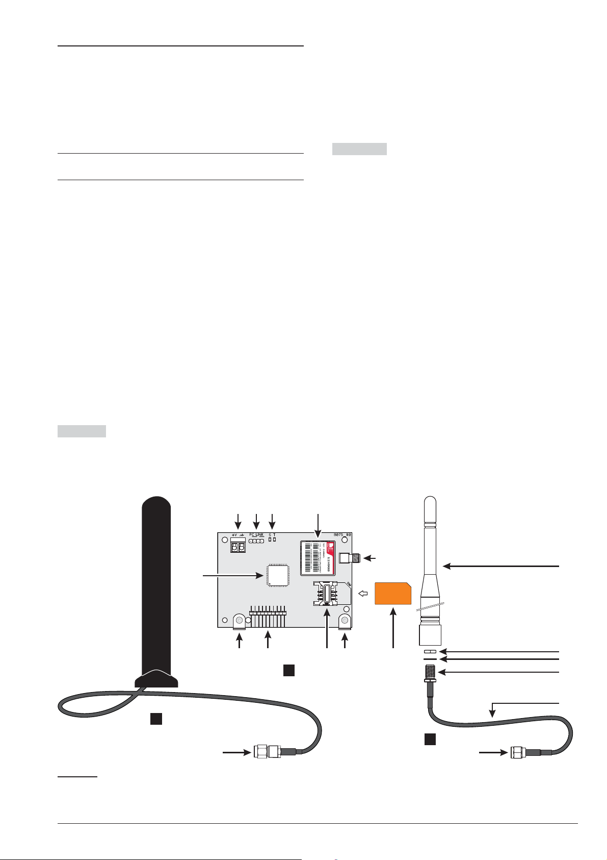
Installing the GSM Module
89
101
94
90 91 92
102
93
103 102101
95
96
97
98
9999
100
a
b
c
Before installing the GSM Module, make sure
!
that the control panel is not connected to the
power supply.
Before inserting or removing the SIM card,
!
make sure that the GSM Module is not con
nected to the power supply.
Disable the PIN and call forwarding on the SIM
+
card before inserting it in the GSM Module.
The ABS-GSM Module can be installed in the ABS-M
metal box and the ABS-P plastic box as shown in Figure
2 on page 16 and in Figure 3 on page 17 (part n. 25b)
respectively and described below (see Figure 6).
1. Insert the SIM card in SIM holder 102 of the Mod
ule.
2. Insert the GSM Module on connector 8
(GSM/GPRS), while being careful to make the
holes on corner guards 101 coincide with the holes
7 on the Motherboard.
Inserting the GSM Module incorrectly may lead
!
to serious damage.
3. Attach the GSM Module to the holes 7 using the
screws provided.
Metal Box Installation in the ABS-M metal box requires antenna BGSM-100CA (b).
4. Place antenna BGSM-100CA on the top of the
metal box as far away from the wall as possible.
5. Thread the antenna’s wire through hole 43 on the
bottom of the control panel and then connect it to
connector 93 of the GSM Module.
-
-
6. Fix the antenna wire to anchor 45.
Plastic Box Installation inside plastic box ABS-P re
quires the ABS-AK antenna (c).
7. Remove bolt 95 and washer 96 from connector 97
of wire 98 provided with the ABS-AK antenna.
8. Insert connector 97 in hole 39 of the ABS-P box.
9. Insert washer 96 and screw in bolt 95 until connec
tor 97 is blocked.
10. Screw antenna 94 onto connector 97.
11. Screw connector 99 onto the Module’s connec
tor 93.
Check that the GSM signal is strong enough at the loca
tion chosen for the control panel’s installation (see Sta
tus page); if it is NOT strong enough, try to move the
antenna on the metal box or the control panel or try with
the ANT-EU external antenna.
Program the options for the GSM Module: GSM and
SMS Message option groups.
-
-
-
-
-
Figure 6 Parts of the ABS-GSM Module (a), of the BGSM-100CA antenna for metal box (b), and of the ABS-AK an
tenna for plastic box (c).
22 Expandable Hybrid Control Panel
-
Page 23

Installing the IP Module
110
104
113
112 111 110
109
107
114
115
a
b
105 106
108
Before installing the IP module, make sure the con
!
trol panel is NOT connected to the power supply.
DO NOT use the USB power supply adaptor
!
provided with the ABS-VAP11N to connect the
-
115 connector to the USB port on the Control
Panel (22).
The IP module can be installed in the metal ABS-M box
and in the ABS-P plastic one, as shown respectively in
Figures 2 on page 16 and in Figure 3 on page 17 (part
no. 24b) and described below (see Figure 1 on page 15
and Figure 7).
1. Insert the IP module to the connector 6 (TCP-IP),
making sure that the holes in the angular brackets
110 on the Module coincide with the holes 5 on the
motherboard.
The IP Module may be severely damaged if not
!
properly inserted.
2. Secure the IP module to the holes 5, using the
screws provided.
3. Connect connector 106 to the LAN via an Ethernet
cable, or refer to the next paragraph if you plan to
install the ABS-VAP11N WiFi bridge (not supplied).
Use a category 5 (or better) shielded Ethernet ca
+
ble (STP or FTP)
4. Program the options for the IP module: see
“PROGRAMMING FROM THE PC > IP”.
Installation of the ABS-VAP11N in the Metal Container To
install the ABS-VAP11N in the ABS-M metal box, proceed as described below (Figure 2 on page 16).
3. Fix the ABS-VAP11N to top of the control panel
container using the double-sided adhesive, in the
position shown in Figure 2 on page 16.
DO NOT place the ABS-VAP11N inside the metal
+
container of the control panel.
4. Configure the ABS-VAP11N as indicated in the in
structions, which can be downloaded from the fol
lowing page:
http://vonets.com/ProductViews.asp?D_ID=24
Installation of the ABS-VAP11N in a Plastic Container
To install the ABS-VAP11N in the ABS-P plastic con
tainer, proceed as described below (Figure 3 on
page 17).
1. Connect connectors 114 and 115 of the
ABS-VAP11N to connectors 106 and 109 of the IP
-
Module respectively.
DO NOT use the USB power supply adaptor
!
provided with the ABS-VAP11N to connect the
115 connector to the USB port on the Control
Panel (22).
2. Run the ABS-VAP11N cables to the hooks 61 and
62, and fix using cable ties.
-
-
-
1. Pass connector 114 and connector 115 of
ABS-VAP11N through hole 43 in the bottom of the
control panel.
2. Connect connectors 114 and 115 of the
ABS-VAP11N connectors 106 and 109 of the IP
Module respectively.
Figure 7 Parts of the ABS-IP Module (a) and the ABS-VAP11N WiFi Bridge (b).
3. Configure the ABS-VAP11N as indicated in the in-
structions, which can be downloaded from the fol
lowing page:
http://vonets.com/ProductViews.asp?D_ID=24
-
ABSOLUTA MOUNTING THE COMPONENTS 23
Page 24

Page 25

INSTALLING
Mounting the Control Panel
Please read this section carefully to get an overall view
of the steps involved in installing the ABSOLUTA Con
trol Panel.
The ABSOLUTA Control Panel should be located in a
safe, dry place that is far from sources of interference.
Once you have selected a suitable place, create a lay
out of all the system peripherals (Keypads, Readers,
Detectors, etc.) and ensure that you will be able to con
nect the Main power, peripherals, and if necessary, the
telephone line to the ABSOLUTA without difficulty.
Allow at least 5 cm of free space around the Main Unit
for air flow.
The Main Unit must be at least 2 metres from re-
!
lay systems.
Work carefully through the following steps (see figures
on pages 16 and 17).
1. Remove the screws and frontplate.
2. Install the accessory and plug-in modules following
the instruction in the “MOUNTING THE
COMPONENTS” section.
It is recommended to use wall anchors of at
!
least 6 mm diameter to mount the Control Panel.
3. Drill the holes for the backplate and wall-tamper
bracket anchor screws (27 and 24 respectively).
4. Pull the connection wires through the wire entry 35
and 36 then attach the backplate and wall-tamper
bracket to the wall.
Mounting the BPI Peripherals
Read the instructions provided to mount theBPI peripherals.
-
-
-
Keypads Keypads should be located in places where
full control of the system is required.
Readers Readers can be located in places where lim
ited control of the system is required (Arming, A and B
Mode Arming, Disarming operations).
Input/Output Expander Fix the M-IN/OUT Input/Out
put Expander as close as possible to the devices to
which it is to be connected.
Power Stations Locate the Power Supply Station as
near as possible to the devices it must supply, this will re
duce the voltagedrop on the connections toa minimum.
-
-
-
Terminals
This paragraph describes the Control Panel terminals.
The layout of Terminal Description table is as follows:
Ø the Ter. column shows the terminal identifier;
Ø the DESCRIPTION column provides a brief descrip-
tion of each terminal;
Ø the v(V) column shows the terminal voltage (the hy-
phen “–” indicates that the voltage cannot be specified for the terminal concerned);
Ø
the i(A) column shows the maximum current (in Am
peres) that can circulate on the terminal (the hyphen
“–” indicates that the current cannot be specified for
the terminal concerned);
Ø
the numbers inbrackets refer to the following notes.
(1) The total current draw of terminals [+A], [+N], [+B],
[+F], [+] and [RED] must not exceed the allowed limit for
the control panel in object (refer to Max. Current avail
able for peripherals and loads (Aux Output) in Ta
ble 4 on page 14).
-
-
-
DO NOT over tighten the screws as this may dam
+
age the wall-tamper bracket.
5. Complete the connections — DO NOT connect the
MAINS until all other wiring has been completed.
6. Connect the Mains Power (refer to “Connecting the
Mains Power”).
7. Program the system (refer to the “PROGRAMMING
FROM THE PC” and the “KEYPAD OPERATIONS”
sections for instructions).
-
(2) The voltage on the [+A], [+N], [+B], [+F] and [+] ter
minals, under normal operating conditions, can change
from 13.8 to 13.6 V. The output voltage below which a
Fault event is generated is 12.2 V.
(3) The voltage on the [RED] terminals, under normal
operating conditions, can change from 13.8 to 13.4 V.
(4) The max. voltageadmitted on the changeover switch
contacts is 15 V @ 2 A (Max. switching power 30 W).
(5) In order to comply with the T 014 standards, these
terminals CANNOT be used to connect a wireless re
ceiver.
ABSOLUTA INSTALLING 25
-
-
Page 26
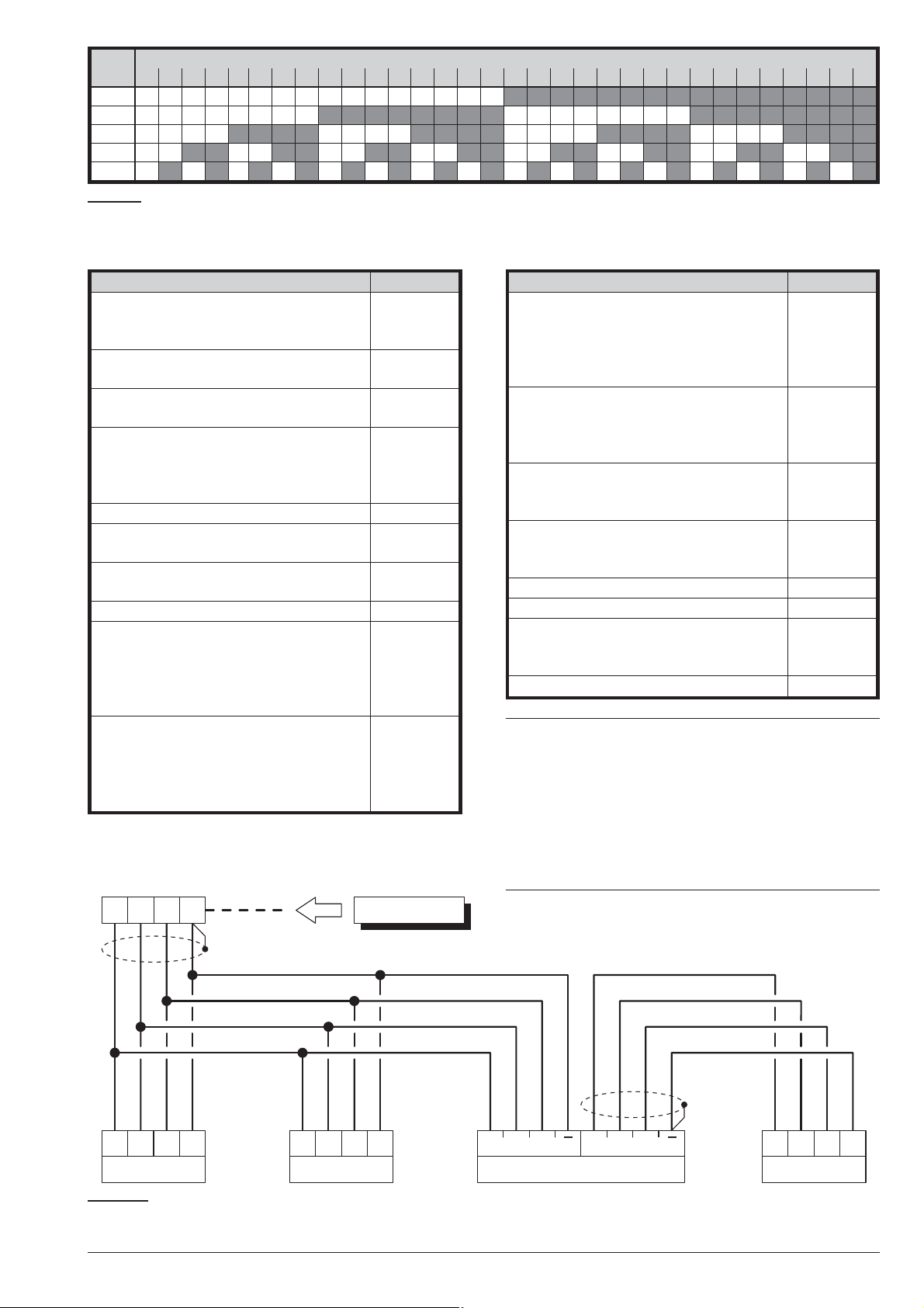
+
C
R–
BPI device
C
R+–
BPI device
RC+–
Panel
Power station
RC
+
RC
+
BPI IN BPI OUT
BPI device
RC+–
N. ADDRESS
1234567891011121314151617181920212223242526272829303132
1
(1) 2
(2) 3
(3) 4
(4) 5
Table 5 Assignment of addresses: column N. shows the microswitch numbers (refer to the number in parentheses for
the power feeding supply address settings); a white square indicates that the respective microswitch must be OFF
and a gray square indicates that the respective microswitch must be ON.
Ter. DESCRIPTION v(V) i(A)
NC
Programmable Output n. 1
COM
(changeover switch contacts)
(4) 2
NO
+N Programmable Output n. 1 (intrin
sic security), protected by fuse
+A Programmable Output n. 1 (posi
tive), protected by fuse
+B Positive power supply to periph
erals, protected by fuse (will be
-
-
-
13.8
13.8
13.8
(2)
(2)
(2)
1.5
(1)
1.5
(1)
1.5
(1)
powered by the battery during
Mains failure)
M Negative 0–
O1 Programmable Output n. 2
0 0.1
(Open-Collector)
O2 Programmable Output n. 3
0 0.1
(Open-Collector)
AS 10 KW Supervised Tamper Line ––
Terminals for the Audio Station:
RED
Positive protected by fuse
BLK
Negative
SPK
Speaker
MIC
Microphone
13.8
(3)
0.5
(1)
BPI bus for the BPI peripherals:
+
Positive protected by fuse
C
Command
R
Response
–
Negative
13.8
(2)
1.5
(1)
Ter. DESCRIPTION v(V) i(A)
(5)
KEY bus for the Wireless Receiver:
-
13.8
(3)
13.8
(2)
RED
Positive protected by fuse
BLK
Negative
YEL
Receiver
GRN
Data
+F Power supply to detectors (posi
tive), protected by fuse (will be
powered by the battery during
Mains failure)
T1
Terminals programmable as In
:
put Line or Output.
––
-
T4
L1
Programmable Input Line ––
:
L4
M Negative 0–
LE External telephone line terminals ––
LI Line-sharing devices terminals (for
––
Answerphone, telephone, fax, modem, etc.)
- Earth Terminal 0–
A
At default, inputs L1, L2, L3 and L4 are programmed to signal the following events:
L1 = Detector fault
L2 = Hold-up device fault
L3 = Internal siren fault
L4 = External siren fault.
In order to comply with the EN50131-3 and
EN50131-1 standards, these settings must NOT
be changed.
0.5
(1)
1.5
(1)
Figure 8 Connection of 4 BPI Devices
26 Expandable Hybrid Control Panel
Page 27
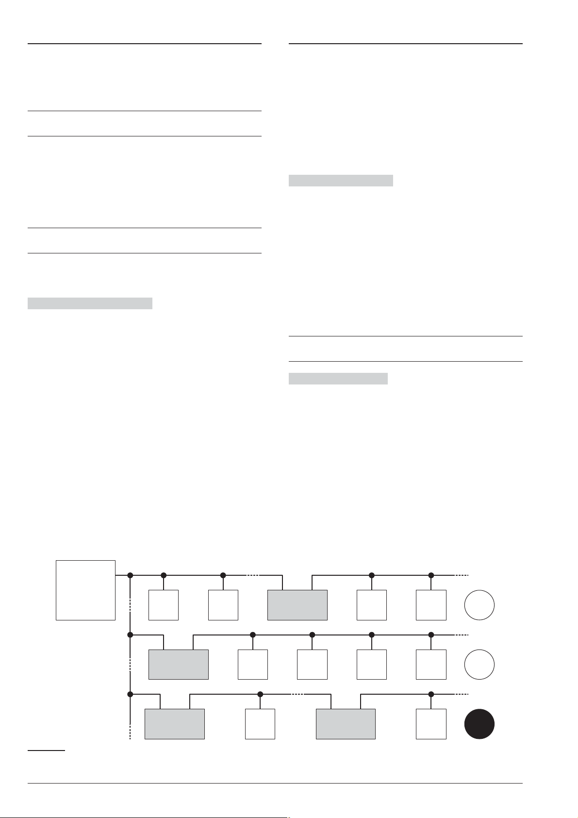
Wiring
Yes
Yes
NO
BPI
device
Panel
Power
station
BPI
device
BPI
device
BPI
device
BPI
device
Power
station
BPI
device
BPI
device
BPI
device
BPI
device
Power
station
BPI
device
Power
station
Connecting BPI Bus Devices
The section describes how to wire the Control Panel,
BPI bus peripherals and various security devices.
Each wiring diagram refers to a specific type of device
(BPI bus devices, Detectors and Signalling devices).
Use shielded cable for all connections, with one
+
end connected to negative and the other floating.
The end of the stranded conductor must not be
!
soldered in places where it is subject to contact
pressure.
The Mains wiring must comply with the rules
!
for double or reinforced insulation.
Use an adhesive cable grip to secure the wires to
+
the terminal boards.
The wiring diagrams show some of the many tailored
solutions this system provides.
About the Wiring Diagrams The locations of the ter
minals in the wiring diagrams may be different to those
on the board.
The Zone terminals may belong to the Control Panel,
Ø
the Keypads or the Input/Output Expanders;
Ø The Output terminals may belong to the Control
Panel or the Input/Output Expanders;
Ø the Input zone and the Open-Collector Output termi-
nals (in the wiring diagrams) can be found on the
Main Unit or Expanders;
Ø only the terminals required for the connection are
shown in the wiring diagrams.
The BPI bus supports the following devices:
LCD Keypads
Ø
Touch Keypads
Ø
Key Readers
Ø
Input Expanders
Ø
Output Expanders
Ø
Power stations
Ø
The maximum number of devices supported depends on
the type ofcontrol panel, as shown in Table 1 on page 6.
Electrical Connections The BPI bus devices must be
connected in parallel to terminals [+], [C], [R], [–] on the
Main Unit, as shown in Figure 8.
The Power Station has two groups of terminals for the
BPI bus connection: the BPI-IN group — for the Power
Station; and the BPI-OUT group — for the BPI devices
connected downstream of the Power Station.
The two groups of terminals are electrically isolated,
therefore, all the cables and devices connected down
stream of the Power Station will not load the Control
-
Panel BPI bus.
Refer to the Power Station Instructions leaflet for further
details.
Only one Power Station can be connected to each
+
shunt of the Control Panel BPI bus (see Fig. 9).
Assigning Addresses You must assign an Address to
each of the BPI bus devices. The assigned Address will
allow the Control Panel to distinguish one device from another. The Peripheral devices are divided into types:
Keypads, Readers, Input/Output Expanders and Power
Stations.
Devices of the same type (e.g. two Readers) must have
different Addresses.
Devices of different types (e.g. a Keypad and a Reader)
are intrinsically different, therefore, may have the same
Address. The BPI bus peripheral Addresses can be as
signed in any order.
Table 5 shows the configuration of microswitches for the
assignment of addresses to the Input/Output Expansions,
the Readers, and the Power Feeding Stations: read the
keypads’ instructions in order to set their address.
-
-
Figure 9 Connecting a Power Station.
ABSOLUTA INSTALLING 27
Page 28

Setting the BPI Level The BPI Level determines the
maximum voltage the BPI bus can carry. Some BPI de
vices have 5 V and 12 V options.
This Control Panel operates at 12 V, therefore, all
+
the peripheral devices must be set at 12 V.
Refer to the BPI device instructions for the BPI Level
setup.
BPI bus Wiring Limitations
n
Due to Voltage drops and stray capacitance caused by
the Control Panel BPI bus connections, the following
wiring limitations must be respected:
the maximum wire length between the Control
Ø
Panel and the BPI peripheral must not exceed 500
metres;
the overall wire length of the Control Panel BPI bus
Ø
must not exceed 1000 metres.
In order toallow the BPI peripherals to operate properly,
11.5 V or more must be present across terminals [+]
and [–]. If a lower voltage is present, it can be boosted
by:
increasing the wire size that supplies the Control
Ø
Panel BPI device (the wires that connect [+] and [–]
of the Control Panel to terminals [+] and [–] of the BPI
device);
Ø connecting some of the BPI peripherals downstream
of a Power Station (these devices will be powered by
the Power Station, therefore, will not load the Control
Panel BPI bus);
Ø using a Power Station to provide the voltage for the
BPI peripheral load.
The cable length downstream of a Power station
+
should not to be included the overall wire length for
the Control Panel BPI bus.
Connecting Detectors
You can connect the detectors to:
terminals L1, L2, L3 and L4 of the Control Panel;
Ø
terminals T1, T2, T3 and T4 of the Control Panel, if
Ø
programmed as Input Lines (Zones);
terminals T1, T2 and T3 of the T-Line and PREMIUM
Ø
keypads, depending on the programmed operating
mode (refer to the keypad instructions for more infor
mation);
Grade 3 detectors CANNOT be connected to the
3
Keypads.
terminals T1, T2, T3, T4, T5 and T6 of the Input/Out
Ø
put Expander M-IN/OUT, depending on the pro
grammed operating mode (refer to the M-IN/OUT’s
instructions for more information).
The following terminals can be used for the power sup
ply to the detectors.
[+F] and [M] (negative) for each pair of Input Lines
Ø
(Zones) on the Control Panel: 13.8 V positive is
present on [+F] terminals — protected by resettable
fuse (0.4 A).
[+F] and [M] (negative) for each pair of Input Lines
Ø
(Zones) on the M-IN/OUT Input/Output Expander:
13.8 V positive is present on [+F] terminals — pro
tected by resettable fuse (0.4 A).
Ø [+F] and [–] (negative) for three Input Lines (Zones)
on the T-Line and PREMIUM Keypad: 13.8 V posi-
tive is present on [+F] terminal — protected by
resettable fuse (0.4 A).
Each zone can support several detectors. However, if
more than one detector is connected, the Control Panel
will be unable to identify the detector in the event of an
Alarm.
-
-
-
-
-
The Control Panel can detect Alarm, Tamper and
Short-circuit on hardwired zones:
Ø
Zone Alarm will be signalled by an Alarm on zone
event;
Ø
Zone Tamper will be signalled by a Tamper on zone
event;
Ø
Short-circuit will be signalled by a Tamper on zone
event.
3
Grade 3 Control Panels and the Input/Output Ex
pander are ALSO able to detect and report the
Grade 3 detector faults.
Resistance
¥ STANDBY ALARM ALARM TAMPER TAMPER ¥
N/A N/A N/A N/A N/A FAULT 24.2 KW
10 KW ALARM ALARM STANDBY ALARM ALARM 8.2 KW
5KW ALARM ALARM SHORTED STANDBY STANDBY 2.2 KW
0 ALARM STANDBY SHORTED SHORTED SHORTED 0
Table 6 Balance Types: the Resistance column shows the resistance across the Zone terminal and the Negative dur
ing the corresponding status (¥ indicates that the terminal is open; 0 indicates that the terminal is shorted to negative).
NO NC SEOL DEOL TEOL
BALANCE TYPES (SUPERVISION) Grade 3
Resistance
-
-
28 Expandable Hybrid Control Panel
Page 29
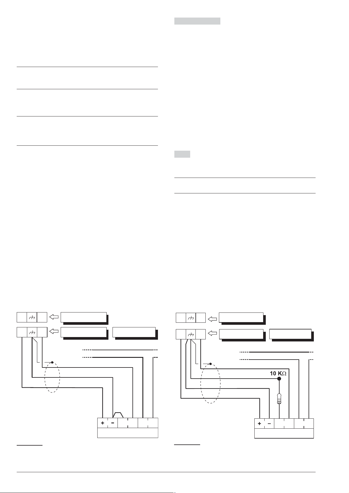
The Zone status depends on several parameters (refer
Detector
N. C. A.
L1
+F
S.
Panel
tamper line
Keypad
Input Expander
T1
+F
Detector
N. C. A.
L1
+F
S.
tamper line
Panel
Keypad
Input Expander
T1
+F
to “Zones” in the “PROGRAMMING FROM PC” sec
tion). This section refers to the Balance type. If only this
parameter is considered, the zone status will depend on
the resistance between its terminal and negative, as
shown in Table 6.
Triple End of Line Supervision is ONLY available
3
on Grade 3 Control Panels and Input/Output Ex
panders.
The following paragraphs describe the connections of
various types of detectors.
The Control Panels are supplied with the necessary
+
resistors to achieve the types of balancing sup
ported: refer to “INTRODUCTION > Control Panel
versions > Grade 3 Control Panels/The Main Boards.
Normally Closed The wiring diagram in Figure 10 il
-
-
-
lustrates the connection of a detector to a Zone with
Normally Closed supervision.
Normally Closed supervision will allow the Control
Panel to detect Alarm status on the zone:
the zone will hold Standby status whilst connected to
Ø
negative;
the zone willtrigger Alarm under all other conditions.
Ø
To provide Tamper detection on zones with Normally
Closed supervision:
either connectthe detector tamper contact to the Con
Ø
trol Panel Tamper Line — this typeof connection does
not provide identification of the tampered detector;
or connect the detector tamper contact to a 24h zone
Ø
— this type of connection requires two zones — one
for Alarm detection, and the other for Tamper detec
tion (refer to “Connecting Tamper Contacts”).
-
-
-
Connecting Motion Detectors
n
Most Motion detectors have Normally-Closed Contacts
(NC in the wiring diagrams), and Normally-Closed Tam
per Contacts (AS in the wiring diagrams).
The wiring diagram depend on the selected supervi
sion. This Control Panel supports the following supervi
sion:
Ø Normally Open;
Ø Normally Closed;
Ø Single End Of Line Resistor (SEOL);
Ø Double End Of Line Resistor (DEOL).
Figures 10, 11 and 12 show the wiring diagram for each
Supervision type. In these figures:
Ø [+] and [–] terminals represent the positive and nega-
tive terminals;
Ø [NC] terminals are the Normally Closed Alarm Con-
tacts of the detector;
Ø
[AS] terminals are the Normally Closed Tamper Con
tacts of the detector.
SEOL The wiring diagram in Figure 11 illustrates the
connection of a detector to a Zone with SEOL supervi
-
-
-
-
sion.
The 10 KW resistor must be connected to the last
+
detector of the zone.
SEOL supervision will allow the Control Panel to detect
Alarm and Short-circuit on the zone:
Ø the zone will hold Standby status when connected to
negative via a 10 KW resistor;
Ø the zone will trigger short-circuit when connected to
negative;
Ø the zone willtrigger Alarm under all other conditions.
To provide Tamper detection: connect the Tamper contact of the detector to the Control Panel Tamper Line, or
to a 24h zone (refer to “Connecting Tamper Contacts”).
-
Figure 10 Connecting a Detector to a zone with Nor
mally Closed supervision.
ABSOLUTA INSTALLING 29
-
Figure 11 Connecting a Detector to a zone with SEOL
supervision.
Page 30
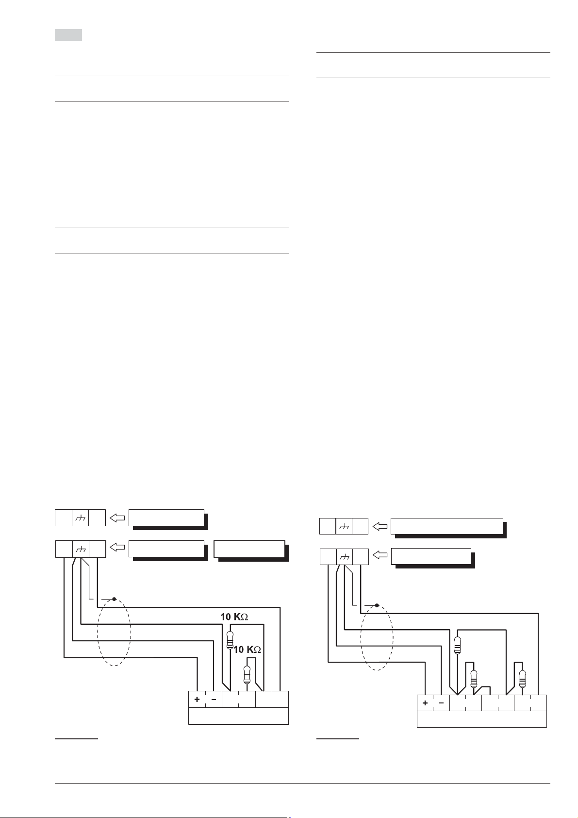
DEOL The wiring diagram in Fig. 12 illustrates the con
Detector
N. C. A.
L1
+F
S.
Panel
Keypad
Input Expander
T1
+F
Grade 3 Detector
N. C. A.Fault
L1
+F
S.
Grade 3 Panel
Grade 3 Input Expander
T1
+F
2,2 KW
22 KW
8,2 KW
nection of a detector to a Input Line (Zone) with DEOL
supervision.
The 10 KW resistors must be connected to the last
+
detector of the zone.
DEOL Supervision will allow the Control Panel to detect
zone Alarm, Tamper and Short-circuit:
the zone will hold Standby status whilst connected to
Ø
negative via a 5 KW resistor (i.e. using two 10 KW re
sistors connected in parallel);
the zone will trigger short-circuit when connected to
Ø
negative;
the zone will trigger Tamper when open;
Ø
the zone willtrigger Alarm under all other conditions.
Ø
Zones with DEOL supervision can detect and sig
+
nal Alarm and Tamper by means of just two wires.
Connection of Grade 3 detectors
-
-
-
n
This type of connection is only possible with Grade 3
3
Control Panels and Input/Output Expanders.
The wiring diagram in Figure 13 illustrates the connec
tion of a Grade 3 detector to a Input Line (Zone) with
Triple End of Line supervision (refer to “PROGRAM
MING FROM THE PC > Zones”).
In addition to the contacts for signalling tampering and
alarms, Grade 3 detectors are equipped with a contact
that is normally closed for reporting faults, such as
masking (Fault in Figure 13).
Tripe End of LIne Supervision will allow the Control
Panel to detect zone Alarm, Tamper, Fault and
Short-circuit:
the zone will hold Standby status whilst connected to
Ø
negative via a 2,2 KW resistance;
the zone will trigger short-circuit when connected to
Ø
negative;
the zone will trigger Tamper when open;
Ø
the Zone will trigger Fault when connected to nega
Ø
tive with a resistance of 24.2 KW (i.e. the series of the
resistors from 2.2 KW and 22 KW);
the Zone will trigger Alarm when connected to nega
Ø
tive with a resistance of 8.2 KW (i.e. series of the
2.2 KW resistor with the parallel of the resistors from
22 kW and 8.2 kW).
-
-
-
-
Figure 12 Connecting a Detector to a zone with DEOL
supervision.
30 Expandable Hybrid Control Panel
Figura 13 Connecting a Detector to a zone with Triple
End of Line Supervision.
Page 31
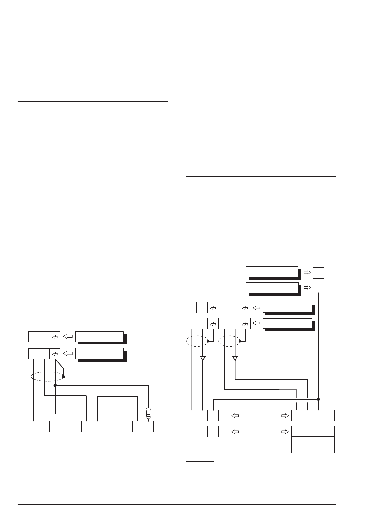
Connecting Roller-Blind and Vibration Detectors
Roller Blind
or Vibration
Detector
N.L1C.
L2
Control Panel
N.
C.
N.
C.
T1 T2
Input Expander
Programming:
L1/T1: N.C. (Normally Closed)
L2/T2: SEOL Supervision
Roller Blind
or Vibration
Detector
Roller Blind
or Vibration
Detector
10 KW
Fire
detector
+F L2 +F L3
O1
Esp. Uscita
DiodeDiode
+F T2 +F T3
T1
Centrale
Output Expander
Control Panel
Control Panel
Input Expander
235
L1 RL2L
*
600 Series
ZT100PL
*
Fire
detector
235
L1 RL2L
n
Zones 1 through 8 of ABSOLUTA support Roller-blind
and Vibration detectors. The zones must be pro
grammed respectively with either the Vibration or
Roller blind option and can be set up as Normally
Closed, SEOL or DEOL supervision (refer to “PRO
GRAMMING FROM THE PC > Zones”).
The wiring diagram in Figure 14 shows a typical con
nection.
The 10 KW EOL Resistor must be connected to the
+
last device.
Connecting Fire Detectors
n
The ABSOLUTA can also manage Fire detectors that
-
-
-
can operate with a supply voltage of 12 V and are
equipped with alarm repeat outputs (such as BENTEL
SECURITY 600/ZT100 Series). The Fire detectors can
be connected using the MUB-RV relay base. Alterna
tively, connect the Alarm Repeat outputs of the Fire de
tectors [R]/[3] to an Input Zone programmed as Fire
(Normally Open and 24h), inserting a diode in series
as shown in Figure 15 (600 series ONLY). Connect the
detector positive [L1]/[2] to terminal [+F], and connect
the detector negative[L]/[5] toan open-collector output.
The open-collector output must be programmed as
Monostable, Normally Closed, 20 seconds ON Time
and assigned to an event that will reset the Fire Detec
tors (e.g. Control Panel Reset or Partition Reset). The
connections described result in the power supply to the
Fire Detectors being cut off for 20 seconds each time
the event occurs, thus allowing the detectors to reset.
Inputs connected to fire detectors do not meet the
A
EN50131-1 and EN50131-3 standards as they are
not covered by the same standards.
-
-
-
Figure 14 Connecting Vibration Detectors and Roller
Blind contacts: connecting one detector to a Normally
Closed zone and connecting two detectors to a SEOL
Supervision zone.
ABSOLUTA INSTALLING 31
Figure 15 Connecting 2 Fire Detectors to a Zone with
Normally Open supervision (* with series 600 ONLY).
Page 32
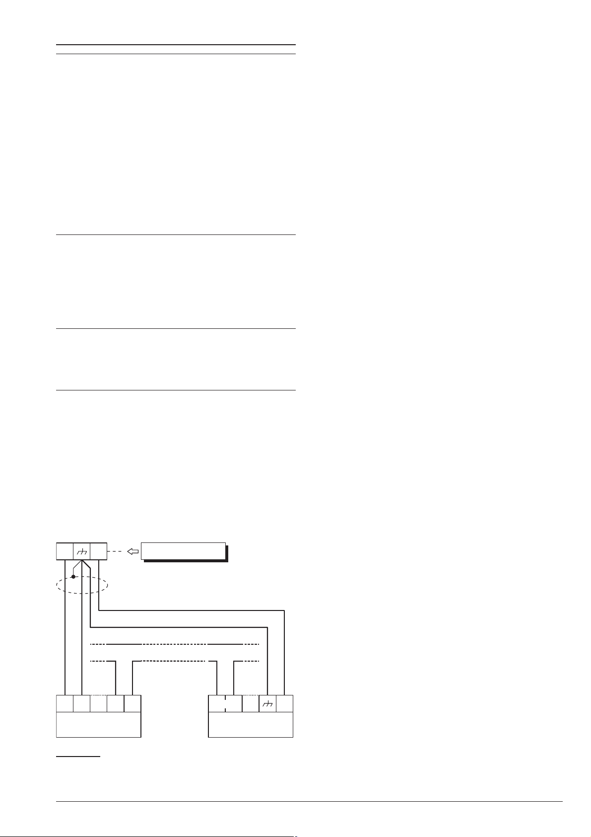
Connecting Alarm Signalling Devices
+A +N
self-powered
siren
A.
S.
AS1 AS2
GND
+B
indoor
siren
tamper line
+N
Control Panel
The panel, to complies the EN50131-1 and
A
EN50131-3 standards, supports the following noti
fication options:
A) 2 sirens with remote power supply + panel
built-in telephone communicator;
B) 1 self-powered siren + panel built-in telephone
communicator;
C) panel built-in telephone communicator + exter
nal telephone communicator with at least ATS-1
grade performance, according with the EN50131
and EN50136-1-1-1 standards (Grade 2 Control
Panels only);
D) external telephone communicator with at least
ATS-3 grade performance, according with the
EN50131 and EN50136-1-1-1 standards.
The ABSOLUTA Control Panel is equipped with three
outputs to connect the Alarm Signalling Devices:
the terminals NC, COM, NO, +N and +A are relevant
Ø
to the output no. 1;
the terminal O1 is relevant to the output no. 2;
Ø
the terminal O2 is relevant to the output no. 3.
Ø
At default, The O2 open-collector output is active in
A
case of trouble. If this setting is not changed, to
maintain compliance with the EN50131-1 and
EN50131-3 standards, you must NOT connected
additional and self-powered sirens to this output.
Alternatively, you can connect the Alarm Signalling Devices to:
Ø terminals T1, T2, T3 and T4 of the Control Panel, if
programmed as Outputs;
Ø terminals T1, T2, T3, T4, T5 and T6 of the Input/Out-
put Expander M-IN/OUT, depending on the programmed operating mode (refer to the M-IN/OUT’s
instructions for more information).
Alarm Signalling Devices, such as: Self-Powered Si
rens, Indoor Sirens, Telephones Diallers, etc., can be
classified as follows:
Intrinsic Security Devices (e.g. Self-Powered Si
-
-
Ø
rens) activated by voltage failure on the respective
terminal;
Positive Alarm Line devices (e.g. Indoor Sirens) ac
Ø
tivated by positive (12 V) on the respective terminal;
Negative Alarm Line devices activated by negative
Ø
(0 V) on the respective terminal;
Supervised Alarm Line devices activated by im
Ø
pedance unbalance on the respective terminal.
The wiring diagram depend on the Alarm Signalling De
vice to connect.
The wiring diagram in Figure 16 illustrates connection
of a Self-powered Siren and an Indoor Siren to Output
no. 1 on the Control Panel:
Output no. 1 on the Control Panel is programmed as
Ø
Normally Closed;
[+N] is the positive power and Input of the Self-pow
Ø
ered Siren. The Siren will activate when positive
(13.8 V) fails on the [+N] terminal;
[+B] is the positive power and Input of the Indoor Si
Ø
ren. The Siren will activate when positive (13.8 V) is
applied to the [+B] terminal;
[M] and [GND] are the negative power terminals of
Ø
the Self-powered Siren and Indoor Siren;
Ø [A.S.] and [AS1-AS2] are the Normally Closed Tam-
per contacts ofthe Self-powered Siren and Indoor Si-
ren.
To provide Tamper detection: connect the Signalling
device Tamper contact to the Control Panel Tamper
Line or to a 24h zone (refer to “Connecting Tamper
Contacts”).
-
-
-
-
-
-
-
Figure 16 Connecting a Self-powered Siren and an In
door Siren to Control Panel Output no. 1.
32 Expandable Hybrid Control Panel
-
Page 33
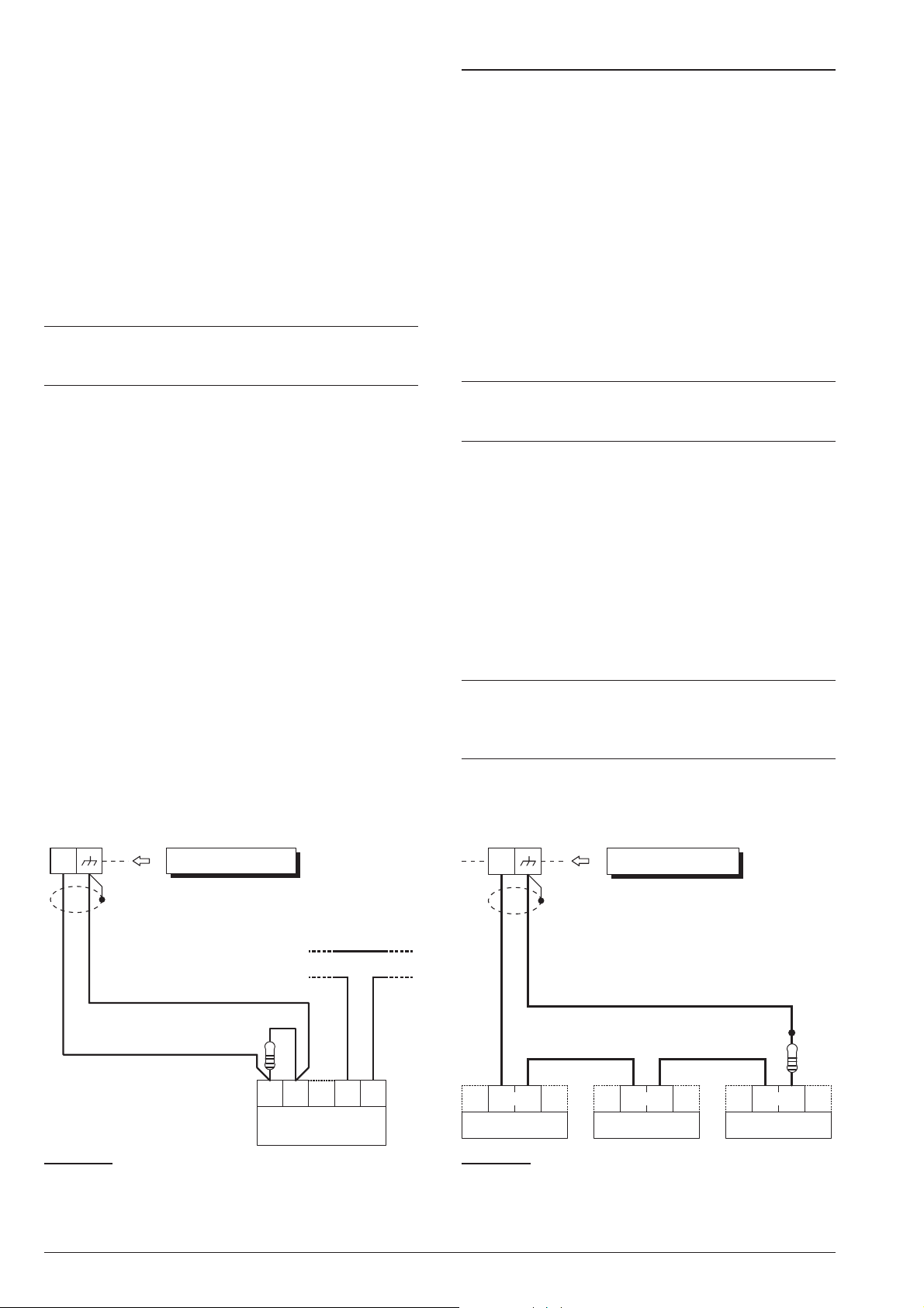
Supervised Output
tamper line
AS1 AS2
GND
+B
indoor
siren
+A
Control Panel
2.2 KW
A.
S.
AS
A.
S.
A.
S.
Control Panel
10 KW
n
Output no. 1 can be set up as Supervised Output. This
type of output must be programmed as Normally
Closed (refer to “Attributes” under “Outputs” in the
“PROGRAMMING” section). The Control Panel can de
tect short-circuit and connection interrupt to terminals
+A of output with this attribute. The wiring diagram in
Figure 17 illustrates the connection of an Indoor Siren to
the Supervised Output using a 2.2 KW across terminals
+A and negative.
The 2.2 KW resistor (included in the package) have 3
red bands and a gold band. The last band (gold) indi
cates the tolerance, therefore, it may be a different
colour.
The 2.2 KW resistor must be connected to the last
+
device on the Output, otherwise it will have no ef
fect.
Short-circuit and connection interruption to terminal +A
of Supervised Output, will be signalled by:
Tamper on supervised output — relative to the
Ø
Output;
flashing on the a indicator on the Keypads.
Ø
Connecting Tamper Terminals
The Tamper contacts of the security system devices
can be connected to the SEOL Supervised 24h Tamper
-
-
-
Line.
The Tamper Line terminal is marked AS:
The Tamper Line will hold Standby status when con
Ø
nected to negative via a 10 KW resistor;
The Tamper Line will trigger an Alarm under all other
Ø
conditions.
Alarm on the Tamper Line will be signalled by:
a Tamper on Main unit event (by default, to comply
Ø
with EN50131, the Tamper on External Siren event
will occur);
flashing on the T indicator on Keypads.
Ø
The T indicator will flash until the cause of Alarm is
+
cleared (memory). The T indicator will stop flash
ing when the Control Panel resets.
The wiring diagram in Figure 18 illustrates the connec
tion of 3 Tamper contacts to the Control Panel Tamper
Line:
-
-
-
1. connect the device tamper contacts in series;
2. connect a 10 KW resistor in series to the last Tam-
per contact;
3. connect one end of the series to the [AS] terminal
and the other to the [M] terminal.
The 10 KW resistor must be connected to the last
+
device on the tamper line.
If the Tamper line is not used, connect a 10 KW resistor across terminals [AS] and [M].
Figure 17 Connecting an Indoor Siren to a Supervised
Output on the Control Panel.
ABSOLUTA INSTALLING 33
Figure 18 Connecting 3 Tamper contacts to the Con
trol Panel Tamper Line — the [A.S.] terminals represent
the Normally Closed Tamper contacts of the device.
-
Page 34
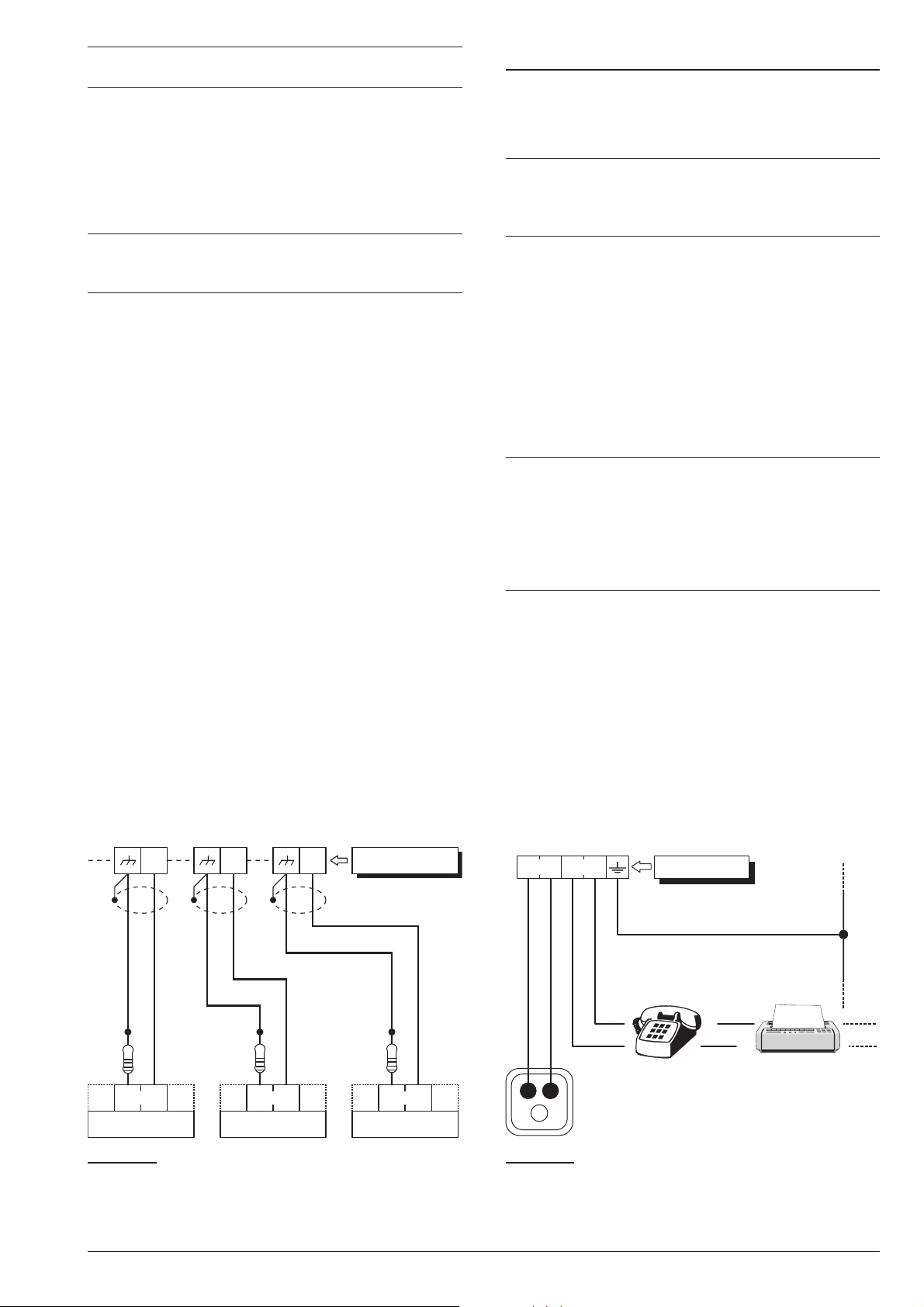
If several contacts are connected to the Tamper
L2
A.
S.
A.
S.
A.
S.
10
KW
L4 T1
Control Panel
10
KW
10
KW
Telephone
plug
a
LE LI
Mains
earth
This connection
is necessary!
Control Panel
b
c
+
Line, the tampered device will be unidentifiable.
To identify tampered devices:
select DEOL Supervision for motion detector con
Ø
nections (refer to “DEOL” under “Connecting Motion
Detectors”);
connect each Tamper contact to a 24h zone with
Ø
SEOL Supervision (see Figure 19).
Tamper contact zones can be programmed with
+
Normally Closed Supervision, in which case, the
10 KW resistors must not be connected.
Connecting the Telephone Line
In order to allow use of the Dialler and Digital communi
cator, the telephone line must be connected to termi
-
nals [LE], as shown in Figure 20.
In order to comply with the EN50131-1 and
A
EN50131-3 standards, the Vocal Telephone Dial
ler and/or the Digital Communicator must be
enabled.
The Control Panel can detect Telephone line trouble
(Line down), which will be signalled when thevoltage on
the [LE] terminals drops below 3 V for over 45 seconds.
Telephone line trouble will be signalled by:
the Line-down event;
Ø
ON status of the G indicator on Keypads;
Ø
flashing on the i indicator on Keypads.
Ø
The Control Panel will signal restoral when the voltage
on the [LE]terminals returns to 3 V for over 15 seconds.
If the telephone line IS NOT CONNECTED to the
+
Panel, the Telephone Line check option must be
DISABLED. If it is not Disabled, the Control Panel
will signal Line-down status persistently (refer to
“PSTN options” in the “PROGRAMMING FROM
THE PC” section). By default this option is
disabled.
-
-
-
Connect Line-sharing devices (Fax, Answerphone,
etc.) to the [LI] terminals. This will allow the Control
Panel to take priority ONLY in the event of an alarm.
Connect the [-] terminal to the Mains Earth — this will
protect the PCB against surges from the Telephone
line.
Ensure that the Mains Earth is fully intact and
!
operating properly before connecting the Tele
phone line.
-
Figure 19 Connecting 3 Tamper contacts to three 24h
Zones with SEOL Supervision — the [A.S.] terminals rep
resent the Normally Closed Tamper Contact of the device.
34 Expandable Hybrid Control Panel
-
Figure 20 Connecting the Telephone Line to the Con
trol Panel.
-
Page 35
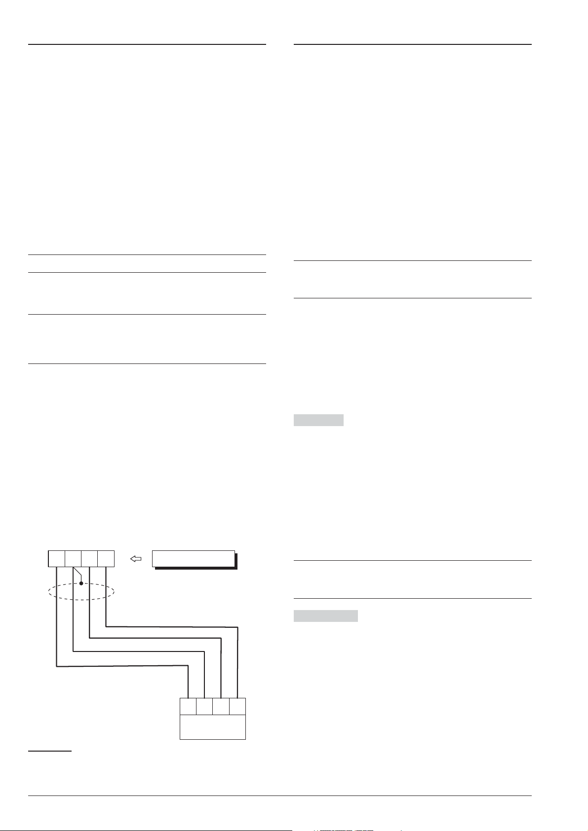
Connecting the AS100 Audio Station
S M
B
R
AS100
RED
Control Panel
BLKSPKMIC
Yellow
White
Black
Red
Power Supply
The AS100 (accessory item) is a 2-way audio station
that include a speaker and a microphone.
By means the AS100:
the Installer can record and playback the Voice Mes
Ø
sages (refer to “2.1 Voice Message Recording” in the
“KEYPAD OPERATION” section);
the User can perform some audio functions by a re
Ø
mote telephone (refer to “OPERATING THE
SYSTEM FROM A TELEPHONE” in the User Man
ual);
the user can have an audio feedback on the security
Ø
system status (refer to “Event and Actions” in the
“PROGRAMMING FROM THE PC” section).
the Central Station operator can perform an audio
Ø
verification of the alarm event.
This Control Panel support ONE AS100.
+
Refer to the diagram in Figure 21 for the connection of
the AS100 to the Control Panel’s Main Board.
The audio station AS100 is NOT certified
A
IMQ-SECURITY SYSTEMS and therefore does
not conform to the EN50131-1 and EN50131-3
standards.
In order to comply with the Safety regulations
!
in force, the Mains must be equipped with a bi
polar isolating device for protection against
over voltage and short-circuit to Earth, in
-
-
-
stalled outside the control panel and easily ac
cessible, with minimum contact distance of
3 mm (e.g. automatic isolating switch).
The ABSOLUTA is powered from the Mains (230V/50 Hz)
through aSwitching power supply, located inside thecab
inet. The cabinet can also house a backup battery (not in
cluded) for power backup during Mains failure.
Mains failure will be signalled by the:
OFF status of indicator on the Power Supply;
Ø
ON status of the G indicator on Keypads;
Ø
Warning Mains failure event.
Ø
The Warning Mains failure event will be signalled
+
after the programmed delay (refer to “Filter Times”
in the “PROGRAMMING FROM PC” section).
The panel reports a fault when the output voltage drops
below 11.2 V, with:
ON status of the G indicator on Keypads;
Ø
Ø the message Panel low Vout on the LCD
Keypads, in View Signals mode.
-
-
-
-
-
The Control Panel will monitor the battery at all times,
(refer to Static Test and Dynamic Test).
Static Test The Static Test monitors the battery
charge during Mains failure. Low battery status (below
11.4 V) will be signalled by the:
Ø Low battery event;
Ø ON status of the G indicator on Keypads.
If this occurs, the Mains power must be restored before
the batteryempties, otherwise, the system will shutdown.
Low battery restoral (over 12.3 V) will be signalled by:
Ø
the end of the Warning low battery event;
Ø
The G indicator on Keypad turn OFF only after the
reset of all events (the events stay in memory).
The Control Panel automatically shuts down when
+
the battery voltage drops below 9.6 V to protect the
battery from permanent damage.
Dynamic Test The Dynamic Test monitors the oper
ating capacity of the battery. A failed test (battery does
not meet the Test requirements) will be signalled bythe:
Ø
Warning power trouble event;
Ø
ON status of the G indicator on Keypads.
-
If this occurs, the backup battery must be replaced im
mediately, otherwise, the system will be unable to func
Figure 21 Connecting the AS100 to the Control Panel.
tion in the event of Mains failure (black-out).
Battery trouble restoral will be signalled by the:
Ø
end of the Warning power trouble event;
Ø
The G indicator on Keypad turn OFF only after the
reset of all events (the events stay in memory).
ABSOLUTA INSTALLING 35
-
-
Page 36
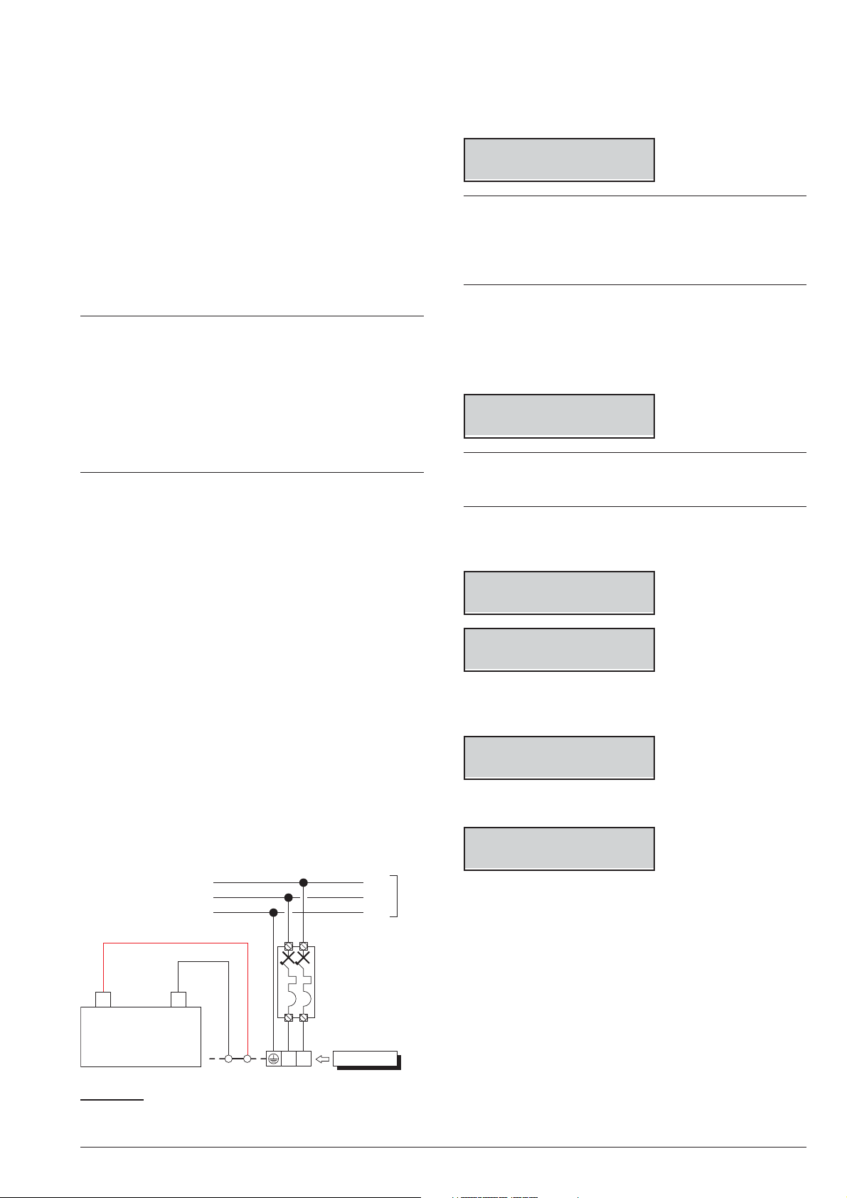
Power connection
L
Panel
N
Automatic
Isolating
Switch
+
–
Backup Battery
Line
Neutral
Earth
230 V
50 Hz
n
Work carefully through the following steps (refer to
“Parts Identification”).
1. Locate the backup battery on its housing 33.
Auto-configuration (Wizard setup)
n
Each time you power up the control panel, the LCD
keypads will show the following message, for approxi
mately 15 second, indicating that the Control Panel is
performing the Auto-configuration:
-
2. Connect the backup battery to the connector 13 on
the Main Board, by means the cable 30.
3. Connect the Earth wire to the [Q] terminal on the
power supply terminal board.
4. Connect the Neutral wire to terminal [N], and the
Line wire to terminal [L] on the power supply termi
nal board.
The Control Panel Tamper Switch is enabled by
+
the initial closure of the Control Panel. Therefore, it
cannot trigger a Tamper on Panel event on first
power up. Likewise, if the Panel is opened during a
programming session (via Keypad or computer),
the Tamper switch will be inhibited thus unable to
trigger a Tamper on Panel event until the Pro
gramming session ends, and the Panel is closed
again.
Power disconnection
n
To disconnect the power, proceed as described below
(see “IDENTIFICATION OF PARTS” on pages 15, 16
and 17).
CALL
SERVICE
If you are performing the Hardware Default, the LCD
+
Keypads show the message “RemoveJumpPCLInk”
that remember to you to remove the short circuit on
the PC-LINK connector (refer to “Hardware Default”
-
for further details).
During this phase the Control Panel will enroll the BPI
Bus peripherals.
Termination of this phase will be indicated on the LCD
Keypads as follows:
Presse,Presiona
-
Premi,Push ENTER
Press ENTER once and wait a few moments for the
+
next message to appear: the time taken will depend
on the number of devices connected to the BPI bus.
1. When you press ENTER, the display will show the
available languages:
1. Disconnect the Neutral [N] and Line [L] on the
Power-Supply terminal board.
2. Disconnect the Earth wire [Q].
3. Wait for the control panel to signal the lack of main
voltage, with:
Ø
the keypad light indicator G;
Ø
the message Panel NO 220v on the keypads, in
view signals mode (see “View Signals” in the USER
MANUAL).
4. Disconnect backup battery cable 30 from connec
tor 13 of the Motherboard.
-
Mod. Lingua 1/9
1=Italiano
Modify Lang. 2/9
2=English
2. Select the required language by enter the relative
number:
Panel ID
0000
3. Enter the Panel ID then press ENTER:
Kb=01 Kr=00 Al=0
Ei=00 Eo=00 OK?
The keypad shows the enrolled BPI devices as follow:
Ø
Kb are the Keyboards;
Ø
Kr are the Key readers;
Ø
Al are the Power Stations;
Ø
Ei are the Input Expanders;
Ø
Figure 22 Connecting the Mains power.
Eo are the Output Expanders.
4. Press ENTER if the display configuration is right
and go to the next step, or check the connection
and the address of the missed BPI peripherals,
then press OFF and ESC, and go back to the step
1.
36 Expandable Hybrid Control Panel
Page 37

Zone Term. 008
DDDDrrrr Board
The line at the top shows the zones available (8 in the
example).
The bottom line shows the standby status and the su
pervision relevant to the zones on the device indicated
on the right side, as follow:
–, the zone is not used;
Ø
O, the zone is Normally Open, Not Supervised;
Ø
C, the zone is Normally Closed, Not Supervised;
Ø
S, the zone is Normally Closed and Supervised with
Ø
a Single End of Line Resistance;
D, the zone is Normally Closed and Supervised with
Ø
a Double End of Line Resistance;
T, the zone is Normally Closed and Supervised with
Ø
a Triple End of Line Resistance (Grade 3 Control
Panels ONLY);
r, the zone is Reserved;
Ø
X, the relative terminal is an output;
Ø
Board are the zones on the Main Board;
Ø
Ein01 are the zones on the Input Expander 01.
Ø
5. Press the number relative to a Zone to change its
standby status and supervision option: press 1 for
zone terminal T1, 2 for zone terminal T2 e so on;
press the number until the display shows the re
quired option.
Press the key A or B to change the options for all
terminals.
Press the key C or D to select the device.
Press ENTER when the display shows the required
standby status for each zone:
Delayed Zone 000
iiiiiiii Board
The M letter next to a zone indicates that the zone’s
+
delay options (Entry Delay and Exit Delay) were
changed by BOSS, in a configuration DOES NOT
supported by the Wizard Setup then NOT modifi
able by the Wizard Setup.
-
6. Press the number relative to a Zone to change its
Delayed option: press 1 for zone terminal T1, 2 for
zone terminal T2 so on; press the number until the
display shows the required option.
Press the key C or D to select the device.
Press ENTER when the display shows the required
Delayed option for each zone:
-
Int. Zone 008
IIIIIIII Board
The top line shows the number of Internal Zones.
The bottom line shows the status of the Internal Option
for each zone on the device indicated on the right side,
as follow:
–, the zone is not used;
Ø
I, the zone is Internal;
Ø
r, the zone is Reserved;
Ø
E, the zone is NOT Internal (Normal);
-
Ø
Board are the zones on the Main Board;
Ø
Ø Ein01 are the zones on the Input Expander 01.
7. Press the number relative to a Zone to change its
Internal option: press 1 for zone terminal T1, 2 for
zone terminal T2 e so on; press thenumber until the
display shows the required option.
Press the key C or D to select the device.
Press ENTER when the display shows the required
Internal option for each zone:
The top line shows the number of Delayed Zones.
The bottom line shows the status of the Delayed Option
for each zone on the device indicated on the right side,
as follow:
Ø
–, the zone is not used;
Ø
i, the zone is Instant;
Ø
r, the zone is Reserved;
Ø
D, the zone is Delayed;
Ø
M, the zone has been Modified by BOSS;
Ø
Board are the zones on the Main Board;
Ø
Ein01 are the zones on the Input Expander 01.
The r letter next a zone indicates that it is reserved.
+
These reserved zones are set as Hold-up, Zone
Fault, Internal Siren Fault and External Siren Fault.
TEMPERATURE (°C) -10 -5 0 5 10 15 20 25 30 35 40 45 50
VOLTAGE (V) 14.5 14.4 14.3 14.1 14.0 13.9 13.7 13.6 13.5 13.4 13.3 13.2 13.1
Table 7 Switching Power Supply Output Voltage chart. To find the Output Voltage using the chart: — select the near
est value to the Probe temperature on the TEMPERATURE (°C) row; read the corresponding value on the VOLTAGE
(V) row; adjust the Output Voltage of the Switching Power Supply to the indicated value. For example, if the Probe tem
perature is 22 °C, the Output Voltage of the Switching Power Supply must be set at 13.7 V.
Sep/09/09 09:14
Bentel Absoluta
The top line shows date and time and the bottom line
shows Bentel Absoluta, indicating the end of the
wizard setup.
The configuration can be changed during the pro
+
gramming session.
-
-
-
ABSOLUTA INSTALLING 37
Page 38

Thermal Probe
-10-5 0 5 101520253035404550
13,0
13,5
14,0
14,5
VOLTAGE (V)
TEMPERATURE (°C)
a)
13,7
22
n
The Thermal probe KST (accessory item) will optimize
the backup battery charge process, by regulating the
charge voltage in accordance with the temperature of
the backup battery.
Work carefully through the following instructions to in
stall the Thermal probe (refer to the figures 2 and 3 on
page 16 and 17):
1. Connect the probe to the connector on the power
supply.
Hardware Default
You can restore the Control Panel options to the factory
default by hardware, as indicated below.
You can also restore the factory default by an LCD Key
pad (refer to “Factory Default” in the “KEYPAD OPERA
-
TIONS” section).
You CAN’T perform the Hardware Default if the op
+
tion Lock Installer Code is enabled (refer to “Sys
tem options” in the “PROGRAMMING FROM PC”
section).
-
-
-
-
2. Attach the probe to the backup battery, in such a
way as to obtain optimum heat transfer.
3. Measure the Probe temperature.
4. Using the graph in Figure 23 and/or Table 7, find
the value (in accordance with the battery tempera
ture) that the Switching Power supply output volt
age will be based on.
5. Using the trimmer , adjust the voltage on the termi
nal board to the required value.
If you are connecting a KST thermal probe to a
+
BAQ15T12 Power Supply, ensure that the
BAQ15T12 on-board Jumper is inserted.
For further information, refer to the Insert in the KST
package.
To reset all the Voice Messages, download the au
+
dio file from BENTEL’s website onto a USB key
and then upload the Voice Messages from the USB
key onto the control panel as described in para
graph “2.5) Message Download/Upload via USB
Key”.
-
-
-
1. Short circuit the pins 1 and 2 on the PC-LINK con
nector (10).
2. Remove ALL the control panel power: remove the
power supply connector (12) and the battery con
nector (13).
The self-powered signalling devices will sound.
+
3. Re-connect the control panel power: the LCD
keypads will show the following message
-
-
-
-
Togli PontPCLink
RemoveJumpPCLink
4. Remove the short circuit on the PC-LINK connector: the control panel will perform the Wizard Setup
(refer to “Auto-configuration (Wizard setup)”).
Figure 23 Switching Power Supply Output Voltage graph. To find the Output Voltage using the graph: — indicate the
Probe temperature on the TEMPERATURE (°C) axis; draw a line from the temperature value point up to the curve a);
draw a line from the intersection point across to the VOLTAGE (V) axis; adjust the Output Voltage of the Switching
Power Supply to the resultant value. For example, if the Probe temperature is 22 °C, the Output Voltage of the
Switching Power Supply must be set at 13.7 V.
38 Expandable Hybrid Control Panel
Page 39

PROGRAMMING FROM THE PC
You can program this Control Panel using the BOSS
Console Software that you can download from
www.bentelsecurity.com
Read this section thoroughly to learn how to install and
use the BOSS Console Software.
1. Install the BOSS Console as described in the Help
on line:
www.customer.bentelsecurity.com/boss/eng/
2. Run the BOSS Console Software.
3. Select the Username and enter the corresponding
Password to Login in the relevant session:
the default Username is admin and the Password
is 1234.
4. Select the Account Search option on the Start
Page menu, then select New Account to create a
new account or open an existing account.
5. Setup the options (refer to the respective paragraphs for instructions).
Minimum system requirements
n
To support the prerequisites for BOSS the following
system requirements must be met:
Processor: 600 megahertz (MHz) Pentium III com
Ø
patible or faster processor, 1 gigahertz (GHz) or
faster is recommended;
RAM: 1GB of System Memory;
Ø
Hard Disk: 2.1 GB of available space;
Ø
CD or DVD Drive: Not required;
Ø
Display: 1024 x 768 high colour, 32-bit (Recom
Ø
mended).
-
-
6. Download the options to the control panel (refer to
“Downloading/Uploading”).
The system options are organized in groups. The Op
tion Groups in this section are congruent with the BOSS
application structure.
n
Options with requirements
A
The IMQ/A symbol indicates the option require
ments to comply with the EN50131-1 and
EN50131-3 standards.
-
-
ABSOLUTA PROGRAMMING FROM THE PC 39
Page 40
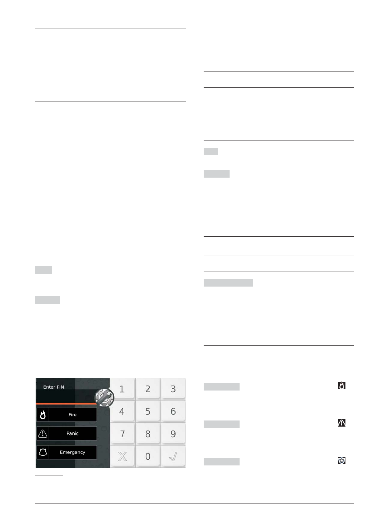
Configuration
On startup the Control Panel will automatically enroll all
the BPI Bus peripherals (refer to “Power supply” under
“INSTALLING”). Any changes after automatic enroll
ment must be made by the Installer.
If a peripheral device has not been connected properly
to the BPI bus, or fails to respond (Device Lost) due to
Trouble or Tamper, an X will be shown above the s icon
on the Keypad, and the Control Panel will generate the
-
following event:
Warning BPI Peripheral
Ø
During the polling process, the Control Panel will com
pare the interrogation result with the stored configura
tion and, in the event of mismatch, will a warning.
If the Control Panel is connected to a computer, it
+
will be possible to view the configuration by up
loading the Configuration page.
The Configuration Group Options is divided into pages
— one for each type of device (Keypads, Expander In,
Expander Out, Key Readers, Power Stations and Wire
less Module).
In the second column, the application shows the list of
supported BPI peripherals, for the type selected in the
first column: the application shows the peripheral ad
dress in bracket followed by the label assigned to.
In the third column you can set the options relevant to
the BPI peripheral selected in the second column.
The following programming instructions refer to options
common to all BPI peripherals. For instructions on how
to program the options of a specific device, refer to the
relevant paragraph.
Label This option (maximum 16 characters) is for the
device label (e.g. Entrance, Kitchen, etc.). This label will
identify the Device in all the operations it is involvedin.
Enabled The devices connected to the BPI Bus must
be Enrolled, otherwise the Control Panel will be unable
to manage them.
-
-
-
-
-
The event will be recorded in the Log (refer to
+
ID.TYPE for the BPI Device Lost event).
Keypads
n
The Keypads option group will allow you to enroll and
set up all the options relating to the keypad.
For information regarding the Enabled and Label
+
options, refer to “Configuration”.
Type Select the type of keypad: LCD or Touch.
Default: LCD.
EN50131 If this option is enabled, in standby mode the
keypad will hide the Control Panel and zone display sta
tus. To display this information, you will have to enter
your own PIN first. In the event ofAlarms, Tampers, and
Troubles, indicator light G will be illuminated, but in or
der to view malfunction information you will have to en
ter your own PIN.
Default: enabled.
In order to comply with the EN50131-1 and
A
EN50131-3 standards, this option must be enabled.
-
-
-
3 This option is ENABLED and locked (cannot be
changed) on Grade 3 Control Panels.
SMS Notification Select the type of notification for
SMS text messages received by the GSM module:
Ø Off, no notification;
Ø
Show Alert, the keypad displays the message SMS
received;
Ø
Show Alter and Sounds, the keypad displays the
message SMS received and beeps (LCD
keypads only).
This option CANNOT be set if the GSM group
+
Present option is not enabled.
Default: Off.
Super Key 1 Enter a label to explain the button on
the Touchscreen Keypad (Figure 24).
Valid values: up to 16 characters.
Default: Fire.
Super Key 2 Enter a label to explain the button on
the Touchscreen Keypad (Figure 24).
Valid values: up to 16 characters.
Default: Panic.
Super Key 3 Enter a label to explain the button on
the Touchscreen Keypad (Figure 24).
Figure 24 Default labels of the Super Keys on the
Touchscreen Keypad.
Valid values: up to 16 characters.
Default: Emergency.
40 Expandable Hybrid Control Panel
Page 41

Partitions Select the Keypad Partitions. The Keypad
will be able to control (Arm, Disarm, etc.) ONLY the En
abled Partitions.
Partitions This option will allow you to assign the
-
Reader to the relevant Partition: the Reader will be able
to Arm the Partition in Away mode.
Keypads need not necessarily be enabled on Parti
+
tions, and can be used for programming, viewing
and other non-command related purposes.
Expander In
n
The Expander In option group will allow you to enroll the
Input Expanders located on the M-IN/OUT Expanders
the PREMIUM and the ABSOLUTA T-Line keypads
connected to the BPI bus
For information regarding the Enabled and Label
+
options, refer to “Configuration”.
Inputs Select the number of inputs on board the de
vice: only the relevant terminals will therefore be dis
played in the Zones option group.
Expander Out
n
The Expander Out option group will allow you to enroll
the Output Expanders located on the M-IN/OUT Ex
panders, on the PREMIUM and ABSOLUTA T-Line
keypads, connected to the BPI bus
For information regarding the Enabled and Label
+
options, refer to “Configuration”.
1
.
1
.
-
-
-
-
Commands performed by the selected Key Reader
+
will affect ONLY the Partitions common to both the
Reader and Key in use.
For example, if you attempt to Arm the system at a
Reader that is enabled on Partitions no. 1 and no. 2,
with a Key that is enabled on Partitions no. 1 and no. 3,
ONLY Partition no. 1 will Arm (Partition no. 1 is common
to both the Reader and Key).
Yellow This option will allow you to set up the A Mode
Arming configuration. If an A Mode Arming request is
made at a Reader, the Partitions will Arm/Disarm in ac
cordance with the programmed configuration, as
follows:
None — the status of the corresponding Partition
Ø
will remain unchanged;
Away Arm — the Partition will Arm;
Ø
Stay Arm — the Partition will Arm in Stay mode (i.e.
Ø
Zones with the Internal Attribute will be Bypassed);
Instant Stay — the Partition will Arm in Stay mode
Ø
with zero Entry Delay;
Disarm — the Partition will Disarm.
Ø
Green As per the Yellow option but for B Mode.
-
Outputs Select the number of outputs on board the device: only the relevant terminals will therefore be displayed in the Outputs option group.
n Key Readers
The Key Readers option sub-group will allow you to enroll and set up Key Readers. You must set up the Options and the Arm Modes for each Partition, as follow.
For information regarding the Enabled and Label
+
options, refer to “Configuration”.
EN50131 If this option is enabled, in standby mode the
Readers’ LED’s are turned off, regardless of the Parti
tion status.
Default: enabled.
A
In order to comply with the EN50131-1 and
EN50131-3 standards, this option must be en
abled.
3
This option is ENABLED and locked (cannot be
changed) on Grade 3 Control Panels.
n Power station
The Power stations page will allow you to enroll and
setup the Power Stations.
For information regarding the Enrolled and Label
+
parameters, refer to the “Configuration” section.
AC Fail Delay Set the delay for the MAINS fault on the
Power Supply Station before it will be signalled.
Valid entries: 0 through 3600seconds, in 1 secondsteps.
Default setting: 0 seconds
A
In order to comply with the EN50131-6 standards,
-
-
this option MUST NOT be more then 60 seconds.
Low Battery Delay Set the delay for the low battery on
the Power SupplyStation (battery voltage below 11.4 V)
before it will be signalled.
Valid entries: 0 through 3600 seconds, in1 second step.
Default setting: 0 seconds
A
In order to comply with the EN50131-6 standards,
this option MUST NOT be more then 300 seconds.
1 The M-IN/OUT Expander is seen as an Input Expander and/or as an Output Expander, depending on how it is
programmed (refer to the M-IN/OUT’s instructions for more information). If the M-IN/OUT Expander is programmed
as an Input and Output Expander, it must be enrolled as an Input Expander and as an Output Expander. For
example, if you have programmed an M-IN/OUT Expander as an Input Expander and Output Expander, and
assigned it address no. 1, you must enroll Input Expander no. 1 and Output Expander no. 1.
ABSOLUTA PROGRAMMING FROM THE PC 41
Page 42

The Control Panel can detect and signal:
forced opening or removal of Power stations;
Ø
interruption of power supply to the Power station;
Ø
the status of Power station batteries;
Ø
the status of Power supply modules;
Ø
the status of Power station Outputs;
Ø
short circuiton the auxiliaryoutputs of the Powerstation;
Ø
low voltage onthe power output of the Power station
Ø
low voltage on the auxiliary outputs ofthe Power station
Ø
Forced opening or removal will be signalled by:
r
the Tamper on BPI Device event (refer to “Events
Ø
2
2
and Actions”);
an X above the b icon on the Keypad, and the
Ø
Power stat tamp. message (refer “View Trou
ble Mode” in the USER MANUAL);
the Event details in the log:
Ø
DESCRIPTION — Tamper on BPI device.
WHERE — The Power Station label.
Mains power failure (interruption) will be signalled by:
r
the Warning mains failure on Power station event
Ø
(refer to “Events and Actions”);
the ON status of the G LED on the keypads, and the
Ø
AC Mains Failure message (refer “View Trou
ble Mode” in the USER MANUAL);
the Event details in the log:
Ø
DESCRIPTION — AC Mains Failure.
WHERE — The Power Station label.
r Low Battery (below 11.4 V — refer to “INSTALLING
> Power Supply > Static Test”) will be signalled by:
Ø the Warning low battery on Power station event
(refer to “Events and Actions”);
Ø the ON status of the G LED on the keypads, and the
Low Battery message (refer “View Trouble
Mode” in the USER MANUAL);
Ø the Event details in the log:
DESCRIPTION — Low Battery.
WHERE — The Power Station label.
r
Battery Trouble (refer to “Dynamic Test” under “Con
necting Power supplies” in the “INSTALLATION”
section) will be signalled by:
Ø
the Warning power trouble on Power station
event (refer to “Events and Actions”);
Ø
the ON status of the G LED on the keypads, and the
Troub. pow. syst. message (refer “View Trou
ble Mode” in the USER MANUAL);
Ø
the Event details in the log:
DESCRIPTION — Troub. pow. syst.
WHERE — The Power Station label.
r
Disconnected Battery
Ø
the Battery not connected on Power station event
3
will be signalled by:
(refer to “Events-Actions” section);
the ON status of the G LED on the keypads, and the
Ø
Batt. disc. pw.s message (refer “View Trou
ble Mode” in the USER MANUAL);
the Event details in the log
Ø
DESCRIPTION — Batt. disc. pw.s
WHERE — The Power Station label
Power supply module trouble
;
.
r
the Battery charger trouble on Power station
Ø
event (refer to “Events and Actions”);
the ON status of the G LED on the keypads, and the
Ø
4
will be signalled by:
Fault chrg.pw.s message (refer “View Trouble
Mode” in the USER MANUAL);
the Event details in the Log:
Ø
-
DESCRIPTION — Fault chrg.pw.s.
WHERE — The Power Station label.
Disconnected Power supply module
r
the Switching not connected on Power station
Ø
5
will be signalled by:
event (refer to “Events and Actions”);
the ON status of the G LED on the keypads, and the
Ø
Swtch.disc.pw.s message (refer “View Trouble
Mode” in the USER MANUAL);
the Event details in the log:
Ø
-
DESCRIPTION — Swtch.disc.pw.s;
WHERE — The Power Station label.
Current draw of a Power station output that exceeds
r
the maximum will be signalled by:
Ø the Short circuit output 1/2/3 on Power Station
event (refer to “Events and Actions”);
Ø the ON status of the G LED on the keypads, and the
Out. short pw.s message (refer “View Trouble
Mode” in the USER MANUAL);
Ø the Event details in the log:
DESCRIPTION — Out. short pw. s.
WHERE — The Power Station label.
r Low voltage on the power output (less than 10.6 V) is
signalled by
Ø
the Low Voltage on Main Power event (refer to
-
“Events and Actions”);
Ø
the ON status of the G LED on the keypads, and the
2
:
PS1 low Vout message, for Power Station No. 1
(refer “View Trouble Mode” in the USER MANUAL).
r
Low voltage on the auxiliary outputs (less than
10.6 V) is signalled by:
-
Ø
the Low Voltage on Output 1 (2 or 3) event (refer to
“Events and Actions”);
Ø
the ON status of the G LED on the keypads, and the
PPS1 Vout1 LOW message, for Output O1 of
Power Station No. 1 (refer “View Trouble Mode” in
the USER MANUAL).
2 Grade 3 Control Panels and Power Stations ONLY.
3 If the battery voltage drops below 10.2V, the Power station will disconnect it automatically. This operation will
prevent damage to the battery.
4 The Power supply module of the Power station will be considered “out-of-order” if its output voltage reaches 0.5 V above, or
drops to 0.5 V below the preset value. If the Power station is not equipped with a Thermal probe, the output voltage will be
13.8 V. If the Power station is equipped with a Thermal probe, the output voltage will depend on the probe temperature.
5 The Power station will disconnect the Power supply module if its output voltage reaches 0.5V above the preset
value.This operation will prevent damage to the peripherals. The power to the peripherals will be provided by the
Power station battery. If the Power station is not equipped with a Thermal probe, the preset output voltage will be 13.8
V. If the Power station is equipped with a Thermal probe, the output voltage will depend on the probe temperature.
42 Expandable Hybrid Control Panel
Page 43

Wireless Module
n
The Wireless Module page will allow you to enroll and
set up the Receiver connected to the KEY BUS.
In order to comply with EN50131 Grade 3 stan
3
dards, Wireless Devices may NOT be used or, at
most, can be used in Grade 2 subsystems.
For information regarding the Enabled option, re
+
fer to “Configuration”.
Zones
The Zones Option Groups will allow you to set up the
Zone options, as described below: the first column
-
-
shows the (Software) Zones supported by the selected
Control Panel.
Label This 16 character option will allow you to assign
and/or edit the Zone label. The label will identify the
Zone in all parts of the Application.
The Control Panel signals the lost of the Receiver by:
the ON status of the G LED on the keypads in
Ø
standby status;
the message WLS rec. lost on the LCD keypads
Ø
in Tamper Alarm Visualization mode (LED a ON);
the WLS receiver lost event.
Ø
The Control Panel signals the receiver opening and
wall detaching by:
the ON status of the G LED on the keypads in
Ø
standby status;
the message WLS receiver on the LCD keypads
Ø
in Tamper Alarm Visualization mode (LED a ON);
the x character next the b icon on the LCD keypads
Ø
in Partition Status mode;
the Wireless Receiver Tamper event.
Ø
Supervision Period This option will allow you to program the supervisory time for the Supervised Wireless
Zones (refer to “Supervision” under “Zones”). Each
wireless zone should send a supervisory signal within a
programmed interval. If the Receiver does not receive
the signal it will generate a Loss of Wireless Zone
event.
Valid entries: 1-96 1= 15 minutes; 4= 1 hour; 96= 24
hours (in 15-minute steps).
At default: 15 minutes
A
In order to comply with the EN50131-5-3 standard,
the Supervision Period must be 15 minutes.
Position This option allow you to select the terminal
(Physical Zone) toassign to the selected (Logical)Zone:
Select the terminal’s device (Main Board, Wireless,
Ø
Expander IN);
Select the terminal(T1, T2, etc, for Hardwired Zones,
Ø
Slot 1, Slot 2, etc, for Wireless Zones).
Assigning Physical Zones to Logical Zone is done au
+
tomatically every time you run the Wizard setup (see
“Zone Automapping” in the “APPENDIX” section).
You can’t set Wireless Zone for Command Zones.
+
Balance The Balance Type determines the electrical
state (on the Zone input terminal) that will trigger Alarms.
In order to comply with EN50131 Grade 3 stan-
3
dards, Command Zone Balance must be Triple
End of Line.
In order to comply with the EN50131-1 and
A
EN50131-3 standards, the Command Zones’s Balance must be Double End Of Line: the Single
End Of Line Balance is not protected against cut-
ting when the panel is disarmed.
A
In order to comply with the EN50131-1 and
EN50131-3 standards, Zone Alarm’s Balance
CAN’T be Normally Closed and Normally Open,
because the line is not protected against short cir
cuit and cutting.
-
-
The following electrical states must be present on
Jamming Detect If ENABLED, BOSS reserves the
last Wireless Detector slot (the n. 32) to the RF jamming
detection and signalling, and assigns it to the last Soft
ware Zone, with 200000 ESN.
If the Control Panel detects RF jamming, it will be sig
nalled: by an X above the b icon on theKeypad, and by
the Tamper wireless device event.
Jamming and BPI Device Tamper will be signalled
+
by X above the b icon on the Keypad. Jamming
and Receiver Tamper will be signalled by the Tam
per wireless device event. If the signal is due to
Receiver Tamper (jamming, opening or removal)
the WLS Tamper event will be logged.
-
-
-
+
the Zone Input terminals for at least 0.3 seconds.
r
Normally Open — The zone is in Standby status
when the zone terminal is open. The zone is in Alarm
status when the zone terminal is connected to nega
tive. (e.g. Fire detectors).
r
Normally Closed — The zone is in Standby status
when the zone terminal is connected to negative. The
zone isin Alarm status whenthe zone terminal is open.
r
Single End Of Line — The Zone is in Standby status
when a 10 Kohms resistor (brown-black-or
ange-gold) is connected between the zone terminal
and negative. If the terminal zone shorts to negative,
the Control Panel will detect Tamper conditions and
generate the following events:
Ø
Tamper on zone (relative to the zone concerned);
Ø
Tamper alarm on partition relevant to the Partition
the Zone is assigned to.
In all other cases (Unbalancing, Open, etc.) the zone
is in Alarm status.
ABSOLUTA PROGRAMMING FROM THE PC 43
-
-
Page 44

Double End Of Line — The Zone in standby status
r
when two 10 Kohms resistors (brown-black-or
ange-gold) are connected in parallel between the
zone terminal and negative.
If one of the resistors disconnects, the Control Panel
will generate the events associated with the Zone Type
(refer to “Type”). In all other cases (Zone Open, Con
nected to Negative, etc.), the Control Panel will detect
Tamper conditionsand generate the following events:
Tamper on zone (relative to the zone concerned);
Ø
Tamper alarm on partition relevant to the Partition
Ø
the Zone is assigned to.
This Balance Type (using 2 wires) will allow the sys
tem to detect open Alarm and Tamper contacts (re
fer to “Connecting to a Double Balance zone”).
Triple End of Line — In addition to detecting and
r
signalling the alarm and tamper as in the Double
End of Line Balance this type of balance allows you
to detect and signal Grade 3 sensor faults:
a Grade 3 sensor fault is reported by the event Sys
Ø
tem > Zone Fault/Masking.
This event does NOT discriminate the fault zone;
+
this information can be viewed on the keypads
(Viewing Signals and Event Log).
If you select this Balance, the detector must be con
nected as described in par. “INSTALLING > Connection
of Grade 3 detectors”.
This Balance is only available for Grade 3 Control
3
Panels.
Wireless Device Serial Number This option is for the
ESN (Electronic Serial Number) of the Wireless detector which is assigned to the selected Zone.
You cannot program the device parameters until
+
you have entered its ESN.
The ESN willallow the Control Panel to identify the wire
less device on the system.
Some Wireless Devices have 5-digit and 6-digit
+
ESNs (printed on back), use ONLY 6-digit ESNs
with this Control Panel.
r
Replacing Wireless Detector — To replace a Wire
less detector (assigned to a Zone): select the required
Zone, then enter the ESN of the new Wireless detec
tor in the Wireless Device Serial Number option.
r
Enrolling Wireless Detector — To enrol a Wireless
detector: select an empty Zone, then enter the Wire
less detector ESN in the Wireless Device Serial
Number option.
r
Unenrolling Wireless Detector — To unenrol a
Wireless detector (assigned to a Zone): select the re
quired Zone then enter 000000 in the Wireless De
vice Serial Number option.
Wireless-Supervision If this option is Enabled, the
-
-
-
-
-
-
-
-
-
-
-
-
system will be able to signal the loss of the Wireless de
tector. The Receiver will trigger the Lost wireless zone
event as soon as the programmed Supervisory time ex
pires (refer to the Time supervision zones under “Ac
cessories” in the “Configuration” section). The place
ment of Wireless detector will not be indicated, how
ever, the respective information will be recorded in the
log.
Type The Type determines the affect the Armed/Dis
armed status of the partitions will have on the Alarm sig
nals, and whether the Zone will trigger Alarms immedi
ately or after a programmed delay.
All Zones — other than Fire and 24h — will be clas
+
sified as Burglar.
Instant — Violation (refer to “Balance” and “Sensi
r
tivity”) of an Instant Zone — that is not Unbypassed or
in Test status (refer to “Attributes”); has not run its pro
grammed Cycles (refer to “Cycles”), and whose Parti
tions are Armed — will generate the following events:
Alarm on zone (related to the Zone concerned);
Ø
Generic alarm on partition — relative to the Armed
Partitions of the Zone.
Entry delay — Violation of an Entry Delay Zone —
r
that is not Unbypassed or in Test status; has not run
its programmed Cycles, and whose Partitions are
Armed — will trigger the longest Entry Delay of all of
its Partitions. All the associated Keypads will beep
until the delay expires. If the Partitions the Zone is
assigned to are not Disarmed before the delay expires, or if the Zone is violated after the Delay, the
system will generate the Events like an Instant
Zone.
The first Zone on the path to a Disarm point (Reader
or Keypad) should be programmed as an Entry de
lay Zone.
r
Entry path — Violation of an Entry path Zone will
generate the events like an Instant Zone, unless
during the Entry Delay of its Partition (and also un
less the zone is bypassed or in Test status or has run
its programmed Cycles).
Violation of an Entry path Zone — during the Entry
Delay of its Partition — will not trigger any events.
The Zones leading to a Disarm point (Reader or Key
pad) should be programmed as Entry path Zones.
r
Exit delay — Violation of an Exit delay Zone — dur
ing the Exit Delay of its Partition — will not trigger
any events. In all other cases, the system will gener
ate the Events like an Instant Zone (unless the zone
is bypassed or in Test status or has run its pro
grammed Cycles).
The Zones leading out of a Partition should be pro
grammed as Exit delay Zones.
-
-
-
-
-
-
-
-
-
-
-
-
-
-
-
-
-
-
-
44 Expandable Hybrid Control Panel
Page 45

Last exit — Violation of a Last Exit Zone — during
r
the Exit Delay of its Partition — will not generate any
Events but will replace any residual Exit Delay, and
trigger the programmed Last Exit Time of its Parti
tion.
In all other cases, the system will generate the
Events like an Instant Zone (unless the zone is by
passed or in Test status or has run its programmed
Cycles).
This feature will allow the system to Arm as soon as
the programmed Last Exit Time expires.
The last Zone leading out of a Partition should be
programmed as a Last Exit Zone.
24 hr — Violation of a 24h Zone — regardless of the
r
status of its Partition — will generate the Events like
an Instant Zone (unless the zone is bypassed or in
Test status or has run its programmed Cycles).
24hr Zones can be used for control applications,
such as switching on courtesy lights (using infrared
sensors).
Fire — This type of zone is automatically pro
r
grammed as a 24h, N.O. (Normally Open) zone. Vio
lation of a Fire Zone — regardless of the status of its
Partition — will generate the following events:
Alarm on zone (relevant to the Zone concerned);
Ø
Generic alarm on partition — relevant to the Parti
Ø
tion the Zone is assigned to.
r Hold-up — Violation of an Hold-up Zone — regard-
less of the status of its Partition — will generate
Events like an Instant Zone (unless the zone is bypassed or in Test status or has run its programmed
Cycles). Moreover:
Ø events generated by the Hold-up zone CANNOT ac-
tivate output n. 1;
Ø the Keypad WILL NOT signal Alarms triggered by
Hold-up Zones (the a indicator WILL NOT blink);
Ø the Keypad WILL NOT signal outgoing calls triggered
by Hold-up Zones by mean of the event Alarm on
zone ( WILL NOT appear above the i icon).
A
If a Hold-up zone is active, the EN50131 and
EN50131-3-1 standards require that the arming
can’t be performed. Forced arming is still possible
from the LCD keypad.
If the Zone Fault option is also enabled, the viola
+
tion of a Hold-Up Zone ONLY generates the Zone
Detector Fault event.
A
In order to comply with the EN50131-1 and
EN50131-3 standards, if your system has a
Hold-Up Zone, at least one “Hold-up device fault”
Zone must be present too: Hold-up and Zone
Fault options enabled.
Default: zone n. 6 (Terminal L2 of the Panel).
Zone Fault — Violation of an Zone Fault Zone — re
r
gardless of the status of its Partition — will generate
the Zone Detector Fault event.
-
-
-
-
-
-
Default: zone n. 5 (Terminal L1 of the Panel) and n. 6
(Terminal L2 of the Panel).
The Zone Fault Zone supports the Single End of
+
Line Balance ONLY.
In order to comply with the EN50131-1 and
A
EN50131-3 standards, in the system must be at
least one Zone Fault Zone.
Internal Siren Fault — Violation of an Internal Si
r
ren Fault Zone — regardless of the status of its Par
tition — will generate the Fault on Internal Siren
event.
Default: zone n. 7 (Terminal L3 of the Panel).
The Fault on Internal Siren Zone supports the
+
Single End of Line Balance ONLY.
In order to comply with the EN50131-1 and
A
EN50131-3 standards, in the system must be at
least one Internal Siren Fault Zone.
External Siren Fault — Violation of an External Si
r
ren Fault Zone — regardless of the status of its Par
tition — will generate the Fault on External Siren
event.
Default: zone n. 8 (Terminal L4 of the Panel).
The External Siren Fault Zone supports the Sin-
+
gle End of Line Balance ONLY.
A
In order to comply with the EN50131-1 and
EN50131-3 standards, in the system must be at
least one External Siren Fault Zone.
Roller Blind-Enabled This option must be enabled on
the Zones used for Roller blind contacts (This is valid
only for main board zones). If you enable this option you
must set the Roller Blind-Window and Pulses-Num
ber, that determine the zone violation.
Roller Blind-Window Set the time available to count
the set Pulses-Number so the zone will trigger an
alarm), as per the following example.
E.g. a zone with a Pulses-Number of 4 and a Roller
Blind-Window of 2 minutes, will signal violation when
its contact generates 4 pulses within 2 minutes.
Vibration-Enabled This option must be enabled on
the Zones used for Vibration detectors (This is valid
only for main board zones). If you enable this option you
must set the options Vibration-Sensitivity and
Pulses-Number, that determine the zone violation, as
per the following example.
-
-
-
-
-
-
ABSOLUTA PROGRAMMING FROM THE PC 45
Page 46

Vibration-Sensitivity If the Pulses-Number is 0 or 1,
the zone alarm is triggered with a single pulse with a du
ration equal to that of the Vibration-Sensitivity: from 1,
very sensitive, to 20, insensitive.
If the Pulses-Number exceeds 1, the zone alarm is
triggered ALSO when the Pulses-Number set is
counted: the pulses must be at least 250 ms long.
E.g. a zone with the Vibration-Sensitivity of 10 and
Pulses-Number of 5 will generate an alarm when:
it detects a single pulse that exceeds the Vibra
Ø
tion-Sensitivity of 10 (the zone will be open for at
least 50 ms);
it detects 5 pulses at least 250 ms long.
Ø
Cycles This option determines the number of times the
Zone will be able to trigger the Zone Alarm event.
Valid entries: 0 through 255:
If 0 is set up, the Zone will be unable to trigger Zone
Ø
Alarm events;
if any number other than 0 is set up, the Zone will be
Ø
able to trigger the corresponding number of Alarm
events;
if 255 is set up, the Zone will be able to trigger an un
Ø
limited number of Zone Alarm events.
The Zone Alarm Cycle counter will reset when:
one of the Partitions of the Zone changes status;
Ø
one of the Partitions of the Zone Resets;
Ø
Ø one of the Partitions of the Zone exits Block Alarm
status;
Ø the programming session ends (i.e. when you exit the
Installer Menu or complete downloading via the PC);
Ø the Zone is Unbypassed.
A Zone that signals a persistent Alarm condition (e.g.
+
due to Trouble conditions) will generate one Alarm
cycle ONLY. It will be unable to generate further cycles until the Alarm counter has been cleared.
A
In order to comply with the EN50131-1 and
EN50131-3 standards, the Hold-up Zone’s Cycles
must be 255.
Pulses-Window Set the time to count the Pulses-Num
-
-
-
ber programmed.
Valid values: Disabled,and from 4 to 64 sin steps of 4 s.
Default: 4 seconds.
Alarm if single pulse longer than time window If
this option is disabled (default), the zone goes into
alarm when it counts the programmed Pulses before
the programmed Window expires.
If this option is enabled, the zone goes into alarm even
when it detect a single pulse longer than the pro
grammed Window.
Attributes-Bypassable Zones with this attribute can
be Bypassed.
In compliance with the EN50131-1 and EN50131-3
A
standards, a bypassed zone is defined Isolated
Zone, when it is manually bypassed by the user;
Inhibited Zone, when it is automatically bypassed
by the panel (see “Autobypassable” and
“Autobypass with Reset Unbypass”).
Attributes-Chime Violation of a Zone with this attrib
ute — during Disarmed status of its Partition — will gen
erate the Chime on partition no. event, and an audible
signal (beep) on the assigned Keypads and PROXI
readers. Violation of a Chime Zone — during Armed
status of its Partition — will trigger the Actions programmed for the Type parameter.
The Chime Attribute is ineffective on 24h and Fire
+
Zones.
Attributes-Test Violation of a Zone with this attribute
WILL NOT generate the Alarm on zone event. However,
the “Alarm - Zone under test” message will be recorded in
the Control Panel log. The Test phase will allow you to
check the functionality of the Zones without triggering
Alarm signals. At default, the Control Panel will record
ONLY the Events that occur during Armed status.
-
-
-
-
Pulses-Number Set the number of pulses required
(the number of times the zone is violated) before the
zone generate an alarm. Depending on the zone type it
has different meanings and value ranges.
Ø
For zone with Roller Blind option Enabled it deter
mines the number of fast pulses (greater than 600
ms) the zone will allow before signalling the alarm (1
through 7).
Ø
For zone with Vibration option Enabled it deter
mines whether the zone alarm is triggered by a pulse
with a length equal to the Vibration-Sensitivity set
(0 or 1) or ALSO when the Pulses-Number set is
counted.
Ø
For all other type of zone it determines the number of
pulses required (pulses greater than 300 ms) before
the zone trigger an alarm (value range 1 through 3).
-
-
A
In order to comply with the EN50131-1 and
EN50131-3 standards, the tamper continues to work
properly, during the test: information on the keypads,
event logger, outputs and telephone actions.
Attributes-Internal Zones with this attribute will be by
passed when their Partitions Arm in Stay mode or Stay
with Zero Delay mode.
Attributes-OR Violation of a Zone with this attribute
can generate the Events according to the assigned
Type, even when only ONE of its Partitions is Armed.
Attributes-Autobypassable The zones with this at
tribute will be bypassed automatically if they are violated
during arming of the partition to which they belong. They
will be unbypassed when their Partitions are Disarmed.
The Autobypassable attribute is ineffective on
+
Exit Delay Zones.
46 Expandable Hybrid Control Panel
-
-
Page 47

Attributes-Autobypass with Reset Zones with this
attribute will be bypassed automatically, if violation oc
curs during Arming procedure of their Partitions. They
will be unbypassed when standby is restored.
Behaviour-Mode The Zones can be used for system
monitoring (Alarm Zones), or management (Command
Zones).
The Wireless Zones CANNOT be Command
+
Zones.
Alarm Event — If Alarm conditions are detected, the
r
Alarm Zones will generate the respective event (refer
to “Type”). The Events-Action page will allow you to
associate each event with one or more actions (acti
vation of Outputs, Digital Communicator, Dialler,
etc.). The system cannot generate an Alarm event until
the Partitions the Zone is assigned to Arm (refer to
“Partitions”).
This does not apply to 24h and Fire Zone events,
+
as these events do not depend on Partition status.
If the zone is NOT an Exit Delay or Last Exit Zone (re
fer to “Type”) the Control Panel will start monitoring as
soon as the Partitions the Zone is assigned to Arm, oth
erwise, it will start monitoring when the longest Exit De-
lay of the Armed Partitions the Zone is assigned to ends
(refer to “Partitions”).
Each Alarm Zone can generate the Zone Alarm event for
the programmed number of times (refer to “Cycles”).
r Command — Each Command Zone can be pro-
grammed to activate one of the following actions:
Ø Arm Only
Ø Disarming
Ø Arm/Disarm
Ø
Arm Swtich
Ø
Clear Call Queue
Ø
Alarm Reset
The Command Zones will activate when they are unbal
anced (refer to “Balance”) for the programmed number
of times or length of time (refer to “Sensitivity”).
3
In order to comply with EN50131 Grade 3 stan
dards, Command Zone Balance must be Triple
End of Line and Control Devices must be Grade 3.
Behaviour-Command Type If a Command Zone trig
gers an Alarm (see “Balance" and “Sensitivity”), the
system will generate the programmed Actions. In all
other cases (Tamper and ShortCircuit) it will operate as
an Alarm Zone.
Command Zones will be active at all times, regardless
of the status of their Partitions (Armed/Disarmed).
Arm Only — If this command is selected, all the Par
r
-
-
-
-
-
-
-
titions the Zone is as signed to will Arm when the
Zone triggers an Alarm.
Disarming — If this command is selected, all the
r
Partitions the Zone is as signed to will Disarm when
the Zone triggers an Alarm.
Arm Disarm — If this command is selected, all the
r
Partitions the Zone is assigned to will Arm — when
the Zone triggers an Alarm, and Disarm — when it
restores to standby.
Arm Switch — When the zone is activated its Parti
r
tions change status: the armed Partitions are dis
armed; the disarmed Partitions are armed.
Partitions — Armed by an Arm Disarm Command
+
Zone — cannot be Disarmed until all the Zones of
that type are in standby status (and CANNOT be
Disarmed via Keypad, Reader, Telephone or PC).
Behaviour-Clear Call Queue — If this option is en
r
abled, the Call Queue will be cleared when the Zone
triggers an Alarm for all the event associated to the
partition assigned to the zone. If the zone is Enabled
over all area, when the zone is violated, also the sys
tem call(s) will be cleared.
Behaviour-Alarm Reset — If this option is enabled,
r
all the Partitions the Zone is assigned to will Reset
when the Zone triggers an Alarm.
Options-In And Group If this option is enabled, the
Partition the zone is assigned to goes in alarm when another Partition Zone with this option enabled goes in
alarm before a 30 minute window expires.
Any time the Partition is armed the AND zone timer is
reset to zero.
If any zone with this option enabled, is violated while the
timer is NOT running:
Ø
the timer starts with a fixed value of 30 minutes;
Ø
the Partition alarm is NOT generated;
Ø
the zone alarm is NOT logged;
Ø
the zone which started the timer is stored.
If thesame zone is violated again while the timer isrunning:
Ø
the zone alarm is NOT logged;
Ø
the timer is restarted.
If another Partition Zone with this option enabled, is vio
lated while the timer is running:
Ø
the zone alarm is logged;
Ø
the Partition alarm is generated;
Ø
the timer restarts again.
If the timer expires:
Ø
the timer expired event is logged.
-
-
-
-
-
-
ABSOLUTA PROGRAMMING FROM THE PC 47
Page 48

Options-Real Time If this option is disabled (default),
the zone alarm event ends when the system alarm time
expires.
If this option is enabled, the zone alarm event ends
when the zone goes back to standby status.
Options-Active On Keypads If this option is enabled,
the zone activation generates a message on the keypads
associated to the partitions the zone is assigned to.
The message is displayed ONLY on keypads with
+
option EN50131 disabled.
Options-Check Inactivity If this option is enabled, the
Control Panel check the inactivity on the Zone.
Refer to the Delinquency option on the Partition
+
Group for more information.
Partitions
Each Partition consists of a group of zones that the
Control Panel manages independently (Virtual Control
Panel). Each Partition can be programmed with its own
Codes, Timers, Actions and Parameters.
This Control Panel manages 16 Partitions. You can
setup the Partitions in the Zones group.
The Partitions group allows you to set up the options
for the zones, as described below.
The first column shows the Partition Identification Num
ber.
Label This option is for the Partition Label (16 charac
ters). The Partition Label will identify the Partition in all
the operations it is involved in.
-
-
Partitions This option will allow you to assign the
Alarm and Command Zones to the Partitions.
For Alarm Zones, will determine which User PINs,
Ø
Keys and Operating Times will be associated with the
Zone. Each Alarm Zone can be assigned to more than
one Partition.
If the Zone is a Delayed Zone (Entry Delay, Path,
+
Exit Delay or Last Exit Delay), the system will apply
the longest Entry Delay, Exit Delay or Last Exit Delay of all its Armed Partitions.
Ø For Command Zones, will determine which Parti-
tions the Zone will be able to control. Each Command Zone canoperate on more than one Partition.
SMS Label Enter a code to identify the Partition in the
operations via SMS (see “USER MNUAL > SMS
OPERATIONS”).
Valid values: up to 5 characters.
Default: the identification number of the Area.
Time-Entry Delay Any partition can have an Entry
Delay, during which the Entry Path and the Entry De
lay zones are not able to alarm the partition. This time
starts when the partition is armed in Stay or Away
mode, and an Entry Delay zone is violated.
The Partition Entry Delay will be signalled by:
Ø the Entry Delay on partition event for the Partition;
Ø an audible signal from the Partition Keypads.
The duration of the timer should be programmed to
have enough time to reach the point in which the partition can be disarmed.
Ø The valid range is 15 to 3600 seconds
Ø The default setting is 30 seconds.
Time-Exit Delay Any partition can have an Exit Delay,
during which the Exit Delay zones are not able to alarm
the system. This time starts when the partition is armed
in Stay or Away mode. At the end of the Exit Delay the
Exit Delay zones becomes Instant zones.
The Partition Exit Delay will be signalled by:
Ø
the Exit Delay on partition event for the respective
Partition;
Ø
an audible signal on the Partition Keypads;
Ø
The valid range is 15 to 3600 seconds;
Ø
The default setting is 30 seconds.
-
Time-Last Exit Time Violation of an Armed Last Exit
Zone will trigger the programmed Last Exit Time of its
Partition. This feature will allow the system to Arm as
soon as the programmed Last Exit Time expires.
Ø
Valid entries: 5 through 3600 s, in 1-s steps.
Ø
If you enter a higher value, it will be converted auto
matically to the maximum admissible value.
Ø
Default setting: 15 seconds.
48 Expandable Hybrid Control Panel
-
Page 49

Time-Negligence Under normal circumstances, Us
ers Arm their systems with a certain regularity, if this
does not occur, it may be due to Negligence on the
User’s behalf or may mean that the User is in difficulty
(due to serious illness, accident or delinquency), in
which case, this feature will prompt the Central station
operator to take the necessary action.
This option will allow you to set the Negligence Time.If
the system is not Armed within the programmed time,
the Control Panel will generate the Negligence on Par
tition event.
Valid entries: 0 through 40 days in 1-day steps.
Ø
If this option is left at default (0), Negligence will not
Ø
be signalled.
Negligence will be signalled by:
the Event negligence on partition event — relevant
Ø
to the Partitions the Zone is assigned to.
Time-Inactivity This option allows the system to moni
tor Alarm Zone inactivity (non-detection of motion),
when the Partition is Disarmed. The Inactivity function
provides protection against the detector blinding and al
lows the system to detect zone malfunction. Under nor
mal circumstances, users disarm the system when they
are on the premises, therefore, the zones should detect
motion (violation) quitefrequently. Ifthis does not occur,
the system will suppose that the user is unable to move
(due to serious illness, accident or delinquency) and as
a result will generate a Delinquency on Partition
event, thus prompting the Central station operator to
take the necessary action.
Ø Valid entries are 0 through 240 hours (10 days)
1-hour steps.
Ø Zero meas that Zone Inactivity will not be signalled.
Ø The default setting is Zero.
Zone Inactivity will be signalled by:
Ø
the event Delinquency on partition — relating to
the Partitions the Zone is assigned to.
The G LED (ON) signals several different types of
+
Trouble events. If the signal is due to Inactivity, the
Keypad (in View Trouble Mode) will show the In
activity message (refer to “View Trouble
Mode” in the USER’S MANUAL).
The following information will be recorded in the Event log:
Ø
TYPE: Inactivity
Ø
ID. EVENT: Description of the Partitions the Zone is
assigned to;
Ø
AGENT: None;
Ø
ID. AGENT: Description of the Zone that triggered
the Inactivity event.
Zone Inactivity will end when:
Ø
the Zone restores standby;
Ø
the Zone triggers an Alarm;
Ø
ALL the Partitions the Zone belongs to Disarm.
-
-
-
-
-
-
The end of a Zone Inactivity event will be signalled on
the G LED (OFF) on Keypadswhich are enabled on at least
one of the Partitions the Zone belongs to.
The G LED switch OFF ONLY when there are no
+
Inactive Zone or Trouble signals relating to the
Keypad Partitions.
As the event is a Spot event, the termination of a
Zone Inactivity event will not be signalled.
Time-Patrol This option will allow you to set the Patrol
Time. If the partition is disarmed by a User Code or a
key with the Patrol attribute (refer to “PIN and Key”), it
will rearm automatically when the programmed Patrol
Time expires.
Valid entries: 0 through 254 minutes in 1-minute steps.
Default setting: 10 minutes.
And Keys Code-Time After arming a partition, the AND
Codes Timeout is not running. After entering an AND
code or inserting an AND key while the timeout is not run
ning the AND Codes Timeout starts. Before this timeout
expires, the number of keys and/or codes set in the option
And Keys Codes Num must be entered/inserted, and
then the last AND code or key used is allowed to disarm
the partition itself. If the timeout expires without the com
plete codes/keys group is used an event is stored in the
system logger. The timeout is enabled to restart any time
the partition is re-armed or after it expires.
And Keys Codes-Num Set the number of And
Keys/Codes required to disarm the partitions.
You can set Disabled, (an Key/Code ONLY is necessary) 2 or 3.
If you set 0 the option is disabled: you need to use only
one key/code to disarm the partitions even if you have
set And Keys/Codes.
Timer-Arm This option provides the system with an
Arm command filter. If a Timer window is associated
with a Partition, the system will carry out commands to
Arm the Partition concerned ONLY when the respective
Timer window isrunning (refer to “Scheduler -Timers”).
Timer-Disarm This option provides the system with a
Disarm command filter. If a Timer window is associated
with a Partition, the system will carry out commands to Dis
arm the Partition concerned ONLY when the respective
Timer window is running (refer to “Scheduler - Timers”).
Max. Overtime Requests This option will allow you to
set the maximum number of Overtime Requests.
EXAMPLE: If a Timer controlled Partition is scheduled
to Arm at 17:45 — and the Overtime request period is
set at 60 minutes, and the Max. No. of Overtime re
quests is set at 2 — Arming can be postponed until
19:45 by two Overtime requests (17:45 + 2 x 60 min
utes), after which, Overtime requests will be ignored.
The maximum Overtime request is 180 minutes.
-
-
-
-
-
Overtime Requests will affect the imminent Arming
+
event ONLY.
ABSOLUTA PROGRAMMING FROM THE PC 49
Page 50

Phonebook
The Phonebook option group is a list of telephone numbers
that may be used by the Control Panel to carry out voice or
digital calls, on the PSTN channel or GSM channel.
The Telephone Numbers used for Arming/Dis
+
arming the Partitions via SMS must be present in
the Phonebook, otherwise the Control Panel re
jects the call.
Type This option is to set up the phone number for
Voice Dialler or Digital Dialler:
the Voice Dialler will send a Voice Message to the
Ø
relevant Phone Number;
the Digital Dialler will send digital information to the
Ø
relevant Phone Number.
-
-
In order to comply with EN50131 Grade 3 standards,
3
ONLY use the ABS-IP IP Module to report alarms: the
integrated PTSN communicator CANNOT be used.
Label This option is to enter a significant label for the
number.Phone Number.
Enabled You can enable/disable the communication
on the TelephoneNumber. You may need to disable the
Telephone Number without cancel all its settings, to
re-enable it after a certain period.
White list If the Black List option is ENABLED (see
GSM options group), the control panel ONLY answers
calls coming from telephone numbers with the White
List option enabled.
Default: disabled.
This option ONLY affects calls received on the
+
GSM channel. The control panel always answers
calls received on the PSTN channel.
Caller ID over GSM If ENABLED, the telephone number can activate the respective Caller ID over GSM
event (see “Events and Actions > Caller ID over GSM
events”).
Default: disabled.
The event is activated at “zero cost” as once the
+
caller is recognised, the Control Panel activates
the event without answering the call.
The Control Panel will reject calls from Telephone
+
Numbers that have this option ENABLED.
Number This option is to enter the phone number that
will be called: you can enter up to 16 characters.
Valid entries: digits from 0 to 9, digit - (dash) for a 4
seconds pause, and digit _ (underscore) for 2 sec
onds pause.
The 2 seconds pause can be inserted, for example, be
tween a switchboard number and a telephone number.
DO NOT insert breaks in the numbers called via GSM.
+
The Telephone Number may be entered with or with
+
out the international prefix, as required; the interna
tional prefix must be entered using the 00xx format;
the application does NOT accept the +xx format.
Digital Protocol This option will allow you to set up the
Reporting format used by the Control Panel to send dig
ital information to the Phone number.
This Control Panel supports Contact ID and SIA Re
porting formats.
Once the digital transmission has been completed, the
Control Panel, if the relative option is enabled (see Au
dio Session options), will open an audio channel that
let to the Central Station operator to verify the alarm
communication.
The system users will be able to communicate with the
Central Station operator via the AS100 Audio Station.
The voice channel will remain open until the Central
Station operator ends the session.
The Central Station must be able to manage audio
+
communications.
Account # Enter the Customer Code to identify the
system that transmits events to PSTN receivers: ask
the Central Station.
Valid entries: see Table 8
Default: 0000.
n Audio Session
Disabled This option is to disable the phone number
for the remote actions from telephone.
Two Way Call If you enable this option the Control
Panel opens a two way audio session once the transmis
sion has been completed. In this way the Central Station
operator will be able to speak with the person that need
-
-
-
-
help, by means the AS100‘s microphone and speaker.
Adjust the Speaker Volume and Microphone Vol
+
ume on the GSM module (see the GSM option
group) to resolve any problems starting the
two-way communication session via the GSM.
Audio Verification If this option is enabled, the Con
trol Panel opens an Audio channel, once the transmis
sion has been completed. In this way the Central Sta
tion operator will be able to verify the event by means
the AS100‘s microphone.
-
-
-
-
-
-
-
-
REPORTING FORMATS TYPE
CONTACT ID DTMF 4 (0 ÷ F) Refer to Event and Actions 0 = A
SIA LAN 4 (0 ÷ 9) Refer to Event and Actions
Table 8 Digital Communicator Reporting Formats
digits (valid entries)
ACCOUNT CODE
REPORTING CODE
digits (valid entries)
NOTES
50 Expandable Hybrid Control Panel
Page 51

The Central Station must be able to manage audio
+
communications, otherwise, the Listening option
cannot be enabled.
The Audio channel will remain open until the Central
Station operator ends the session.
Outputs
The Outputs Group Options will allow you to set up the
Programmable Outputs options. The column on the left
side of the Outputs page shows the Outputs supported
by the selected Control Panel.
The Control Panel transmits ONLY one event per
+
call when the Listening option is enabled.
One Way +Audio Verification If you enable this op
tion the Control Panel opens a 10 seconds one way
talking session once the transmission has been com
pleted. In this way the Central Station operator will be
able to inform the persons that their conversations will
be listen, by means the AS100‘s microphone and
speaker.
DTMF Menu If this option is enabled, when the Control
Panel call the number, supports the User’s navigation
trough vocal functions with the following messages:
n.163 (Menu 1): Press one for vocal functions.
Ø
n.173 (Sub Menu 1/1): Press one to switch between
Ø
talking and audio verification.
n.174 (Sub Menu1/2): Press two for two-way call.
Ø
n.175 (Sub Menu1/4): Press four to reduce audio
Ø
verification sensitivity.
Ø n.176 (Sub Menu1/5): Press five for standard audio
verification sensitivity.
Ø n.177 (Sub Menu1/6): Press six to increase audio
verification sensitivity.
n Priority
Choose the communication channel that the Control
Panel should use to call the Phone Number and its priority.
Ø Only PSTN: the Control Panel will only use the
PSTN channel.
Ø
Only GSM: the Control Panel will only use the GSM
channel.
Ø
PSTN Primary - GSM Backup: the Control Panel
will make a second attempt on the GSM channel if
the first attempt on the PSTN channel fails.
Ø
GSM Primary - PSTN Backup: the Control Panel
will make a second attempt on the PSTN channel if
the first attempt on the GSM channel fails.
Label This option is to enter a significant name for the
Output.
-
-
Enabled You can enable/disable the Outputs.
You may need to disable the Output without cancel all
its settings, to re-enable it after a certain period.
Position This option allow you to select the terminal
(Physical Output)to assign to the selected Logical Output:
select the terminal’s device (Main Board or Expander
Ø
Out);
select the terminal (Siren refers to the terminals NC,
Ø
COM, NO, +N e +A).
Type This option allow you to program the Output
standby status.
Normally Open — In the standby status the Open
r
Collector Outputs
Normally Closed — The electrical state during
r
standby is: Positive (13.8 V) on the [+N] terminal [+A]
terminal open; [COM] terminal closed to terminal
[NC]; [NO] terminal open; the Open Collector Outputs are closed to Negative.
The Relay Output can be programmed as Normally
+
Closed ONLY.
Reserved This option will allow the User to activate/deactivate the Output from the Keypad and via
telephone (refer to “Outputs (ON/OFF)” under
“OPERATING YOUR SYSTEM FROM A KEYPAD”
section and “Turn Reserved Outputs ON/OFF” under
“OPERATING THE SYSTEM FROM A TELEPHONE"
section in the USER MANUAL).
The user may activate or deactivate ONLY the Re
+
served Outputs that share at least one Area with
the PIN and the keypad used (the telephone is en
abled over all Areas): see the Partitions option.
6
are open.
-
-
This option refers to the outbound calls.
+
If the GSM channel is used for communicating
+
events with the Contact ID reporting format, adjust
the Speaker Volume and Microphone Volume on
the GSM module (see the GSM option group) to
avoid any issues such as Failed Communication
on the Contact ID.
6 The Open Collector Outputs are: the terminals O1 and O2 on the Main Board; the terminal T1, T2, T3 or T4 on the
Main Board, when set as Output; the Terminal T1, T2, T3, T4, T5 or T6 on the Input/Output Expander, when set as
output.
The Master PIN can activate/deactivate the Out
+
put, via Status page, if the output is programmed
as Reserved. If the output is not Reserved, only
the Installer can activate/deactivate it.
Reserved Outputs CANNOT be associated with
+
the Events on the Events-Actions page.
When you exit a programming session via PC or Key
pad, the Reserved Outputs will restore to the status
they were in before the programming session started.
ABSOLUTA PROGRAMMING FROM THE PC 51
-
-
Page 52
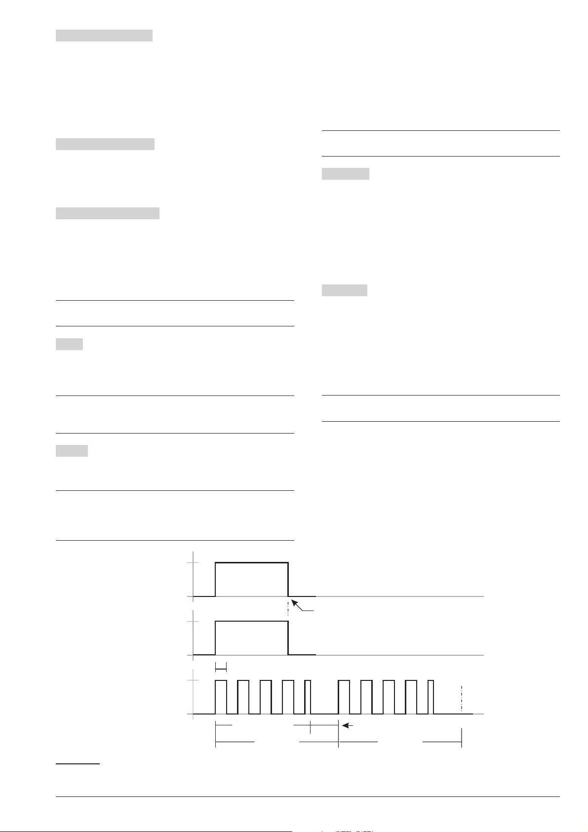
Monostable-Enabled If this option is disabled (at de
... occurs
... ends
EVENT
... active
... standby
Bistable
OUTPUT
... active
... standby
Monostable
OUTPUT
Half cycle
ON time
OFF time
1 Cycle
st
2 Cycle
nd
the event ends here
fault) the Output is Bistable: it will activate when AT
LEAST ONE of its associated Events occurs, and will
stop when ALL of its associated Events end.
If this option is enabled, the Output is Monostable: it will
activate when AT LEAST ONE of its associated Events
occurs, and will stop when the programmed ON Time
expires (see “ON Time” below).
-
The Output will continue to run the programmed num
ber of Cycles even after the triggering event has been
cleared. During each cycle, the Output will be active for
the programmed ON Time and will restore to standby
for the programmed OFF Time.IfanHalf Cycle has
been programmed, the Output will oscillate in accor
dance with the Half Cycle parameters (during the ON
Time), as shown in Figure 25.
-
-
Monostable-Time ON This is the maximum activation
time of the Output.
Valid entries: 1 through 25 seconds, in 1-second
steps; 1 through 127 minutes, in 1-minute steps.
Default: 3 minutes.
Monostable-Time OFF This is the minimum OFF
Time after restoral of the Output. The Output will be un
able to re-activate until the programmed OFF Time ex
pires.
Valid entries: 1 through 255 seconds, in 1-second
steps;
Default: 6 seconds.
The Monostable-Time On and Monostable-Time
+
Off can be set for Monostable Outputs ONLY.
Timer This option will allow you to associate a Timer
with the Output. The Output can be activated ONLY
when the selected Timer is in the active state (refer to
“Timer”).
When the Timer window expires, the Output will re-
+
store to standby, even if the conditions that generated the event are still present.
The Cycles option can be set for Monostable Out
+
puts only.
Half Cycle If this option is other then zero, the Output
will remain active for the programmed time, return to
standby for the same amount of time, and then reacti
vate, as shown in Figure 25. This option can be used to
-
-
generate visual and audible signals (cause LEDs to
blink or buzzers to sound).
Valid entries: 200 through 1400 milliseconds in 200
milliseconds steps.
If you set 0, the Output will not oscillate.
Partitions If disabled (default) the output is NOT as
signed to the area.
If ENABLED, the output is assigned to the Partition:
the output can be activated/deactivated from the
Ø
keypad ONLY if the PIN and the keypad used share
at least one Partition with those of the output;
Ø the output can be activated/deactivated by telephone
ONLY if the PIN used shares at least one area with
those of the output.
These options are available ONLY for the Re-
+
served outputs.
-
-
-
Cycles Setup the number of cycles the Output mustrun.
Valid entries: 1 to 31 or unlimited cycles.
Default: 1 cycle.
Outputs that have Unlimited set for the Output op
+
tion come back to standby ONLY when you enter/exit
to/from Installer Menu or download the options to
BOSS, therefore this value should be set carefully.
-
Figure 25 The Effect of the Half cycle and Cycle options on Bistable and Monostable Outputs
52 Expandable Hybrid Control Panel
Page 53
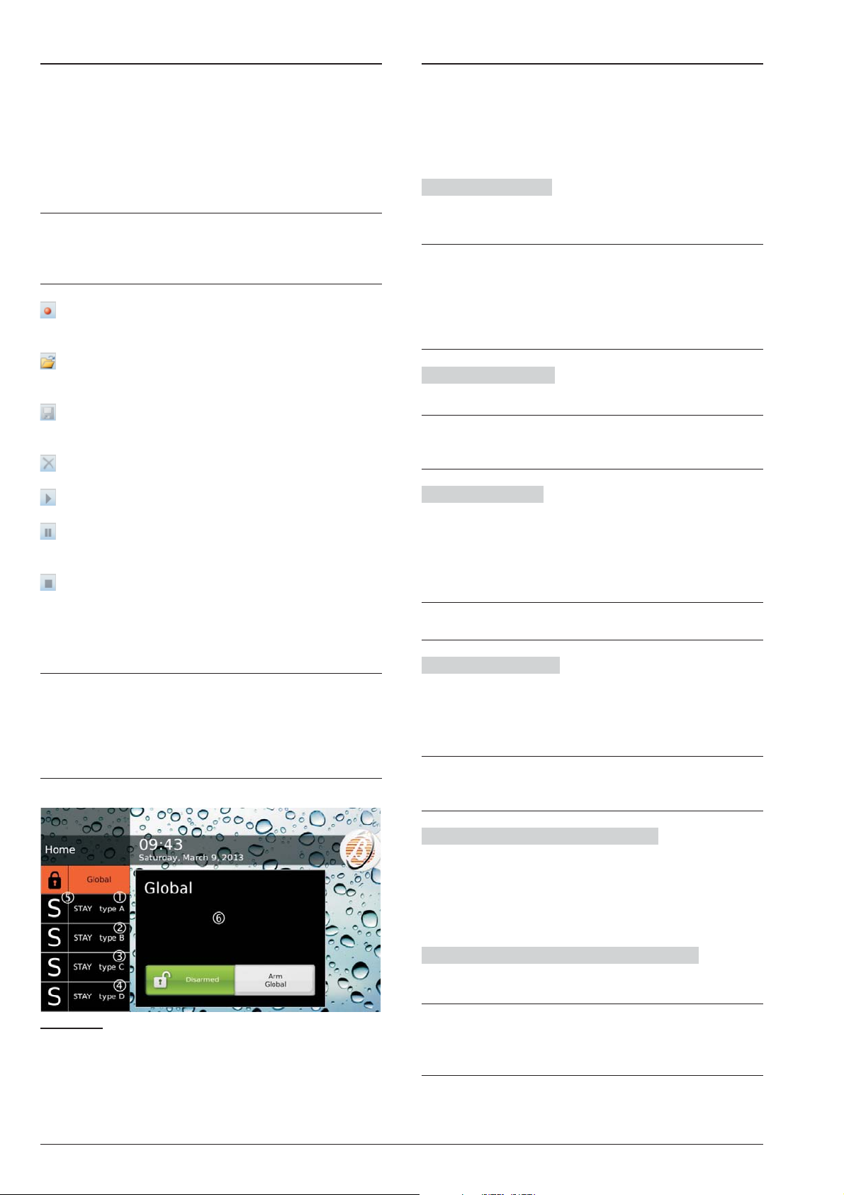
Voice Messages
System Options
This Option Group will allow you to manage voice mes
sages. This Control Panel can store up to 206 mes
sages: 1 Long 12-sec Message; 205 short 6-sec
messages.
You can record the Voice Messages via a microphone
connected to the PC or you can load a prerecorded
messages from thePC resources (hard disk, LAN,etc.)
This Control Panel supports WAVE audio files
+
(.WAV), with different specifications. Possible con
version errors are handled: logged and displayed
to the user.
RECORD button: press to start recording of the
voice message.
LOAD button: click to load a recorded voice mes
sage from the PC resources (hard disk, LAN, etc.).
SAVE button: click to save the voice message on
the PC resources (hard disk, LAN, etc.).
ERASE button: click to delete the voice message.
PLAY button: click to listen to the voice message.
PAUSE button: click to pause playing or recording
of the voice message.
STOP button: click to stop playing or recording of
the voice message.
When recording a message, a counter indicates (in real
time) the time elapsed.
A
In order to comply with the EN50131-1 and
EN50131-3 standards, reserved messages for
alarm, tamper, fault and automatic arming refused
(from No. 2 to No. 9 and No. 13) should NOT be
modified. If there is a Hold-Up Zone, its message
should NOT be changed (No. 14).
-
-
-
-
The System Option Group is to setup the options that
determine the operating mode of the system. You can
find the following Sub-Groups System Group.
General
n
Lock Installer Code If this option is enabled, restoral
of the default settings WILL NOT default the PIN of In
staller Code.
If the option Lock Installer Code is enabled, you
+
CAN’T perform the Hardware Default. In this way
ONLY the Installer (the person that know the In
staller PIN) can perform the default restore via an
LCD Keypad (refer to “Factory Default” in
“KEYPAD OPERATION” section).
BOSS Access Code Enter the Installer PIN.
Default: 0104 (00104 for Grade 3 Control Panels).
If the PIN entered in this option does not match with
+
the one programmed into the Control Panel, you
CAN’T download/upload the options.
User Code Length Enter the number of digits required
for the PIN automatically generated by the control panel
when the Auto PIN Generation option is enabled (refer
to the relative option).
Valid entries: 4(Grade 2 Control Panels ONLY), 5 or 6.
Default: 5.
If the option Auto PIN Generation is disabled, the
+
user can program an 4 to 6 digits PIN.
Auto PIN Generation If this option is enabled, the
Control Panel generates a random PIN when the user
asks for a new PIN. If this option is disable, the user
can enter therequired PIN when he asks for a new PIN.
Default: enabled.
In order to comply with the EN50131-1 and
+
EN50131-3 standards, this option should be
ENABLED.
-
-
Clear System Calls by Master Code If disabled (de
fault), the Main User PIN’s can delete ONLY calls gen
erated by Partition events from the telephone queue.
If ENABLED, the Main User PIN’s may ALSO delete
calls generated by System Events from the telephone
queue.
Clear Calls on Disarming by Master Code If
ENABLED, disarming with a Main User PIN automati
cally cancels calls from the telephone queue.
Depending on the status of the Clear System
+
Figure 26 Arming by the Touch Keypad: labels 1, 2, 3
and 4 can be customised, as explained in the text; the
corresponding Special arming initial letter will be put in
position 5; the description assigned to the arming se
lected will appear in window 6, as explained in the text.
-
Calls by Master Code option, ONLY calls gener
ated by Partiton Events and ALSO those gener
ated by System Events will be deleted.
Default: disabled.
ABSOLUTA PROGRAMMING FROM THE PC 53
-
-
-
-
-
Page 54

Enable Level 4 If this option is enabled, it is possible to
access Level 4 from a keypad connected to the Control
Panel (see “KEYPAD OPERATIONS”).
Default: disabled.
Allow installer access to personal programming
Shows whether the installer is allowed to upload/down
load the user’s PIN’s onto/from BOSS and a USB key
(read “OPERATING YOUR SYSTEM FROM A
KEYPAD>Enable Installer (Teleservice) (2.2)” in the
USER MANUAL).
A Arming Description Insert a text that describes
arming Type A: this text will be shown in the Touch Key
pad when the corresponding arming is selected, as
shown in Figure 26 (6).
Valid entries: up to 128 characters.
Default: empty.
B Arming Description Like “A Arming Description”
but for arming type B.
Valid entries: up to 128 characters.
Default: empty.
-
This is a read-only option.
+
T1 Input or Output Select the functioning mode for
terminal T1 on Main Board: Input or Output.
Default: Input.
T2 Input or Output Select the functioning mode for
terminal T2 on Main Board: Input or Output.
Default: Input.
T3 Input or Output Select the functioning mode for
terminal T3 on Main Board: Input or Output.
Default: Input.
T4 Input or Output Select the functioning mode for
terminal T4 on Main Board: Input or Output.
Default: Input.
A Arming Label Enter the message that the Keypads
should show when Type A Arming takes place, as
shown in Figure 26 (1) for the Touch keypad.
Valid entries: up to 16 characters.
Default: STAY type A.
B Arming Label Enter the message that the Keypads
should show when Type B Arming takes place, as
shown in Figure 26 (2) for the Touch keypad.
Valid entries: up to 16 characters.
Default: STAY type B.
C Arming Label Enter the message that the Keypads
should show when Type C Arming takes place, as
shown in Figure 26 (3) for the Touch keypad.
Valid entries: up to 16 characters.
Default: STAY type C.
C Arming Description Like “A Arming Description”
but for arming type C.
Valid entries: up to 128 characters.
Default: empty.
D Arming Description Like “A Arming Description”
but for arming type D.
Valid entries: up to 128 characters.
Default: empty.
Global Arming Description Like “A Arming Descrip
tion” but for Global arming.
Valid entries: up to 128 characters.
Default: empty.
Squawk Time On Set Squawk (short audible signal)
duration to signal confirmation of arming/disarming or
arming locking (see “USER MANUAL > APPENDIX >
Arming block conditions”), implemented via the Command Zone or Wireless Key: one Squawk confirms
arming/disarming; two Squawks indicate that arming
was refused.
Squawk Time Off Set the pause between the two
squawks of inhibited arming signalling.
Output for Squawk Select the Control panel output
connected to the siren that will play the squawk.
Bypass Tamper on Zone If this option is enabled, by
passed Zones will not generate Tamper Alarms.
Enable Auto Arming If this option is enabled the Con
trol Panel can perform the auto arming set in the Arm
ing Schedule option group.
-
-
-
-
D Arming Label Enter the message that the Keypads
should show when Type D Arming takes place, as
shown in Figure 26 (4) for the Touch keypad.
Valid entries: up to 16 characters.
Default: STAY type D.
LCD Keypad Standby Page Enter the message that
the LCD Keypads should show in standby status.
Valid entries: up to 16 characters.
Default: BENTEL ABSOLUTA.
Mains Fault Timeout This option will allow you to set
the amount of time that must expire before the Warning
mains failure event occurs.
Valid entries: 0 through 250 minutes, in 1-minute steps
Default: 0 minutes.
A
In order to comply with the EN50131-1, EN50131
and EN50131-3-6 standards, this option should not
be more than 1 minute.
54 Expandable Hybrid Control Panel
Page 55

Panel ID Code Enter the ID Code assigned to the con
trol Panel during the Wizard Setup.
The Panel ID Code set in BOSS must match with the
+
one set during the Wizard Setup of the Control Panel
to Downloading/Uploading by means an USB key.
Keypad Language Selection Select the language for
the keypad messages.
Bell Cutoff Set the duration of the Zone Alarm event
when the Real Time option is DISABLED (see Zones
options). This option also determines the duration of
partition Alarm.
Valid entries: 5 through 15.000 seconds in1-second steps.
Default: 180 seconds (3 minutes).
Since an alarm is detected, before the end of this
+
time, it is no possible to activate again the siren.
The siren will be activated only for a new event will
occur after this time.
Country Selection for Tone Settings This is the same
option as in the Advanced Call sub-group.
If your country is not in the list or if you have prob
+
lems with the phone line, select Custom and set
the parameters manually in the Advanced Call
sub-group.
-
-
Dialer Priority Every event may perform the following
actions:
Speaker: Voice Message on AS100 Audio Station.
Ø
Digital/Vocal calls: Digital or Voice calls on the tele
Ø
phone landline (PSTN) or on the GSM line (if the
ABS-GSM Module is installed).
SMS: sending an SMS by GSM (if the ABS-GSM
Ø
Module is installed);
Receiver Event, event reporting via GPRS and/or IP
Ø
to the Sur-Gard SYSTEM I / II / III receivers;
Push Event, event reporting via e-mail and/or the
Ø
ABSOLUTA app.
Choose the order of priority for actions:
Speaker - Digital/Voice Calls - SMS - Receiver Event
Ø
- Push Event;
Speaker - SMS - Digital/Voice Calls - Receiver Event
Ø
- Push Event;
Speaker - Receiver Event - Digital/Voice Calls - SMS
Ø
- Push Event;
Speaker - Receiver Event - SMS - Digital/Voice Calls
Ø
- Push Event;
Speaker - Digital/Voice Calls - Receiver Event - SMS
Ø
- Push Event;
Speaker - SMS - Receiver Event - Digital/Voice Calls
Ø
- Push Event.
Default: Speaker - SMS - Digital/Voice Calls - Receiver
Event - Push Event.
-
Ignore Log Limit If NO, the logger records maximum
5 equal events during an arming period.
If YES, there is no limit to the equal events recorded in
the logger.
Default: No.
A
In order to comply with the EN50131-1 and
EN50131-3 standards, this option should be NO.
Panel AS Tamper In this option you can enable the
functioning of the external siren about the Tamper. You
can choose between: AS Balanced Tamper and Ex
ternal siren tamper.
Default: External siren tamper.
A
In order to comply with the EN50131-1 and
EN50131-3 standards, this option should be Exter
nal siren tamper.
Supervised Siren If enabled, the Control Panel can
detect and signal short circuits and interruption on the
terminal +A line.
Terminal +A must be wired as indicated in
+
“INSTALLATION>Connecting Signalling De
vices>Supervised Outputs”.
Hardware Type This is an read-only option shows the
type of electronic card in the control panel:
Ø Standard Audio Quality;
Ø Enhanced Audio Quality.
Reset alarm/tamper memory on arming (Master code - keys)
If enabled, the alarm and tamper events stored during an
arming period will be deleted the next time the system is
armed using a Master Code, a Normal Code or a Key.
Default: enabled.
ONLY the memory relating to the common Partitions
-
-
-
+
with PIN/Key and Keypad/Reader will be deleted.
If the Don’t allow Master user to clear tamper mem
+
ory (T014) option is enabled alarm notifications
ONLY will be cleared.
Don’t allow Master user to clear tamper memory (T014)
If this optionis enabled the user cannot clear the tamper
memory.
Default: disabled.
3
This option is ENABLED and locked (cannot be
changed) on Grade 3 Control Panels.
-
ABSOLUTA PROGRAMMING FROM THE PC 55
Page 56

Disable code if duplicated PIN If the Auto PIN Gen
eration option is disabled it may transpire that when a new
PIN is programmed it is the same as another PIN in the
system; in this case system security will be compromised.
If this option is ENABLED the used PIN is disabled and
can only be re-enabled by a Master PIN enabled in the
same Partitions as the used PIN.
The duplicated PIN is flagged by:
the Duplicated PIN fault;
Ø
the Duplicated and Discovered PIN event.
Ø
The used PIN and the PIN which detected it are
+
stored in the events log.
-
Surveillance Maintenance interval Set the time that
must elapse between a Surveillance Maintenance on
Panel event and the next.
Valid entries: 0 through 65,535 minutes.
Daylight saving time/Daylight saving time - restored
If required, change the date and hour for Summer time
begins/ends:
the Panel moves 1 hour forward its clock, on date
Ø
and time set for the Daylight saving time options;
the Panel moves 1 hour back its clock, on date and
Ø
time set for the Daylight saving time - restored op
tions;
-
This option is disabled and locked if the Auto PIN
+
Generation option is ENABLED.
Default: disabled.
Receiver Channel Prioity Select the channel for
transmitting events to the Sur-Gard SYSTEM I, II or III
receivers, as outlined below.
GPRS Only: the GPRS channel ONLY will be used.
Ø
IP Only: the IP channel ONLY will be used.
Ø
GPRS Primary, IP Backup: the IP channel will be
Ø
used in the event of a GPRS channel failure.
IP Primary, GPRS Backup: the GPRS channel will
Ø
be used in the event of an IP channel failure.
Default: IP Primary, GPRS Backup.
n Time Options
Date / Time Set Date and the Time of the Control
Panel.
Date and Time can be programmed also by keypad.
+
Periodic Test Transmission time Set the date and
the time of the first Periodic Test.
Periodic Test Transmission interval Set the time
that must elapse between a Periodic Test and the next.
Valid entries: 0 through 65,535 minutes.
A
In order to comply with the EN50136-2-1 standards,
the option Periodic Test Transmission should
ENABLED and the Periodic Test Transmission
interval MUST NOT be more then 1,500 minutes
(25 hours) for Grade 2 Control Panels with ATS2
and 180 s for Grade 3 Control Panels and ATS5.
The system will signal Automatic Changeover by:
switching ON the G LED.
Ø
The G LED signals several different types of Trouble
+
events. If signalling is due to the Standard time/Sum
mer time changeover, the Keypad (in View Trouble
Mode) will show the summer time message.
Default: the Panel moves its clock 1 hour forward at 2
AM of the last March’s Sunday and 1 hour back at 3 AM
of the last October’s Sunday, until 2030.
Received Call
n
Number of Rings Set the number of rings the Control
panel must allow before answering an incoming call.
If the Double call option is enabled, the Number of
+
Rings will be ignored (refer to “Double call”below).
Double Call Enable This option will allow the Control
Panel to share the telephone line with another answering device (answering machine, fax, etc.). Under normal circumstances, the device which allows the least
number of rings will answer any incoming calls. However, if this option is Enabled, the Control panel will
override the other answering device when it recognizes
the Double Call sequence.
Double Call sequence: the caller must allow no more than
2 rings, then hang up and callback within 60 seconds. The
Control panelwill answer on the first ring ofthe second call.
The other answering device must be programmed
+
to answer after 3 or more rings.
n
Phone Options
-
Installer Maintenance Time Set the date and the time
of the first Installer Maintenance event.
Installer Maintenance Interval Set the time that must
elapse between a Installer Maintenance event and the
next.
Valid entries: 0 through 65,535 minutes.
Surveillance Maintenance Time Set the date and the
time of the first Surveillance Maintenance on Panel event.
Call Confirmation If this option is enabled, the Con
trol Panel willnot consider a call successful until the call
receiver presses the star key on the telephone keypad,
in order to generate a feedback signal.
Default: Enabled.
If this option is enabled, you should include a re
+
quest for the feed back signal (press star) in the
message.
56 Expandable Hybrid Control Panel
-
-
Page 57

Call attempts Set the maximum number of Call at
tempts for each Telephone Number.
You have the following preset, unmodifiable, delays be
tween call attempts:
approx. 10 s between attempts to digital numbers;
Ø
approx. 25 s between attempts to different vocal numbers;
Ø
approx. 75 s between attempts to the same vocal number.
Ø
Valid entries: 1to99.Default: 4.
In order to comply with the EN50136-2-3 and
A
EN50136-2-4 standards, the Call attempts option
MUST NOT be less then 2 and more then 4.
Voice in line If this option is ENABLED, the Voice
message will be played after detection of a voice re
sponse. If the Control Panel does not detect a voice re
sponse before the Wait voice timeout ends, it will
hang-up and generate a Dialler action failed event.
Default: Enabled.
Wait voice timeout Set the pause after dialling. If the
Control Panel does not detect a voice answer before
the Wait voice timeout ends, it will hang-up and gener
ate a Dialler action failed event.
The Wait voice timeout applies to the Voice on
+
Line option.
Valid entries: 0 through 240 seconds, in 1 second steps.
Default: 30 seconds.
Transmission Delay Enabled If this option is
ENABLED, the Voice message will be played when the
programmed Wait after select expires.
If both Voice in line and Transmission Delay options
are DISABLED, the Voice message will be played after
dialling.
All calls that comply with the programmed Send
+
Message After conditions will be considered Suc
cessful. However, only the Voice in Line option
ensures a proper response to calls, therefore, if
you disable this option or enable the Transmis
sion Delay option, you should also enable Call
Confirmation option.
-
-
-
-
-
-
-
Audio session timeout Set the two way audio ses
sion time.
Valid entries: 0 through 240 s (4 minutes), in 1-s steps.
Default: 30 seconds.
Line check If this option is ENABLED, the Control
Panel will supervise the telephone line.
Default: Disabled.
In order to comply with the EN50131-1 and
A
EN50131-3 standards, this option must be ENABLED
The system will signal “Line down” (i.e. voltage on the
L.E. terminals less than 3 V) by:
turning ON the G
Ø
an X (blinking) above the i icon;
Ø
generating the Telephone line trouble event.
Ø
The Control Panel will signal “Line restoral” (voltage on
the L.E. terminals more than 3 V for the programmed
Pstn Line Restore) by:
turning OFF the GLED (i.e. unlessthere are other faults);
Ø
clearing the Trouble signal;
Ø
terminating the Telephone line trouble event.
Ø
This option must be disabled when the Control Panel is
not connected to a telephone line, otherwise, the Tele
phone line trouble event will be signalled persistently.
Tone check If this option is ENABLED, the Control
Panel will check for the dialling tone before dialling. If
the dialling tone is not detected during 30 seconds, the
Control Panel will hang-up and retry.
Don’t Check Incoming Call If the Control Panel
makes a call, and this option is disabled, the control
panel checks if there are incoming calls before dialling
the number. In this case, wait.
Default: Enabled.
Pstn Line Restoral Time This option will allow you to
setup the time the telephone line voltage must be over 3
V so the Control Panel will signal “Line restoral” (refer to
“Line check”).
7
LED;
-
-
Voice Message Transmission Delay Set the pause
between the end of dialling and the Voice Message an
nouncement.
The Voice Message Transmission Delay applies
+
to the Transmission Delay Enabled option.
Valid entries: 0 through 240 seconds, in1-second steps.
Default: 30 seconds.
Repetition Set the number of times the Control Panel
must repeat the Voice Message.
Valid entries: 1 through 99.
Default: 3.
A
In order to comply with the EN50136-2-4 standards,
the Repetition option MUST NOT be more then 8.
7 The G LED signals several different types of Trouble events. If the signal is due to telephone line trouble, the
Keypad (in View Trouble Mode) will show the Tel.Lin.Failure message.
-
Answering machine If this option is ENABLED (fac
tory setting) the Control Panel will respond to thecalls ar
riving at the PSTN and/or GSM number (see Answering
Machine Enabled Channels) after the programmed
Number of Rings (see the Received Call options sub
group): at this point, if an enabled User PIN is known
(see DTMF in the Codes and Keys > User options
group) the Control Panel can be managed from the call
ing telephone (see “TELEPHONE OPERATIONS” in the
User Manual for further information).
The Answering Machine function can be En
+
abled/Disabled also by the User (refer to “Enable/Dis
able Answering Machine” in the USER MANUAL).
ABSOLUTA PROGRAMMING FROM THE PC 57
-
-
-
-
-
-
Page 58

Answering Machine Enabled Channels Select the
channel used by the Control Panel to answer the phone
calls:
Only PSTN, the Control Panel will answer ONLY
Ø
calls made to its PSTN phone number;
Only GSM, the Control Panel will answer ONLY calls
Ø
made to its GSM phone number;
PSTN and GSM, the Control Panel will answer calls
Ø
made to both its PSTN and its GSM phone number.
Default: Only PSTN.
The Present and Enabled options in the GSM op
+
tion group must be ENABLED to set this option.
Vocal Guide If this option is enabled (default), a vocal
guide will support the user in the remotely control panel
management via a telephone that support the DTMF
tones (refer to “OPERATING THE SYSTEM FROM A
TELEPHONE” on the User Manual for further informa
tion). After listening to the welcome message, will be
played the following messages.
n.159: Welcome. Press pound.
Ø
n.160: Enter code followed by pound.
Ø
n.161: Goodbye. Please hang-up.
Ø
n.162: Alarm call in stand-by. Please hang-up.
Ø
n.163 (Menu 1): Press one for vocal functions.
Ø
n.173 (Sub Menu 1/1): Press one to switch between
Ø
talking and audio verification.
Ø n.174 (Sub Menu 1/2): Press two for two-way call.
Ø n.175 (Sub Menu 1/4): Press four to reduce audio
verification sensitivity.
Ø n.176 (Sub Menu 1/5): Press five for standard audio
verification sensitivity.
Ø n.177 (Sub Menu 1/6): Press six to increase audio
verification sensitivity.
Ø n.164 (Menu 2):Press two for zone or partition status.
Ø n.178 (Sub Menu 2/1): Press one then enter three
digit partition ID.
Ø
n.179 (Sub Menu 2/2): Press two then enter three
digit zone ID.
Ø
n.165 (Menu 3): Press three for output activation.
Ø
n.180 (Sub Menu 3/1): Enter two digit output ID then
press one for activation.
Ø
n.181 (Sub Menu 3/0): Enter two digit output ID then
press zero for deactivation.
Ø
n.166 (Menu 4): Press four to arm disarm panel.
Ø
n.182 (Sub Menu 4/1): Press one to arm away.
Ø
n.183 (Sub Menu 4/2): Press two to disarm.
Ø
n.184 (Sub Menu4/3): Press three to arm stay type A.
Ø
n.185 (Sub Menu4/4): Press four to arm stay typeB.
Ø
n.186 (Sub Menu4/5): Press five to arm stay type C.
Ø
n.187 (Sub Menu4/6): Press six to arm stay type D.
Ø
n.167 (Menu 5): Press five to arm disarm partitions.
Ø
n.188 (Sub Menu 5/1): Enter two digit partition ID
then press one to arm away.
Ø
n.189 (Sub Menu 5/2): Enter two digit partition ID
then press two to disarm.
Ø
n.190 (Sub Menu 5/3): enter two digit partition ID
then press three to arm stay A.
Ø
n.191 (Sub Menu 5/4): Enter two digit partition ID
then press four to arm stay B.
Ø
n.168 (Menu 6):press six to enable disable installer.
Ø
n.192 (Sub Menu 6/1): Press one to enable installer.
n.193 (Sub Menu6/0): Press zero to disable installer.
Ø
n.169 (Menu 7): Press seven to clear call queue.
Ø
n.170 (Mewhen a voice call is received from the Con
Ø
trol Panelnu 8): Press eight to reset alarms.
n.171 (Menu 9): Press nine to disable code.
Ø
n.172 (Menu star): Press star to end call, pound for
Ø
main menu.
Messages from the No 159, to No. 193 of the Vocal Guide
have already recorded. The instructions of the recorded
vocal messages, and some examples of typical mes
-
-
sages can be recorded by the installer.
If this option is disabled, the Control panel anyway
+
answer with voice messages to the status requests.
Default: enabled.
DTMF Control If this option is enabled, the user can
remotely manage the control panel, when a voice call is
received from the Control Panel, via a telephone that
support the DTMF tones (refer to “OPERATING THE
SYSTEM FROM A TELEPHONE” on the User Manual
for further information).
Default: Enabled.
When the Control Panel is called, remote manage
+
ment via a DTMF telephone is always possible if a
PIN enabled for this purpose is known.
Adjust the Speaker Volume and Microphone Vol-
+
ume on the GSM module (see the GSM option
group) to resolve any problems in managing the
control panel through the DTMF tones via the GSM.
Disable Siren for Audio Session If during a audio
session (listen-in and/or two-way Talk) and the siren is active, if this option is enabled (Yes), the siren will switch off.
Default: No.
n
Advanced Call Options
Country Selection for tone setting Select the coun
try for the tone setting.
If the Tone check option is enabled (see Phone op
tions) in this menu it is necessary to select the country
for the Tone setting: the values of the options Fre
quency Tone, Continuous, Tone Check, Tones
1-On, Tones 1-Off, Tones 2-On, Tones 2-Off, Tones
3-On, Tones 3-Off for the Dial Tone, for the Congestion
Tone and the Busy Tone will be automatically
determined.
If a country is not on the list it is necessary to select
+
Custom and set the options listed above.
-
-
-
-
-
-
58 Expandable Hybrid Control Panel
Page 59

EN50131
n
Events and Actions
In order to comply with the EN50131 Standards,
A
ALL the following options must be ENABLED.
Refuse arming on incomplete exit condition It is
possible that the Control Panel is ready for arming also
whit open zones if these zones are programmed as Exit
Delay.
If this option is ENABLED, the Partitions are NOT
armed if there are zone still open at the end of the Exit
Delay.
Refuse arming on keyfob If enabled, it is NOT possi
ble to arm the Partitions using the keyfob in the pres
ence of some of the block conditions (see “USER
MANUAL > APPENDIX> Arming block conditions”).
Apply EN50131 to Scheduler If enabled, it is NOT
possible to arm the Partitions using the Scheduler in the
presence of some of the block conditions (see “USER
MANUAL > APPENDIX > Arming block conditions”).
Refused arming on Command Zones If enabled, it
is NOT possible to arm the Partitions using the Com
mand Zones in the presence of some of the block condi
tions (see “USER MANUAL > APPENDIX > Arming
block conditions”).
The Events and Actions options group determines
Control Panel operation as outlined below.
The left side of the window shows the categories of
events recognised by the Control Panel: enable the
Only Categories With Data option to display ONLY the
categories that have at least one programmed action.
The centre of the window shows the events for the se
lected category on the left-hand side of the window, and
shows the associated actions for each event: enable
the Only Items with Data option to display ONLY the
events that have at least one programmed action.
-
-
-
-
The table is displayed in a compact format; for each
event the following is displayed:
Nothing, if the event is NOT associated with any ac
Ø
tion or;
Outputs, if the event activates at least one Output;
Ø
AS100, if the event reproduces Voice Messages at
Ø
the Audio Station;
CALLS, if the event sends Voice Messages;
Ø
SMS, if the event sends SMS messages;
Ø
Central Station Event, if the event is transmitted to
Ø
a Central Station.
Double click on the [+] symbol next to the action header
to display the options. Double click on the [–] symbol to
hide the options.
-
-
Apply EN50131 to SMS Arming If enabled, it is NOT
possible to arm the Partitions via SMS in the presence
of some of the block conditions (see “USER MANUAL >
APPENDIX > Arming block conditions”).
3
This option is ENABLED and locked (cannot be
changed) on Grade 3 Control Panels.
EN50131 Wireless Delinquency If ENABLED, the
Control Panel expects a signal from each enrolled wire
less detector, within 15 minutes from when the last one
was received. If it does not arrive a ZONE FAULT is gen
erated for the zone covered by that detector.
Only the Wireless Zones that have the Supervi
+
sion option ENABLED are checked (see the Zone
options group).
This option is similar to the Supervision option in
+
the Zone options group, except that the latter gen
erates a tamper event and the Supervision Pe
riod can be programmed (see the Configuration
> Wireless Module options group).
n
Installer
The information entered in these options will be dis
played on the Touch Keypad (see “USER MANUAL >
OPERATIONS FROM TOUCH KEYPAD > Info > In
staller”).
n OUTPUTS ACTIVATION
This subgroup of options is there for setting Output activation by events: up to three outputs for each event can
be selected.
Enabled If disabled (default), the event does NOT activate the outputs.
If ENABLED, when the event occurs, it activates the
-
-
-
-
-
-
-
outputs selected in the options First Output, Second
Output, and Third Output.
First Output\Second Output\Third Output Select
the Outputs that the event must activate when it occurs:
you can set up to three outputs for each event.
A Bistable Output restore to standby status when
+
the event ends.
A Monostable Output restore to standby status
when its ON Time ends.
n
VOCAL ACTIONS/AS100 - CALLS
This subgroup of options is for setting the playing of
Voice Messages due to an event. Up to five Voice Mes
sages can be associated with each event: the first two
are fixed and depend on the event, the other three can
be added for a more detailed description of the event.
The Voice Messages may be played by the loudspeaker
of the AS100 (see the AS100 option) and/or sent to the
programmed telephone numbers (see the Telephone
Enabled and Vocal Numbers). options).
-
3
In order to comply with EN50131 Grade 3 stan
dards, Voice Messages may NOT be used for
alarm notifications.
ABSOLUTA PROGRAMMING FROM THE PC 59
-
Page 60

AS100 If disabled (default), the event DOES NOT play
the Voice Messages.
If ENABLED, the event plays the Voice Messages se
lected in the options First/Second Message, Third
Message, Fourth Message and Fifth Message.
First/Second Message Displays the word AUTOMATIC
because the first message is always message no. 1
(RESERVED - Panel Header), whereas the second mes
sage depends on event type, as outlined below (see the
Voice Message options group):
Message no. 2 (RESERVED - Alarm) when an alarm
Ø
event is VERIFIED;
Message no. 3 (RESERVED - Tamper) when a tam
Ø
per event is VERIFIED,
Message no. 4 (RESERVED - Fault) when a fault
Ø
event is VERIFIED,
Message no. 5 (RESERVED - Restoral Alarm)
Ø
when an alarm event ENDS,
Message no. 6 (RESERVED - Restoral Tamper)
Ø
when a tamper event ENDS,
Message no. 7 (RESERVED - Restoral Fault) when
Ø
a Fault Event ENDS,
Message no. 8 (RESERVED - Generic) when a ge
Ø
neric event is VERIFIED.
Message no. 9 (RESERVED - Restoral Generic)
Ø
when a generic event ENDS;
The first message is ONLY reproduced via tele-
+
phone and NOT on the AS100.
Third Message, Fourth Message and Fifth Message
Select the Voice Messages that the event must play when
it occurs in addition to the first and second message.
Voice Messages for the event restore will be
+
played ONLY if the Restore option is enabled (see
later in this section).
Tlephone Enabled If disabled the event does NOT
play voice messages by telephone. If ENABLED the
event PLAYS voice messages for selected numbers
(see Vocal Numbers).
Default: see Table 9.
Call All If this option is ENABLED (default), the Control
Panel will call ALL the phone numbers for the event
-
-
-
-
(see Vocal Numbers).
If this option is disabled, the Control Panel will call the
phone numbers for the event (see Vocal Numbers)un
til a call ends successfully: the other event’s numbers
will NOT be called.
Vocal Numbers8If disabled, the event does NOT play
the Voice Message for the corresponding Telephone
Number. If ENABLED (default), the event PLAYS the
Voice Message for the corresponding Telephone Num
ber (see the Phonebook options group).
The Control Panel will call either ALL programmed
+
Phone numbers or the programmed Phone num
bers until one call is successful, depending on the
options Call All.
SMS
n
This sub-group of options involves settings for SMS
messages that must be sent by the events.
In order to comply with EN50131 Grade 3 stan
3
dards, SMS Messages may NOT be used for alarm
notifications.
To use this function the ABS-GSM GSM Module
+
must be installed and programmed as outlined in
the “GSM” section.
SMS Enabled9If disabled (default), the event does
NOT send SMS.
If ENABLED, the event sends an SMS messages to the
numbers selected in the option Vocal Numbers. When
the event OCCURS, the SMS message consists of the
following parts (Seethe SMS Messages option group):
Ø SMS n. 1 (Panel Header);
Ø
SMS n. 2 (Alarm) for alarms or
SMS n. 3 (Tamper) for tampers or
SMS n. 4 (Fault) for troubles or
SMS n. 8 (Generic) for other events;
Ø
the SMS message selected in the option SMS Text;
Ø
time and date of the event
10
.
-
-
-
-
Restore If disabled the event does NOT play voice
messages by telephone when it ends. If ENABLED (de
fault), when the event ends the selected Voice Mes
sages are PLAYED.
8 This column ONLY shows the Voice Dialler telephone numbers that are NOT empty i.e. are made up of at least one
digit (see Number and Type in the Phonebook options group). This column is NOT displayed if there is no
telephone number with these characteristics.
9 Events that belong to the events group in the Smart Actions options group, which have the All option ENABLED,
have the SMS Enabled and Restore via SMS options ENABLED and locked (cannot be changed), the SMS if
Voice Call Failed option disabled and locked, and the SMS Text option empty and locked (see “Smart Actions” for
further information).
10The time and date of the event are displayed in the format (<hh:mm:ss><space><dd/mm/yy>), where hh = hour,
mm = minutes, ss = seconds, dd = day, mm = month, yy = year; the date format can be changed (see “Date/Time
(2.4)” in the USER MANUAL).
-
-
60 Expandable Hybrid Control Panel
Page 61

Restore via SMS8If ENABLED when the event ENDS,
the control panel send a SMS message, it consists of the fol
lowing parts (see the SMS Messages option group):
SMS n. 1 (Panel Header);
Ø
SMS n. 5 (Restoral Alarm) for alarms or
Ø
SMS n. 6 (Restoral Tamper) for tampers or
SMS n. 7 (Restoral Fault) for troubles or
SMS n. 8 (Restoral Generic) for other events;
the SMS message selected in the option SMS Text;
Ø
time and date of the event
Ø
SMS if Voice Call Failed8If ENABLED, the event
sends the SMS to the programmed numbers (see SMS
> Vocal Numbers) ONLY if the voice calls fail.
Default: disabled.
SMS Text8Select the SMS message that the event
should send (see the SMS Messages option group).
Default: none.
Events that belong to the events group in the
+
Smart Actions options group, which have the
Only enabled in Events and Actions option
ENABLED, have this option empty and locked (see
“Smart Actions” for further information).
Vocal Numbers7If disabled, the event does NOT send
an SMS to the respective Telephone Number.
If ENABLED (default), the event sends the programmed
SMS message to the respective Telephone Number
(See the Phonebook option group).
9
.
Digital Numbers If disabled, the control Panel does
-
NOT sendthe event to the respective Telephone Number.
If ENABLED (default), the Control Panel sends the
event to the respective Telephone Number (See the
Phonebook option group).
This column ONLY shows the Digital Number
+
telephone numbers that are NOT empty i.e. are
made up of at least one digit (see Number and
Type in the Phonebook options group). This col
umn is NOT displayed if there is no telephone num
ber with these characteristics.
Receiver If enabled, the control panel transmits the
event via GPRS (the GSM module is required) and/or
via IP (the IP module is required) to a Sur-Gard
SYSTEM I, II o III receiver, as configured in the GSM
and IP option groups on the basis of the Receiver
Channel Priority option setting (see the System Op
tions > General options group).
Default: Disabled.
The Receiver is disabled when the option Re
+
ceiver for Digital Call Failed is enabled.
Send Restore Over receiver If disabled, the event
does NOT send codes, via GPRS and via IP, when it
ends.
If ENABLED (default), when the event ends, it sends
the programmed codes via GPRS and/or IP (see Con-
tact ID and Restore SIA Identifier).
-
-
-
-
n CENTRAL STATION ACTIONS
The options described below are for reporting Events in
digital format to the Central Stations via PSTN, GSM,
GPRS and IP.
3
In order to comply with EN50131 Grade 3 standards, ONLY use the ABS-IP IP Module to report
alarms: the integrated PTSN communicator and the
ABS-GSM GSM/GPRS Module CANNOT be used.
Telephone Enabled If this option is ENABLED the
event will be sent via PSTN/GSM to the numbers se
lected in the Digital Numbers option.
Default: see Table 9.
Restore If disabled, the event does NOT send codes,
via PSTN/GSM, when it ends.
If ENABLED (default), when the event ends, it sends
the programmed codes via PSTN/GSM (see Contact
ID and Restore SIA Identifier).
Call All If this option is ENABLED (default), the Control
Panel will call ALL the phone numbers for the event
(see Digital Numbers).
If this option is disabled, the Control Panel will call the
phone numbers for the event (see Digital Numbers)
until a call ends successfully: the other event’s numbers
will NOT be called.
Receiver for Digital Call Failed If enabled, the control panel sends the event via GPRS and/or via IP,
ONLY if it fails to send it via PSTN/GSM.
Default: Disabled.
The option Receiver for Digital Call Failed is dis
+
abled when the Receiver option is enabled.
Digital Call for Receiver Failed If enabled, the con
trol panel will send the event via PSTN/GSM when it
-
fails to send to the receiver via GPRS/IP.
Default: disabled.
The Digital Call for Receiver Failed option is
+
blocked if the Receiver option is disabled or if the
Receiver for Digital Call Failed option is enabled.
Contact ID Enter the Contact ID Reporting Code for
the event: the control panel sends the code, preceded
by the digit 1 when the event OCCURS and by the digit
3 when the event ENDS.
The control panel sends the Contact ID reporting
+
code when the event ends ONLY if the option Re
store is enabled.
Event SIA Identifier Enter the SIA Reporting Code
that the Control Panel must send when the relative
event OCCURS.
-
-
-
ABSOLUTA PROGRAMMING FROM THE PC 61
Page 62

Restore SIA Identifier Enter the SIA Reporting Code
that the Control Panel must send when the relative
event ENDS.
This option is not available for spot events.
+
The control panel sends the SIA reporting code
+
when the event ends ONLY if the option Restore is
enabled.
Remote Command Events
n
In order comply with EN50131 Grade 3 standards,
3
the “Remote Command” Events may NOT be con
trolled by SMS.
These events (Table 15) occur and end when the con
trol panel receives an SMS with the following format:
-
-
00 and 000 mean that the event will be not commu
+
nicated.
Event Description
n
This section describes the conditions that generate,
and terminate each event.
Zone Events Table 10 shows Zone events associated
with Zone alarm and Zone Tamper events.
A Zone event can be restored to standby by:
changing the status (Armed/Disarmed) of a Partition
Ø
the Zone is associated with;
running Alarm Reset from a Keypad (the entered
Ø
User PIN and Keypad must be jointly enabled on a
Partition the Zone is associated with);
running Alarm Stop from the Keypad (the entered
Ø
User PIN and Keypad must be jointly enabled on a
Partition the Zone is associated with);
Using a valid Key on a Reader (both Key and Reader
Ø
must be jointly Enabled on a Partition the Zone is associated with).
Partition Events Table 11 shows the Partition Events.
The Partition Events encase the Zone Events (Fire,
24h, Burglar, etc.). Each Zone event will in turn generate a Partition event (on the Partition theZone is associated with). The Partition event will not terminate until all
the Zone events end.
Partition Events can be restored to standby by:
Ø
changing the Partition status (Armed/Disarmed);
Ø
running Alarm Reset from a Keypad (the entered
User PIN and Keypad must be jointly enabled on the
Partition concerned);
Ø
running Alarm Stop from the Keypad (the entered
User PIN and Keypad must be jointly enabled on the
Partition concerned);
Ø
Using a valid Key on a Reader (both Key and Reader
must be jointly enabled on the Partition concerned).
System Events These are Control Panel-generated
warnings (e.g. Power Failure).
System Events can be restored to standby by:
Ø
running Alarm Reset from a Keypad;
Ø
running Alarm Stop from a Keypad;
Ø
using a Key on a Reader.
Spot Events Spot events, such as Recognized User
PIN on Keypad, are instant. Therefore, any action under
taken on termination would serve no purpose. Therefore:
Ø
Bistable Outputs CANNOT be associated with Spot
Events;
Ø
Dialler and Digital Communicator Actions CANNOT
be associated with restoral of Spot Events.
-
-
#ABS#E#<PIN>#<ON|OFF>#<Command String>#<Text>
PIN: a valid User PIN with the SMS option enabled
Ø
(See the Codes and Keys: User option group).
ON|OFF: ON makes the event occurs; OFF ends the
Ø
event.
Command String: the string entered in the Com
Ø
mand String option (NOT case-sensitive).
Text: an additional text ignored by the control panel
Ø
that can be used by the user to assign a description
to the command’s SMS.
The event occurs or ends ONLY if the PIN and the
+
event share at least one Partition (see Partitions).
The user can disable his own PIN by an SMS mes
+
sage, as described in the USER MANUAL.
The control panel sends confirmationby SMS when the operation has ended successfully (seethe USER MANUAL).
These events can also be controlled using an
+
iPhone or Android smartphone via the ABSOLUTA
App and via an ABSOLUTA M-Touch keypad (see
“USER MANUAL > Touch Keypad Operations >
Scenarios”).
Command String Type the string that needs to be
sent in order for the event occurs or end (NOT
case-sensitive).
The string may consist of up to 16 characters.
Default: empty.
Partitions If disabled, the respective Partition is NOT
assigned to the event.
If ENABLED (default), the respective Partition is as
signed to the event.
-
-
-
62 Expandable Hybrid Control Panel
Page 63
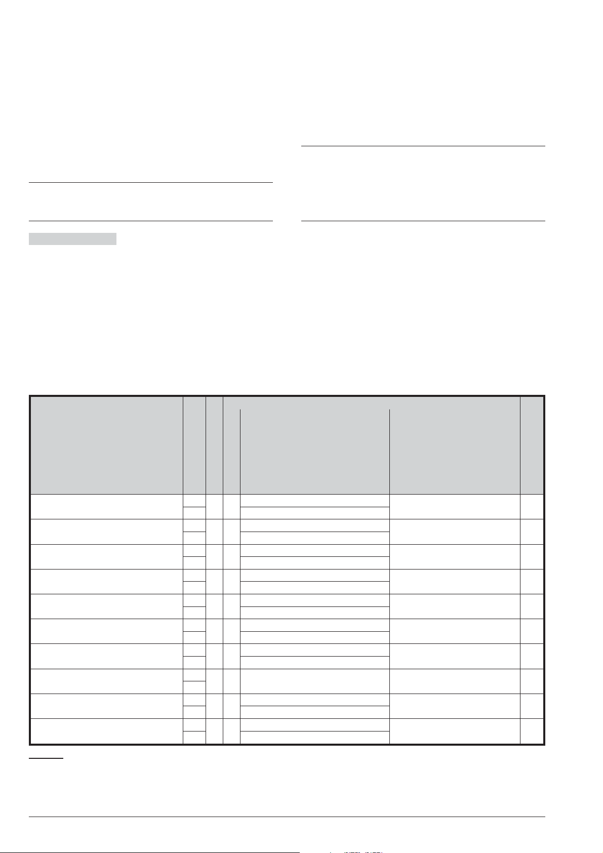
Caller ID over GSM events
n
These events (Table 16) occur when the GSM Module
receives a call from the respective telephone number,
as long as the Caller ID over GSM option for the tele
phone number is ENABLED (see the Phonebook op
tion group).
When the control panel receives the call from the tele
phone number, it hang up after a few rings and per
forms the programmed actions: then the control panel
confirms this by ringing the telephone number, if the
Ringback Enabled option is ENABLED.
The ringback for confirmation may be delayed if there
+
are other calls in the queue or may be lost if the queue
is full or because of problems on the GSM network.
Ringback Enabled If disabled (default), the event will
NOT ring back for confirmation.
If ENABLED, the event will ring back for confirmation.
Default settings
n
The default settings for the Events and Actions Option
Group are made to provide a control panel that can be
-
-
-
-
immediately operative with a minimum setup, as indi
cated on Table 9: the events listed on the EVENTS col
umn, activate the Outputs shown on the FIRST OUTPUT
column and send the Vocal Messages composed by the
Messages shown on the MESSAGE VIA TELEPHONE,
to ALL Voice Dialer numbers in the Phonebook.
In order to comply with the EN50131-1 and
A
EN50131-3 standards, the First Output, Third
Message and Telephone Enabled, about events
on the Table 9, should NOT be modified, only the
Telephone Enabled option relevant to the Gen
eral System Tamper event can be modified.
-
-
-
EVENTS
Zone Alarm (Hold-up) ON
OFF 5 (Alarm Restoral)
General System Alarm ON
OFF 5 (Alarm Restoral)
General System Tamper ON
OFF 6 (Tamper Restoral)
Warning Low Battery on
Wireless Detector
Warning Mains Failure ON
Warning Low Battery ON
Battery Power Trouble ON
System Fault ON
Automatic Arming Refused ON
Tamper on Armed System ON
ON
OFF 7 (Fault Restoral)
OFF 7 (Fault Restoral)
OFF 7 (Fault Restoral)
OFF 7 (Fault Restoral)
OFF
OFF 9 (Restore General Activation)
OFF 6 (Tamper Restoral)
MESSAGE VIA TELEPHONE
STATUS
FIRST OUTPUT
—1
11
21
—1
—1
—1
—1
3— — — No
—1
11
SECOND MESSAGE THIRD MESSAGE
FIRST MESS.
2 (Alarm) 14 (Hold Up in progress)
2 (Alarm)
3 (Tamper)
4 (Fault) 12 (Wireless Batteries)
4 (Fault) 10 (Main AC)
4 (Fault) 11 (Panel Battery)
4 (Fault) 11 (Panel Battery)
8 (General Activation) 13 (Auto arming failed)
3 (Tamper)
— Yes
— Yes
— Yes
Telephone Enabled
Yes
Yes
Yes
Yes
Yes
Yes
Table 9 Default settings for the Events and Actions Option Group: Output nr. 1 is assigned to terminals NC, COM, NO,
+A and +N on the Main Board; Outputs nr. 2 and 3 are, respectively, assigned to terminals O1 and O2 on the Main Board.
Message no. 1 is the Panel Header (see Voice Message options group).
ABSOLUTA PROGRAMMING FROM THE PC 63
Page 64

EVENTS OCCURS WHEN... ENDS WHEN...
Alarm on zone ... the zone detects Alarm conditions
Tamper on zone ... the zone detects Tamper conditions
11
. ... the zone restores to standby status.
11
. ... Tamper conditions are no longer present on
the zone.
Real time of
... the voltage (resistance) on the Zone enters
Zone
the Alarm Range.
... voltage (resistance) on the Zone restores
to Standby Range.
Bypass Zone ... the Zone is bypassed. ... the Zone is restored.
Loss of
Wireless Zone
Device
Low Battery
... the Wireless Detector fails to send a valid
signal during the Supervision Time.
... the Wireless Detector sends a valid signal
during the Supervision Time.
... the battery of the Wireless Detector is low. ... the battery of the Wireless Detector is
charged.
Table 10 Zone Events.
EVENTS OCCURS WHEN... ENDS WHEN...
Generic alarm
on partition
Tamper alarm
on partition
Fire Alarm on
partition
Memory Alarm
on Partition
Alarm Stop on
Partition
Global Arming
Partition
Partial Arming
Partition
Autoarming
Warning
... a Zone (any type) — associated with the Par
tition detects Alarm conditions.
... a Zone — associated with the Partition de
tects Tamper conditions .
... a Zone — associated with the Partition de
tects a Fire Alarm condition.
... the Generic alarm on partition Event oc
... ALL Alarm events generated by Zones — as
sociated with the Partition restore to standby.
... ALL Tamper events generated by Zones —
associated with the Partition restore to standby.
... ALL Fire Alarm events generated by Zones
associated with the Partition restore to standby.
... the Partition Resets.
-
curs.
... a Stop Alarms request is made using a User
PIN enabled for the Partition.
... the Control panel exits the Stop Alarms sta
tus.
... the Partition Arms in Away Mode. ... the Partition Arms in Stay Mode or Stay
Mode with Zero Delay.
... the Partition Arms in Stay Mode or Stay
Mode with Zero Delay.
... there are 10 minutes left before automatic
... the Partition Arms in Away Mode or Disarms.
SPOT EVENT!
arming of the partition.
Partition
Arming Refused
on Partition
Automatic
Arming Refused
on Partition
Disarming
Partition
Schedule on
... a request of Arming on the partition was re-
SPOT EVENT!
fused due to block condition.
... during auto-arming, a Partition's zone is on
SPOT EVENT!
alarm. At default, the Panel must inhibit the
arming without activating the alarm.
... the Partition Disarms. ... the Partition Arms in Away Mode or Stay
Mode or Stay with Zero Delay Mode.
... the scheduler arms the partition. ...the scheduler disarms the partition.
Partition
Entry Time on
Partition
... one of the Entry delay Zones belonging to
the Partition detects Alarm conditions and the
... the Partition Entry Time expires or the Parti
tion Disarms.
Partition is Armed in Stay or Away Mode.
Exit Time on
...the Partition Arms in Stay or Away Mode. ... the Partition Exit Time expires.
Partition
Chime on
Partition
... a Zone with the Chime option belonging to
the Partition detects Alarm conditions when the
SPOT EVENT!
Partition is Disarmed.
Delinquency on
... the Inactivity Time expires. SPOT EVENT!
Partition
Negligence on
... the Negligence Time expires. SPOT EVENT!
Partition
Reset on
Partition
... Alarms Reset is requested using a User PIN
and Keypad jointly enabled for the Partition.
SPOT EVENT!
-
-
-
Table 11 Partition Events
11Zones go into Alarm and Tamper status depending on the settings of the Zone Option Group.
64 Expandable Hybrid Control Panel
Page 65
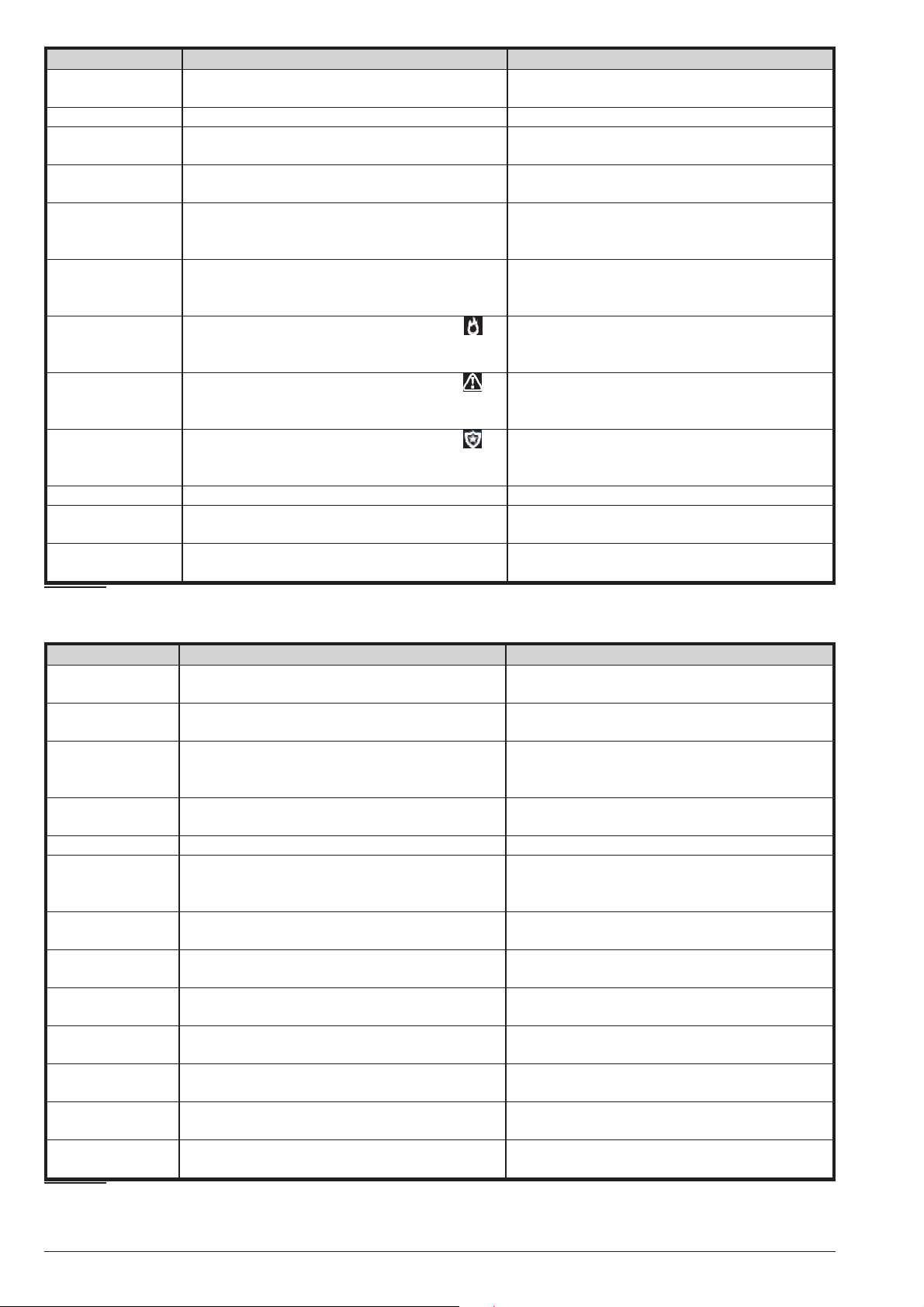
EVENTS OCCURS WHEN... ENDS WHEN...
False Key Event ... a false Key is used on the Reader. ... the false Key has been removed from the
Reader.
Valid Key ... the Key is used on a Reader. ... the Key is removed from the Reader.
Valid Key on Key
Reader
Valid Code ... arming, special arming, disarming or ENTER
Valid Code on
Keypad
Invalid Code on
Keypad
Super Key 1 on
keypad
Super Key 2 on
keypad
Super Key 3 on
keypad
Valid Keyfob ... a button on the valid keyfob has been pressed SPOT EVENT!
Super Key on
Keyfob
Keyfob Low
Battery
Table 12 Key and PIN Events.
... a valid Key is used on the Reader. ... the Key is removed from the Reader.
SPOT EVENT!
key is pressed after entry the User PIN.
... arming, special arming, disarming or
ENTER key is pressed after entry of a VALID
User PIN on the Keypad.
... arming, special arming, disarming or
ENTER key is pressed after entry of an
INVALID User PIN on the Keypad.
... the Key 1 on the LCD Keypad (the Key on
the Touch Keypad) is pressed e hold for 3 (2)
seconds.
... the key 2 on the LCD Keypad (the Key on
the Touch Keypad) is pressed e hold for 3 (2)
seconds.
... the key 3 on the LCD Keypad (the Key on
the Touch Keypad) is pressed e hold for 3 (2)
seconds.
... the button ! of the Wireless key is pressed
and held down for 2 seconds.
... the battery of the keyfob is low. ... the battery is replaced.
SPOT EVENT!
SPOT EVENT!
SPOT EVENT!
SPOT EVENT!
SPOT EVENT!
SPOT EVENT!
EVENTS OCCURS WHEN... ENDS WHEN...
General System
Alarm
General System
Tamper
Warning Low
Battery on
Wireless Detector
Tamper on Main
Service Jumper ... the SERVICE jumper is inserted ... the SERVICE jumper is removed.
Tamper on
External Siren
Fault on
External Siren
Tamper on
Internal Siren
Fault on Internal
Siren
Tamper BPI
Device
Wireless
Receiver Tamper
Warning BPI
peripheral
WLS Receiver
Table 13 System Events (continued on next page).
... a Zone — regardless of its Type and Partition detects Alarm conditions.
... a Zone — regardless of its Partition detects
Tamper conditions.
... the battery of at least one Wireless Detector
is low.
... the Control Panel Tamper switch opens. ... the Tamper switch restores.
Unit
... External Siren Tamper is set for the Panel
AS Tamper option AND the AS terminal is un
balanced.
... the external siren fails. ... ALL the fault conditions on the external siren
... the supervised output is tampered. ... the Output tamper event ends.
... the internal siren fails. ... ALL the fault conditions on the internal siren
... a BPI Device Tamper switch or Wall-Tamper
switch open.
... the Tamper switch or Wall-Tamper Switch of
a Wireless Device is tripped.
... an enrolled BPI peripheral does not respond
to the Control Panel.
... an enrolled Wireless Device does not re
Lost
spond to the Control Panel.
... ALL events generated by the zones of all
Partitions restore to standby.
... ALL Tamper events generated by the zones
of all Partitions restore to standby.
... the last Wireless Detector has closed and
ALL Wireless Sensor batteries are charged.
… External Siren Tamper is set for the Panel
-
AS Tamper option AND the [AS] terminal is bal
anced (grounded with a 10,000 ohm resistor).
restore.
restore.
... all BPI Device Tamper switches and
Wall-Tamper switches restore.
... the Tamper and Wall-Tamper switches of all
Wireless Devices are closed.
... ALL the BPI peripherals respond to the Con
trol Panel.
-
... ALL the enrolled Wireless Devices respond
to the Control Panel.
-
-
ABSOLUTA PROGRAMMING FROM THE PC 65
Page 66

EVENTS OCCURS WHEN... ENDS WHEN...
Warning Fuse ... at least one of the power terminals on the
Main Board (+F, +B, +BPI, RED) is over
loaded.
Warning Mains
Failure
Warning Low
Battery
Battery Power
Trouble
Telephone Line
Trouble
Warning Mains
Failure on
Power Station
Warning Low
Battery on
Power Station
Warning Power
Trouble on
Power Station
Battery not
Connected on
Power Station
Battery Charger
Trouble on
Power Station
Short Circuit
Output 1/2/3 on
Power Station
Battery Charger
Disconnected on
Power Station
Reset on Panel ... Alarms Reset is requested. SPOT EVENT!
Chime on Panel ... a Zone with the Chime Attribute detects
Negligence on
Panel
Delinquency on
Panel
Installer
Maintenance
Balanced
Tamper
Tamper on Main
Unit (Seized)
Wireless Zone
Loss on Panel
...Mains power has been off for the pro
grammed Timeout (refer to "Options").
... Battery voltage drops below 11.4 V. ... Battery voltage is restored to 12.3 V.
... a Battery fails the Dynamic Test (refer to
"Connecting the Power supply" under
"INSTALLING"), or fuse blows.
... the Telephone Line voltage is less than 3 V
for 45 seconds. If the Line check is disabled
(refer to "Phone Options"), the event cannot
be generated.
... the programmed Timeout expires (refer to
"Power stations" under “Configuration”). The
Timeout will start when the Control Panel de
tects failure of the Mains supply — to one of the
BPI Bus Power Supply Stations.
... the Battery Voltage of a BPI Power Supply
Station drops below 11.4V.
... the Battery of a Power Supply Station fails
the Dynamic test or it is disconnected, or the
Power Supply Station polarity inversion fuse
blows.
... the voltage of a Power station battery is below 10.2 V at power up (the battery is exhausted).
... the output voltage of a Power station power
supply module is 0.5 V above or below the preset value.
... the current draw of a Power station output is
over 1.8 A.
... the output voltage of a Power station power
supply module is 0.5 V above the preset value.
Alarm conditions when its Partition is Dis
armed.
... the Negligence Time expires. SPOT EVENT!
... the Inactivity Time expires. SPOT EVENT!
Test ... programmed (see System Options > Time
> Periodic Test Transmission).
... programmed (see System Options > Time
> Installer Maintenance).
... Balanced Tamper is set for the Panel AS
Tamper option AND the AS terminal is unbal
anced.
... the Control Panel wall-tamper switch opens. ...the Wall-Tamper switch restores.
... at least one of the Wireless Detectors of a
Supervised Wireless zone fails to send a valid
signal during the Supervision Time.
... the current drawn by the power terminals on
the Main Board (+F, +B, +BPI, RED) drops be
low the permitted limit.
... Mains power is restored.
-
... Battery meets the Dynamic Test require
ments, and fuse is replaced.
... the Telephone Line voltage is higher than
3 V for 45 seconds.
... Mains power is restored to ALL the BPI Bus
Power Supply Stations.
-
... the Battery voltage of ALL BPI Power Supply
Stations restores to 12.3V.
... the Batteries of ALL the Power Supply Sta
tions are connected and pass the Dynamic test
and ALL the Power Supply Station polarity in
version fuses are replaced.
... the voltage of ALL the Power station batteries rises above 12 V.
... the output voltage of ALL the Power station
power supply modules is 0.5 V above or below
the preset value.
... the current draw of ALL the Power station
outputs is over 1.8 A.
... the output voltage of ALL the Power station
power supply modules is 0.5 V below or equal
to the preset value.
SPOT EVENT!
-
SPOT EVENT!
SPOT EVENT!
... Balanced Tamper is set for the Panel AS
-
Tamper option AND the AS terminal is bal
anced (grounded with a 10,000 ohm resistor).
... ALL Wireless Detectors send valid signals
during the Supervision Time.
-
-
-
-
-
Table 13 System Events (continued on next page).
66 Expandable Hybrid Control Panel
Page 67
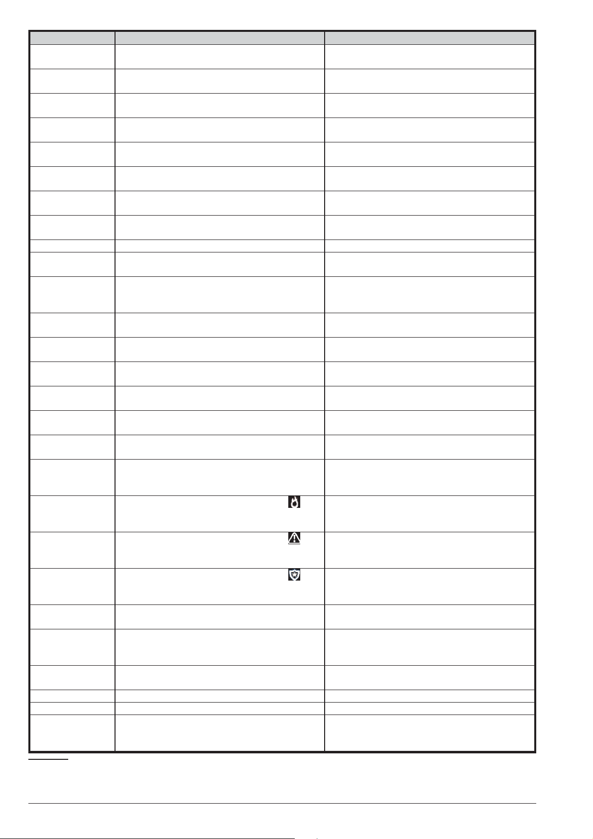
EVENTS OCCURS WHEN... ENDS WHEN...
Zone Alarm on
Panel
Zone Tamper on
Panel
Real Time Zone
on Panel
Zone Bypass on
Panel
Partition Alarm
on Panel
Partition Tamper
on Panel
Partial Arming
on Panel
Global Arming
on Panel
Exit Time on Panel ... a Partition Arms in Stay or Away Mode. ... ALL Partition Exit Dealy expire.
Entry Time on
Panel
Autoarming
Warning on
Panel
Memory Alarm
on Panel
Alarm Stop on
Panel
Valid Key on
Panel
Valid Code on
Panel
Valid Keyfob on
Panel
False Key on
Panel
Invalid Code on
Panel
Super Key 1 on
Panel
Super Key 2 on
Panel
Super Key 3 on
Panel
Keyfob Super
Key on Panel
Surveillance
Maintenance on
Panel
Arm Refused on
Panel
Panel Fault ... a fault happens on the control panel. ... the last fault on the control panel restores.
System Fault ... a fault happens on the system. ... the last fault on the system restores.
Fault/Masking
... a zone detects Alarm conditions. ... ALL zones restore to standby status
... a zone detects Tamper conditions. ... ALL Tamper conditions are no longer pres
ent on the zones.
... the voltage (resistance) on a Zone enters the
Alarm Range
... a Zone is bypassed. ... ALL Zones is restored.
... a Partition goes into Alarm Status. ... ALL Partition restore to Standby Status.
... a Partition goes into Tamper Status. ... ALL Partition restore to Standby Status.
... a Partition Arms in Stay Mode or in Stay
mode with Zero Delay.
... a Partition Arms in Away Mode. ... ALL Partitions Arm in Stay Mode or Stay
... a Entry Delay Zone goes into Alarm Status
when its Partition is Armed in Stay or Away Mode.
... an Auto-Arm Timeout starts. ... ALL Partition Arm or an Overtime Request is
... a Generic alarm on partition Event occurs. ... ALL Partition Reset.
... a Stop Alarm request is made. ... the Control panel exits the Stop Alarms Sta
... a valid Key is used on a Reader. ... ALL the Keys are removed from the Read-
... arming, special arming, disarming or ENTER
key is pressed after entry of a VALID User PIN.
... a button on a valid keyfob has been pressed. SPOT EVENT!
... a false Key is used on a Reader. ... ALL false Keys have been withdrawn from
... arming, special arming, disarming or ENTER
key is pressed after entry of an INVALID User
PIN.
... the key 1 on a LCD Keypad (the Key on a
Touch Keypad) is pressed e hold for 3 (2) sec
onds.
... the key 2 on a LCD Keypad (the Key on a
Touch Keypad) is pressed e hold for 3 (2) sec
onds.
... the key 3 on a LCD Keypad (the Key on a
Touch Keypad) is pressed e hold for 3 (2) sec
onds.
... the button ! of a Wireless key is pressed and
held down for 2 seconds.
... the control Panel clock reaches the time and
date scheduled for the maintenance of the Se
curity Service.
... a request of Arming was refused due to block
condition.
Zone
... a Zone with Triple End of Line Balance de
tects a fault or a Zone Fault Zone has been vi
olated (see " Zones").
... voltage (resistance) on ALL Zones restore to
Standby Range.
... ALL Partitions Arm in Away Mode or Disarm.
mode with zero delay or Disarm.
... ALL Partition Entry Delay expire or ALL Par
titions Disarm.
made.
tus.
ers.
SPOT EVENT!
the Readers.
SPOT EVENT!
SPOT EVENT!
-
SPOT EVENT!
-
SPOT EVENT!
-
SPOT EVENT!
SPOT EVENT!
-
SPOT EVENT!
-
... ALL zones with Triple End of Line Balance
-
and Zone Fault Zones (See "Zones") return to
standby.
-
-
-
Table 13 System Events (continued on next page).
ABSOLUTA PROGRAMMING FROM THE PC 67
Page 68

EVENTS OCCURS WHEN... ENDS WHEN...
Automatic
Arming Refused
Tamper on
Armed System
GSM Absence ... the Present and Enabled options in the
GSM Link Lost ... the GSM network is busy, there is no GSM
GSM Receiver 1
LOST
GSM Receiver 2
LOST
GSM - Cellular
Network Fault
Arming refused
on command
zones
Arming refused
on keyfob
Duplicated and
Discovered PIN
User request
service
IP absence .. .the Present and Enabled options in the IP
IP link lost ... the Present and Enabled options in the IP
IP remote lost ... the Present, Enabled and Absoluta Server
IP receiver 1
IP receiver 2
... during auto-arming, a zone is on alarm. At
default, the Panel must inhibit the arming with
out activating the alarm.
... an Armed Partition's Zone is tampered. ... ALL the Armed Partition's Tampered Zones
GSM options group are ENABLED (and the
control panel has been UNABLE to communi
cate with the GSM Module for 30 seconds).
signal, or there is a problem with the SIMcard.
... the Present and Enabled options and, those
relating to Receiver 1 in the GSM options group
are ENABLED, and the GSM module has prob
lems communicating with the receiver 1.
... the Present and Enabled options and, those
relating to Receiver 2 in the GSM options group
are ENABLED, and the GSM module has prob
lems communicating with the receiver 2.
... the Present and Enabled options in the
GSM options group are ENABLED and the
GSM module has problems communicating
with the GSM network.
... an arming request via a command zone has
been refused due to block conditions.
... an arming request via keyfob has been refused due to block conditions.
... the Auto PIN Generation option is disabled,
the Disable code if duplicated PIN option is
ENABLED (see System Options > General
options group) and a user programs a PIN
used by another user.
... the user requests the Remote Service from a
Keypad (see the USER MANUAL).
options group are ENABLED and the control
panel has been UNABLE to communicate with
the IP Module for 30 seconds.
options group are ENABLED and the IP Mod
ule does NOT see the LAN network.
options in the IP options group are ENABLED
and the IP Module is NOT able to communicate
with the remote server.
... the Present and Enabled options and, those
lost
relating to Receiver 1 in the IP
are ENABLED, and the IP module has prob
lems communicating with the receiver 1.
... the Present and Enabled options and, those
lost
relating to Receiver 2 in the IP options group
are ENABLED, and the IP module has prob
lems communicating with the receiver 2.
options group
SPOT EVENT!
-
return to standby status.
... the Present and Enabled options in the
GSM options group are ENABLED and the
control panel succeeds in communicating with
the GSM Module.
... the GSM network is free, GSM signal is pres
ent, and the GSM Module is communicating
using the SIM card.
... the Present and Enabled options and, those
relating to Receiver 1 in the GSM options group
are ENABLED, and the GSM module is able to
communicate with the receiver 1.
... the Present and Enabled options and, those
relating to Receiver 2 in the GSM options group
are ENABLED, and the GSM module is able to
communicate with the receiver 2.
... the
GSM options group are ENABLED and the
GSM module is able to communicate with the
GSM network.
SPOT EVENT!
SPOT EVENT!
SPOT EVENT!
SPOT EVENT!
option group are ENABLED and the control
panel succeeds in communicating with the IP
Module.
... the Present and Enabled options in the IP
-
option group are ENABLED and the IP Module
sees the LAN network.
... the Present, Enabled and Absoluta Server
options in the IP options group are ENABLED
and the IP Module is ABLE to communicate
with the remote server.
... the Present and Enabled options and, those
relating to Receiver 1 in the IP options group
-
are ENABLED, and the IP module is able to
communicate with the receiver 1.
... the Present and Enabled options and, those
relating to Receiver 2 in the IP options group
-
are ENABLED, and the IP module is able to
communicate with the receiver 2.
Present and Enabled options in the
... the Present and Enabled options in the IP
-
Table 13 System Events (continued on next page).
68 Expandable Hybrid Control Panel
Page 69

EVENTS OCCURS WHEN... ENDS WHEN...
Low Voltage on
Main Power*
Low Voltage on
Output 1*
Low Voltage on
Output 2*
Low Voltage on
Output 3*
Table 13 System Events:this event is ONLY available on Grade 3 Control Panels and Grade 3 Power Stations.
EVENTS OCCURS WHEN... ENDS WHEN...
Dialler Action
Failed on
Telephone
Timer Event ... the timer switches ON. ... the timer switches OFF.
Table 14 Other Events.
... the output voltage of A Power Station is less
than 10.6 V.
... the output voltage of O1 output of A Power
Station is less than 10.6 V.
... the output voltage of O2 output of A Power
Station is less than 10.6 V.
... the output voltage of O3 output of A Power
Station is less than 10.6 V.
... a call, in Dialler mode, to the phone number
failed.
... the output voltage of ALL the Power Stations
is greater than 10.6 V.
... the output voltage of O1 output of ALL Power
Stations is greater than 10.6 V.
... the output voltage of O2 output of ALL Power
Stations is greater than 10.6 V.
... the output voltage of O3 output of ALL Power
Stations is greater than 10.6 V.
SPOT EVENT!
Remote
Command
Table 15 Remote Command events.
Caller ID to Tel. ... the control panel receives a call from the
Table 16 Caller ID over GSM events.
... the control panel receives the following SMS:
#ABS#E#<PIN>#ON#<Command String>#<Text>
(see "Remote Command Events") or the appro
priate command from the ABSOLUTA App or
from an ABSOLUTA M-Touch keypad (see
"USER MANUAL > Touch Keypad Operations
> Scenarios").
telephone number (see "Caller ID over GSM
events").
... the control panel receives the following SMS:
#ABS#E#<PIN>#OFF#<Command String>#<Text>
(see "Remote Command Events") or the appro
priate command from the ABSOLUTA App or
from an ABSOLUTA M-Touch keypad (see
"USER MANUAL > Touch Keypad Operations
> Scenarios").
SPOT EVENT!
-
ABSOLUTA PROGRAMMING FROM THE PC 69
Page 70

Smart Actions
Smart Actions are those which the Control Panel “con
structs” automatically using system information, such
as object labels.
There are three types of Smart Actions:
Smart SMS, to send SMS messages;
Ø
Emails, to send e-mails;
Ø
APP Notification, to send notification to telephones
Ø
with the ABSOLUTA app.
The Smart Actions options group is for programming
Smart Actions as outlined below.
Events Categories Displays the groups of events for
Smart Actions that can be enabled, as outlined in the
following sections.
Smart SMS
n
To create Smart SMS messages BOSS uses the labels
assigned tosystem objects and various fixed strings, as
shown in the first row of Table 17; the square brackets
([]) show the alternatives separated with the pipe sym
bol (|); double quotation marks (“”) show fixed text; curly
brackets () show the various text options described
below.
space is the ‘space’ character.
Ø
Central Header is Message # 1 - Panel in the SMS
Ø
-
-
Messages options group.
String for Reset is the string that is shown if an
Ø
event is reset.
Type of Event is a string relating to event type.
Ø
WHERE is the label assigned to the device used to
Ø
generate the event.
WHO is the label assigned to the subject that caused
Ø
the event.
Partitions is the label assigned to the Partition in
Ø
volved in the event, if an individual Partition is in
volved, or the “Partition:<space>” string followed by
a 16-character string (8 for the ABSOLUTA 16 and
42 control panels) comprising the ‘-’ character for
Partitions NOT involved in the event and the ‘X’ char
acter for Partitions involved in the event (e.g. the
string —X——-X———- means that Partitions 3 and
9 were involved).
Time and Date are the event time and date with the
Ø
format set for the control panel (see “Date/Time
(2.4)” in the USER MANUAL).
-
-
-
<Central Header><space>[<nothing> | <String for Reset><space>]<Type of Event><space>[<nothing> |
Events Category String for Reset Type of Event
Alarm on zone RESTORAL Zone alarm
Tamper on zone RESTORAL Zone tamper
Bypass Zone Zone un-bypassed Zone bypassed
Warning Low Battery on Zone RESTORAL WLS zone bat.low
Loss of Wireless Zone RESTORAL WLS zone lost
Generic alarm on partition RESTORAL Partition alarm
Tamper alarm on partition RESTORAL Zone tamper
Partial Arming Partition RESTORAL Partially Armed
Global Arming Partition RESTORAL ARMED
Disarming Partition RESTORAL DISARMED
Warning low battery on keyfob RESTORAL WLS key bat.low
Arming Refused on Partition N/A Arming refused
Auto Arming Refused on Partition N/A Autoarm refused
Valid Key N/A Valid Key
Valid Code N/A Recognized PIN
Valid Keyfob N/A Valid Key
Real time of Zone RESTORAL N/A
Alarm Stop on Partition RESTORAL Stop alarms
Super Key [1] on keypad N/A Super-key
Super Key [2] on keypad N/A Super-key
Super Key [3] on keypad N/A Super-key
Super Key on Keyfob N/A Super-key
Remote Commands RESTORAL Scenario
Caller ID N/A Event by caller
System - Main AC RESTORAL 220 Vac
System - Mail LOW battery RESTORAL Low battery
System - Periodic event N/A Periodic event
User request service N/A Teleser. request
Table 17 Information to create the Smart SMS messages N/A = Not Applicable; 1) Either GSM, PSTN, APP or SMS
strings; 2) Command String assigned to the Remote Command in the Events and Actions options group.
70 Expandable Hybrid Control Panel
Page 71

Some examples of Smart SMS examples are outlined below:
Home Zone alarm KITCHEN ( first floor ) (10:12:30
Ø
12/24/12);
Home RESTORAL Zone alarm KITCHEN ( first
Ø
floor ) (10:12:30 12/24/12);
Home Zone alarm STAIRS ( partitions:
Ø
X-X——————- );
Home Valid Key DAD READ.MAIN DOOR
Ø
(10:12:30 12/24/12).
Where:
Home is the Central Header;
Ø
Zone alarm and Valid Key are Types of Event;
Ø
RESTORAL is the string to reset the event;
Ø
KITCHEN and STAIRS are the labels of WHO
Ø
caused the event;
first floor is the Partition label involved;
Ø
partitions: X-X——————- are the Partitions in
Ø
volved (no. 1 and 3);
READ.MAIN DOOR is the label of the WHERE ob
Ø
ject that caused the event.
All If this option is ENABLED the Control Panel will
send a Smart SMS upon the verification and reset (for
events that allow reset) of ALL events belonging to the
corresponding group.
Default: Disabled.
This option is disabled and locked if the Only En
+
abled in Events and Actions option is ENABLED.
Only enabled in Events and Actions If this option is
ENABLED the Control Panel will send a Smart SMS
upon the verification and reset (for events that allow re
set) ONLY of events belonging to the corresponding
group that have the SMS Enabled and Restore via
SMS options ENABLED (see the Events and Actions
Options Group).
-
-
Default: disabled.
This option is disabled and locked if the All option is
+
ENABLED.
-
-
As the ABS-GSM supports SMS messages with a
+
maximum length of 160 characters the SMS may
be truncated.
To use this function the ABS-GSM Module must
+
be installed and programmed as outlined in the
“GSM” section.
"-"<space><WHERE><space>"-"<space>] <WHO><space>"("<space><Partitions><space>")"<space>"("<Time and Date>")"
WHERE WHO PARTITION
N/A Zone Label Partition Label or Partition Mask
N/A Zone Label Partition Label or Partition Mask
N/A Zone Label Partition Label or Partition Mask
N/A Zone Label Partition Label or Partition Mask
N/A Zone Label Partition Label or Partition Mask
N/A N/A Partition Label
N/A N/A Partition Label
N/A PIN/Key Label Partition Label
N/A PIN/Key Label Partition Label
N/A PIN/Key Label Partition Label
N/A Wireless key Label N/A
N/A N/A Partition Label
N/A N/A Partition Label
Reader Label Key Label N/A
Keypad Label
N/A Wireless key Label N/A
N/A Zone Label Partition Label or Partition Mask
N/A N/A Partition Label
Super key Label Keypad Label N/A
Super key Label Keypad Label N/A
Super key Label Keypad Label N/A
N/A Wireless key Label N/A
Command String
N/A Tel. Num. Label N/A
N/A N/A N/A
N/A N/A N/A
N/A N/A N/A
N/A PIN Label N/A
1
2
Code Label N/A
PIN Label N/A
This option is not available for the System - Main
+
AC, System - Main LOW battery, System - Peri
odic event - User request service event groups
because these groups consist of only one event.
-
ABSOLUTA PROGRAMMING FROM THE PC 71
Page 72

Emails
n
If this option is ENABLED the Control Panel will send an
12
e-mail
belonging to the corresponding group, to the group of
addresses (up to 4) programmed in the Emails Options
Group, on the basis of the relevant Partition for the
event which has verified.
If the event does not belong to any Partition (System
Events) the e-mail will be sent to a group of specific ad
dresses.
For example, if the Zone 1 Alarm occurs and Zone 1 be
longs to Partitions 1 and 3, the e-mail will be sent to the
addresses defined for Partitions 1 and 3.
The sender of the e-mail will be“[email protected]”.
upon the verification (and reset) of the events
APP Notification
n
If this option is ENABLED the Control Panel will send
notification upon the verification (and reset) of the
events belonging to the corresponding group, to the
telephones that have the ABSOLUTA app installed.
Users with the ABSOLUTA app installed on their
+
telephones must enable them to receive notifica
tion via the relevant option.
User will receive notification of events relating to their
PIN and the Partitions on which it is enabled in addition
-
to System Events (if selected).
The Master User (see User Type in the Codes and
Keys > User Options Group) can disable the function to
receive notification for all telephones registered.
-
The subject ofthe e-mail will have the following format:
<Central Header>":"<space><Type of Event>
Where:
Central Header is Message # 1 - Panel in the SMS
Ø
Messages options group.
Type of Event will be:
Ø
— Alarm, for alarm events,
— Tamper, for tamper events,
— Fault, for fault events,
— Generic, for all other events,
— Restore Alarm, for alarm reset events,
— Restore Tamper, for tamper reset events,
— Restore Fault, for fault reset events,
— Restore Generic,for the reset of all other events.
The body of the e-mail will show the information relating to the event, in the same format as Smart SMS
messages (see “Smart SMS” for further information).
The subject and body of the e-mail may show infor
mation for several events, if they occurred within 20
seconds of the first event.
When users receive notification they can click on the
relevant icon to see event information: information will
have the same format as the Smart SMS messages
(see “Smart SMS” for further information).
To use this function the ABS-IP Module must be in
+
stalled and programmed as outlined in the “IP” section.
Default: disabled.
-
-
To use this function the ABS-IP Module must be in
+
stalled and programmed as outlined in the “IP” section.
Default: Disabled.
12The Control Panel will send the information to a remote server (server.absoluta.info) via the ABS-IP Module with
128-bit AES encryption; the remote server will create a HTML message with the information received to be
forwarded to the programmed e-mail addresses.
-
72 Expandable Hybrid Control Panel
Page 73

Emails
Codes and Keys: User (PINs)
The Emails Options Group is for the definition of the
e-mail addresses to be associated with Partitions and
System Events, for the notification of events via e-mail
(see “Smart Actions > Emails” for further information).
Addresses
n
The E-mail Address Subgroup is for the definition of
e-mail addresses to which events must be sent.
Label Insert a meaningful description for the e-mail ad
dress.
Valid entries: up to 16 alphanumerical characters.
Default: empty.
Address Insert a valid e-mail address.
Valid entries: up to 32 alphanumerical characters.
Default: empty.
Partitions
n
The Partitions Subgroup is for the association of
e-mails, defined in the Addresses Subgroup, with Par
titions.
Label Shows the list of Control Panel Partitions and
the System label for system events.
The User PIN allow the Users to access the system, by
a Keypad, by a DTMF telephone, by SMS and by the
BOSS’s Status Page.
PIN n. 1 CANNOT access the system by phone.
+
Each User PIN can be programmed to control specific
functions and Partitions.
-
-
PIN The PIN is the combination of digits that allows ac
cess to PIN functions. The PIN can be a 4 (Grade 2
Control Panels ONLY), 5 or 6 digit number.
Keypads and User PINs Each Keypad and User PIN
can be programmed to control specific Partitions.
Therefore, the outcome of a command entered at a
Keypad depends on the User PIN and Keypad in use
(commands will affect ONLY the Partitions common to
both the User PIN and Keypad). This dual level of con
trol greatly increases application flexibility, for example,
a PIN can be programmed to control a certain group of
Partitions when entered at one Keypad, and a different
group when entered at another. This feature simplifies
User control, as the same operation will have a different
outcome on different Keypads.
-
-
E-mail Address 1/ E-mail Address 2
E-mail Address 1/ E-mail Address 2 Select the e-mail
addresses where events relating to the corresponding Partitions and System Events must be sent.
Up to 4 e-mail addresses can be selected for each
+
Partition and for System Events.
Valid PIN Event Each time the Control Panel recognizes a Valid PIN, it will generate the Valid PIN Event.
Like all other Control Panel Events, this Event can be assigned to an Output or Telephone Action — regardless of
whether or not the PIN is enabled to request Control
Panel actions. Therefore, an opportune combination of
Events and Outputs will eliminate some of the hitches
linked with access control and/or limitations.
PIN Transfer The PIN Transfer option allows the in-
staller to upload or download the User PIN’s with a PC
connected serially to the control panel (USB or RS232),
by Internet/GPRS (with the optional ABS-GSM Mod
ule), or using a USB key.
User PIN’s CANNOT be uploaded or downloaded
+
by phone because this type of connection does not
offer the security needed for this type of informa
tion.
The User needs to enable PIN Transfer as described in
the section “LCD KEYPAD OPERATIONS > Program >
Enable Installer (Teleservice) (2.2)” of the USER MAN
UAL then the installer should load the option System
Options > General > Allow installer access personal
programming.
-
-
-
When PIN Transfer is enabled, the installer can also
+
use the keypad to program ALL the numbers in the
Phone Book (see “LCD KEYPAD OPERATIONS >
2.8) Telephone Communicator”).
ABSOLUTA PROGRAMMING FROM THE PC 73
Page 74

The User option group is to setup the User PINs as follow.
Label This option (maximum 16 characters) is to iden
tify the User PIN in all the operations it is involved in
(e.g. User’s Name).
SMS If ENABLED, the PIN can control some events by
SMS (see “Events and Actions > Remote Command
-
Events”) and can Arm/Disarm the Partitions via SMS
(Grade 2 Control Panels ONLY).
Default: enabled for PINs from No. 2 to No. 10.
User Code If the PIN Transfer option is disabled, the
masked PIN (a series of dots) appears.
If the option PIN Transfer is ENABLED, the PIN is dis
played clearly: type the desired PIN or press the but
ton to have the BOSS generate a random one; enter all
“A” to disable the PIN.
Available If this option is enabled, the PIN can be pro
grammed and used for system access.
Many applications require fewer PINs. This option will
allow you to enable only the required number of PINs,
thus simplifying the programming process while in
creasing the security level. PINs which have not been
made Available can be considered inexistent.
Active If enabled, the PIN can perform the operations
for which it was programmed.
If disabled the PIN CANNOT access the system.
Default: ONLY enabled for PIN no. 1.
This option is read-only. ONLY a Master User PIN
+
can change the status of this option (see “TOUCH
KEYPAD OPERATIONS > (User) Menu > PIN”,
“LCD KEYPAD OPERATIONS > PIN Programming
(2.5)”, “TELEPHONE OPERATIONS > Disable Current User PIN (
abling a PIN” in the USER MANUAL.
Keypad If this option is enabled the User PIN can manage the system by keypad.
Hold-up If this option is enabled, any Telephone actions (calls or reports) associated with the Valid PIN
event (generated by the PIN concerned) will not be sig
nalled on the LCD keypad ( will not appear over the i
icon).
DTMF If this option is enabled the User PIN can man
age the system by touchtone telephone.
Default: enabled for PINs from No. 2 to No. 10.
This option is NOT available for PIN N. 1.
+
9) ”And “SMS OPERATIONS > Dis-
This option is NOT available for PIN N. 1.
+
-
-
-
-
-
-
In And Group If this option is ENABLED, the PIN may
be used to disable Partitions with the option AND
Keys/Codes-Num set to 2 Keys and/or Codes or
3 Keys and/or Codes (see Partitions option group).
Default: enabled.
User type This option is required for setting the opera
tions thatthe User PINcan manage, as shown in Table 18.
Operations
Global Arming Yes Yes Yes Yes Yes
Special Arming Yes Yes Yes Yes NO
Disarming Yes Yes Yes Yes Yes
Alarm View Yes Yes Yes Yes Yes
Alarm Reset Yes Yes Yes Yes NO
Tamper View Yes Yes Yes Yes Yes
Tamper Reset Yes Yes*Yes*Yes* NO
Fault View Yes Yes Yes Yes Yes
Fault Reset Yes Yes*Yes*Yes* NO
Bypass View Yes Yes Yes Yes Yes
Partition Status View Yes Yes Yes Yes Yes
System Status View Yes Yes Yes Yes Yes
Overtime Request Yes Yes Yes NO NO
Phone Call Cancellation Yes Yes Yes Yes NO
Remote Service Request Yes Yes NO NO NO
Alarm Test Yes Yes Yes NO NO
Output Activation Yes Yes SI NO NO
Individual Partition Arming Yes Yes NO NO NO
Zone Test Yes Yes NO NO NO
En./Disab. Answer Machine Yes Yes NO NO NO
En./Disab. Installer Yes Yes NO NO NO
En./Disab. Automatic Arming Yes Yes NO NO NO
Date/Time Setting Yes Yes NO NO NO
En./Disab. PIN Yes Yes NO NO NO
Phone Number Programming Yes Yes NO NO NO
Personal PIN Change Yes Yes Yes NO NO
Zone Bypass Yes Yes NO NO NO
En./Disab. Super User** NO Yes NO NO NO
Key Disable Yes Yes NO NO NO
Log View Yes Yes Yes Yes NO
Zone Status View Yes Yes Yes Yes NO
GSM Module Status View Yes Yes Yes NO NO
SMS View Yes Yes Yes NO NO
IP Module Status View Yes Yes Yes NO NO
ABSOLUTA info View Yes Yes NO NO NO
Super
Master
Normal
Limited
-
Patrol
Table 18 Operation available to various types of user:
*) operation NOT permitted with the Grade 3 Control Panels;
**) operation ONLY available on Grade 3 Control Panels.
74 Expandable Hybrid Control Panel
Page 75

The Super User is available ONLY on Grade 3
3
Control Panels and must be enabled by a Master
User, as described in the USER MANUAL.
Codes and Keys: Keys
This Option groupis to setup the Digital Keys asfollow.
The Partitions disarmed with a Patrol PIN are auto
+
matically re-armed after the Partition Time-Patrol
(see Partitions Options Group).
In order to comply with the EN50131-1 and
A
EN50131-3 standards, the PIN n. 1’s User Type
must be Master.
Only Master PINs can arm/disarm the panel
+
through Status page. Normal, Limited and Patrol
PINs CANNOT arm/disarm the panel through Sta
tus page.
User Timer If this option is enabled, the Code will be
able to perform its programmed functions ONLY during
its Timer slots (see Timers options group).
Partitions If disabled, the PIN can NOT manage the
partition.
If ENABLED, the PIN can manage the partition.
Default: ONLY partition n. 1 enabled.
Arming Mode A This option will allow you to set the A
Mode Arming of the Partition:
Ø Away, Partition will Arm in Away mode;
Ø Stay, Partition will Arm in Stay mode;
Ø Instant Stay, Partition will Arm in Stay mode with
zero delay (Instant);
Ø Disarm, Partition will Disarm;
Ø No Action, thePartition does NOT change its state.
Default: stay arming of partition 1.
-
-
Key Label This option is to enter a significant descrip
tion for the key.
Key Enabled If this option is enabled the key can con
trol the system.
If this option is disabled the key cannot control the sys
tem, however, it can still be programmed by a Master
PIN.
Master PINs can toggle the Enabled status of the keys
(also via the User Menu).
Key Arm Only If this option is enabled, the Key will be
able to Arm its Partitions ONLY.
Disarm Only If this option is enabled, the key will
ONLY disarm the partitions on which is enabled.
Silence Output If this option is ENABLED, the Key
may silence Outputs (Stop Alarms).
When the Key is brought close to a Reader:
if there are Outputs active due to alarm or tamper,
Ø
they will be silenced (forced to standby mode);
if the control panel is already in Silence mode, the Si
Ø
lence will be removed.
Silencing is signalled by the Reader’s green and red indicators lights blinking quickly.
If this option is ENABLED, all the other options are
+
are blocked and disabled, and the Disarm Only
option is disabled, that is, a Key enabled for Silencing cannot perform other operations or vice versa.
-
-
-
-
Arming Mode B As for Mode A but for B Mode Arm
commands at a Keypad.
Default: zero delay stay arming of partition 1.
Arming Mode C As for Mode A but for C Mode Arm
commands at a Keypad.
Default: no action.
Arming Mode D As for Mode A but for D Mode Arm
commands at a Keypad.
Default: no action.
If option EN50131 on the Reader is enabled, Outputs
+
reactivate themselves for a new alarm or tamper.
Silencing has NO effect on calls.
+
Key Patrol If this option is enabled, the Key will beable
to Disarm and Re-arm its Partitions during the pro
grammed Patrol Time. If a Partition is disarmed by a
Key with the Patrol option enabled, the Partition will
Re-arm automatically when the programmed Patrol
time of the Partition concerned expires.
Key Clear Panel Calls If this option is enabled, the
Control Panel will clear the running call and all the
queued calls — triggered by events associated with the
Control panel — when the key is recognized.
Key Clear Calls on Partitions If this option is en
abled, the Control Panel will clear the running call and
all the queued calls — triggered by events associated
with the Key Partitions — when the key is recognized.
-
-
ABSOLUTA PROGRAMMING FROM THE PC 75
Page 76

In AND Group If this option is enabled, the Key must
be used with another Key or Code to Disarm its Parti
tions, as set in the And Keys Codes Num option (refer
to the “Partition” Option Group").
Codes and Keys: Keyfobs
This Option group is to setup the Keyfobs (Wireless
Keys), as follow.
Key Timer If this option is enabled, the Key will be able
to perform its programmed functions ONLY during its
Timer slots (see Timers options group).
Key Presence If this option is enabled, the Key can be
programmed and used for system access.
Many applications require fewer Keys. This option will
allow you to enable only the required number of keys,
thus simplifying the programming process while in
creasing the security level. keys which have not been
made Available can be considered inexistent.
Partitions If disabled, the Key CANNOT manage the
Partition.
If ENABLED, the Key can manage the Partition.
Default: ONLY Partition n. 1 is enabled.
Label This option is to enter a significant description of
a keyfob.
Wireless Device Serial Number This option is for the
ESN (Electronic Serial Number) of the Wireless key.
The ESN willallow the Control Panel to identify the wire
less key on the system.
The ESN may comprise hexadecimal digits (A, B, C, D,
-
E and F), in order to lower the risk of duplicate ESNs.
Some Wireless Devices have 5-digit and 6-digit
+
ESNs (printed on back), use ONLY 6-digit ESNs
with this Control Panel.
Enabled If this option is enabled the Keyfob can con
trol the system.
If this option is disabled the Keyfob cannot control the
system, however, it can still be programmed by a Mas
ter PIN.
Master PINs can toggle the Enabled status of the
keyFobs (also via the User Menu).
KeyFob Presence If this option is enabled, the Keyfob
can be programmed and used for system access.
Many applications require fewer Keys. This option will
allow you to enable only the required number of
Keyfobs, thus simplifying the programming process
while increasing the security level. Keyfobs which are
not present can be considered inexistent.
-
-
-
Timer If this option is enabled, the Keyfob will be able
to perform its programmed functions ONLY during its
Timer slots (see Timers options group).
Partitions If enabled, the keyfob does NOT manage
the partition.
If ENABLED, the keyfob can manage the partition.
Default: ONLY partition n. 1 enabled.
Mode A This option is to setup the action on the Parti
tion when the Wireless key performs the A Mode Arm
ing, as follow.
Ø
Away Arm: Partition will Arm in Away mode.
Ø
Stay Arm: Partition will Arm in Stay mode.
Ø
Instant Stay: Partition will Arm in Stay mode with
zero delay (Instant).
Ø
Disarm: Partition will Disarm:
Ø
No Action: thePartition does NOT change its state.
Default: Stay arming of Partition 1.
Mode B As per Mode A but for B Mode Arming.
Default: Zero Delay Stay Arming of partition 1.
-
-
76 Expandable Hybrid Control Panel
Page 77

Arming Schedule
The Arming Schedule option group is to setup the au
tomatic arming/disarming of the partitions at specific
times, as follow. To automatic arming/disarming a Parti
tion on a specific day, you must:
enable a Time Table by checking the Enabled op
Ø
tion;
setup the time when the Partition requires to be
Ø
Armed/Disarmed during the day, by clicking on the
Partitions button of the Time Table;
Apply the TimeTable to the required day by selecting
Ø
it on the Perpetual Calendar and by clicking on the
Apply button;
click on the Enable/Disable button to enable the
Ø
Time Table on the selected day;
enable Auto-Arming (by the Enable Auto Arming
Ø
option in the General System Options or by the
Auto-Arm option onthe Keypad Mater User Menu).
In order to comply with the EN50131-1 and
A
EN50131-3 standards, if a zone is in alarm during
auto-arming, at default, the Panel inhibits the arm
ing, without triggers alarms, and logs in memory the
events and their causes. In addition, the Panel noti
fies the arming fail by the Voice Dialler: Automatic
Arming Refused on Partition event enabled.
n Time Table
You can setup up to 20 Time Tables, as follow.
# This is the Time Table ID. Any Time Table is identified by its ID number (#) and a specific colour. The ID
number and colour are used to identify the Time Table
on the Perpetual Calendar.
Enabled This option let you to enable/disable the Time
Table:
¨ disabled;
-
-
-
-
-
Ø
þ enabled.
Ø
Apply By clicking on the Apply button you can apply the
Time Table to the selected days on the Perpetual Calendar.
Partitions Event Editor
n
Each Time Table allow to you set up up to 8 arming
events for each Partition.
For each arming event you can setup the type and the
time when it will occur, as follow.
ARM Select the Action for the Partition:
Away
Ø
Stay
Ø
Instant Stay
Ø
Disarm
Ø
No Action
Ø
Time Set the timewhen the selected action mustoccurs.
Perpetual Calendar
n
The Perpetual Calendar (the table on the right side of
the Event Schedule Option Group) is to apply the set
Time Table to the required days, as follow.
Select the required days then click on the Apply button
to apply the relative Time Table:
Ø to select discontinuous interval of days, keep holding
the Ctrl key on the keyboard then click on the required days.
Ø to select continuos interval of days, click on the first
day of the interval, then keep holding the Shift key on
the keyboard, then click on the last day of the interval.
Title You canassign a significant name to the TimeTable.
Type You can setup Daily and Weekly Time Tables.
Ø
Daily: Daily Time Table applies to the selected days
on the Perpetual Calendar, independently by the day
of the week.
Ø
Weekly: Weekly Time Table applying to the selected
days on the Perpetual Calendar depending on the
day of the week.
To setup the Weekly Type you need seven Time
+
Tables, one for each day of the week, therefore the
application asks you the confirmation for override
the six Time Tables following the one selected.
Edit By Clicking on the Partition button you can setup
the relevant Time Table by means the Partition Event
Editor, as described in the relevant paragraph.
The Partition button is active only if the Enabled
+
box is checked.
Week Day This column shows the week of day that the
Weekly Time Table refers to: MON (Monday); TUE
(Tuesday); WED (Wednesday); THU (Thursday); FRI
(Friday); SAT (Saturday); SUN (Sunday).
The colour and the ID number on a day indicate the
Time Table for that day.
By moving the mouse pointer on a specific day, you can
obtain the following information:
Ø
the ID Number of the Time Table applied to that day;
Ø
the Title of the Time Table applied to that day;
Ø
the month of the selected day;
Ø
the number of the selected day;
Ø
the day of the week for the current year and for the
next year.
Select Partition This menu is to select the Partitions to
see on the Perpetual Calendar.
Ø
All partitions: the Perpetual Calendar shows the
Time Table for all Partitions.
Ø
Partition: the Perpetual Calendar shows the Time
Table for the selected Partition.
Enable/Disable This button is to enable/disable the
Scheduler for specific days.
Select the required days on the Perpetual Calendar
then select the Enable/Disable button to change the
Scheduler status:
Ø
the grey background indicates that the Scheduler is
disabled;
Ø
the coloured background indicates that the Sched
uler is enabled.
-
ABSOLUTA PROGRAMMING FROM THE PC 77
Page 78

Timers
GSM
The Timersgroup options is tosetup the timers, as follow.
Time Table
n
The Time Table definition operates the same way as
that of the Arming Schedule options group apart from
the following exceptions.
Edit Click on the Timers button to configure the rele
vant Time Table using the Timer Event Editor, as out
lined in the following paragraph.
Timer Event Editor
n
Each Time Table allows to you set up up to 4 ON Time
and up to 4 OFF time for each Timer, as follow.
On Set the time when the Timer activates.
Off Set the time when the Timer deactivates.
In order that a timer active before midnight, re
+
mains active even after midnight, it must be pro
grammed as follows: leave blank the OFF field,
following the last day’s activation. Set up at 00:00
the first activation (ON) for the next day.
You must set On 1 together with Off 1, On 2 with
+
Off 2, etc: other combinations are not allowed.
n Perpetual Calendar
The Perpetual Calendar operates the same way as that
of the Arming Schedule options group apart from the
following exceptions.
The GSM option group is to setup the GSM Module as
described below.
Every time an option in this group is download to
+
the Control Panel the Keypads will be locked for
the time required for the Control Panel to program
-
-
-
-
the GSM Module.
Present If this option is enabled, the options concern
ing the GSM Module can be set.
Default: disabled.
The control panel can use the GSM Module ONLY
+
if this option is enabled.
If this option is enabled and the control panel fails to
communicate with the GSM Module for 30 seconds, the
event GSM Absence occurs: the event ends when the
control panel succeeds in communicating with the GSM
Module.
Enabled If this option is disabled, the options concern
ing the GSM Module (maintenance) can be uploaded or
downloaded.
Default: disabled.
The GSM Module may also be enabled/disabled
+
from the Installer Menu and the User Menu.
Black List If this option is enabled, the GSM Module
will accept ONLY calls coming from numbers in the
Phonebook with the White List option enabled.
-
-
Select Timer The same of Select Partition of the
Arming Schedule options group.
Enable/Disable The same of the Arming Schedule
options group.
SIM Phone Number Type the telephone number of
the SIM card placed in the GSM Module (maximum 16
digits).
Speaker Volume Set the volume of the GSM Module’s
loudspeaker: this option determines the intensity of sig
nals entering the GSM Module.
Microphone Volume Set the volume on the GSM
Module’s microphone: this option determines the inten
sity of the signals outgoing from the GSM Module.
If the volume on the microphone is too high, it may
+
corrupt the DTMF tones produced by the control
panel, making them unrecognizable.
SMS Fault Text This option, together with the SMS
Fault Telephone Number option, allows the GSM
Module to send an SMS message independently when
it fails to communicate with the Motherboard.
Type the message to be sent to the telephone numbers
selected in the option SMS Fault Telephone Number
when the GSM Module FAILS to communicate with the
Motherboard.
Valid entries: up to 255 characters.
Default: no text.
-
-
78 Expandable Hybrid Control Panel
Page 79

SMS Fault Tel Number Select the Phone Numbers in
the Phonebook to which the message typed in the op
tion SMS Fault Text should be sent.
Pay As You Go
n
The pre-paid SIM CARD credit management ser
+
vice may be suspended at any time, at the discre
tion of each individual GSM network operator.
This section can be used to send an SMS providing credit
balance information (supplied by the operator) to the first
number in the phonebook at regular intervals. Set the fol
lowing options for a correct credit balance check request,
in accordance with the type of operator used.
Enquire Type Select the enquiry type (SMS, Call,
Service Command).
Enquire Number Type the phone number to call or to
which an SMS message should be sent in order to re
quest credit balance information.
App/BOSS Username If required, enter the Username
-
-
-
-
-
supplied by theoperator that provides the GPRS service.
Default: None.
App/BOSS Username is the same as the Main
+
Receiver User Name.
App/BOSS Password If required, enter the Password
supplied by theoperator that provides the GPRS service.
Default: None.
App/BOSS Password is the same as the Main
+
Receiver Password.
Cellular
n
This subgroup is for setting the GPRS connection for
telemonitoring with Sur-Gard SYSTEM I /II / III receivers.
In order to comply with EN50131 Grade 3 standards,
3
ONLY use the ABS-IP IP Module to report alarms: the
ABS-GSM GSM/GPRS Module CANNOT be used.
Balance Message Type the string used to send SMS
messages and to make requests via service com
mands.
The table below shows the values for the above options
for some Italian mobile phone companies.
Options Vodafone Wind TIM
Enquire
Type
Enquire
Number
Balance
Message
Enquire Interval Set the time after which the GSM Mod
ule should send a periodic SMS containing credit balance
information (if supported by your telephone operator).
Ø
Days: valid entries, 0 to 365.
Ø
Hours: valid entries, 0 to 23.
n
App/BOSS Cellular Communication
This subgroup is for setting the GPRS connection for
managing the control panel via the ABSOLUTA App
and for Teleservice via BOSS.
App/BOSS APN Enter the APN (Access Point Name)
supplied by theoperator that provides the GPRS service.
Default: None.
Enter the correct APN for WAP/GPRS services or
+
some features may be limited (for more information,
please contact the operator of the service center).
The App/BOSS APN is the same as the Main Re
+
ceiver APN.
Call
404 40916
Service
Command
*123# PRE CRE SIN
SMS
Bearing in mind the delays which may occur in trans
+
-
-
-
mission via GPRS, which are caused by the activities
of the network manager, we recommend you pro
gram as many call attempts as possible, and that you
also provide a backup telephone number which
transmits alarms via GSM as well as via GPRS.
If you intend to use only one receiver, the primary
+
receiver options must be programmed.
DNIS Enter the DNIS number (Dialed Number Identification Service), if required.
Default: None.
Fibro Account # Enter the Customer Code for the
13
Fibro
Default: 0000FFFFFF.
+
Receiver Functionality Mode Select the operating
mode of the receivers:
Ø
Ø
Default: Primary and Backup.
+
protocol: ask the Central Station.
Ensure a different Customer Code is assigned to
each Control Panel that transmits events to the
same receiver.
Primary and Backup, the Backup Receiver will only
be used when communication fails on the Main re
ceiver;
Redundant, events will be sent to the Main and
Backup Receiver at the same time.
If Redundant is selected, the APN 2, APN 2
Username and APN Password CANNOT modi
fied and are copied by the Main Receiver APN, the
Main Receiver User Name and the Main Re
ceiver Password respectively.
-
-
-
-
-
13 To transmit events to IP receivers, the Contact ID and SIA protocols are encapsulated in the Fibro protocol and this
protocol requires its own Customer Code to identify the system transmitting the events.
ABSOLUTA PROGRAMMING FROM THE PC 79
Page 80

Account # Enter the Customer Code for the Contact
ID and SIA protocols: ask the Central Station.
Default: 0000.
Enter the correct APN for WAP/GPRS services or
+
some features may be limited (for more information,
please contact the operator of the service center).
Communication Protocol Select the protocol speci
fied by the Central Station:
SIA over FIBRO;
Ø
Contact ID over FIBRO.
Ø
Default: Contact ID over FIBRO.
SIA Code for Panel Lost Event Enter the SIA Event
code that must be sent when the GSM module cannot
communicate with the Control Panel.
Default: 00.
CID Code for Panel Lost Event Enter the Contact ID
Event code that must be sent when the GSM module
cannot communicate with the Control Panel.
Default: 000.
GSM Network Fault Delay Set how long the GSM net
work must be faulty before a GSM Link Lost event is
triggered and a GSM network failure is reported. If the
GSM network is restored before the end of the pro
grammed time, theevent has NOT occurred andthe fault
is NOTreported. The GSM Net Fail event is still stored in
the Event Log however.
Valid entries: from 0 (delay disabled) to 255 minutes.
Default: 0.
GPRS Network Fault Delay Set how long the GPRS
network must be faulty before a GSM - Cellular Network Fault event is triggered and a GPRS network fail-
ure is reported. If the GPRS network is restored before
the end of the programmed time, the event has NOT occurred and the fault is NOT reported. The Data Network
Lost event is still stored in the Event Log however.
Valid entries: from 0 (delay disabled) to 255 minutes.
Default: 0.
Receiver 1 IP Address (Receiver 2 IP Address) En
ter the IP address of the Main (Backup) receiver pro
vided by the Central Station.
Default: 0.0.0.0.
The Receiver 2 IP Address is locked until the
+
Main Receiver APN is entered.
Receiver 1 Remote Port (Receiver 2 Remote Port)
Enter the Port number of the Main (Backup) Receiver
provided by the Central Station.
Default: 3061.
The Receiver 2 Remote Port is locked until the
+
Main Receiver APN is entered.
Main Receiver APN (APN 2) Enter the APN (Access
Point Name) for the Main (Backup) Receiver supplied
by the operator that provides the GPRS service.
Default: None.
-
-
-
-
-
The Main Receiver APN is the same as the
+
App/BOSS APN.
APN 2 is locked until the Main Receiver APN is
+
entered.
Main Receiver User Name (APN 2 Username) If re
quired, enter the Username for the Main (Backup) re
ceiver supplied by the operator that provides the GPRS
service.
Default: None.
The Main Receiver User name is the same as the
+
App/BOSS Username.
The APN 2 Username is locked until the Main Re
+
ceiver APN is entered.
Main Receiver Password (APN 2 Password) If re
quired, enter the Password for the Main (Backup) re
ceiver supplied by the operator that provides the GPRS
service.
Default: None.
The Main Receiver Password is the same as the
+
App/BOSS Password.
The APN 2 Password is locked until the Main Re-
+
ceiver APN is entered.
Supervision 1 Enabled (Supervision 2 Enabled) If
enabled, the GSMmodule periodically sends a Supervision Event to the Control Station and if it doesn’t receive
a response it generates a System > GSM Receiver 1
Lost (GSM receiver 2 Lost) Event.
Default: disabled.
The Supervision 1 Enabled (Supervision 2 En
+
abled) option is locked until the Main Receiver
APN (APN 2) is entered.
Supervision time 1 (Supervision time 2) Enter the
interval between an event and the subsequent supervi
sion event.
Valid entries: 60 to 65,535 seconds.
Default: 60 seconds.
The Supervision time 1 (Supervision time 2)op
+
tion is locked until the Main Receiver APN (APN 2)
is entered.
n
Disabling event transmission to the receivers
To disable the transmission of events to a receiver:
Ø
enter 0.0.0.0 for the IP address, or
Ø
set the remote port to 0, or
Ø
set a blank APN.
The last option is recommended ONLY for dis
+
abling the Backup receiver since the Main receiver
APN is the same one used by the APP/BOSS on
the GPRS.
-
-
-
-
-
-
-
-
-
80 Expandable Hybrid Control Panel
Page 81

IP
The IP option group is to setup the IP Module as de
scribed below.
Every time an option in this group is download to
+
the Control Panel the Keypads will be locked for
the time required for the Control Panel to program
the IP Module.
Present If this option is enabled, the options concern
ing the IP Module can be set.
Default: disabled.
The control panel can use the IP Module ONLY if
+
this option is enabled.
This option is enabled automatically if the control
+
panel is powered with the IP Module already in
stalled in its connector.
If this option is enabled and the control panel fails to
communicate with the IP Module for 30 seconds, the
event IP Absence occurs: the event ends when the
control panel succeeds in communicating with the IP
Module.
Enabled If this option is disabled, the options concern
ing the IP Module (maintenance) can be uploaded or
downloaded.
Default: disabled.
The IP Module may also be enabled/disabled from
+
the Installer Menu and the User Menu.
Subnet Mask Enter the Sub-network Mask15for the lo
cal sub-network: the network administrator will provide
-
-
-
-
this information.
Default: 255.255.255.0.
This option is locked if the Obtain an IP address
+
automatically option is enabled.
Default Gateway Enter the IP address for the local
gateway
to a PC outside the LAN (Ethernet): the network admin
istrator will provide this information.
Default: 192.168.0.1.
+
DNS Server Address Enter the IP Address for the
DNS
this information.
Default: 8.8.8.8 (google).
+
Ethernet speed configuration Select the Ethernet in
terface speed for the IP Module.
Ø Automatic (default);
Ø 10 Mbps, Half Duplex;
Ø 100 Mbps, Half Duplex;
Ø 10 Mbps, Full Duplex;
Ø 100 Mbps, Full Duplex.
16
that will be used by the IP Module to connect
This option is locked if the Obtain an IP address
automatically option is enabled.
17
server: the network administrator will provide
This option is locked if the Obtain an IP address
automatically option is enabled.
-
-
-
Obtain an IP address automatically If this option is
ENABLED it will be the server or router the IP Module is
connected to that will provide the IP Module with the information required to connect to the sub-network it is
part of: IP Address, Subnet Mask, Default Gateway,
DNS Server Address.
If this option is disabled the connection options should
be set manually as described in the following sections.
Default: enabled.
IP Address Enter the IP14Address to be assigned to
the IP Module: the network administrator will provide
this information.
Default: 192.168.0.101
This option is locked if the Obtain an IP address
+
automatically option is enabled.
14An Internet Protocol (IP) Address is a numerical label that uniquely identifies a device (host) connected to a
computer network that uses Internet Protocol as a communication protocol. An IP address basically performs two
main functions: it identifies a device on the network and consequently provides the path for it to reach another
device on the network.
15The sub-network mask indicates the method used to define the given range for a host within an IP sub-network, in
order to reduce network traffic and assist in searching for and reaching a determined host with relevant sub-network
IP address.
16A gateway is a network device whose main function is to carry network data packets outside to a local network
(LAN); the hardware device that implements this task is usually a router.
17The Domain Name System (DNS) is a system used to break host names down into IP addresses and vice versa.
18To transmit events to IP receivers, the Contact ID and SIA protocols are encapsulated in the Fibro protocol and this
protocol requires its own Customer Code to identify the system transmitting the events
Fibro Account # Enter the Customer Code for the
18
Fibro
Default: 0000FFFFFF.
+
Receiver Functionality Mode Select the operating
mode of the receivers:
Ø
Ø
+
protocol: ask the Central Station.
Ensure a different Customer Code is assigned to
each Control Panel that transmits events to the
same receiver.
Primary and Backup (default), the Backup Receiver
will only be used when communication fails on the
Main receiver;
Redundant, events will be sent to the Main and
Backup Receiver at the same time.
If you intend to use only one receiver, the primary
receiver options must be programmed.
ABSOLUTA PROGRAMMING FROM THE PC 81
Page 82

Account # Enter the Customer Code for the Contact
ID and SIA protocols: ask the Central Station.
Default: 0000.
Communication Protocol Select the protocol speci
fied by the Central Station:
SIA over FIBRO;
Ø
Contact ID over FIBRO.
Ø
Default: Contact ID over FIBRO.
SIA Code for Panel Lost Event Enter the SIA Event
code that must be sent when the IP module cannot
communicate with the Control Panel.
Default: 00.
Supervision Time 1 (Supervision Time 2) Enter the
interval between an event and the subsequent supervi
sion event.
Valid entries: from 60 to 65,535 seconds.
-
Default: 60 seconds.
The Supervision time 2 option is locked until a
+
valid Receiver 2 IP Address is entered.
In order to comply with the EN50136-2-1 stan
A
dards, the Supervision 1 Enabled (Supervision 2
Enabled) option must be ENABLED and the Su
pervision Time 1 (Supervision Time 2) must not
exceed 180 sec.
-
-
-
CID Code for Panel Lost Event Enter the Contact ID
Event code that must be sent when the IP module can
not communicate with the Control Panel.
Default: 000.
Encryption Key Enter the key to encrypt and decrypt
the data packets exchanged with the receivers: this in
formation is provided by the Central Station.
To disable the encryption enter all 0 (zero).
In order to comply with EN50131 Grade 3 standards,
3
the encryption key must be changed periodically by
the Central Station operators, using a tool that generates unique and random keys for each client.
The BOSS application and the Sur-Gard receiver
application must be used for programming the encryption keys of each client.
Valid entries: 32 hexadecimal characters.
Default: all 0 (the encryption key is not being used).
Receiver 1 IP Address (Receiver 2 IP Address) En-
ter the IP address of the Main (Backup) receiver provided by the Central Station.
Default: 0.0.0.0.
The Receiver 2 IP Address option is locked until a
+
valid Receiver 1 IP Address is entered.
Receiver 1 Remote Port (Receiver 2 Remote Port)
Enter the Port number of the Main (Backup) Receiver
provided by the Central Station.
Default: 3061.
The Receiver 2 Remote Port is locked until a valid
+
Receiver 1 IP Address is entered.
Supervision 1 Enabled (Supervision 2 Enabled) If
enabled, the IP module periodically sends a Supervi
sion Event to the Control Station and if it doesn’t receive
a response it generates a System > IP Receiver 1 Lost
(IP receiver 2 Lost) Event.
Default: disabled.
-
-
-
Dynamic DNS Enabled If this option is enabled it is
possible to reach the Control Panel router at the ad
dress <Serial Number>.absoluta.info: see “KEYPAD
OPERATIONS > 3.2) View the Firmware Version” to
obtain the Control Panel serial number.
Absoluta Server Enabled Enable this option to sup
port:
the Remote Service via Internet (see “Down
Ø
loading/Uploading > Connecting the Control Panel to
the PC)”;
the notification of events via e-mail (see “Smart Ac
Ø
tions > Emails”);
Ø the notification of events to the ABSOLUTA app (see
“Smart Actions > APP notification”);
Ø the connection of the ABSOLUTA app to the Control
Panel.
Default: enabled.
Absoluta Server This is a read-only option that shows
the Absoluta Server name.
Local BOSS Incoming Port Enter the number of the
port used by the IP Module to respond to BOSS re
quests (see “Downloading/Uploading > Connecting the
Control Panel to the PC”).
Valid entries: from 0 to 65535;
Default: 3062.
System Integration Incoming Port Enter the number
of the port used to integrate ABSOLUTA with third party
software
Valid entries: 0 to 65535;
Default: 3064.
System Integration Encryption Key Enter an en
cryption key if the encryption of data packets travelling
over the port for the integration of ABSOLUTA with third
party software is required. Enter all zeroes if the encryp
tion key is not required.
Valid entries: up to 32 alphanumerical characters.
Default: all zeroes (disabled).
19
.
-
-
-
-
-
-
-
The Supervision 2 Enabled option is locked until
+
a valid Receiver 2 IP Address is entered.
19The IP Module makes a port available for integration with third party software, based on ITV2 protocol.
82 Expandable Hybrid Control Panel
Page 83
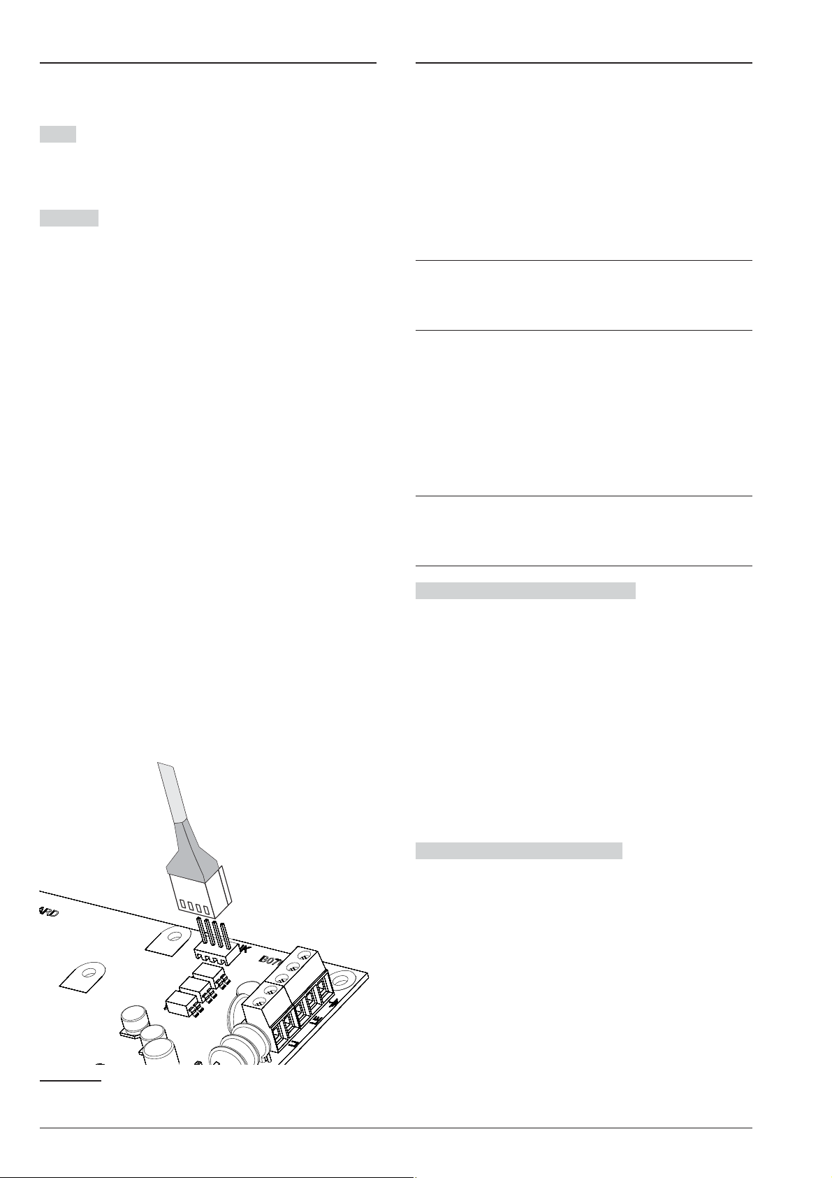
SMS Messages
Downloading/Uploading
This group of options is to setup SMS Messages, as de
scribed below.
Label Assign a label to the message: this information
is not saved in the control panel, which is why the icon
for downloading the option does NOT change its ap
pearance when modified.
Message Enter the required message.
-
-
Once the options have been set up, they must be down
loaded to the Control Panel concerned, as follows.
To perform the Downloading/Uploading you must:
disarmed all the partitions;
Ø
exit from the Installer Menu;
Ø
enter the Installer PIN when required (default 0104
Ø
or 00104 for Grade 3 Control Panels);
connect the Control Panel to the PC on which BOSS
Ø
is installed.
It is also possible to download/upload options us
+
ing a USB key as described in “KEYPAD
OPERATIONS > 2.6) Option Download/Upload via
USB Key”.
Connecting the Control Panel to the PC
n
You can connect the Control Panel to a PC:
locally, via the RS232 Serial Port;
Ø
locally, via the USB Serial Port;
Ø
locally, via LAN net (request the IP Module);
Ø
remotely, via the Internet, via GPRS (request the
Ø
GSM Module);
remotely, viathe Internet, via IP(request the IP Module).
Ø
-
-
In order to comply with EN50131 Grade 3 stan-
3
dards, ONLY use the ABS-IP IP Module to download/upload options remotely: the ABS-GSM
GSM/GPRS Module CANNOT be used.
Connecting via RS232 Serial Port
1. Connect the Control Panel RS232 serial port (10,
PC-LINK) to a free RS232 serial port on the PC us-
ing the PC-LINK cable (accessory item), as shown
on Figure 27.
2. Select the PC serial port used for connection with
the Control Panel, as follows:
– select Modem Manager Configuration from the
Tools menu;
– select the PCLINK - COM1 connection;
– select the PC serial port where the Control Panel
is connected to, from the Port menu;
– click OK.
Connecting via USB Serial Port
1. Connect the Control Panel USB serial port (22)toa
free USB serial port on the PC using the USB-5M
cable (optional) or an equivalent USB cable.
2. Select the PC serial port used for connection with
the Control Panel, as follows:
– select Modem Manager Configuration from the
Tools menu;
– select the PCLINK - COM1 connection;
– select the PC serial port where the Control Panel
is connected to, from the Port menu;
– click OK.
Figure 27 PC-Link connection.
ABSOLUTA PROGRAMMING FROM THE PC 83
Page 84

Connection via Internet (GPRS) To set up connec
tion via Internet (GPRS), to do this:
1. Select the Customer Account properties (right click
on the Customer Account’s name, then Proper
ties).
2. Select the type of control panel (for example,
Absoluta 104 v3.5) from Panels/Modules.
3. Type the Installer PIN in the option BOSS Access
Code (default 0104 or 00104 for Grade 3 Control
Panels).
4. Select Absoluta Plugin from the Module menu
then press Add.
-
-
14. Send the SMS to the Control Panel GSM Module
number before the Connection Timeout time has
passed (see step no. 6).
After receiving the SMS message, if correct, the Control
Panel opens a remote connection via GPRS with the
BOSS application: at this point, options can be down
loaded/uploaded, as outlined in the section “How
Downloading/Uploading the Options”, and the control
panel can be managed through the Status page.
On the router connected to the BOSS PC the for
+
warding port from the BOSS External Port (factory
setting 51004) to port 51004 (internal BOSS port,
CANNOT be changed) must be configured: request
router instructions from the network administrator.
-
-
5. Select Absoluta Plugin from Panels/Modules >
<Control panel Type>
Connection Type menu and press Add.
6. Select GPRS
the telephone number for the GSM Module in the
Panel Phone Number field, select required Con
nection Timeout
7. Select the system properties again (right click on
the system name, then Properties).
8. Select Absoluta Plugin from Panels/Modules >
<Control Panel Type> then enter the Control Panel
Serial Number
9. Open the Customer Account and select Global
Download , Global Upload , or Communicate
Tags .
10. Select GPRS from the Connection Type menu,
then press OK.
11. Type the public IP address of the routerto which the
PC is connected in the option Public IP Address
and select the port to access BOSS (BOSS Exter
nal Port): ask the network administrator or see the
router’s instructions.
12. If this is the first time installed, press APN Settings
and set the APN Name, User Name, and Pass
word for GPRS services (ask the operator of the
GPRS service).
21
20
then select GPRS from the
from Absoluta Plugin then enter
22
and press Save.
23
and press Save.
Connection via LAN (IP) To set up connection via
LAN (IP), proceed as described below (see “APPENDIX
> Connection via IP” for further information.
1. Select the Customer Account properties (right click
on the Customer Account’s name, then Properties).
-
2. Select the type of control panel (for example,
Absoluta 104 v3.5) from Panels/Modules.
3. Type the Installer PIN in the option BOSS Access
Code (default 0104 or 00104 for Grade 3 Control
Panels).
4. Select Absoluta Plugin from the Module menu
then press Add.
5. Select Absoluta Plugin from Panels/Modules >
<Control panel Type> then select IP from the Con-
nection Type menu and press Add.
6. Select IP from Absoluta Plugin then enter the IP ad
dress and the IP Module port
ting 192.168.0.101) and Port options (factory setting
3062) respectively and press Save: at this point it is
-
-
possible to download/upload options as outlined in
the section “How Downloading/Uploading the Op
tions”, and manage the Control Panel via the Status
page.
24
in the IP (factory set
-
-
-
Make sure to type the correct APN for WAP/GPRS
+
access - otherwise some functions may be limited.
13. Prepare an SMS message as outlined in the SMS
Message Generator window then press OK.
20<Control Panel Type> may be Absoluta 16 v3.5, Absoluta 42 v3.5 or Absoluta 104 v3.5.
21When Save is pressed GPRS is replaced by the number entered in Panel Phone Number.
22Connection Timeout is the time the Control Panel waits for a configuration SMS.
23See “KEYPAD OPERATIONS > 3.2) View the Firmware Version” to obtain the Control Panel Serial Number.
24See IP Address and Local BOSS Incoming Port in IP Options Group.
84 Expandable Hybrid Control Panel
Page 85

Connection via Internet (remote IP) To set up con
nection via Internet (remote IP), proceed as described
below (see “APPENDIX > Connection via IP” for further
information.
1. Select the Customer Account properties (right click
on the Customer Account’s name, then Properties).
2. Select the type of control panel (for example,
Absoluta 104 v3.5) from Panels/Modules.
3. Type the Installer PIN in the option BOSS Access
Code (default 0104 or 00104 for Grade 3 Control
Panels).
4. Select Absoluta Plugin from the Module menu
then press Add.
5. Select Absoluta Plugin from Panels/Modules >
<Control panel Type> then select IP (Remote) from
the Connection Type menu and press Add.
-
Notes for Internet connection (GPRS and IP) To
Download/Upload Options via Internet (GPRS and IP):
the PC on which BOSS is installed must be con
Ø
nected to the Internet;
the PC must have a public IP address and a public
Ø
port for incoming connections to the BOSS applica
tion;
the firewall and the router must allow the PC to con
Ø
nect the public port to port 51004 of the BOSS appli
cation;
the ABS-GSM Module must be installed on the con
Ø
trol panel (for connection via GPRS) and/or the
ABS-IP Module (for connection via IP) and their op
tions must be set as described in the paragraph
“ABS-GSM” and/or “ABS-IP”;
a SIM card must be inserted in the GSM Module and
Ø
the credit on the SIM must be sufficient for GPRS
services.
-
-
-
-
-
-
6. Press Save to leave the factory settings
mote IP connection and go to step no. 8, otherwise
read the following step.
7. Select IP (Remote) from Absoluta Plugin then se
lect the time that BOSS waits for the connection request from the IP Module (Connection Timeout),
enter the public IP address for the PC on which
BOSS is installed
the port to access BOSS (BOSS External Port)
then press Save.
8. Select Absoluta Plugin from Panels/Modules >
<Control panel Type> then enter the serial number
of the control Panel and press Save: at this point it
is possible to download/upload options as outlined
in the section “How Downloading/Uploading the
Options”, and manage the Control Panel via the
Status page.
On the router connected to the BOSS PC the for
+
warding port from the BOSS External Port (factory
setting 51004) to port 51004 (internal BOSS port,
CANNOT be changed) must be configured: request
router instructions from the network administrator.
26
(BOSS Public IP) and select
25
for the re
-
-
-
25 The factory settings for remote connection via IP require the Absoluta Server to pass the public IP address for the
PC on which BOSS is installed (option Auto detect ENABLED) and the BOSS External Port 51004 to the IP
Module
26Read the operating system instructions to obtain the public IP address for the PC on which BOSS is installed
ABSOLUTA PROGRAMMING FROM THE PC 85
Page 86

How Downloading/Uploading the Options
n
Once you have set up the connection, you can Down
loading/Uploading the options as follow.
Downloading is the operation that transfers data
+
from PC to Control Panel.
Uploading is the operation that transfers data from
Control Panel to PC.
1. Either select the options to Downloading/Uploading
by enabling the relative Downloading/Uploading
Tabs or jump to the next step to Down
loading/Uploading ALL the options (Global Down
loading/Uploading):
the tag ( ) means that the relative option neither will
Ø
be uploaded nor downloaded;
the blue tag ( ) means that the relative option will
Ø
be uploaded;
the red tag ( ) means that the relative option will be
Ø
downloaded.
-
-
-
You can enable all the group options to be up
loaded/downloaded by clicking on the / icon.
You can clear all the group option tags by clicking on the
icon on the Group toolbar.
You can clear option tags of all Groups by clicking on
the icon on the Main toolbar.
2. Either click on the icon to start the Down-
loading/Uploading of the selected options or click
on the / icon to Downloading/Uploading ALL
the options.
The Global Downloading does not download Voice
+
messages, the Voice Message Labels, the Key
codes and PINs
The Global Uploading does not upload Voice mes
sages, the Voice Message Labels, the Key codes,
the PINs
The application shows the Communicate Tags,
Global Dowload or Global Upload window.
3. Select the Connection Type.
26
27
.
and Event Log28.
-
-
4. Ensure the Access Code is the same as the Con
trol Panel Installer PIN (factory setting: 0104) and
the Identifier is correct (see System Options >
General > Panel Identifier Code).
5. Click OK.
27The PIN can be downloaded/uploaded if the user has enabled the “PIN transfer” option (see “Codes and Keys: User
28The Event Log can be uploaded, if the Events Log option is enabled in the Global Upload window, and from the
Event Log page
-
86 Expandable Hybrid Control Panel
Page 87

KEYPAD OPERATIONS
You can perform the following operation from any LCD
keypad connected to the Control Panel, depending on
your access level.
Operation
Installer Level
View Alarms Yes Yes
Reset Alarms Yes
View Tampers Yes Yes
Reset Tampers Yes
View Faults Yes Yes
Reset Faults Yes
View Bypasses Yes Yes
View Partition Status Yes
View System Status Yes Yes
1.1) Zone Test Yes
1.2) Output Test Yes
1.3) Changing the PIN Yes Yes
1.4) Firmware Upgrade by an USB key Yes
1.6) Modify the LCD Keypad language Yes
1.7) Enabling Level 4 access Yes
1.8) Clear Faults and Tampers Yes
1.9) Option Programming by Keypad Yes
2.1) Voice Message Recording Yes
2.2) BPI Device enrolling Yes
2.3) Wireless Device enrolling Yes
2.4) Key (card/tag) enrolling Yes
2.5) Message Download/Upload via USB Key Yes
2.6) Option Download/Upload via USB Key Yes
2.7) Factory Default Yes
2.8) Telephone Communicator Yes
2.9) Key Disabling/Enabling Yes
3.1) View Logger Yes
3.2) View the Firmware Version Yes Yes
3.3) View Zone Status and Zone Bypassing Yes
3.4) Display GSM Module Status Yes
3.5) Display IP Module Status Yes
In this chapter we refer to the LCD Keypad: the op
+
erations on the Touchscreen Keypad are the
same, unless otherwise indicated
You have the following two access levels.
The Installer Level can perform all the operation
Ø
listed on the previous table, except for the “Firmware
Level 4
Upgrade by an USB key”: the installer Level is dedi
cated to the installer of the system.
The Level 4 can only view the information about the
Ø
system (alarms, tampers, faults, bypass, status and
firmware version) and can perform the “Firmware
Upgrade by an USB key”: the Level 4 is dedicated
only to qualified people by the manufacturer.
The Installer Level access must be enabled by the
+
user, as indicated in the User Manual (OPERATING
YOUR SYSTEM FROM A KEYPAD>Program>Enable Installer (Teleservice) (2.2)): enabled at default.
The Level 4 access must be enabled by the in-
+
staller as indicated in “1.7) Enabling Level 4 access”: disabled at default.
-
-
Using the keypad
The following general rules for the keypad operations
are valid unless otherwise stated.
Ø
Press ENTER to confirm and go to the next step.
Ø
Press ESC to abandon and go to the previous step.
Ø
Press a and b to scroll the options.
Ø
Press c and d to scroll the values.
Ø
Press ON to enable an option.
Ø
Press OFF to disable an option.
The number before the bracket is for the direct ac
+
cess to the relative option, as indicated forward.
-
ABSOLUTA KEYPAD OPERATIONS 87
Page 88
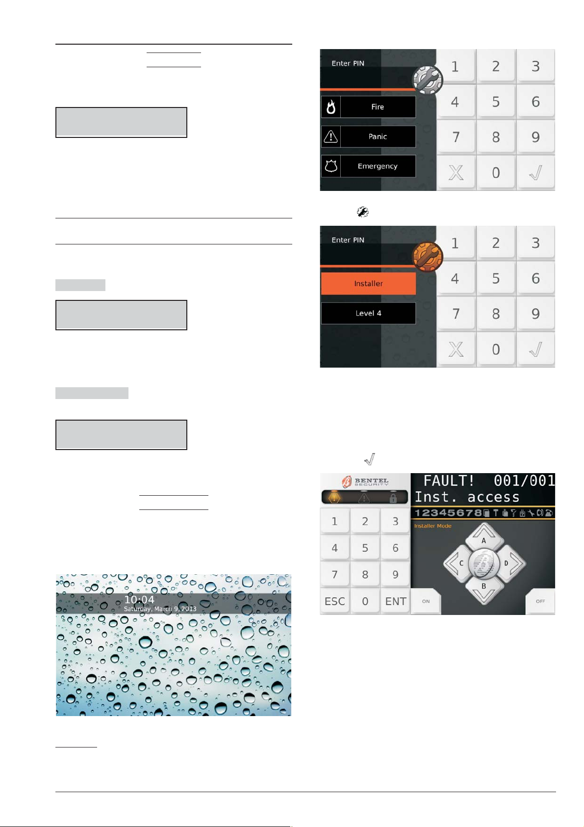
Access to the operations
LCD keypad
2. Tap the screen again:
The display shows the data and time, and the message
Bentel Absoluta
29
on standby status.
Jan/21/11 16:21
Bentel Absoluta
1. Press a then enter the Installer PIN (default 0104 or
00104 for Grade 3 Control Panels) to access the In
staller Level or press b and enter the Level 4 PIN
(default 0400 or 00400 for Grade 3 Control Panels)
to access the Level 4.
The Installer Level and the Level 4 access must be
+
enabled as indicated in the previous page.
2. Press ENTER and read the next paragraphs.
Wrong PIN The display shows the following message:
Jan/21/11 16:21
Wrong PIN
Ø if you do not enter the valid PIN before the 60 sec-
onds timeout expires;
Ø if you enter a wrong PIN.
-
3. Tap :
NOT ALLOWED The display shows the following mes-
sage:
Jan/21/11 16:21
NOT ALLOWED
If access to the Installer Menu of Level 4 has not been
enabled.
TOUCH keypad
In standby, the screen on the Touch Keypad is turned off
or shows theimages selected for the digitalphoto frame.
1. Tap the screen:
4. Select Installer to access the Installer Menu or
Level 4 to access the Level 4 Menu.
5. Enter the Installer PIN (default 0104 or 00104 for
Grade 3 Control Panels) or PIN Level 4 (default
0400 or 00400 for Grade 3 Control Panels), then
press to confirm:
The screen displays a “Virtual keypad” like the one
above.
6. Read the next paragraphs.
29This is the default message. It can be changed by the option System Options > General > LCD Keypad standby
page.
88 Expandable Hybrid Control Panel
Page 89
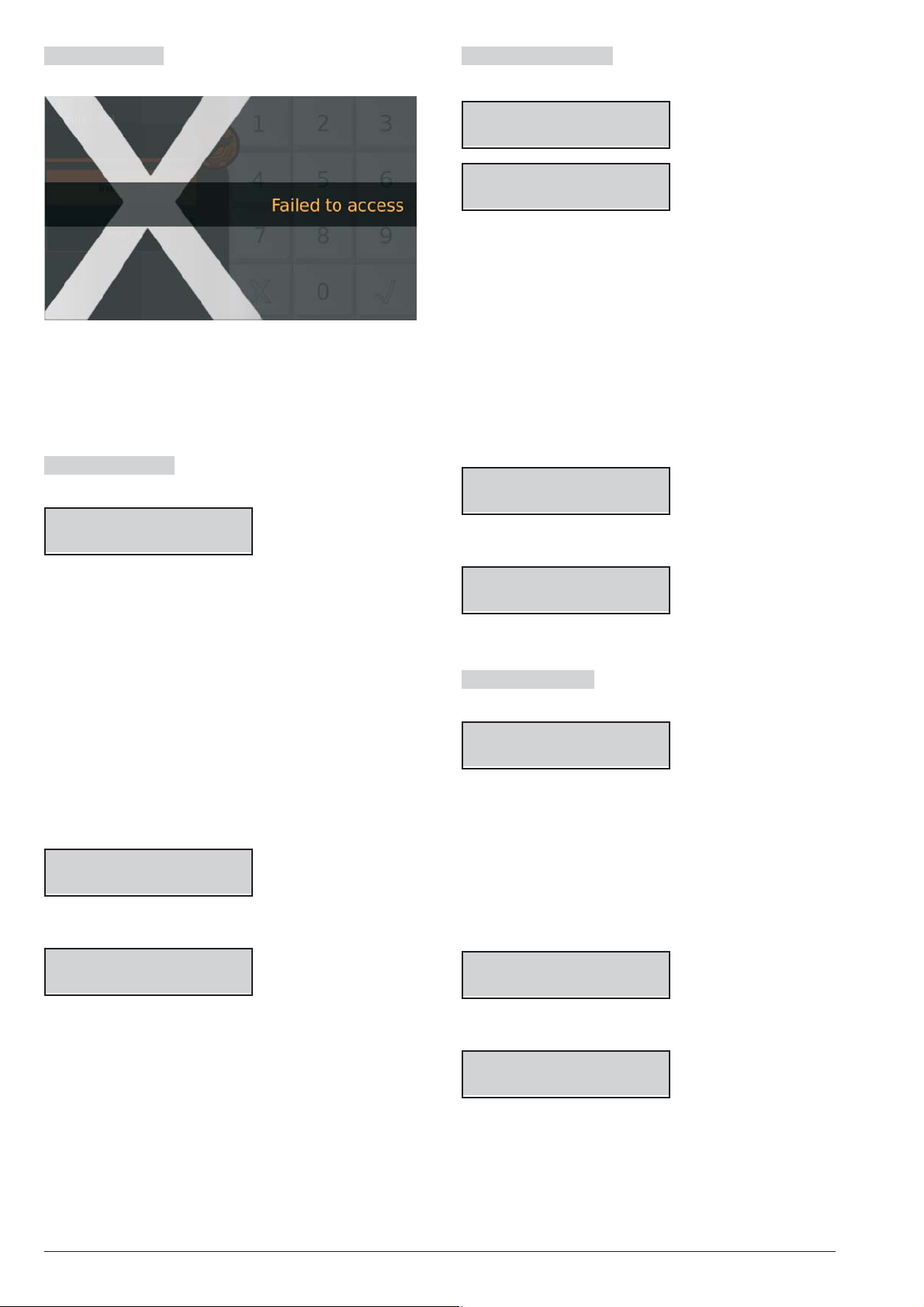
Failed to access The screen displays the following
message:
if you do not enter the valid PIN before the maximum
Ø
time of 60 seconds;
If you enter an incorrect PIN;
Ø
Access to the Installer menu or Level 4 has not been
Ø
enabled.
View/Rest Alarms The keypad shows the Alarms if
present:
*ALARM! 001/003
Zone 001
View/Reset Tampers The keypad shows the Tam
pers if present:
*TAMPER! 001/003
Zone 001
*TAMPER! 001/003
Detector 01
the display top line shows a flashing star (*) on the
Ø
left if the tamper is not longer present (Memory), and
the current tamper displayed respect to the total of
tampers, on the right;
the display bottom line alternatively shows the label
Ø
of the object in tamper status and the tamper cause.
10. Press ENTER to skip to “View/Reset Faults”.
Press A to view the next tamper: if there are no
more tampers to view, the display shows the next
available events (faults or bypass) or the Partition
and System status.
Press OFF to reset the tampers.
Clear Tamper
Are you sure?
11. Press ENTER to confirm.
-
Ø the a light ON indicates alarms in course;
Ø the a light flashing indicates alarms in memory;
Ø the display top line shows a flashing star (*) on the
left if thealarm is not longer present (Alarm Memory),
and the current alarm displayed respect tothe total of
alarms, on the right;
Ø the display bottom line shows the label of the zone in
alarm status.
7. Press ENTER to skip “View/Reset Tampers”.
Press A to view the next alarm: if there are no more
alarms to view, the display shows the next available
events (tampers, faults or bypass) or the Partition
and System status.
Press OFF to reset the alarms.
ALARM Reset
Are you sure?
8. Press ENTER to confirm.
ALARM Reset
Done !!
9. Press ESC to view the next event.
Clear Tamper
Done !!
12. Press ESC to view the next event.
View Reset Faults The keypad shows the Faults if
present:
FAULT! 001/003
Panel NO batt.
Ø
the display top line shows the current fault displayed
respect to the total of faults, on the right;
Ø
the display bottom line shows the fault label.
13. Press ENTER to skip to “View Bypass”.
Press A to view the next fault: if there are no more
faults to view, the display shows the next available
events (bypass) or the Partition and System status.
Press OFF to reset the faults.
Clear Fault
Are you sure?
14. Press ENTER to confirm.
Clear Fault
Done !!
15. Press ESC to view the next event.
ABSOLUTA KEYPAD OPERATIONS 89
Page 90
View Bypass The keypad shows the Bypass if pres
ent:
BYPASS! 001/003
Zone 001
the display top line shows the current bypass dis
Ø
played respect to the total of bypass, on the right;
the display bottom line shows the label of the by
Ø
passed zone.
16. Press ENTER to skip to “View Partition and System
status”.
Press A to view the next bypass: if there are no
more bypasses to view, the display shows theParti
tion and System status.
View Partition and System status The display top
line shows the date and time.
The display bottom line shows the state of the first 8
Partitions, on the left, as follow.
Feb/04/11 14:32
DDDDDDDD
D: Disarmed.
Ø
A: Away Armed.
Ø
Ø S: Stay Armed.
Ø I: Instant Armed (Stay/Away with Zero Delay).
Ø –: Not assigned to the Keypad.
The following information on the right.
-
-
-
-
18. Select the required option then go to the relative
paragraph: you can either select the required op
tion group by pressing the relative key then scroll to
the required option by pressing the key a and b,or
you can directly go to the required option by enter
its address as indicated following.
1: actions
r
1.1: Zone Test
Ø
1.2: Output Test
Ø
1.3: Changing the PIN
Ø
1.4: Firmware Upgrade by an USB key
Ø
1.5: Logger Downloading on a USB key
Ø
1.6: Modify the LCD Keypad language
Ø
1.7: Enabling Level 4 access
Ø
1.8: Clear Faults and Tampers
Ø
1.9: Option Programming by Keypad
Ø
2: programming
r
2.1: Voice Message Recording
Ø
2.2: BPI Device enrolling
Ø
2.3: Wireless Device enrolling
Ø
2.4: Key (card/tag) enrolling
Ø
2.5: Message Download/Upload via USB Key
Ø
2.6: Option Download/Upload via USB Key
Ø
2.7: Factory Default
Ø
2.8: Telephone Communicator
Ø
2.9: Key Disabling/Enabling
Ø
r 3: view
Ø 3.1: View Logger
Ø 3.2: View the Firmware Version
Ø 3.3: View Zone Status and Zone Bypassing
Ø 3.4: View GSM Module Status
Ø 3.5: View IP Module Status.
-
Icon
Signalled by
S x
T x
b x
f x
s x
t *
r *
i
17. Press ENTER to view the Option Menu.
Control Panel Tamper (opened or wall re
moved)
System Tamper (AS terminal)
Peripheral Tamper (Keypad, Key Reader, Ex
pander IN/OUT, Power Station, Wireless Re
ceiver)
False Key
Peripheral Lost (Keypad, Key Reader, Ex
pander IN/OUT, Power Station, Wireless Re
ceiver)
Installer Access enabled (locally and re
motely)
Answerphone facility enabled
Telephone Line busy
Description
INSTALLER
1act. 2prg 3view
Quit from the Operations
Press ESC until the display shows the following mes
-
sage (if you are on the Installer Level):
-
INSTALLER
Exit ?
-
-
or the following message (if you are on the Level 4):
LEVEL 4
Exit ?
-
-
-
Press ENTER to confirm.
The keypad quit from the operations even when
+
you do not press any key before the timeout ex
pires: you have 30 seconds timeout when the key
pad is displaying information about the system
(Alarms, Tampers, Faults, Bypass, Partitions and
Status) and 180 seconds when in the option
menu.
-
-
90 Expandable Hybrid Control Panel
Page 91
1.1) Zone Test
This option will allow you to test all the partition zones
without generating alarms. The Test event will be re
corded in the event logger as: <Alarm - Zone under
test>.
8. Press ENTER to confirm the Partition/Zone se
lected and go back to step 5 and add another parti
tion or zone to be tested:
-
-
-
Partition 01
In Test ON=Start
The Zone Test is possible only when the system is
+
disarmed.
1. Access the Installer menu, as indicated in the para
graph “Access to the operations”.
INSTALLER
1act. 2prg 3view
2. Select the Action option by pressing 1.
INSTALLER 1.1
ZONE test
3. Select the ZONE test option, then press ENTER.
ZONE test
1=Beep_ 2=siren_
4. Select the Test Mode by pressing 1 and/or 2.
Ø 1: the alarm on zone will beep the keypads.
Ø 2: the alarm on zone will sound the sirens.
Then press ENTER.
ZONE test
Part=-- Zone ---
5. Press c or d to select the zones to be tested:
Ø Part=, select ALLzones of the Partition (see step 6);
Ø
Zone=, select a single Zone (see Step 7).
6. Select the Partition to test by pressing a or b to
scroll the Partitions or by entering the relative ID
number: the LCD top line shows the label of the se
lected Partition.
Partition 01
Part=01 Zone ---
9. Press ON to start the Test:
Test on going
-
10. Perform the test on the selected zones:
the keypad beeps, if enabled (refer to step 4);
Ø
the siren sounds, if enabled (refer to step 4);
Ø
the display upper line shows the tested zones re
Ø
spect to the zones to be tested;
the display bottom line shows the labelof the tested zone.
Ø
-
TEST! 001/008
Zone 001
11. Press b to view the lowest tested zone.
TEST! 008/008
Zone 001
12. Press a to scroll the tested zones.
TEST! 008/008
Zone 002
13. Press d to view the result of the test of the zone dis-
played on the line below the display:
an x indicates the tested status, as follow.
Ø A: Alarm
Ø
o: Open
Ø
s: Short circuit
Ø
T: Tamper
Ø
-
F: Fault
Ø
M: Masking
Ø
B: Battery Low
AosTFMB
x______
7. Select the Zoneto test by pressing a or b to scroll the
zones or by entering the relative ID number: the Dis
play top line shows the label of the selected Zone.
Zone 001
Part -- Zone=001
-
Press c to go back to step 12 or press ESC to quit the
Zone Test.
The Installer Menu Timeout is suspended during
+
the Zone Test, giving you the time to perform the
test. The keypad exits from the Installer Menu
when you press ESC after the Installer Menu Time
out has expired.
The tamper continues to work properly, during the
+
test: information on the keypads, event logger, out
puts and telephone actions.
ABSOLUTA KEYPAD OPERATIONS 91
-
-
Page 92
1.2) Output Test
1.3) Changing the PIN
This option will allow you to test the system Outputs.
1. Access the Installer menu, as indicated in the para
graph “Access to the operations”.
INSTALLER
1act. 2prg 3view
2. Select the Action option by pressing 1.
INSTALLER 1.1
ZONE test
3. Select the OUTPUT test option.
INSTALLER 1.2
OUTPUT test
4. Press ENTER.
On/Off Output -
5. Enter the ID Number relevant to the Software Out
put to be tested: the display bottom line shows the
label of the selected output.
If the corresponding Output is active the second
+
line blinks
This option will allow to you to change the Installer PIN
or the Level 4 PIN, depending on the menu you are run
-
ning (Installer Menu or Level 4 Menu): the default In
staller PIN is 0104 (00104 for Grade 3 Control Panels);
the default Level 4 PIN is 0400 (00400 for Grade 3 Con
trol Panels).
You must press A, before enter the Installer PIN, to
+
access the Installer Menu, and B, before enter the
Level 4 PIN, to access the Level 4 Menu.
You can change the PIN as follow.
1. Access the Installer menu or the Level 4 menu, as
indicated in the paragraph “Access to the opera
tions”.
-
-
-
-
INSTALLER
1act. 2prg 3view
2. Select the Action option by pressing 1.
INSTALLER 1.1
ZONE test
-
3. Select Change My PIN.
INSTALLER 1.3
Change my PIN
On/Off Output 01
Output 01
6. Press ON to activate the selected Output.
Output 01
Activated
7. Press OFF to deactivate the selected Output.
Output 01
Deactivated
8. Press ON to re-activate the selected Output or
press ESC to select a different Output and go back
to step 5.
4. Press ENTER.
INSTALLER
New PIN
5. Enter the new Installer PIN, then press ENTER.
INSTALLER
Again
6. Enter again the new Installer PIN, then press
ENTER:
Ø
if the entries match, the new Installer PIN will be
memorized and the Keypad go back to step 3,
Ø
otherwise the Keypad will sound the error signal and
go back to step 4.
92 Expandable Hybrid Control Panel
Page 93
1.4) Firmware Upgrade by an USB key
To manage this operation it is necessary to enable
+
the PIN of Level 4 (refer to “1.7) Enabling Level 4
access”).
This operation updates the firmware for the Control
Panel and the GSM and IP Modules, if installed and
present in the configuration (see the Present option in
the GSM and IP options groups).
1. Download the required firmware from site
www.bentelsecurity.com
a USB key; ensure the USB key has the folder
K_FW (K_FWG3 for Grade 3 control panels).
and unzip the ZIP file onto
8. The Control Panel will restarts if the firmware up
grading succeeds otherwise the display shows:
USB operation
Failed
if the USB key is NOT inserted in the Control Panel
Ø
USB port;
if the USB key is NOT compatible with the Control
Ø
Panel (the Control Panel supports FAT32 formatting
not NTFS);
if the firmware has NOT been downloaded into the
Ø
K_FW folder (K_FWG3 for Grade 3 control panels)
on the USB key;
if the downloaded firmware is wrong or corrupt.
Ø
-
2. Insert the USB key in the USB port 1 on the Control
Panel (refer to the Figure 1 on page 15).
3. Access the Level 4 menu, as indicated in the para
graph “Access to the operations”.
LEVEL 4
1act. 3view
4. Select the Action option by pressing 1.
LEVEL 4 1.3
Change my PIN
5. Select ABS Upgrade.
LEVEL 4 1.4
ABS Upgrade
6. Press ENTER.
ABS Upgrade
USB -> FW
7. Select USB -> FW and press ENTER.
Or shows:
USB operation
-
ABS not upgraded
if the Control Panel update was unsuccessful;
Ø
USB operation
GSM not upgraded
if the GSM module update was unsuccessful;
Ø
USB operation
IP not upgraded
Ø if the IP module update was unsuccessful.
9. In these cases press ESC to go back to the Installer
Menu and repeat the operation after you have
checked that:
Ø the GSM is correctly installed, present in the Control
Panel configuration and NOT malfunctioning (see
“3.4) View GSM Module Status”);
Ø
the IP is correctly installed, present in the Control
Panel configuration and NOT malfunctioning (see
“3.5) View IP Module Status”);
Working
Please Wait
You can view the current Firmware of Control
+
Panel, of the GSM Module and IP Module as de
scribed in “3.2) View the Firmware Version” in this
section.
When you update the firmware , wait for the second
+
restart before attempt any operation.
ABSOLUTA KEYPAD OPERATIONS 93
-
Page 94
1.6) Modify the Keypad language
1.7) Enabling Level 4 access
You can modify the Keypad language as follow.
1. Access the Installer menu, as indicated in the para
graph “Access to the operations”.
INSTALLER
1act. 2prg 3view
2. Select the Action option by pressing 1.
INSTALLER 1.1
ZONE test
3. Select Modify Lang.
INSTALLER 1.6
Modify Lang.
4. Press ENTER: the Keypad display shows the avail
able languages.
Mod. Lingua 1/9
1=Italiano
Modify Lang. 2/9
2=English
Level 4 is reserved to qualified personal to upgrade the
Control Panel Firmware: Level 4 access is Disabled by
-
default.
You can enable/disable the Level 4 access as follow.
1. Access the Installer menu, as indicated in the para
graph “Access to the operations”.
-
INSTALLER
1act. 2prg 3view
2. Select the Action option by pressing 1.
INSTALLER 1.1
ZONE test
3. Select Enable lev. 4.
-
INSTALLER 1.7
ON/OFF level 4
4. Press OFF to disable Level 4 access (PIN) then
press ESC to go back to the Installer Menu.
ON/OFF level 4
Disabled
5. Select the required language by pressing the relative key: the language of the Keypad in use will
change immediately.
5. Press ON to enable Level 4 access (PIN) then
press ESC to go back to the Installer Menu.
ON/OFF level 4
Enabled
94 Expandable Hybrid Control Panel
Page 95
1.8) Clear Faults and Tampers
1.9) Option Programming by Keypad
You can clear fault and tamper signalling as follow.
1. Access the Installer menu, as indicated in the para
graph “Access to the operations”.
INSTALLER
1act. 2prg 3view
2. Select the Action option by pressing 1.
INSTALLER 1.1
ZONE test
3. Select Clear Fault/Tamp.
INSTALLER 1.8
Clear Fault/Tamp
4. Press ENTER.
Clear Fault/Tamp
1=Fau._ 2=Tam._
5. Select the action required by pressing the relative
key.
Ø 1: the Fault signalling will be cleared.
Ø 2: the Tamper signalling will be cleared.
You can programming the main Control Panel options
by an LCD Keypad as follow.
-
1. Access the Installer menu, as indicated in the para
graph “Access to the operations”.
-
INSTALLER
1act. 2prg 3view
2. Select the Action option by pressing 1.
INSTALLER 1.1
ZONE test
3. Select Panel Prog.
INSTALLER 1.9
Panel Prog.
4. Press ENTER.
Panel Prog.
Zones Zn---
5. Select the Option Group you want set up by pressing a and b then press ENTER and refer to the relative paragraph.
Clear Fault/Tamp
1=Fau.* 2=Tam.*
6. Press ENTER to perform the selected actions.
Clear Fault&Tamp
Are you sure?
7. Press ENTER again to confirm your choice or press
ESC to go back to step 5.
Clear Fault&Tamp
Done !!
8. Press ESC to go back to step 3.
The Installer Menu Timeout is suspended during
+
the Option Programming. The keypad exits from
the Installer Menu when you press ESC after the
Installer Menu Timeout has expired.
n Zones
Panel Prog.
Zones Zn---
The Zone option let you to set up the Zone Partitions as
follow.
1. Enter the Identification Number of the Zone you
want set up.
Zone 001
Zones Zn001
2. Press ENTER.
Zones Zn001
Part mask
3. Press ENTER again: the characters on the display
bottom line show the Partitions of the selected
zone: the 1stis for Partition 1, the 2nd is for Partition
2 and so on, as follow.
Ø
*: the Zone is assigned to the Partition.
Ø
-: the Zone is NOT assigned to the Partition.
ABSOLUTA KEYPAD OPERATIONS 95
Page 96
Part mask Zn001
*---------------
4. Set up the Zone Partitions as follow.
Press a to assign ALL the Partitions to the Zone.
Ø
Press b to assign none Partition to the zone.
Ø
Press c and d to scroll the Partitions: a blinking char
Ø
acter indicates the currently selected Partition.
Press ON to assign the selected Partition to the
Ø
Zone.
Press OFF to NOT assign the selected Partition to
Ø
the Zone.
Press ENTER to confirm the Zone Partitions or ESC
Ø
to discharge the changes, and go back to step 1.
Part mask Zn001
*--------------*
In the top example, Zone 1 is assigned to the Partitions
1 and 16.
Partition
n
Panel Prog.
Partition Pt---
User PINs
n
Panel Prog.
Users UC---
The User PINs option let you to set up the PIN Parti
-
tions as follow.
1. Enter the Identification Number of the User PIN you
want set up.
-
User 001
Users UC001
2. Press ENTER.
Users UC001
Part mask
3. Press ENTER again: the characters on the display
bottom line show the Partitions of the selected User
PIN : the 1st is for Partition 1, the 2nd is for Partition
2 and so on, as follow.
*: the User PIN is assigned to the Partition.
Ø
-: the User PIN is NOT assigned to the Partition.
Ø
The Partition option let you to set up the Entry and Exit
Times for the Partitions, as follow.Enter the Identification Number of the Zone you want set up.
1. Enter the Identification Number of the Partition you
want set up.
Partition 01
Partition Pt001
2. Press ENTER.
Partition Pt001
Entry time
3. Press a and b to scroll the Entry time and Exit
time, then press ENTER to select the displayed op
tion: the displaybottom line shows the current value
on the left, and the valid range on the right.
Entry time Pt001
30s : 15/3600
4. Enter the required value.
Ø
You must enter a 4-digit value: e.g. you must press 0,
0, 6 and 0 to enter 60 seconds.
Ø
Press ESC to delete the value.
Ø
Press ESC again to to discharge the changes and go
back to step 3.
Ø
Press ENTER to confirm the value and go back to
step 3.
Part mask UC001
****************
4. Set up the User PIN Partitions as described for the
zones.
Ø In the top example, User PIN 1 is assigned to the
Partitions 1 and 16.
n Keys
Panel Prog.
Keys K---
The Keys option let you to set up the Keys Partitions as
described for the zones.
n
-
WLS Keys
Panel Prog.
WLS keys WK---
The WLS Keys option let you to set up the Wireless
Keys Partitions as described for the zones.
96 Expandable Hybrid Control Panel
Page 97
System
n
2.1) Voice Message Recording
Panel Prog.
System
The System option is for setting the Control Panel ID
Number, as follows.
1. Press ENTER:
System
Panel ID
2. Press ENTER again: the display shows the current
ID number in the bottom left:
System
0000 : 0/9999
3. Enter the ID number of the Control Panel (0 to
9999) and then press ENTER to confirm or ESC to
cancel and go back in step 1.
Key Reader
n
Panel Prog.
Key Reader KR---
The Key Reader option is for setting the Reader Partitions, as described for zones.
n Keypad
Panel Prog.
KeyPad KP---
You can recording and playback the Voice Messages
by means the Audio Station AS100, as follow.
1. Access the Installer menu, as indicated in the para
graph “Access to the operations”.
INSTALLER
1act. 2prg 3view
2. Select the Programming option by pressing 2.
INSTALLER 2.1
Voice Messages
3. Select Voice Messages.
INSTALLER 2.1
Voice Messages
4. Press ENTER.
Message Num. ---
5. Enter the ID number of the Voice Message to record/playback, then press ENTER. The display upper line show the selected message on the right its
status on the left:
Ø Free: the Message is empty;
Ø Used: the Message is already used.
M001 Free
1=> 2=Rec 3=Stop
-
The Keypad option is for setting the Keypad Partitions,
as described for the zones.
6. Press 1 to play the message. Press 3 to stop the
playback. A bar on the display upper line shows the
play progress.
Ø
*: the play time.
Ø
=: the Message length.
Ø
-: the free space.
M001 play *==--1=> 2=Rec 3=Stop
7. Press 2 to record a new message. Press 3 to stop
the recording. A bar on the display upper line shows
the recording progress.
Ø
*: the recording time.
Ø
=: the free space.
M001 rec. *=====
1=> 2=Rec 3=Stop
ABSOLUTA KEYPAD OPERATIONS 97
Page 98
2.2) BPI Device enrolling
2.3) Wireless Device enrolling
You can perform the BPI Device enrolling when you
change the BPI bus configuration, as follow.
1. Access the Installer menu, as indicated in the para
graph “Access to the operations”.
INSTALLER
1act. 2prg 3view
2. Select the Programming option by pressing 2.
INSTALLER 2.1
Voice Messages
3. Select BPI Enroll.
INSTALLER 2.2
BPI Enroll
4. Press ENTER. The Control Panel takes a few sec
ond to check the devices on the BPI bus:
the display shows the following message if the BPI
Ø
bus configuration matches with the currently in the
Control Panel memory.
Devices match
ESC or ENT=modif
You can enroll the Wireless Devices and perform the
Placement Test as follow.
-
1. Access the Installer menu, as indicated in the para
graph “Access to the operations”.
-
INSTALLER
1act. 2prg 3view
2. Select the Programming option by pressing 2.
INSTALLER 2.1
Voice Messages
3. Select WIRELESS Config.
INSTALLER 2.3
WIRELESS Config.
-
4. Press ENTER.
WIRELESS Config.
1=Zn 2=K 3=Test
5. Press 1 to enroll Wireless Detectors, 2 to enroll
Wireless Keys, 3 to perform the Placement Test,
the refer to the relative paragraph below.
Ø Otherwise, the display shows the new BPI bus con-
figuration.
Kb=01 Kr=01 Al=0
Ei=01 Eo=01 OK?
5. Press ENTER to modify the configuration (refer to
“Auto-configuration (Wizard setup)” in the
“INSTALLING” section for more details) or ESC to
quit.
If you made any changes, simply press OFF to
+
make a new configuration, without having to repeat
the procedure from the beginning.
Wireless Detector
WIRELESS Config.
Zone 013
6. Select the required Position (Zone/Slot) for the
Wireless Detector, then press ENTER.
The display prompts the first free Software Zone.
+
note:ON=E, OFF=F
ESN ------
7. Enter the 6-digit Electronic Serial Number you can
find on the Wireless Detector (refer to the Detec
tor’s instructions for more details):
Ø
use the cursors keys a, b, c, and d to enter respec
tively the digits A, B, C and D;
Ø
press ON to enter E;
Ø
press OFF to enter F.
note:ON=E, OFF=F
ESN 299AFC
-
-
8. Press ENTER.
98 Expandable Hybrid Control Panel
Page 99
WLS zone type
1=int._ 2=delay_
9. Set up the Wireless Zone Type, then press ENTER
and go back to step 5.
1:Internal.
Ø
2: Delayed.
Ø
Wireless Keys
2.4) Key enrolling
You can enroll the Digital Keys as follow.
1. Access the Installer menu, as indicated in the para
graph “Access to the operations”.
INSTALLER
1act. 2prg 3view
-
WIRELESS Config.
Key 001
10. Select the required Position (Slot) for the Wireless
Key, then press ENTER.
note:ON=E, OFF=F
ESN ------
11. Enter the 6-digit Electronic Serial Number you can
find on the Wireless Key, as per the Wireless De
tectors.
note:ON=E, OFF=F
ESN 6989E2
12. Press ENTER and go back to step 5.Wireless Detector
Placement Test
WLS placem. Test
Zone 013
13. Select the (Detector) Wireless Zone to test, then
press ENTER.
The display prompts the first Wireless Zone of the
+
System.
2. Select the Programming option by pressing 2.
INSTALLER 2.1
Voice Messages
3. Select Key programming.
INSTALLER 2.4
Key programming
-
4. Press ENTER.
Key programming
on Reader ---
5. Select the Key Reader to enroll the Keys, then
press ENTER.
Key programming
Key ---
6. Select the Key slot, then press ENTER: ALL the selected Key Reader’s LEDs fast blinking to indicate
that it is waiting for a Key.
if the display shows the message Key active,
+
the selected slot is already used by a Key. Press
ESC and select a free slot or press ENTER to over
write the position with the new Key.
-
Result .....
Key programming
Wait for key
14. Perform the Placement Test as indicated in the De
tector’s instructions.
Result .....
GOOD!!
Ø
If the result is GOOD, you can mount the detector in
the selected placement: press ESC and go back to
step 13.
Result .....
-
7. Present the Key to the selected Key Reader: the
green indicator light and the Keypad sounds a dou
ble beep to indicate that the Key has been enrolled
and go back to step 6.
if the display shows the message Key used, the
+
yellow indicator on the Reader blinks quickly and
the Keypad sounds a single beep, the key is al
ready enrolled on a different slot. Press ESC and
go back to step 6.
BAD!!
Ø
If the result is BAD, you must move the Detector in a
different position and try again: press ESC and go
back to step 13.
ABSOLUTA KEYPAD OPERATIONS 99
-
-
Page 100
2.5) Message Download/Upload via USB Key
2.6) Option Download/Upload via USB Key
You can use a USB key to transfer the Voice Messages
from the PC to the Control Panel and vice versa, and
from a Control Panel to another, as follow.
1. Insert an USB key in the USB port (22) of the Con
trol Panel (see the Figure 1 on page 15).
2. Access the Installer menu, as indicated in the para
graph “Access to the operations”.
INSTALLER
1act. 2prg 3view
3. Select the Programming option by pressing 2.
INSTALLER 2.1
Voice Messages
4. Select USB <-> AUDIO.
INSTALLER 2.5
USB <-> AUDIO
5. Press ENTER.
USB <-> AUDIO
Load from USB?
6. Select Load from USB to transfer the Voice Messages from the USB Key to Control Panel.
Select Save in USB to transfer the Voice Messages from the Control Panel to the USB Key.
Then Press ENTER.
Working
Wait Please
7. The Keypad display will show the following mes
sage if the operation succeeds: press ESC to go
back to the Installer Menu.
Using a USB key you can Download/Upload the Op
tions between PC and Control Panel, and between dif
ferent Control Panels, as follow.
The Installer PIN of the Panel/BOSS that has gen
-
-
+
erated the option file must match with the Installer
PIN of the Panel/BOSS that loads the file option.
It is possible to Download/Upload options between
+
control panels of the same type and firmware ver
sion ONLY.
All connections from the USB 21 port must be re
+
moved (Figure 1 on page 15).
1. Insert an USB key in the USB port (22) of the Con
trol Panel (see Figure 1 on page 15).
2. Access the Installer menu, as indicated in the para
graph “Access to the operations”.
3. Select the Programming option by pressing 2.
-
-
-
-
-
-
-
INSTALLER 2.1
Voice Messages
4. Select USB <-> AUDIO.
INSTALLER 2.6
USB <-> PROG
5. Press ENTER.
USB <-> PROG
Load from USB?
6. Select Load from USB to upload the Options from
the USB Key to Control Panel.
Select Save in USB to transfer the Options fromthe
-
Control Panel to USB Key. Then Press ENTER.
Working
Wait Please
USB operation
Done !!
8. The Keypad display will show the following mes
sage if the operation fails.
USB operation
Failed
9. Press ESC to go back to the Installer Menu and re
peat the operation after you have checked that:
Ø
the Installer PIN, of the control panel, is the same as
the one used for recording voice messages (see
“Voice Messages Recording”);
Ø
you have inserted the USB key in the USB porton the
Control Panel;
Ø
the used USB key is supported by theControl Panel (the
Control Panel supports FAT32 formatting not NTFS);
Ø
you have enough space free on the USB key;
Ø
you have downloaded Voice Messages on the USB key.
-
-
7. The Keypad display will show the following mes
sage if the operation succeeds: press ESC to go
back to the Installer Menu.
USB operation
Done !!
8. The Keypad display will show the following mes
sage if the operation fails.
USB operation
Failed
9. Press ESC to go back to the Installer Menu and re
peat the operation after you have checked that:
Ø
you have inserted the USB key in the USB porton the
Control Panel;
Ø
the used USB key is supported by theControl Panel (the
Control Panel supports FAT32 formatting not NTFS);
Ø
you have enough space free on the USB key;
Ø
you have downloaded the Options on the USB key.
100 Expandable Hybrid Control Panel
-
-
-
 Loading...