

Page 1
®
INSTALLATION MANUAL
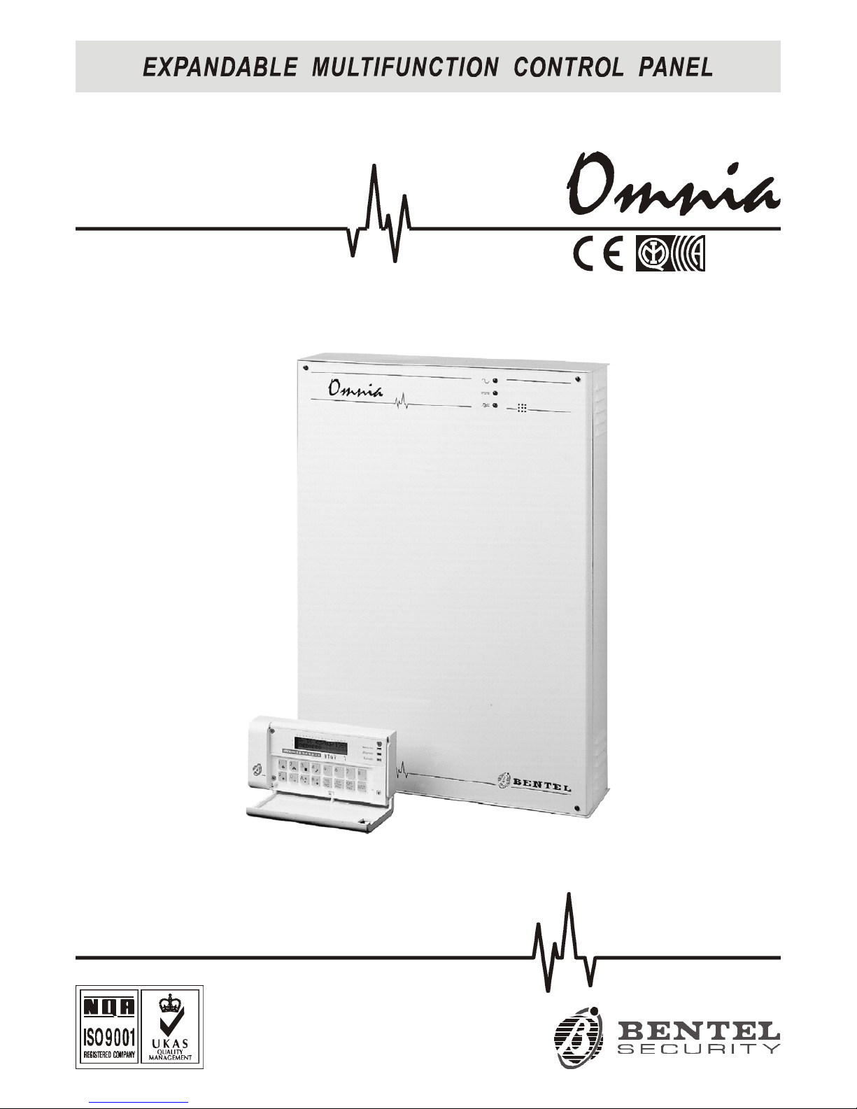
Omnia/S
DAT n. U0805
Page 2

This Security panel can be programmed via the OMNIA 3.0 Software Application or higher.
Hereby, Bentel Security,
declares that the above mentioned Omnia/S is in compliance with the essential requirements and
other relevant provisions of Directive
1999/5/EC1999/5/EC.
The complete R&TTE Declaration of Conformity for each Panel can be found
at
www.bentelsecurity.com/dc.htmlwww.bentelsecurity.com/dc.html.
This control panel complies with
CEI 79-2 2a Ed.1993CEI 79-2 2a Ed.1993.
Installation of these systems must be carried out strictly in accordance with the instructions described in this manual, and in compliance with the local laws and bylaws in force.
The above mentioned Omnia/S has been designed and made to the highest standards of quality and performance.
The manufacturer recommends that the installed system should be completely tested at least once a
month.
BENTEL SECURITY srl shall not be responsible for damage arising from improper installation or maintenance by unauthorized personnel.
BENTEL SECURITY srl reserves the right to change the technical specifications of this product without prior notice.
Page 3

TABLE OF CONTENTS
INTRODUCTION 5
Overview . . . . . . . . . . . . . . . . . . . . . . . . . . . 5
Main features . . . . . . . . . . . . . . . . . . . . . . . . . 5
The Omnia Panel . . . . . . . . . . . . . . . . . . . . . . . 6
Technical Specifications . . . . . . . . . . . . . . . . . . . 7
Accessories . . . . . . . . . . . . . . . . . . . . . . . . . . 7
Update . . . . . . . . . . . . . . . . . . . . . . . . . . . . . 10
Omnia 2.1 . . . . . . . . . . . . . . . . . . . . . . . . . . . 10
Omnia 3.0 . . . . . . . . . . . . . . . . . . . . . . . . . . . 10
Omnia 3.1 . . . . . . . . . . . . . . . . . . . . . . . . . . . 10
DESCRIPTION OF PARTS 11
Main unit . . . . . . . . . . . . . . . . . . . . . . . . . . . . 11
Keypad . . . . . . . . . . . . . . . . . . . . . . . . . . . . 13
Readers . . . . . . . . . . . . . . . . . . . . . . . . . . . . 15
Input and Output expanders . . . . . . . . . . . . . . . . . . 16
INSTALLATION 17
Installing the Panel . . . . . . . . . . . . . . . . . . . . . . 17
Terminal board description . . . . . . . . . . . . . . . . . 21
The Panel . . . . . . . . . . . . . . . . . . . . . . . . . . . 21
BPI Peripherals . . . . . . . . . . . . . . . . . . . . . . . . 22
Schematic diagrams . . . . . . . . . . . . . . . . . . . . . 22
Connecting BPI Peripherals . . . . . . . . . . . . . . . . . 23
BPI Bus wiring limitations . . . . . . . . . . . . . . . . . . . 24
Connecting Alarm sensors . . . . . . . . . . . . . . . . . 24
Connecting Fire sensors . . . . . . . . . . . . . . . . . . . . 26
Connecting Signalling devices . . . . . . . . . . . . . . . 27
Connecting Tamper terminals . . . . . . . . . . . . . . . . 27
Connecting the Telephone-line . . . . . . . . . . . . . . . 27
Connecting the Power supply . . . . . . . . . . . . . . . . 28
PROGRAMMING 29
Customer data . . . . . . . . . . . . . . . . . . . . . . . . 30
Configuration . . . . . . . . . . . . . . . . . . . . . . . . . 31
Keypads . . . . . . . . . . . . . . . . . . . . . . . . . . . . 31
Readers . . . . . . . . . . . . . . . . . . . . . . . . . . . . 32
Wireless . . . . . . . . . . . . . . . . . . . . . . . . . . . . 32
Zones . . . . . . . . . . . . . . . . . . . . . . . . . . . . . 32
Zone Table . . . . . . . . . . . . . . . . . . . . . . . . . . . 32
Zone programming . . . . . . . . . . . . . . . . . . . . . . 33
Type . . . . . . . . . . . . . . . . . . . . . . . . . . . . . . 33
Attributes . . . . . . . . . . . . . . . . . . . . . . . . . . . . 34
Balance Type . . . . . . . . . . . . . . . . . . . . . . . . . 34
Cycles . . . . . . . . . . . . . . . . . . . . . . . . . . . . . 35
Partition . . . . . . . . . . . . . . . . . . . . . . . . . . . . 35
Sensitivity . . . . . . . . . . . . . . . . . . . . . . . . . . . 35
Voice messages . . . . . . . . . . . . . . . . . . . . . . . . 35
Outputs . . . . . . . . . . . . . . . . . . . . . . . . . . . . 36
Outputs page . . . . . . . . . . . . . . . . . . . . . . . . . 36
Description . . . . . . . . . . . . . . . . . . . . . . . . . . . 36
Reserved Outputs (manual) . . . . . . . . . . . . . . . . . . 37
Type . . . . . . . . . . . . . . . . . . . . . . . . . . . . . . 37
Attribute . . . . . . . . . . . . . . . . . . . . . . . . . . . . 37
Times . . . . . . . . . . . . . . . . . . . . . . . . . . . . . 37
Off Time . . . . . . . . . . . . . . . . . . . . . . . . . . . . 37
Partitions . . . . . . . . . . . . . . . . . . . . . . . . . . . 38
Telephone . . . . . . . . . . . . . . . . . . . . . . . . . . 39
Answer . . . . . . . . . . . . . . . . . . . . . . . . . . . . 39
Dialling mode . . . . . . . . . . . . . . . . . . . . . . . . . 40
PSTN line parameters . . . . . . . . . . . . . . . . . . . . 40
Answering machine feature . . . . . . . . . . . . . . . . . . 40
Dialler . . . . . . . . . . . . . . . . . . . . . . . . . . . . . 41
Dialler Telephone Numbers . . . . . . . . . . . . . . . . . 41
Messages . . . . . . . . . . . . . . . . . . . . . . . . . . . 42
Actions . . . . . . . . . . . . . . . . . . . . . . . . . . . . 42
Digital Communicator . . . . . . . . . . . . . . . . . . . . 43
Digital Communicator telephone numbers . . . . . . . . . . 43
Actions . . . . . . . . . . . . . . . . . . . . . . . . . . . . 44
Teleservice . . . . . . . . . . . . . . . . . . . . . . . . . . 46
Event-Actions . . . . . . . . . . . . . . . . . . . . . . . . 47
Events Table . . . . . . . . . . . . . . . . . . . . . . . . . 47
Priority telephone actions . . . . . . . . . . . . . . . . . . . 47
Actions . . . . . . . . . . . . . . . . . . . . . . . . . . . . 48
View event details . . . . . . . . . . . . . . . . . . . . . . . 48
Clear actions . . . . . . . . . . . . . . . . . . . . . . . . . 48
Events description . . . . . . . . . . . . . . . . . . . . . 48
Alarm events . . . . . . . . . . . . . . . . . . . . . . . . . 48
Generic Events . . . . . . . . . . . . . . . . . . . . . . . . 50
Spot events . . . . . . . . . . . . . . . . . . . . . . . . . . 52
DTMF communicator (for Firmware Versions lower than 3.0) ...................53
Test event . . . . . . . . . . . . . . . . . . . . . . . . . . 54
Keypad Codes . . . . . . . . . . . . . . . . . . . . . . . . 54
User Code Description . . . . . . . . . . . . . . . . . . . . 54
Code attributes programmed by the Installer . . . . . . . . . 55
User Parameters . . . . . . . . . . . . . . . . . . . . . . . 55
Programming Access Codes . . . . . . . . . . . . . . . . . 57
Attributes programmed by the user . . . . . . . . . . . . . . 58
Digital Keys . . . . . . . . . . . . . . . . . . . . . . . . . 59
Super keys . . . . . . . . . . . . . . . . . . . . . . . . . . 59
Filter times . . . . . . . . . . . . . . . . . . . . . . . . . . 59
Options . . . . . . . . . . . . . . . . . . . . . . . . . . . . 60
Scheduler . . . . . . . . . . . . . . . . . . . . . . . . . . 61
LCD strings . . . . . . . . . . . . . . . . . . . . . . . . . 61
Clock . . . . . . . . . . . . . . . . . . . . . . . . . . . . . 61
Installer code . . . . . . . . . . . . . . . . . . . . . . . . 61
On-site Downloading from computer . . . . . . . . . . . 62
Remote Downloading from computer . . . . . . . . . . . 63
Programming from Keypad . . . . . . . . . . . . . . . . . 64
Reset default . . . . . . . . . . . . . . . . . . . . . . . . . 64
Defaults . . . . . . . . . . . . . . . . . . . . . . . . . . . . 64
A basic system . . . . . . . . . . . . . . . . . . . . . . . 65
Connections . . . . . . . . . . . . . . . . . . . . . . . . . . 65
Programming . . . . . . . . . . . . . . . . . . . . . . . . . 65
3
Page 4

Using the system . . . . . . . . . . . . . . . . . . . . . . . 65
OmniaVOX 67
Features . . . . . . . . . . . . . . . . . . . . . . . . . . . . 67
Parts identification . . . . . . . . . . . . . . . . . . . . . . 67
Installation . . . . . . . . . . . . . . . . . . . . . . . . . . 67
Expand Listen-in partitions . . . . . . . . . . . . . . . . . 68
Manual selection . . . . . . . . . . . . . . . . . . . . . . . . 68
Auto-select mode . . . . . . . . . . . . . . . . . . . . . . . 68
Manual and Auto-select mode . . . . . . . . . . . . . . . . . 69
OmniaTIMER 71
General features . . . . . . . . . . . . . . . . . . . . . . . 71
Parts identification . . . . . . . . . . . . . . . . . . . . . . 71
Installation . . . . . . . . . . . . . . . . . . . . . . . . . . 71
Programming . . . . . . . . . . . . . . . . . . . . . . . . . 73
Operations . . . . . . . . . . . . . . . . . . . . . . . . . . 75
Timers . . . . . . . . . . . . . . . . . . . . . . . . . . . . 76
Connecting the Computer . . . . . . . . . . . . . . . . . 76
FACILITIES 77
Fast arming . . . . . . . . . . . . . . . . . . . . . . . . . 77
Temporary disarming (patrol) . . . . . . . . . . . . . . . 78
Managing Common Partitions . . . . . . . . . . . . . . . 79
Multi-output event (via Hardware) . . . . . . . . . . . . . 79
Multi-output event (via Software) . . . . . . . . . . . . . 81
Recognition of multiple codes . . . . . . . . . . . . . . . 82
Disarming under duress . . . . . . . . . . . . . . . . . . 83
Solution no. 1 . . . . . . . . . . . . . . . . . . . . . . . . . 83
Solution no. 2 . . . . . . . . . . . . . . . . . . . . . . . . . 83
Dialler . . . . . . . . . . . . . . . . . . . . . . . . . . . . . 84
Stop Alarm by key/card . . . . . . . . . . . . . . . . . . . 87
4 Expandable Multifunction Control Panel Omnia
Page 5

INTRODUCTION
Overview
This user-friendly expandable system has been carefully designed to be simple to program and easy to operate.
The philosophy of this system is "Flexibility", it can be expanded and programmed to suit all types of installations
and makes the fullest use of the newest technology.
Omnia and Omnia/S have 8 input zones----expandable to 80, and 4 outputs----expandable to 36.
Partitions The 8 partitions can be armed/disarmed individually or as groups----by means of Key/Cards, Codes or Panel In-
puts. Partitions can also be programmed to depend on the armed/disarmed status of other partitions (refer to Man-
aging Common Partitions).
Events and
actions
Interaction between the Inputs, Outputs and Telephone-dialler (voice or digital) can be programmed as per requirements.
Up to 445 events can be programmed to activate the Output, Digital communicator and Voice dialler actions.
Telephone
functions
The system can manage 32 telephone numbers, four of which can be assigned to the digital communicator (each
with a different customer code and protocol) for communications with up to 4 Central stations.
Up to four telephone numbers can be assigned to Teleservice (for the communications with the installer modem).
OmniaVOX The OmniaVOX voice board manages 14 different Voice messages (to be recorded by the Installer), and 16 tele-
phone numbers (managed by the Dialler facility).
The OmniaVOX board also provides an answering-machine function (one of the 14 Voice messages can be assigned to this function).
Voice communication with the Panel (during an incoming telephone or dialler call), allows:
----Listen-in
----2-way audio (Talk-Listen-in)
----Input status inquiry with voice answer from the Panel
----remote ON/OFF control of peripherals
----Partition arming/disarming, Alarm reset, Stop calls, etc.
Scheduler The optional Scheduler board can be programmed to control:
----aut omatic arming/disarming of partitions----on a da ily or weekly basis;
----8 Timers for (ON/OFF) control of up to 8 appliances (Courtesy lights, Garden sprinkler, Heating, etc.);
----a Parallel or Serial printer.
Wireless Devices The Omnia/S Panel supports the VectorBRIDGE and VectorBPI wireless device systems. These systems accept
up to 31 Wireless devices, such as: PIR sensors (AMD10 and AMD10A); Magnetic Contacts (AMC10); Smoke detectors (ASD10); and up to 4 Wireless keyfobs (ARC10).
VectorBRIDGE allows the Panel to detect and signal Alarm, Tamper (the specific Sensor will be identified), Missing and Low battery events (the specific Sensor will not be identified) generated by the Wireless Sensors.
VectorBPI allows the Panel to detect and signal Alarm, Tamper, Missing, and Low battery events generated by
the Wireless Sensors (the specific Sensor will be identified in all cases).
The VectorBPI employs more resources (zones) than VectorBRIDGE. Refer to the VectorBRIDGE and Vector-
BPI Instruction Manuals for further details.
Programming The system can be programmed via keypad, or via the Bentel Security suite software applications. The software
applications greatly enhance all the system features, and provide Customer Database Management and real-time
Supervision facilities (via connection to RS232 interface, or Teleservice).
Main features
Burglar Panel
Up to 80 alarm zones----8 on M ain unit----64 on 16 Input expanders (4 zones per expander)----8 on 8 keypads (1
zone per keypad)
Up to 36 outputs----2 relays and 2 open collectors on Main unit----32 outputs on 8 Output expanders (4 outputs per
expander)
Up to 8 keypads with backlit LCD
Up to 16 Key/Card Readers
2 Power stations (3 A or 5 A) monitored by the Panel
4 wire Bus (protected against short circuit)
Split section Bus for tamper protection
Programmable balance type, function mode and alarm type----for all zones
Input zones can be programmed to send specific commands to the Panel
INTRODUCTION 5
Page 6

All outputs are programmable as bistable or cyclic with programmable cycle and standby times
8 programmable partitions----each with own zones, keypads, readers, outputs and times
31 user codes with programmable priority and function control
Up to 250 programmable Keys/Cards
16-character label spaces for Partitions, Zones, Keypads, Readers, Codes, Keys/Cards, etc.----t he p rogr ammed
label will be shown on the keypad screen during user operations as the device identifier
200 event buffer with Date, Time and User details
RS232 interface for Panel programming and supervision
Software (runs under Windows™) for Panel programming, Teleservice and Telemonitoring
Telephone functions
DTMF and Pulse dialling
32 telephone numbers available for Telemonitoring, Teleservice and Voice calls
Built-in Digital multiprotocol communicator for DTMF and Pulse Protocol management
10 different instant Alarm calls from keypad
Programmable Test call
Double call
Line sharing with answering device
1200 baud FSK integrated modem for Teleservice control
Telephone functions with OmniaVOX optional board
Telephone dialler for Voice message control----up to 14 Voice messages can be sent to 16 telephone numbers
Remote Inquiry to the Panel with voice answer
Remote Output control, partition arming and alarm reset from Panel
Remote Listen-in and multipoint telephone communication (Talk-Listen-in)
Answering-machine function
OmniaTIMER time programmer functions and printer interface
Control on daily, weekly and monthly basis
Holiday and Standard/Summer-time management
Programmable Overtime and Arming delay
2 Arm and 2 Disarm actions per day per partition
8 fully independent daily timer channels
Centronics or RS232 parallel printer interface
The Omnia Panel
Basic Panel The basic system comprises a Main unit and a keypad. Omnia is available in the following models:
Omnia ---- 8 Zones----expandable to 80 with 1.5 A linear battery and keypad.
Omnia/S ---- 8 Zones----expandable to 80 with 3 A switching battery and keypad.
Expanders Omnia and Omnia/S can support:
----up t o 16 Input expanders----each with 4 zones;
----up t o 8 Output expanders----each with 4 open-collector outputs.
Control
peripherals
Up to 16 Readers, and 8-LCD keypads can be connected to the Panel.
The Readers are available in the following models:
----BP13W Wall mounting (with Contacts)
----BP13 Flush mounting (with Contacts)
----ECLIPSE Flush mounting (Contactless)
----PROXI Wall mounting
All the Readers perform the same operations on the system. However, BP13W and BP13 Readers operate
through electrical contacts, whereas ECLIPSE/PROXI Readers operate through magnetic flux----thus making the
ECLIPSE/PROXI model more resistant to oxidizing agents and wear.
In this manual, the word Reader will be used in reference to all the above mentioned readers.
OmniaVox Optional board for Voice call management and remote control.
Scheduler Optional board for System and Printer interface control.
6 Expandable Multifunction Control Panel Omnia
Page 7
BENTEL Security
Suite
The BENTEL Security Suite (runs under Windows™ environment) is an indispensable enhancement tool that provides an extremely flexible way of optimizing the performance of the system.
B-Mod modem The B-MOD modem and relevant software application can manage manual and automatic teleservice communi-
cations, and allow the installer to keep the computer buffer updated.
The B-ModRX modem can receive calls for real-time information on monitored systems.
Remote power
station
The optional 5 A power-station (to be connected to the Bus) will power the peripherals in the event of blackout.
The Panel can monitor all the power station events (battery trouble, mains failure, etc.). Two power stations can be
connected to the Bus.
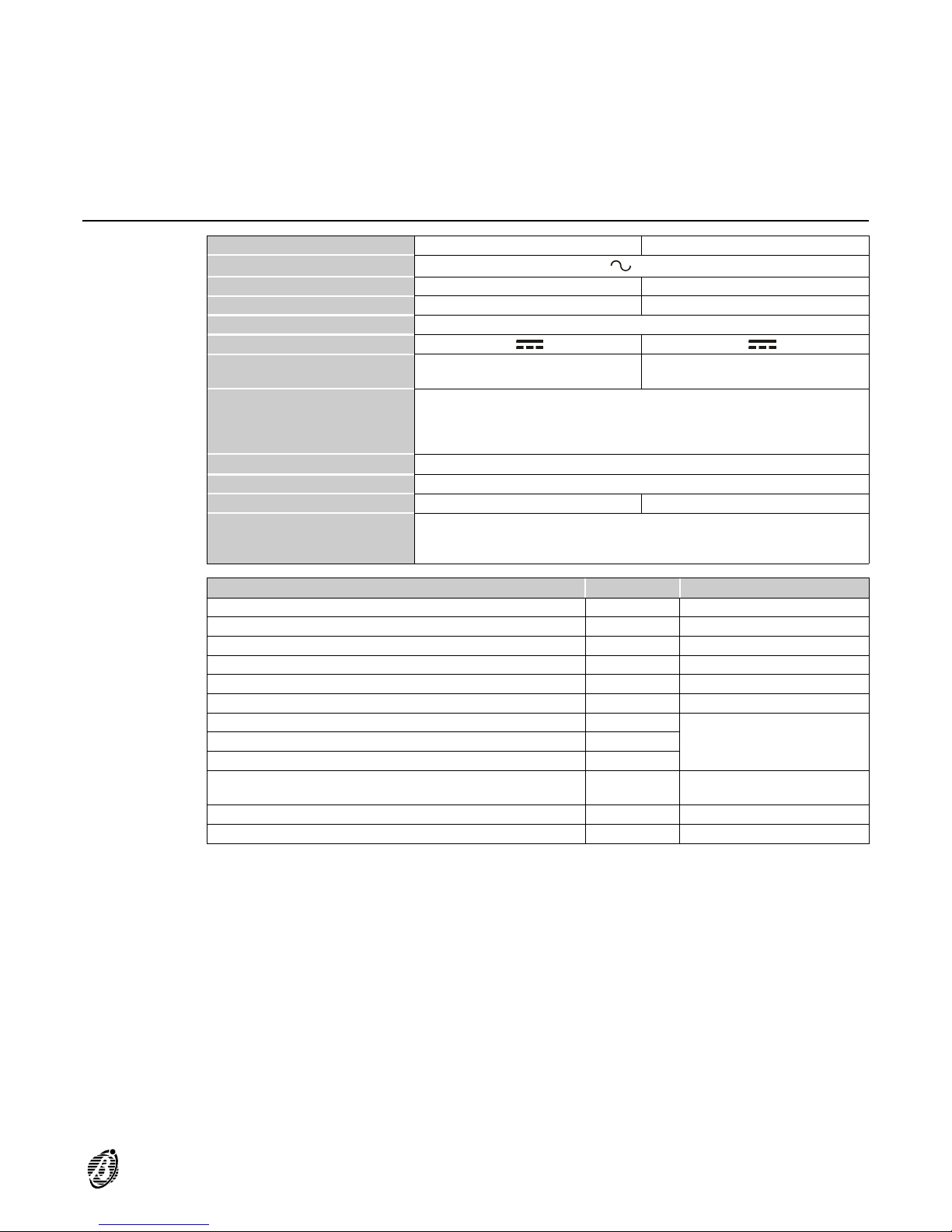
Technical Specifications
Model OMNIA OMNIA/S
Voltage
230 V 50 Hz ±10%
Max. input 0.2 A 0.5 A
Max. power 45 W 115 W
Insulation class
Class
II
Power supply Battery-charger
13.8 V 1.5 A 13.8 V 3 A
Max. current supply to
peripherals
1 A 2 A
Battery
(Make and Model)
12 V - 7 Ah or 12 V - 17 Ah
YUASA
NP 7-12 FR or NP 17-12 FR or
equivalent with UL94-V2 (or over) case flame class
Operating temperature range
5 ÷ 40 °C
Dimensions (W x H x D) 330 x 460 x 100 mm
Weight (without battery) 4.6 Kg 4.2 Kg
Complies with EN standard
EN 50081-1:1992 EN 50130-4:1995 +A1:1998
EN 60950:2000 TBR21:1998
79/2 2
nd
Ed. 1993 - Performance level
IIII
Accessory Item Current Draw Dimensions (WxHxD)
OMNIA/S Main Board 135 mA ----
Keypad (OmniaTAST-R) 50 mA 160 x 73 x 30 mm
Keypad (MIA-S) 50 mA 164 x 132.9 x 43.7 mm
Flush mounting reader (BPI3 / ECLIPSE) 30 mA / 30 mA ----
Wall mounting reader (BPI3W) 30 mA 51 x 73 x 28 mm
Proximity reader (PROXI) 30 mA 77.9 x 108.5 x 22 mm
Input Expander (Omnia4IN / M-IN/6) 15 / 20 mA
108 x 101 x 34 mm
Output Expander (Omnia4OUT / M-OUT/6) 20 / 20 mA
4-relay module (Omnia4R) 120 mA
Voice board + Microphone / Loudspeaker board
(OmniaVOX + VOX-REM )
20 mA ----
Scheduler and Printer interface board (OmniaTIMER) 40 mA ----
Power station (BXM12) 20 mA 234 x 345 x 96 mm
INTRODUCTION 7
Page 8

Accessories
The items with the symbol are tested and approved to European standards.
OMNIA/TAST-R Keypad with backlit LCD (1 input)
MIA/S Keypad with backlit LCD (2 inputs) N.B. This Panel can manage 1 input only.
OMNIA/4IN 4-input expander module
M-IN/6 6-input expander module
OMNIA/4OUT 4-output expander module
OMNIA/6OUT 4-output expander module
M-SUP ---- Expander module holder 108 x101 mm
ASNC Snatch switch (NC)
OMNIA/VOX Voice board
VOX-REM Microphone and loudspeaker for ambient listen-in
MINI-BOX ---- Microphone and loudspeaker box
PROXI ---- Proximity reader
PROXI-CARD ---- Proximity card
ECLIPSE3ABI Flush mounting Contactless reader----AVE version
ECLIPSE3AN Flush mounting Contactless re ade r----AVE noir version
ECLIPSE3DEL Flush mounting Contactlessreade r----DELTA version
ELIPSE3DN Flush mounting Contactlessreader----DELTA noir version
ECLIPSE3GE Flush mounting Contactlessre ade r----GEWISS version
ECLIPSE3GGE Flush mounting Contactlessre ade r----GEWISS noir version
ECLIPSEGP Flush mounting Contactlessre ade r----GEWISS playbus version
ECLIPSE3IN Flush mounting Contactlessreader ----TICINO international version
ECLIPSE3LGT Flush mounting Contactlessre ade r----TICINO light version
ECLIPSE3MA Flush mounting Contactlessreader----TICINO magic version
ECLIPSE3VI Flush mounting Contactless reade r----
VIMAR idea version
ECLIPSE3VIB Flush mounting Contactlessreader ----VIMAR light version
SAT Keyfob for Contactless readers and Proximity readers
BPI3-AVE Flush mounting reader AVE version
BPI3-AN Flush mounting reader AVE noir version
BPI3DEL Flush mounting reader DELTA version
BPI3-DN Flush mounting reader DELTA noir version
BPI3GEW Flush mounting reader GEWISS version
BPI3-GN Flush mounting reader GEWISS noir version
BPI3GP Flush mounting reader GEWISS playbus version
BPI3INT Flush mounting reader TICINO international version
BPI3 Flush mounting reader TICINO magic version
BPI3LGT Flush mounting reader TICINO light version
BPI3LIV Flush mounting reader TICINO living version
BPI3VI Flush mounting reader VIMAR idea version
BPI3VIB Flush mounting reader VIMAR bianco version
BPI3W ---- Wall mounting reader
DKC Keyfob for readers
OMNIA/4R ---- 4-relay module for the output expanders
OMNIA/TIMER Timer programming and printer interface board
B-MOD ---- Teleservice modem
B-MOD/RX ---- Teleservice and remote monitoring modem
CVSER/9F9F ---- Serial cable for computer connection
ADSER/9M25F ---- 25-pin adapter for serial ports
SECURITY SUITE Bentel Security Suite
BXM12/30 3 A remote power-station
BXM12/50 ---- 5 A remote power-station
VECTORBRIDGE-K ---- Universal Wireless Kit
VECTORBPI-K ---- BPI Wireless Kit
8 Expandable Multifunction Control Panel Omnia
Page 9
S
S
P
P
M
M
I
I
C
C
L
L
E
E
D
D
EENN LLOOCC MMIICC
EENN RREEMM MMIICC
B
B
U
U
T
T
T
T
BBLL 222299
S
S
P
P
–
–
S
S
P
P
+
+
+
+
M
M
I
I
C
C
L
L
E
E
D
D
RL1
RL2
RL3
RL4
+12
OC1
OC2
OC3
OC4
AS
1 2 3 4
O
O
m
m
n
n
i
i
a
a
4
4
I
I
N
N
/
/
I
I
N
N
P
P
U
U
T
T
E
E
X
X
P
P
A
A
N
N
D
D
E
E
R
R
M
M
-
-
I
I
N
N
/
/
6
6
O
O
m
m
n
n
i
i
a
a
4
4
O
O
U
U
T
T
/
/
O
O
U
U
T
T
P
P
U
U
T
T
E
E
X
X
P
P
A
A
N
N
D
D
E
E
R
R
M
M
-
-
O
O
U
U
T
T
/
/
6
6
O
O
m
m
n
n
i
i
a
a
4
4
R
R
R
R
E
E
L
L
A
A
Y
Y
M
M
O
O
D
D
U
U
L
L
E
E
4 Prog. Input Zone
Supports up to 16
Supports up to 8
5 A Current Output
B-Mod /Rx:
Teleservice + Telemonitoring
Input Status Enquiry
Appliance Control
Talk/Listen-in facility
Manages serial or par allel Printer
Listen-in facility
8 Indipendent Timers
Records 14 Messages
2Arm and DisA. per day per partition
Telephone dialler
15 year programming period
Answ erph one faci lity
Daily and/or Weekly basis
Supports up to 4
Supp ort s 2
Teleaservice
On board buzzer
17 Ah Battery housing
4 Prog. OC O utput (0.15 A) 4 Relays 250 V - 8 A
Bus BPI
Supports up to 16
B
B
P
P
I
I
3
3
/
/
E
E
C
C
L
L
I
I
P
P
S
S
E
E
/
/
R
R
E
E
A
A
D
D
E
E
R
R
P
P
R
R
O
O
X
X
I
I
Supports up to 16
D
D
K
K
C
C
/
/
S
S
A
A
T
T
/
/
P
P
R
R
O
O
X
X
I
I
M
M
I
I
T
T
Y
Y
K
K
E
E
Y
Y
/
/
C
C
A
A
R
R
D
D
P
P
R
R
O
O
X
X
I
I
-
-
C
C
A
A
R
R
D
D
1 Prog. Input Zone
Supports up t o 8
O
O
m
m
n
n
i
i
a
a
T
T
A
A
S
S
T
T
-
-
R
R
/
/
L
L
C
C
D
D
K
K
E
E
Y
Y
P
P
A
A
D
D
M
M
I
I
A
A
-
-
S
S
4 wire cable
5 wire cable
max. 50 m
123456789
10
2345678910111213
252423222120191817161514
+12V AUX
SPT
PAN
ON
CTS
ER.PAN SER
PPT
PC
OMNIA
1
5
69
Telephone Line
2 prog. Outputs (3 A relays)
2 prog. OC Outputs (1 A relays)
3 A Power Supply
Telephone Communicator
8 prog. Input zones
GRN
BLK
YEL2
YEL
RED
+RC
–
R
–C+
PROG
BPI L.
12 5
5V
1234
ON
Supports up to 4 wireless K eys
Supports up to 31 wi reless
sensors
Cable entry
outlet boxes or similar
Wall or flush mounting to 503
or 1 Speaker
Houses 1 Microphone board
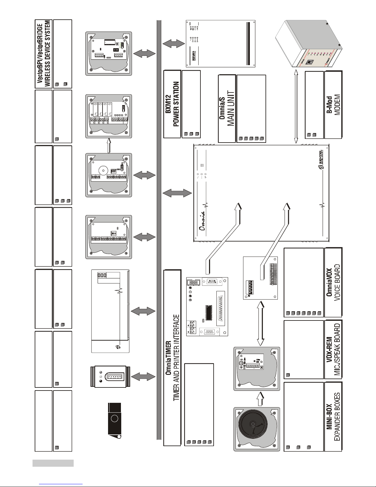
Figure 1 The Omnia system
Page 10
Update
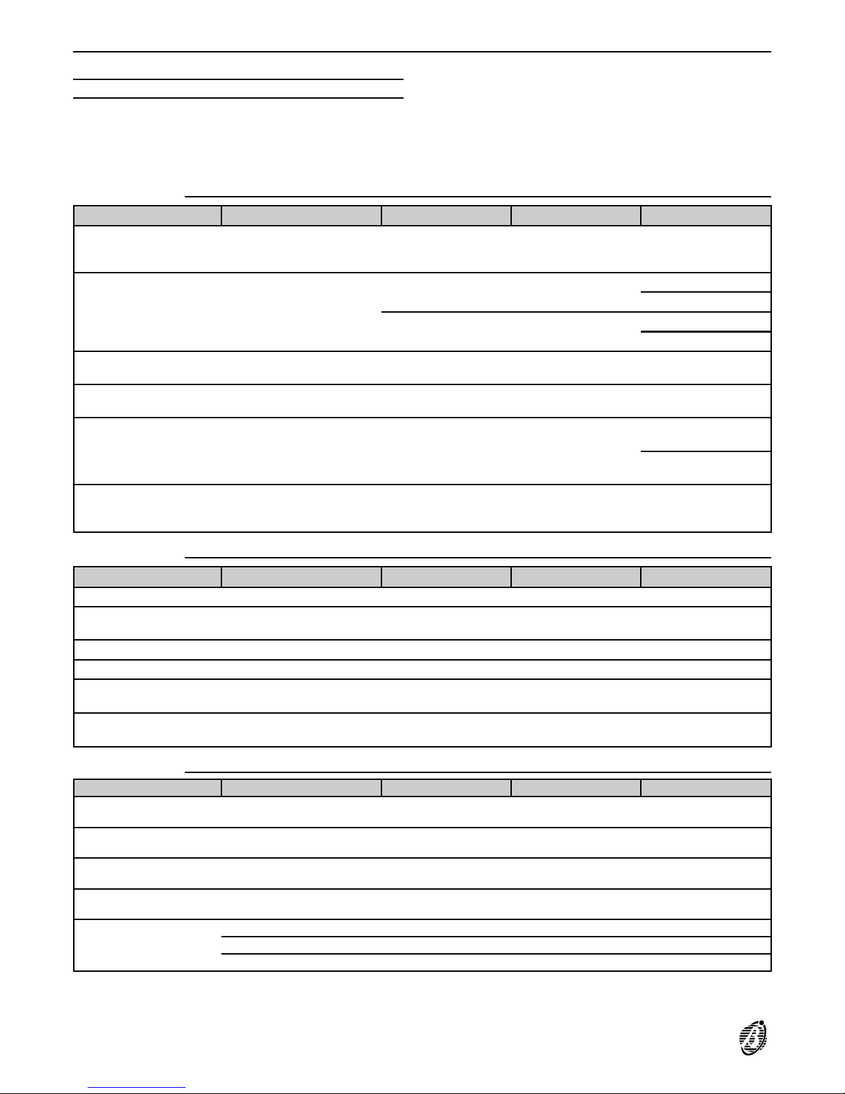
The following tables shows "where to look" for information on the various features of the Omnia Panel types.
SECTION page
Paragraph . . . . . . . . . . . . . . . . . . . . . . . . . page
Sub-paragraph 1 . . . . . . . . . . . . . . . . . . . . . . page
The SUBPARAGRAPH. 2 is as follows:
Subpar. 2 Text.
Omnia 2.1
NEW FEATURES SECTION PARAGRAPH SUBPAR. 1 SUBPAR. 2
Arming inhibited in the
event of remote battery
trouble
PROGRAMMING Options ----
Disable Arming on
battery trouble
Factory default settings
PROGRAMMING
Default ----
Event-Actions
Telephone dialler
A basic system Programming
Telephone numbers
Voice messages
Call queue priority control
PROGRAMMING Event-Actions ----
Priority of telephone
actions
Stop Panel Alarms with
Key/Card
PROGRAMMING Options ----
Enable Stop Panel
alarm with valid key
New events
PROGRAMMING Event-Actions Panel Generic Events
263 - Valid key/card
on panel
361 - Telephone line
trouble
Sends several events
during the same telephone communication
PROGRAMMING Pulse Communicator ---- ----
Omnia 3.0
NEW FEATURES SECTION PARAGRAPH SUBPAR. 1 SUBPAR. 2
Contact ID protocol PROGRAMMING Digital Communicator ---- ----
Contact ID + voice
protocol
PROGRAMMING Digital Communicator ---- ----
No DTMF Communicator ---- ---- ---- ----
Generic event PROGRAMMING Event-Actions Generic events ----
Unsuccessful call telephone numbers
Refer to Security Suite
Manual
Telephone line trouble
logged in buffer
Refer to Security Suite
Manual
---- ----
Omnia 3.1
NEW FEATURES SECTION PARAGRAPH SUBPAR. 1 SUBPAR. 2
The TROUBLE LED also
signal s Zone in Test status
INSTALLATION Zone Attributes Test
"Disable Telephone Line
Check" option
PROGRAMMING Option ----
Disable Telephone Line
Check
"Global Alarm Memory"
event
PROGRAMMING Events-Actions Generic Events on Panel ----
Supports Wireless Devices
PROGRAMMING Configuration Via Radio ----
Supports new BPI peripherals: MIA-S, PROXI,
M-IN/6, M-OUT/6
IDENTIFICATION OF PARTS ---- ---- ----
INSTALLATION Mounting ---- ---INSTALLATION BPI Connections
10 Expandable Multifunction Control Panel Omnia
Page 11
DESCRIPTION OF PARTS
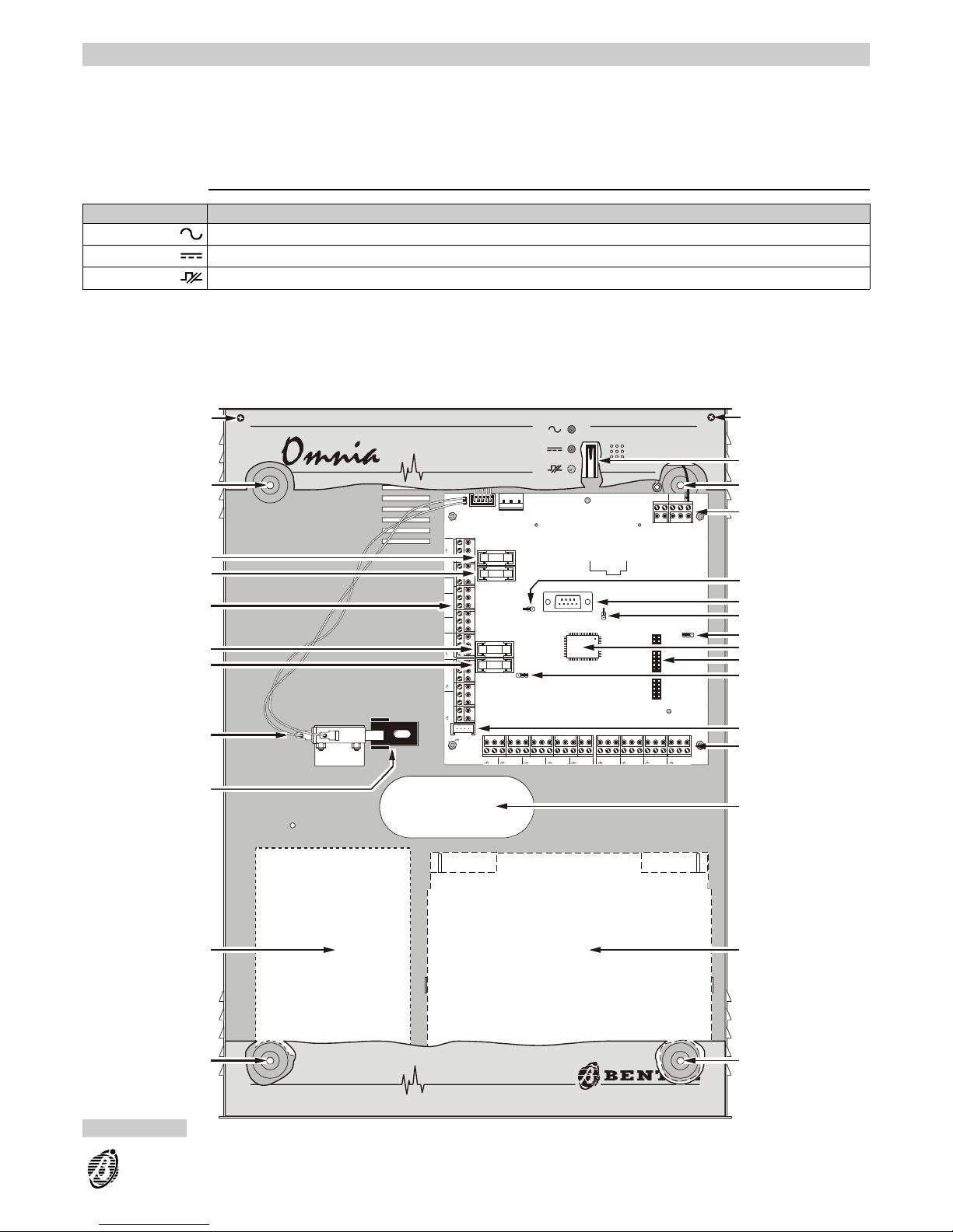
This section describes the main parts of the system, and the meaning of the ON/OFF status of the LEDs.
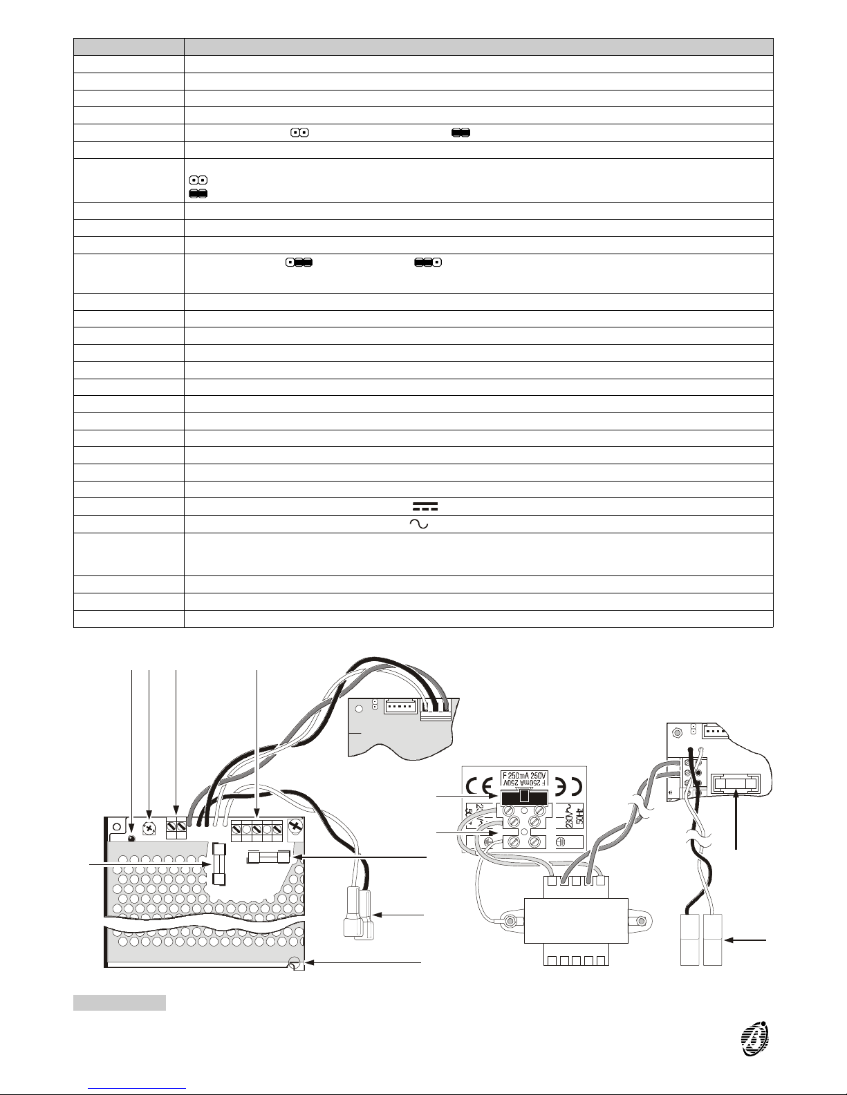
The numbers in boldface (in the Figures) refer to the descriptions in the tables. The white numbers (in the Figures)
refer to the common hardware parts of BPI peripherals, therefore, are not described repeatedly.
Main unit
LED INDICATES
Mains
ON: Mains OK
Battery
ON: battery low or empty
BPI Bus
ON: communication trouble on BPI Bus
1
AC+BNA1NC1C1+A1+N1NA2NC2C2+A2+N2OC1OC2
234567891011121314151617
1818
++CCRR
1919 2020 2121
BPI2BPI1
26 27
ASB
28 29
L1 L2 L3 L4
30
+F +F +F +F
31 32 33 34 35 36 37 38 39 40 41
L5 L6 L7 L8
42
+F +F +F +F
43 44 45 46 47 48 49 50 51
56
LI LE
55 54 53 52
F8A–250V
BATT.+F+B
STOP
ALARM
F3.15A–250V
BPI2
F3.15A–250V
BPI1
12V 5V
BPI–LEV
BPI1
RC+
MEM
+F=F3.15A–250V
+B=F3.15A–250V
FUSES–-
M/B
2/3 1/2
VOX
3
3
15 14
16
4
13
17
12
18
19
10
21
4
8
20
4
7
6
5
3
1
1
3
2
11
9
Figure 2 Main Unit parts
DESCRIPTION OF PARTS 11
Page 12
PART DESCRIPTION
1 Box screws (2)
2 Tamper switch
3 Holes (4) for backplate anchor screws (Ø 5 mm)
4 Terminal boards
5
Stop alarm jumper: > alarm enabled (default); > alarm disabled
6 RS232 serial port
7
Memory Jumper (MEM): will save programmed parameters during blackout
> programmed parameters will be lost (default)
> programmed parameters will be saved
8 Make/Break jumper
9 Microprocessor
10 OmniaVOX board connector
11
BPI Level Jumper > 5 V (at default); > 12V
BPI Level Jumper > 5 V (at default);
12 BPI Keypad connector (OmnaTAST-R or MIA-S)
13 Wire entry
14 Battery housing: 12 V - 17 Ah maximum
15 Power supply section (see Figure 3)
16 Snatch switch bracket
17 Snatch switch
18 Protection fuse for terminal [+] BPI1 Bus (F 3.15A 250V)
19 Protection fuse for terminal [+] BPI2 Bus (F 3.15A 250V)
20 Protection fuse for terminals [+N], [+A] and [+B] (F 3.15A 250V)
21 Protection fuse for terminals [+F] Main unit (F 3.15A 250V)
22 Mains LED
23 Fine adjustment trimmer----output vol tag e
24
External Peripheral power terminals (13.8 V )
25
Mains voltage connection terminals (230 V / 50 Hz)
26
Power supply fuse:
Omnia = F 250 mA 250V
OmniaS = F 2A 250Vfuse
27 Battery plugs
28 Plastic rivet (to be removed when opening the switching-power supply)
29 Battery fuse----protects against polarity inversion (F 8A 250V)
12V 5V
BPI–LEV
12V 5V
BPI–LEV
L
L
N
N
21
AC
3 4
21
+B
AC
23
24 25
29
26
28
27
22
26
25
29
27
Figure 3 Switching Power Supply Units
12 Expandable Multifunction Control Panel Omnia
Page 13
Keypad
ICON MEANING
Partitions armed
Alarm memory
Trouble and Zone in Test status
Not operative with this Panel
Open Panel
Tamper line alarm
Device tamper
False key/card at reader
Device not found
Teleservice enabled
Answering device enabled
Telephone line engaged
PARTS DESCRIPTION
30 Box screws (4)LEDs window
31 LCD
32 Down flip
33 Not available with this Panel
#
345678
0AB
EXC
ESC
12
9
PRGONRES
OFF
2
abc3def
1
5
jkl
64
ghi
8
tuv
9
7
pq
rs
0
A
#
B
C
D
E
S
C
wx
yz
OFFON
1 3 5 72 4 6 8
1 3 5 72 4 6 8
30
31
32 30 30 32 30
30 31
30
a)
b)
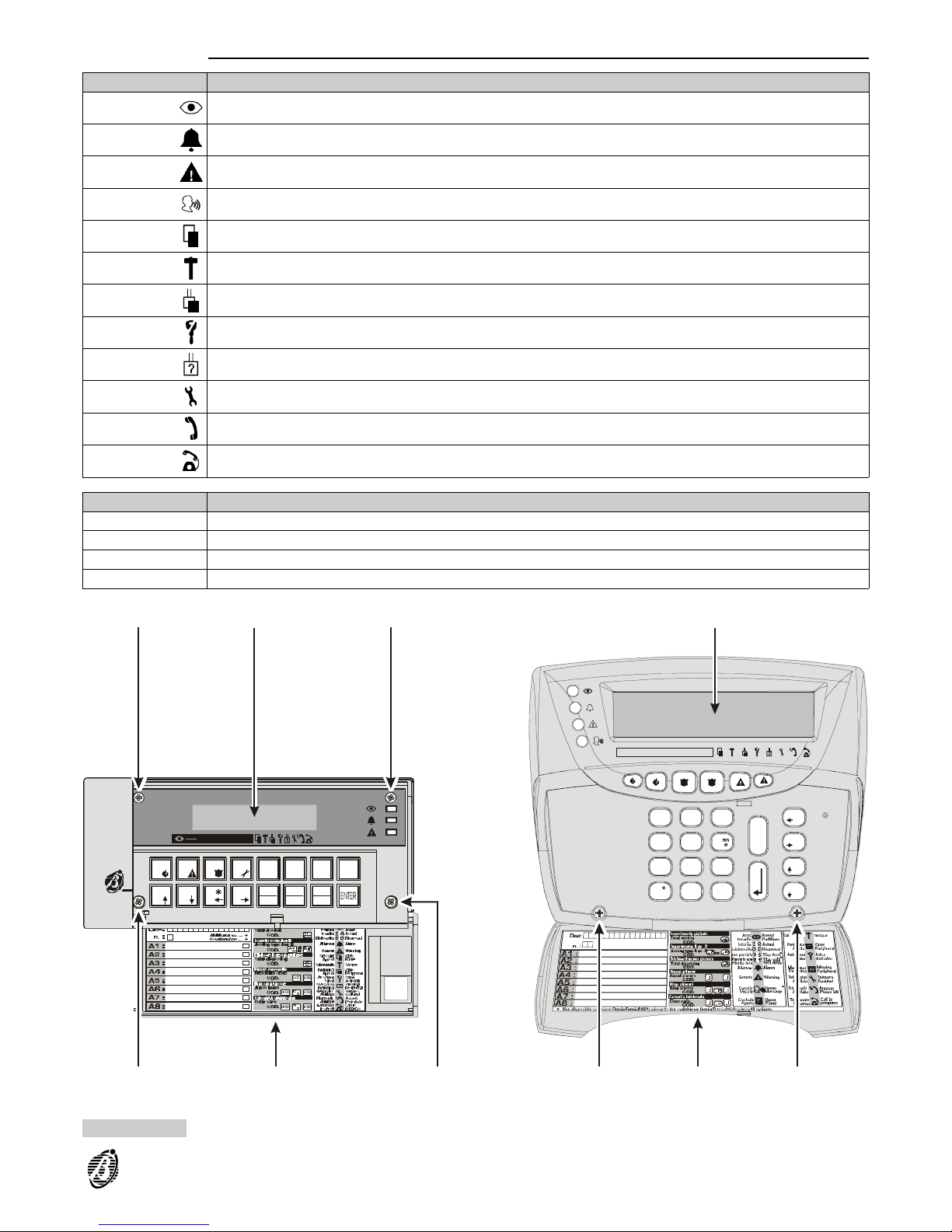
Figure 4 Control Keypad: a)OmniaTAST/R; MIA-S
DESCRIPTION OF PARTS 13
Page 14
PARTS DESCRIPTION
34 Terminal board
35 Tamper switch (2)
36
Snatch switch (accessory item for MIA-S: art. ASNC). The Omnia and Omnia/S Panels comply with IMQ Level
11 certification. MIA-S keypads must be equipped with snatch switches, in order to retain this level.
If MIA-S keypads are not fitted with snatch switches, the Panel will comply with IMQ Level 1 certification.
37 Not available with this Panel
38 Wire entry
39 PCB clips (2)
40a Holes (2) for mounting to mod. 503 outlet boxes or similar
40b Holes (4) for mounting to 10 x 10 outlet boxes or similar
40c Holes (2) for mounting to single gang, 2 gang outlet boxes or similar
41 Hole for snatch bracket anchor screw
42 PCB spacers
43 PCB supports (2)
44 Buzzer
45 Address DIP switches
46 Snatch switch connector
47
BPI Level Jumper: > 5V (at default); > 12V
48 Buzzer connector
49
BPI Level Jumper > 5 V (at default);
BPI Level Jumper > 5 V (at default); > 12V
50 Microprocessor
5V
12V
5V
12V
2
abc3def
1
5
jkl
64
ghi
8
tuv
97
pq
rs
0
A
#
B
C
D
E
S
C
wx
yz
OFFON
21
O
N
34
#
345678
0AB
EXC
ESC
12
9
PRGONRES
OFF
COM NO NC
47
34 35 36 35 38 39 40a
41
40a 39
42
46 45 444838 43 40a4440b 40c39 36 40b 40a 4243
3449
50 35 35 45 42 43 40b 41 40c 40b 43
42
42
a)
b)
49
47
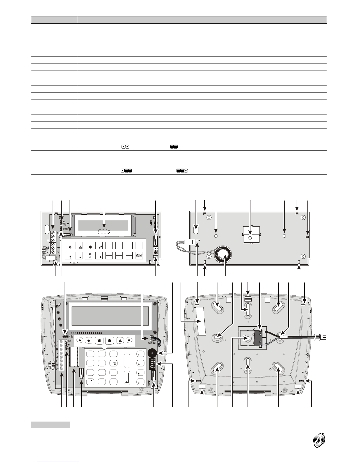
Figure 5 Keypad parts (external view): Omnia TAST/R; MIA-S
14 Expandable Multifunction Control Panel Omnia
Page 15
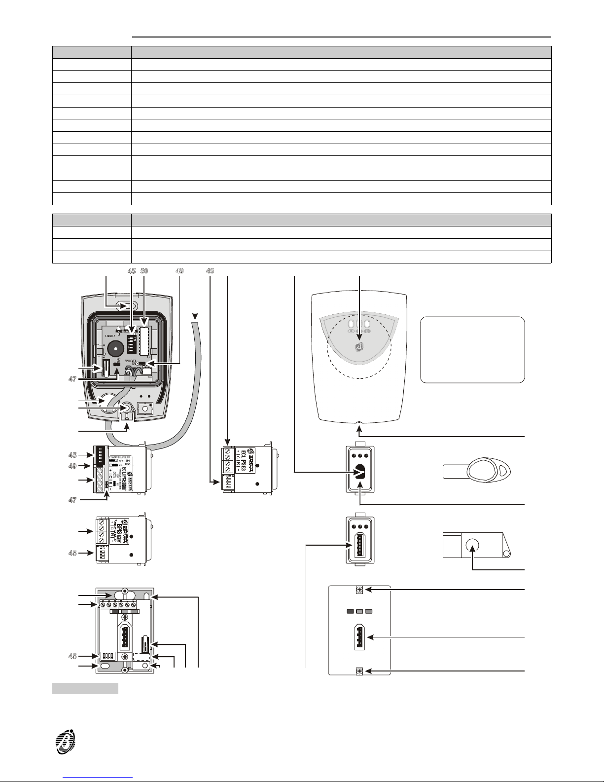
Readers
PARTS DESCRIPTION
51 Anchor screw holes (2)
52 Connection cable: red = +; white = C; blue = R; black = -
53 Terminal board
54 Command button
55 Sensitive field
56 Frontplate Screws
57 Key slot
58 Tamper switch (This system is unable to manage the PROXI reader tamper switch)
59 Snatch switch
60 Snatch bracket hole
61 Cable entry
62 Snap catch
LED MEANING
RED ON: All the Reader partitions are armed
AMBER ON: Type A arming
GREEN ON: Type B arming
–
R
C
5V
+
1
1
1
1
2
2
2
2
3
3
3
3
4
4
4
4
21ON34 21ON34
1234
ON
5
D5.0 BNLDATE3 1.0 201099
60
57
d)
e) f)
g)
h) i)
l)
j)
k)
53
53
61
53
51
59 58 51 57
54
535251
51
61
58
62
54
57
55
56
56
56
a)
b)
c)
Figure 6 Reader Parts: Proximity reader----in ter nal v iew (a) e xternal view (b); Proximity Card (c); Reader----Magic Version,
Contactless, 5 DIP switches----s ide vie w (d) ext ern al vi ew (f); Keyfob for Contactless and Proximity Readers (g);
Reader----Magic Version, with Contacts----side view (h) external view (i); Wall mount Reader----internal view (j) external view (k); Keyfob for Readers with contacts (l)
DESCRIPTION OF PARTS 15
Page 16
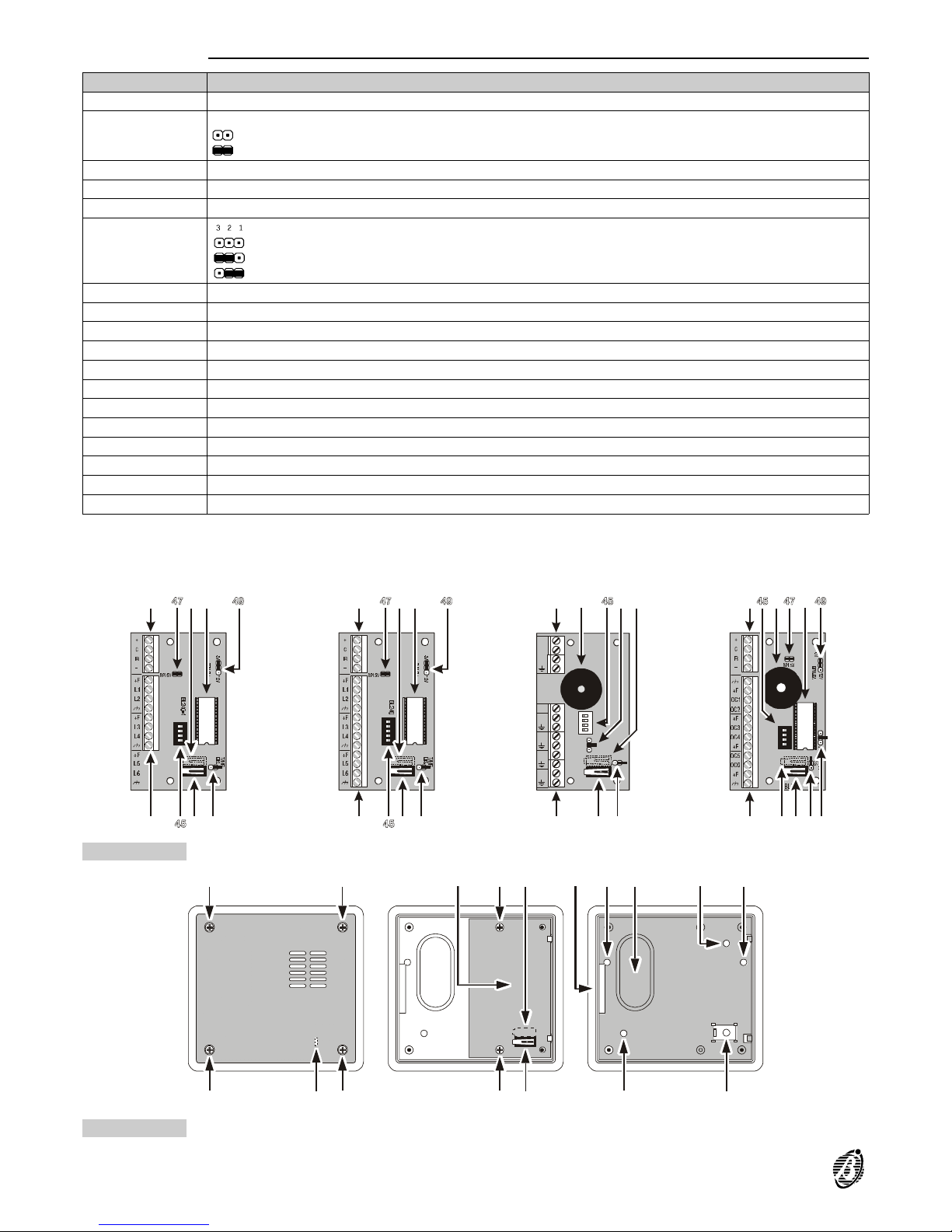
Input and Output expanders
PART DESCRIPTION
63 Terminal board for BPI bus
64
Tamper and Snatch bypass jumper:
> switches unbypassed
> switches bypassed (default)
65 Snatch switch
66 Microprocessor
67 Buzzer
68
Buzzer mode jumper:
>buzzer bypassed (at default)
>buzzer will be activated when terminal [OC4] opens
>buzzer will be activated when terminal [OC4] connects to negative
69 Tamper switch
70 Terminal board
71 Not available with this Panel
72 Box screws (4)
73 Input or Output expander or 4 relay Module
74 Expander screws (2)
75 Cable entry
76 Holes (2) for mounting to mod. 503 outlet box or similar
77 Cable duct entry
78 Wall mounting anchor screw holes (2)
79 Snatch bracket anchor screw hole
80 Plastic tooth (closes tamper switch)
1
1
2
2
3
3
4
4
+
12V
C
OC4
OC3
OC2
OC1
R
1
1
2
2
3
3
1234
ON
5
1234
ON
1
1234
ON
63 65 66 63 67 68 65 63 67 66
70 69 64 70 69 64 70 69 646865
b)
c)
d)
63 65 66
70 69 64
a)
Figure 7 Input/Output Expander Parts: Omnia4IN (a) M-IN/6 (b) Omnia4OUT (a) M-OUT/6 (b)
72 72
73
74 65 75
797874
80
72 72 69
78
77
76 76
Figure 8 Module and Expander Box
16 Expandable Multifunction Control Panel Omnia
Page 17
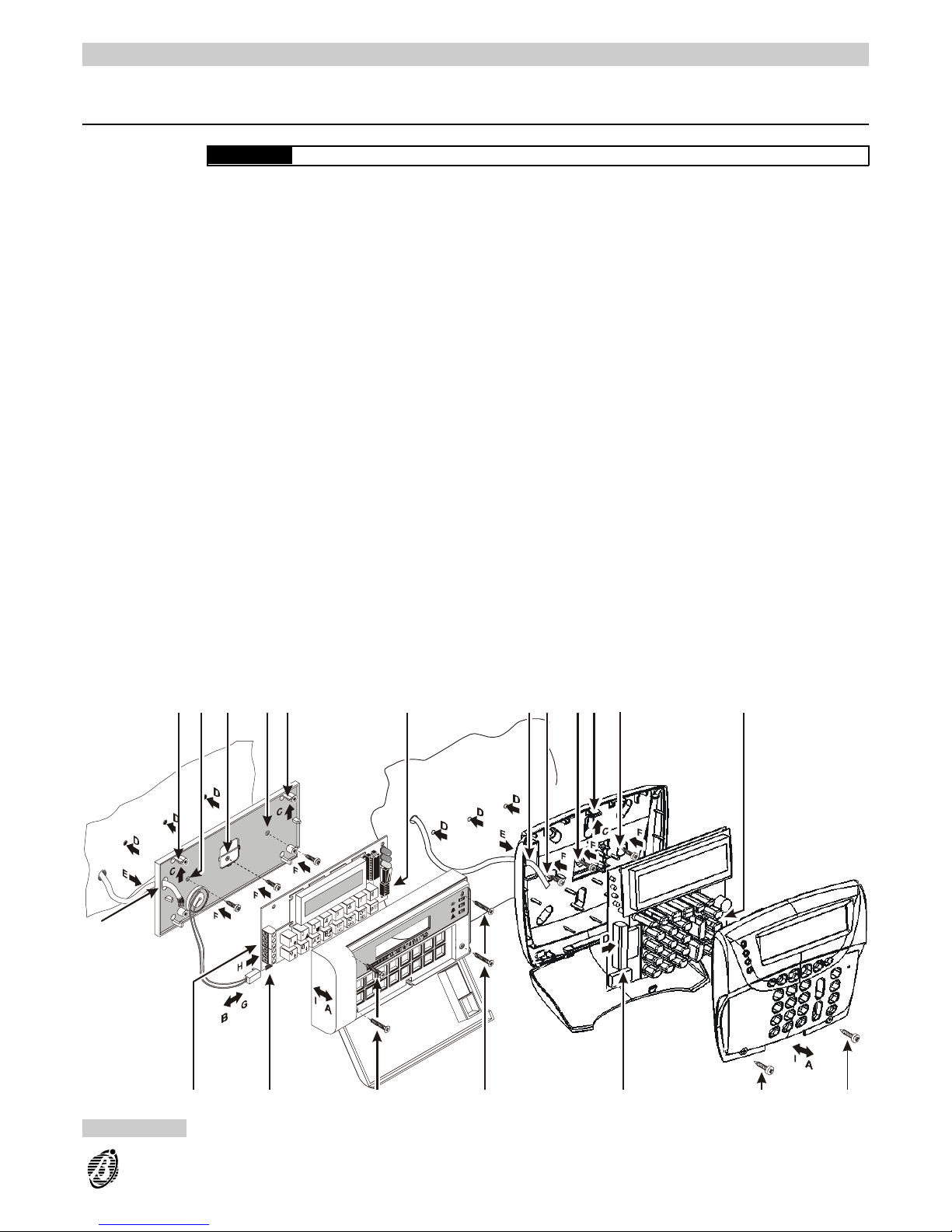
INSTALLATION
Mounting the Panel
The Panel must be located in a safe place.
IMPORTANT The Panel must be at least 2 metres from GSM and radio relay systems.
Step 1 Create a layout----include all alarm detection peripherals, zone expanders, keypads, readers, etc.
Step 2 Drill the holes for the cabinet 13 and snatch bracket 14 (see Figure 2----Parts).
Step 3 Pull the connection wires through the hole 11 (see Figure 2----Parts) then attach the cabinet and snatch bracket to
the wall.
+
Do not over tighten the snatch bracket screw as this may damage the bracket.
Step 4 Install additional modules and boards (Omnia4IN, M-IN/6, Omnia4OUT, M-OUT6, OmniaVOX, OmniaTIMER,
etc.----refer to the relevant instructions).
Step 5 Complete the connections----do not connect the Mains until all other wiring is complete.
Step 6 Set the BPI Level (refer to BPI Level in the Connecting BPI Peripherals section for instructions).
Step 7 Connect the power supply (refer to the Connecting the Power Supply section for instructions).
Step 8 Program the Panel (refer to the PROGRAMMING section for instructions).
Mounting the
keypad
The keypad should be located in a place where full control of the security system is required. OmniaTAST-R and
MIA-S keypads can be either wall mounted, or mounted to mod. 503 outlet boxes or similar. MIA-S keypads can
be mounted to 10 x 10 Single or Double Gang outlet boxes.
Step 1 Remove the screws 30 and the frontplate.
Step 2 Disconnect the buzzer connector 44 (for OmniaTAST -R keypads only).
Step 3 Push the board supports 39 upwards and release the PCB.
Step 4 Drill the holes for the backplate and snatch bracket anchor screw (40a and 41 respectively). If necessary, fit the
Snatch switch 36 (for MIA-S keypads only).
+
The Snatch switch cannot be fitted when the MIA-S keypad is fitted to an outlet box.
Step 5 Pull the connection wires through the hole 38 then attach the backplate and snatch bracket to the wall.
38
30 30
48
39 40a 41 40a 39 45
34
38 40a 41 39 40a 45
34 30 30
a) b)
Figure 9 Installing the keypad: Omnia TAST (a); MIA-S keypad (b)
INSTALLATION 17
Page 18
Step 6 Replace the PCB then connect the buzzer 44 to connector 48 (for OmniaTAST-R keypads only). If fitted, connect
the Snatch switch to connector 46 (for MIA-S keypads only).
Step 7 Assign the keypad Address, set the BPI Level (for MIA-S and OmniaTAST-R) , then complete the connections on
the terminal board 34 (refer to the Connecting BPI Peripherals section for instructions).
Step 8 Reattach the frontplate.
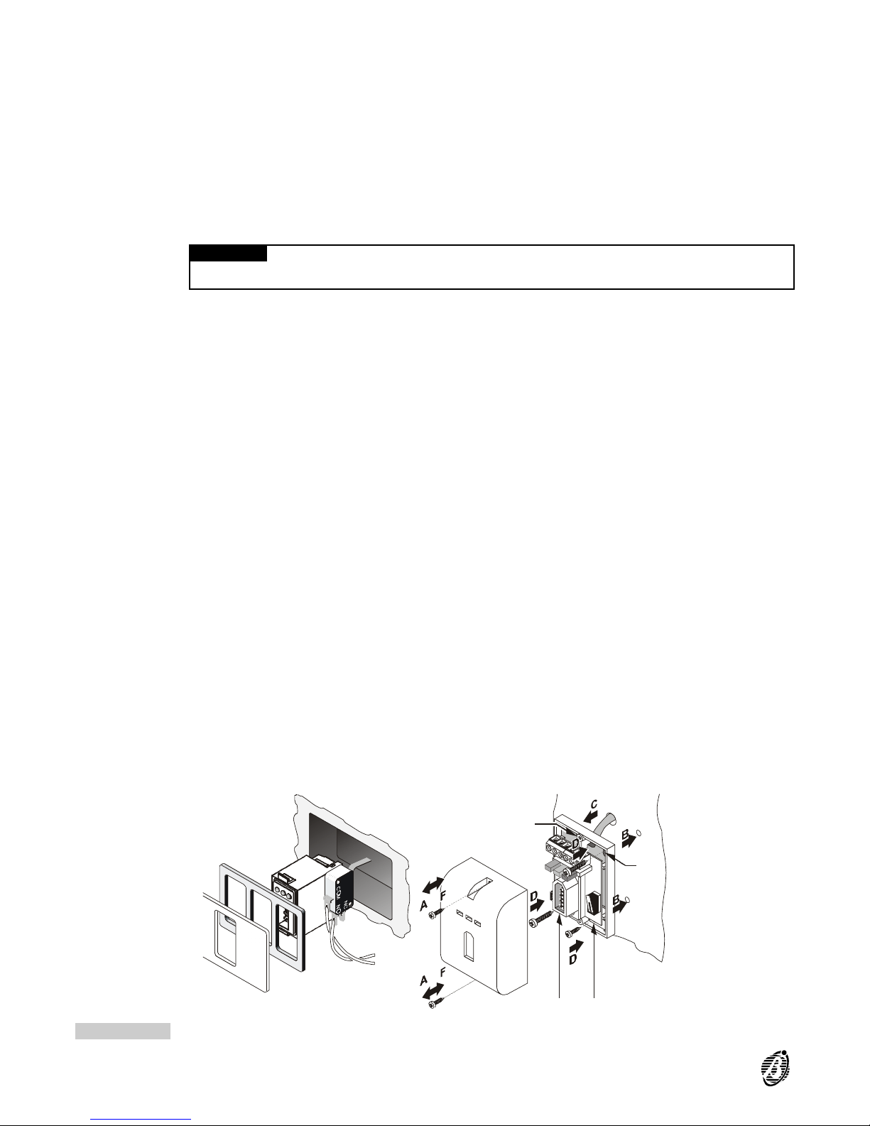
Flush mounting
Reader
Readers can be located in places where limited control of the security system is required.
Step 1 Assign the keypad Address, set the BPI Level (for ECLIPSE Readers only) then complete the connections on the
terminal board 53 (refer to the Connecting BPI Peripherals section for instructions).
Step 2 Install the reader as per Figure 10a.
IMPORTANT In order to comply with the Security System Regulations in force, ensure that Flush mounting
readers, located outdoors, are equipped with tamper protection (see Figure 10a).
ECLIPSE readers must be at least 10 cm apart.
BPI3W Wall
mounting and
PROXI readers
The operating principles of BPI3W and PROXI readers are the same, both devices are designed for wall mounting
and do not require outlet boxes.
PROXI readers are equipped with weather-strips (Protection Class IP34), and are suitable for outdoor use.
+
Proximity readers must be at least 50 cm apart.
Step 1 For BPI3W readers: remove the screws 56 and the frontplate.
For PROXI readers: remove the screw 56, then using a screwdriver or similar tool, push the snap catch 62free to
release the frontplate.
Step 2 Drill the holes for the backplate 51 and snatch bracket 60 anchor screws (for BPI3W only).
Step 3 Pull the wires through the cable entry 61 (for BPI3W only) then attach the backplate and snatch bracket (for
BPI3W only) to the wall.
Step 4 Assign the reader Address, set the BPI Level (for PROXI Readers only), then complete the connections (refer to
the Connecting BPI Peripherals section for instructions).
Step 5 Reattach the frontplate.
Expanders and
Relay modules
The Input expanders, Output expanders and Relay modules must be mounted close to the devices they are connected to.
Step 1 Remove the screws 72 and front.
Step 2 Remove the screws 74 and PCB.
Step 3 Remove the knockout (75 or 77 as required).
Step 4 Wall mounting: drill the holes for the backplate and snatch bracket anchor screws (78 and 79 respectively----see
Figure 11b).
Mounting on Mod. 503 outlet box or similar: drill the hole for the snatch bracket screw only (see Figure 11c).
----No drilling is necessary for Flush mounting (Figure 11a).
Step 5 Pull the connection wires through the wire entry then attach the backplate and snatch bracket.
+
Position the snatch switch as per Figure 11----for Wall and Flush mounting.
Figure 10 Flush mounting reader (a); Wall mounting reader (b)
18 Expandable Multifunction Control Panel Omnia
Page 19
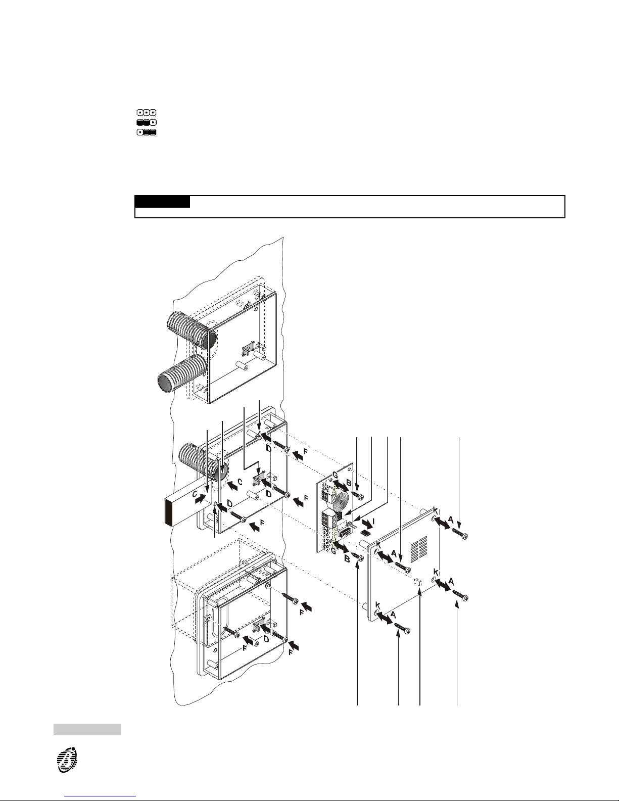
Step 6 Replace the PCB.
Step 7 Assign the expander Address, set the BPI Level (for M-IN/6 and M-OUT/6 only), then complete the connections on
the terminal board 63 (refer to the Connecting BPI Peripherals section for instructions).
Step 8 Remove the jumper 64 to enable the tamper and snatch switches.
Step 9 Using the jumper 68, set the Output-expander buzzer mode.
>buzzer bypassed (at default)
>buzzer will be activated when terminal [OC4] opens
>buzzer will be activated when terminal [OC4] closes to negative
Step 10 Close the box.
+
Ensure that the tamper switch 69 is closed properly by the plastic tooth 80.
The Input and Output expanders and the Relay module can be installed inside the Panel (see Figure 12) by means
of supports (optional).
IMPORTANT The Tamper and Snatch switches (attached by means of supports) of Input and Output expander
must be disabled (jumper 64 connected).
74
72
724574 64
75
77
79
78
78
a)
b)
c)
80 72
72
Figure 11 Expander installation: (a) Flush mounting; (b) on view; (c) inside mod.503 box
INSTALLATION 19
Page 20
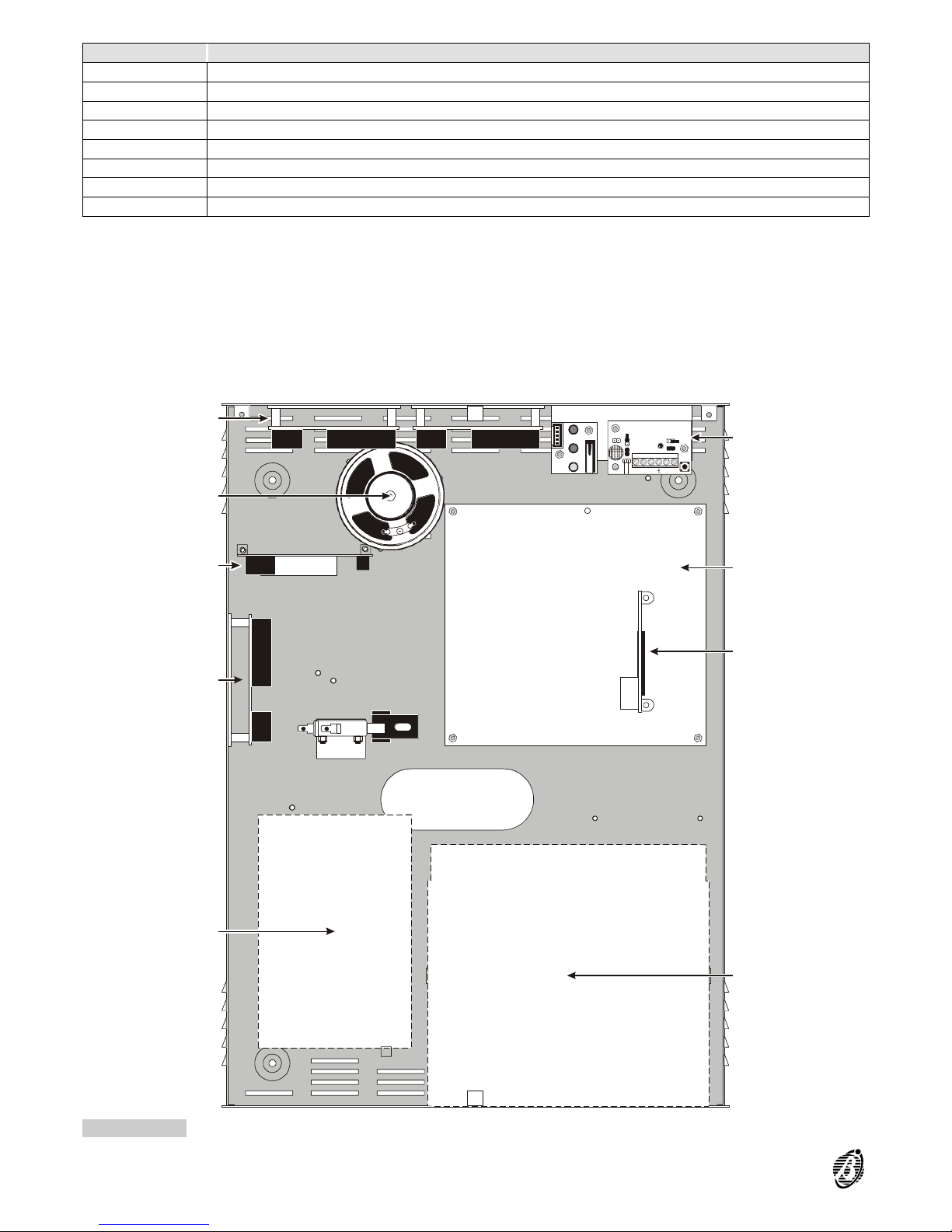
PART DESCRIPTION
81 Microphone board (VOX-REM)
82 Main board
83 Voice board (OmniaVOX)
84 Battery 12 V - 17 Ah maximum
85 Power Supply Unit
86 Expanders (Omnia4IN, M-IN/6, Omnia4OUT, M-IN/6, Omnia4R): maximum 3
87 Printer Interface - Scheduler (OmniaTIMER)
88 Speaker
S
S
P
P
M
M
I
I
C
C
L
L
E
E
D
D
EENN LLOOCC MMIICC
EENN RREEMM MMIICC
B
B
U
U
T
T
T
T
BBLL222299
S
S
P
P
–
–
S
S
P
P
+
+
+
+
M
M
I
I
C
C
L
L
E
E
D
D
86
88
87
86
85
81
82
83
84
Figure 12 Maximum configuration
20 Expandable Multifunction Control Panel Omnia
Page 21

The Terminal board
Following is the description of the Panel and BPI peripheral terminals.
The TERMINAL column shows the terminal identifier (in square brackets):
---- not present means the terminal is not available on the Panel in question.
The DESCRIPTION column provides a brief description of each terminal.
The v(V) column shows the voltage of the terminals (the "----" symbol means the voltage cannot be specified).
The i(A) column shows the maximum current (in amperes) that can circulate on each terminal (the "----" symbol
means that the voltage cannot be specified).
+
The numbers in round brackets refer to the following notes.
(1) The total current draw of Panel terminals [+F], [+B], [+], [+A] and [+N] should not exceed:
---- 2 A for Omnia/S
---- 1 A for Omnia
(2) 13.8 V is present on the [+] terminals of the Panel----protected by fuse 18 for the BPI1----and fuse 19 for BPI2. This
voltage will be supplied by the battery in the event of Mains failure.
(3) The total current draw of the [+] terminals of BPI peripherals is as follows:
---- Keypad = 50 mA
---- Reader = 30 mA
---- Input expander = 15 mA
---- Output expander = 20 mA
---- Power station = 20 mA
These values refer to the current draw with no load (no peripherals).
(4) The total current draw of the [+F] terminals of Input expanders should not exceed 0.4 A.
The Panel
TERMINAL DESCRIPTION v(V) i(A)
[AC]
Connected terminals
(not present in the model with switching power-supply)
---- ----
[+B]
Voltage to peripherals----protected by fuse 20
This voltage is supplied by the battery during Mains failure
13.8 (1)
[]
Ground 0 ----
[NA1-NC1-C1]
RL1 output (voltage free relay switch):
standby C1 connected to NC1----NA1 open
alarm C1 connected to NA1----NC 1 open
---- 3
[+A1]
RL1 programmable output (positive):
standby terminal open
alarm voltage on terminal
13.8 (1)
[+N1]
RL1 programmable output (intrinsic security):
standby voltage on terminal
alarm terminal open
13.8 (1)
[NA2-NC2-C2]
RL2 programmable output (voltage free relay switch):
standby C2 connected to NC2----NA2 open
alarm C2 connected to NA2----NC 2 open
---- 3
[+A2]
RL2 programmable output (positive):
standby terminal open
alarm voltage on terminal
13.8 (1)
[+N2]
RL2 programmable output (intrinsic security):
standby voltage on terminal
alarm terminal open
13.8 (1)
[OC1] Programmable open-collector output 0 1
[OC2] Programmable open-collector output 0 1
[+] [C] [R] [ ]
No.2 BPI Bus (BPI1 and BPI2) for BPI peripherals (LCD Keypads, Input Exp., Output Exp., Readers) (2) (1)
[ASB]
Balanced tamper line (terminal [ASB]) normally connected to ground (terminal [] by a 10K resistor
---- ----
[L1
…… L8] Programmable input lines ---- ----
[+F]
Voltage for sensors----protected by fuse 21
supplied by the battery during mains failure
13.8 (1)
[]
Earth terminal 0 ----
[LE] Terminal for PSTN line connection ---- ----
[LI] Terminal for the connection of line-sharing devices (answerphone, telephone, fax machines, modems, etc.) ---- ----
INSTALLATION 21
Page 22
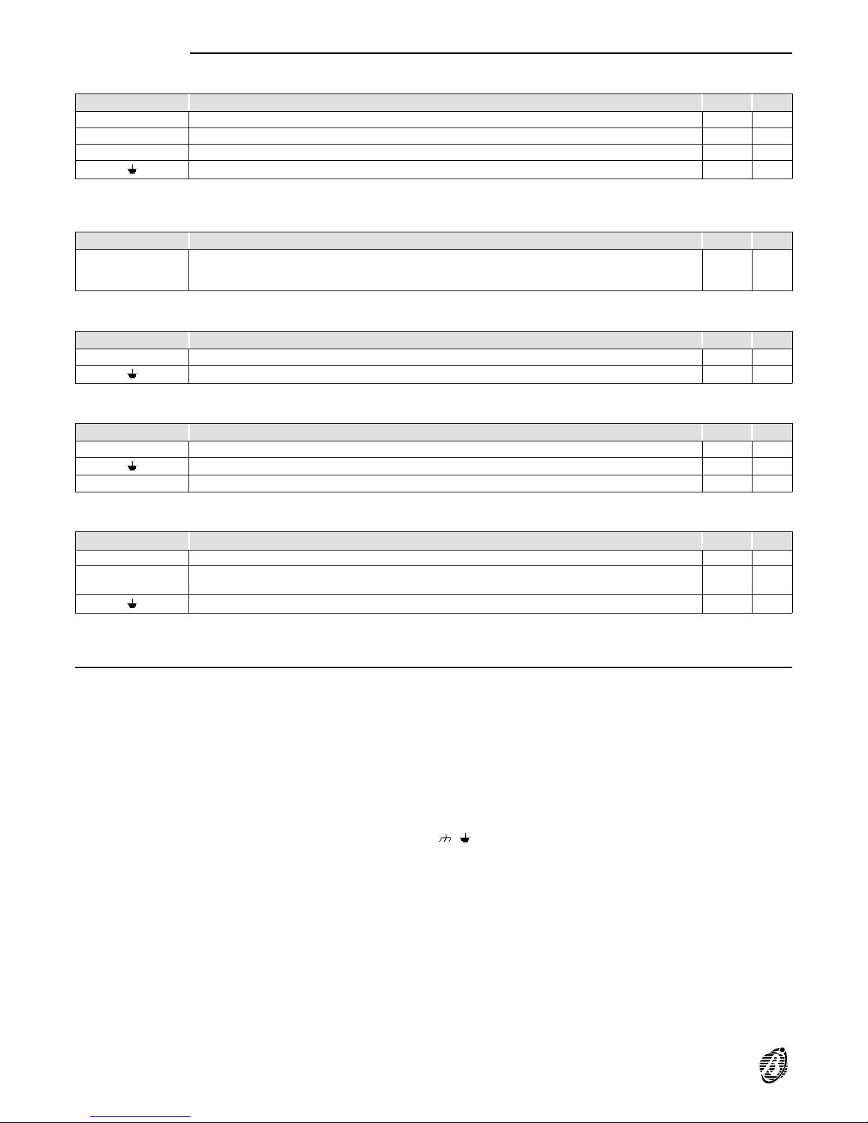
BPI Peripherals
The following table describes the device terminals. The terminals are the same for all BPI peripherals----LCD
Keypads, Readers, Input expanders, Output expanders and Power stations.
TERMINAL DESCRIPTION v(V) i(A)
[+] Voltage: positive 13.8 (5)
[R] "Answer" terminal to be connected to the corresponding terminal on the Panel ---- ----
[C] "Command’’ terminal to be connected to the corresponding terminal on the Panel ---- ----
[]
Voltage: negative 0 ----
Reader Flush mounting readers have Bus connection terminals only.
Wall mounting readers have also the following terminals:
TERMINAL DESCRIPTION v(V) i(A)
[AS]
Tamper switch:
closed when switches 58 and 59 are closed
open when switch 58 or 59 is open
---- ----
Keypad The keypad has Bus connection terminals, and also the following:
TERMINAL DESCRIPTION v(V) i(A)
[L1] Programmable input line ---- ----
[]
Input-line ground 0 ----
Input expander Input expanders have Bus connection terminals, and also the following:
TERMINAL DESCRIPTION v(V) i(A)
[L1] [L2] [L3] [L4] Programmable input lines ---- ----
[]
Input-line ground 0 ----
[+F] Sensor supply protected by resettable fuse 13.8 (6)
Output expander Output expanders have Bus connection terminals, and also the following:
TERMINAL DESCRIPTION V I
[+12V] Voltage for peripherals connected to open-collector outputs, protected by resettable fuse 13.8 0.4
[OC1] [OC2]
[OC3] [OC4]
Programmable open-collector outputs 0 0.15
[]
Ground terminals 0 ----
Power station Refer to the instructions provided with the Power station.
Schematic diagrams
The schematic diagrams and instructions refer to the connections of the various BPI devices (Keypads, Readers,
etc.).
The different device connections (BPI devices, Sensors, Signalling devices, etc.) are illustrated separately.
+
Use shielded cable only for the connections, with one end connected to negative, and the other floating.
Following are just a few of the many solutions this Panel provides.
Diagram symbols The schematic diagrams may differ slightly from the board.
The input zone and open-collector-output terminals----shown in the diagrams----can be found on the Panel and on
the expanders.
Each schematic diagram shows the relevant terminals only.
+
The negative terminals may be represented by , or --.
22 Expandable Multifunction Control Panel Omnia
Page 23
Connecting BPI Peripherals
The BPI Bus supports the following peripherals:
Up to 8 Keypads
Up to 16 Key/Card Readers
Up to 16 Input Expanders
Up to 8 Output Expanders
2 power stations
Electrical
connections
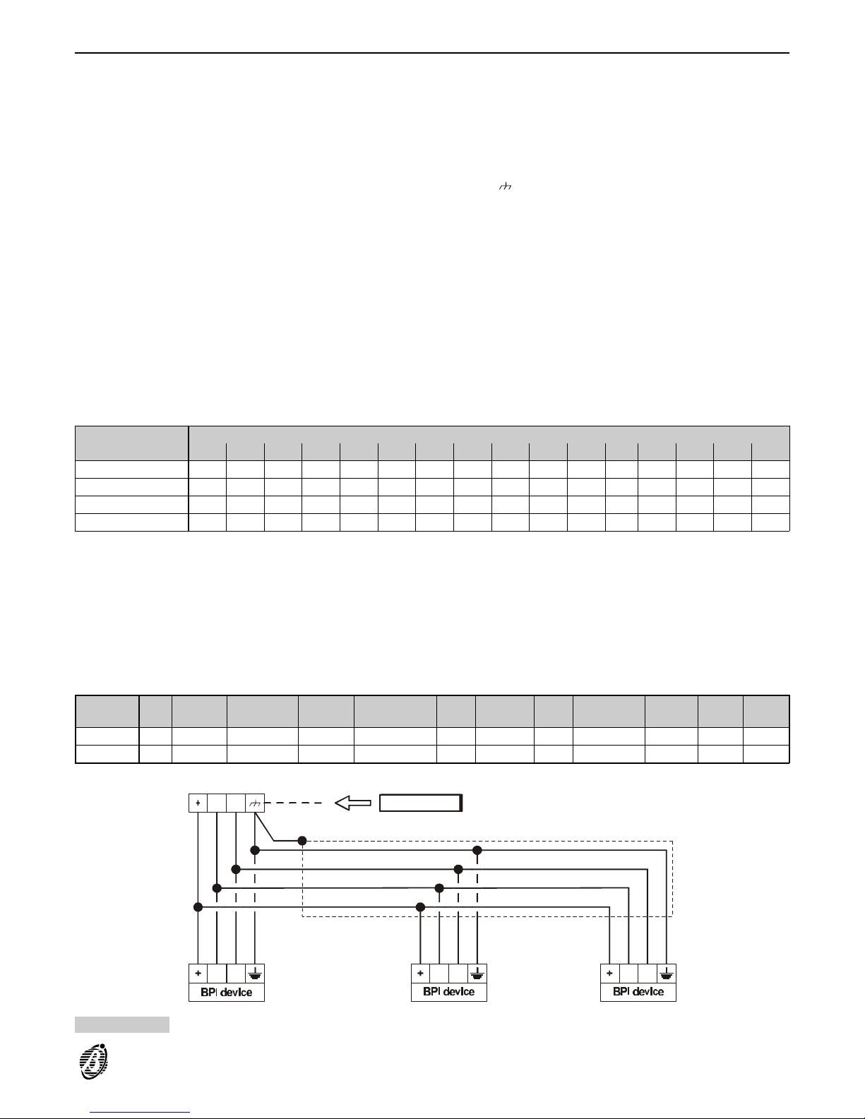
The BPI s must be connected to terminals [+], [C], [R] and [ ], as per Figure 13.
Split Section
BPI Bus
The Omnia and Omnia/S BPI Bus has two independent sections----one consisting of terminals 22, 23, 24 and 25
and the other of terminals 18, 19, 20 and 21. Each section has its own protection fuse, and trouble circuit therefore, trouble on one section will not impair the other.
The outdoor BPI peripherals should be connected to one section of the BPI Bus, and the indoor BPI peripherals
to the other; in this way, tamper on the outdoor BPI peripherals will be signalled on the Panel but will not interfere
with the operating capacity of the indoor BPI peripherals.
Figure 13 illustrates the connection of 3 BPI peripherals (Keypads, Readers, Input expanders, Output expanders
or Power stations).
Assigning
Addresses
The BPI peripheral addresses can be assigned via the DIP switches 45, as shown in the following Table, the numbers in brackets in the DIP switch column refer to the DIP switches that must be used when assigning Addresses
to BPI peripherals with 5 switches (ECLIPSE with 5 DIP Switch strip, PROXI, M-IN/6, M-OUT/6)
Power station Refer to the instructions provided with the Power station.
DIP Switch No.
Address
12345678910111213141516
1 (2) off off off off off off off off ON ON ON ON ON ON ON ON
2 (3) off off off off ON ON ON ON off off off off ON ON ON ON
3 (4) off off ON ON off off ON ON off off ON ON off off ON ON
4 (5) off ON off ON off ON off ON off ON off ON off ON off ON
+
Addresses can be assigned in any order, however, peripherals of the same type must have different addresses----refer to Assigning Addresses.
Peripherals of different types (e.g. a keypad and expander) can have the same address, as these devices are
intrinsically different for the Panel. The BPI Bus supports up to 8 keypads and 8 output expanders, switch no. 1
(and switch no. 2 for devices with 5 Switch DIP strips) is ineffective for these devices.
BPI Level The BPI Level is the maximum voltage that the BPI Bus can carry.
+
The BPI Level of the peripherals must match the BPI Level of the Bus.
All BPI peripherals are compatible with a 5V BPI Level, however, some are also compatible with a 12V BPI Level,
as shown in the following table.
BPI Level BPI3 ECLIPSE ECLIPSE5m PROXI
OmniaTAST-R
MIA-S Omnia4IN M-IN/6 Omnia4OUT M-OUT/6 Vector BXM12
5 V YES YES YES YES YES YES YES YES YES YES YES YES
12 V no no YES YES YES YES YES YES no YES YES no
CR RRCCC
C
R
Main unit
Figure 13 Connectiing BPI peripherals to the BPI Bus
INSTALLATION 23
Page 24
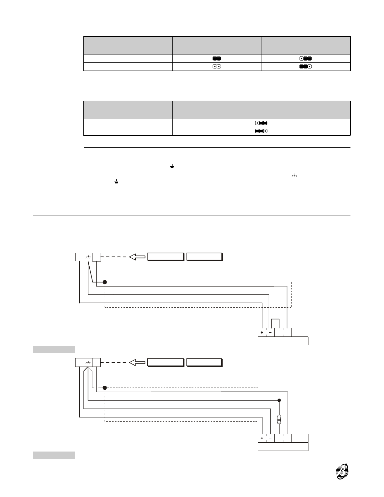
+
The BPI Bus cannot function properly at 12V unless all the BPI peripherals support this standard.
The BPI Level can be set by means of jumpers 47 and 49, as shown in the following table.
BPI Level
Jumper 47
Jumper 49
5
12
Refer to the VectorBRIDGE and VectorBPI Installation Manuals for the BPI Level of wireless devices.
The Omnia/S supports 5V and 12V BPI Level standards. The BPI Level of Omnia/S can be set by means of
jumper 11, as shown in the following table.
BPI Level
BPI Level
5
12
BPI Bus wiring limitations
The BPI Bus peripherals must be within 500 meters (in wire length) of the Panel.
+
The overall wire length for each section of the BPI Bus can be no more than 1,000 meters.
If the voltage across terminals [+] and [ ] is less than 11.5 V (the voltage required by the BPI peripherals) you can:
increase the supply wire section to the device (the wires that connect terminals [+] and [ ] of the Panel to termi-
nals [+] and [ ] of the device);
connect a power station to boost the voltage;
connect a power station to supply the BPI peripherals loads.
Connecting Alarm sensors
The Panel provides 8 zones on the Main board; 4 Zones per Input Expander; and 1 Zone per Keypad (for alarm
sensors).
The Panel can manage up to 80 zones.
The input zone terminals are marked [L1], [L2], etc.
5V
12V
5V
12V
sensor
N. C. A.
L1+F
S.
Main unit Input exp.
Figure 14 Connecting a Sensor to Normally Closed line
10K
sensor
N. C. A.
L1+F
S.
Main unit Input exp.
Figure 15 Connecting a Sensor to a Balanced line
24 Expandable Multifunction Control Panel Omnia
Page 25
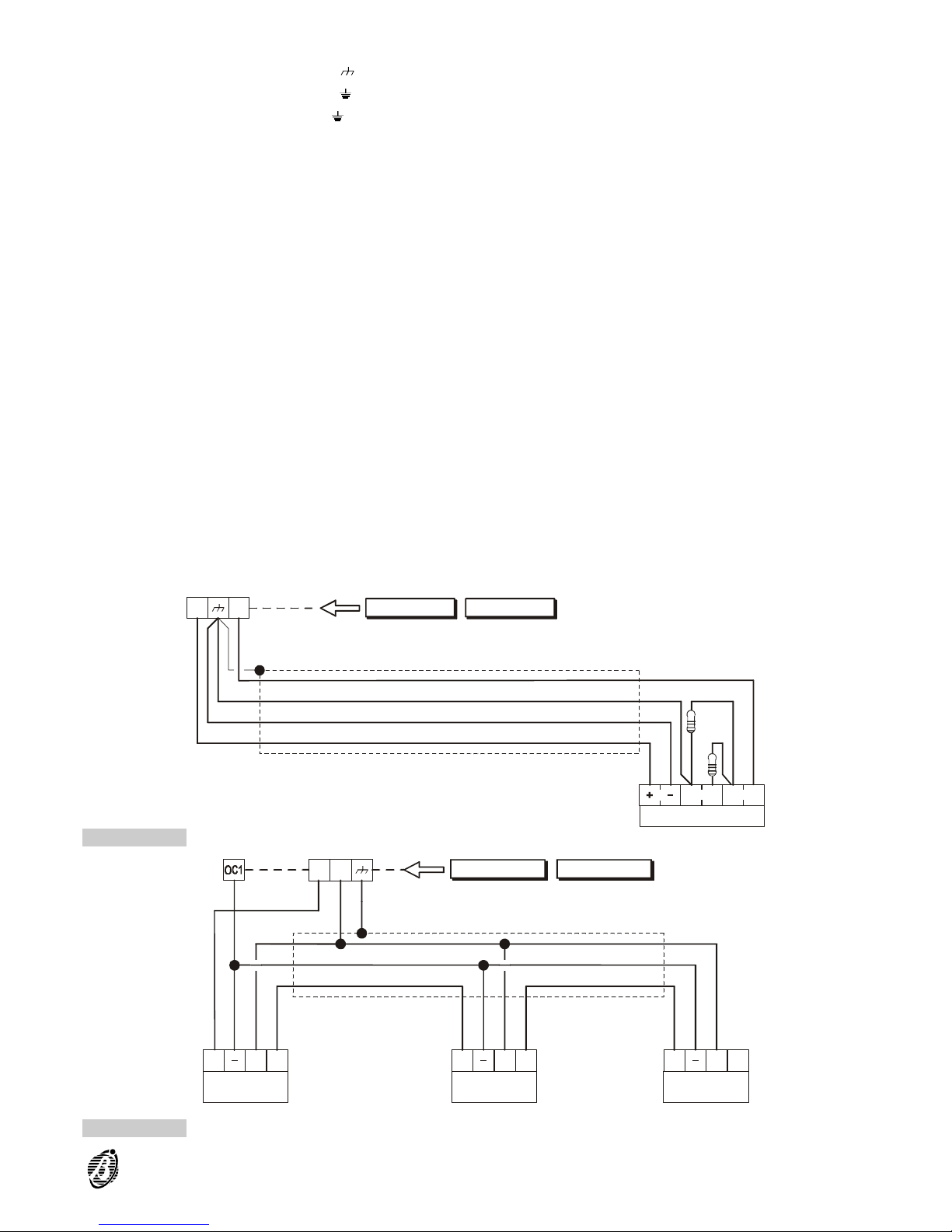
The following terminals supply the sensors:
---- [+F] (positive) and [] (negative) on Omnia and Omnia/S
---- [+F] (positive) and [] (negative) on Input Expanders
---- [+] (positive) and [] (negative) on Keypads
Each zone supports several sensors, however, if only one is connected per zone, it will be possible to identify the
zones in the event of alarms.
It is possible to connect sensors with normally closed contacts and normally open contacts. All input zones are
programmable as Normally Closed, Normally Open, Balanced or Double balanced.
Use the 10 K resistors (provided) for Balanced or Double Balanced Zones.
The Balance resistors are not required for Normally Closed or Normally Open zones.
10K
10K
sensor
N. C. A.
L1+F
S.
Main unit Input exp.
Figure 16 Connecting a Sensor to a Double Balanced line
fire
detector
fire
detector
fire
detector
+A +A+AR RR+B
+F L2
+B+B
Main unit Input exp.
Figure 17 Connecting Fire detectors (the example shows 3 Fire detectors)
INSTALLATION 25
Page 26
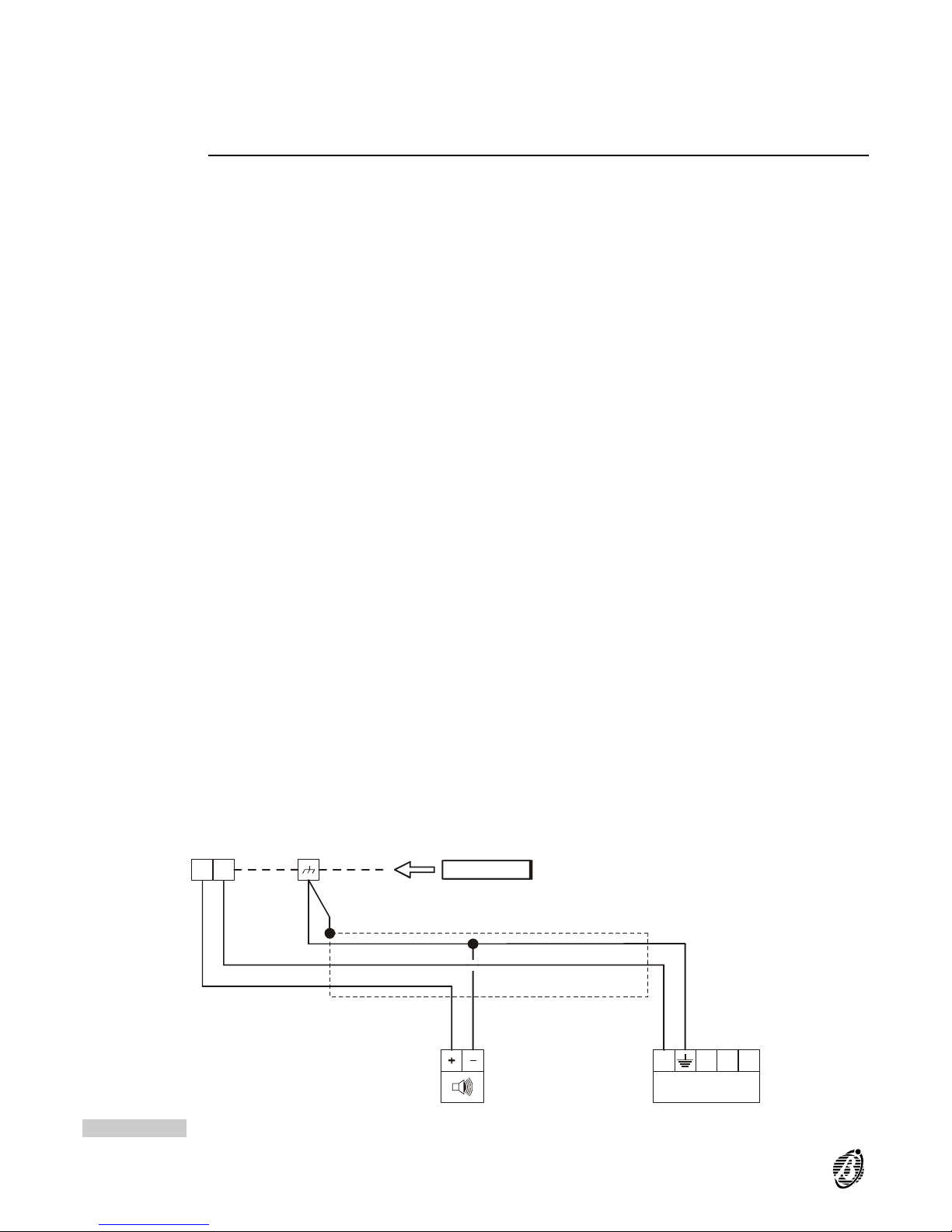
Double
balanced
The double balanced mode provides information on sensor alarm and tamper, and also identifies the sensor signalling alarm.
The schematic diagrams show the connection of sensors to Normally Closed, Balanced and Double Balanced
zones.
+
Refer to Tamper Terminal for the connection of the A.S. terminals.
Connecting Fire sensors
The Academy40 can manage fire sensors with alarm-repeat outputs that operate at 12 V (e.g. BENTEL SECURITY sensors RT101-RT102 and RF501).
+
Refer to Figure 20 for the connection schematic.
Connect the alarm-repeat outputs of the fire sensors in parallel to an input zone programmed as FIRE (Normally
Open----24h).
Connect the positive supply terminal of the fire sensors to terminals:
---- [+F] on Input Expanders
---- [+B] on Academy40 and Academy40/S
---- [+] on Keypads
Connect the negative supply terminal of the fire sensors in parallel to a Panel output or Output Expander programmed as:
---- Monostable
---- Normally Closed
---- 20 seconds
Assign the output to an event that will reset the fire sensors (e.g. Reset Panel or Reset Partition). When the programmed event occurs, the negative power supply of the fire sensors will be interrupted for 20 seconds, and reset
the fire sensors.
+A1+N1 Main unit
self-powered
siren
+N -A S1S
Figure 18 Connecting Self-powered and Indoor sirens
26 Expandable Multifunction Control Panel Omnia
Page 27
Connecting Signalling devices
Alarm signalling devices such as: Self-powered sirens, Indoor sirens and Telephone diallers are classified as follows.
Intrinsic security devices (e.g. Self-powered sirens----see Figure 18) will be activated by voltage failure on the
alarm terminal.
Positive alarm line devices (e.g. Indoor sirens----see Figure 18) will be activated by positive (12 V) on the alarm
terminal.
Negative alarm line devices are activated by negative on the alarm terminal.
Balanced alarm-line devices are activated by unbalanced impedance on the alarm terminal.
Panel terminals [+N1] and [+N2] can activate Intrinsic security devices, and Panel terminals [+A1] and [+A2]
can activate Positive alarm line devices.
Panel terminals [NA1--NC1--C1] and [NA2--NC2--C2] can activate all types of signalling devices.
The Panel and Output Expanders have Open-Collector outputs (terminals [OC1] and [OC2], etc.) that can activate
Negative alarm line devices directly, and all types of signalling devices through Omnia/4R Relay board.
IMPORTANT In order to comply with IMQ Security System Regulations----relays must be connected to the
Open-Collector outputs.
Refer to Tamper Terminals for the connection of terminals [S] and [S1].
Connecting Tamper terminals
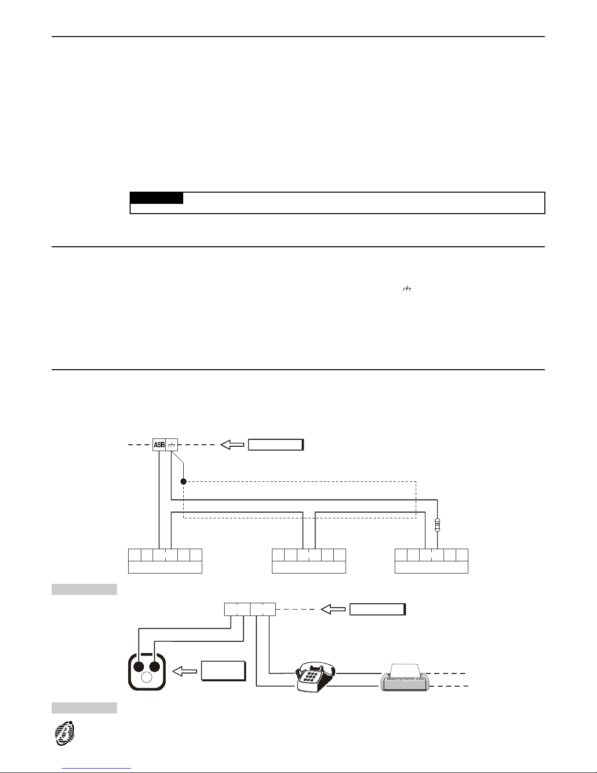
The alarm device tamper switches can be connected to the 24h balanced tamper line of the Panel, as per below
(see Figure 19).
Connect all the alarm device tamper switches in series.
Connect one end of the series to terminal [ASB] and the other to terminal [ ]; connect the balance resistor to the
last device.
+
If the tamper line is used, the device in tamper status will not be identified.
----For sensor identification----connect the sensor tamper terminal and alarm terminal to a Double Balanced zone,
as per the instructions in the Connecting Alarm Sensors section.
----For device identification----connect the device tamper terminal to a 24h zone.
Connecting the Telephone-line
Connect the telephone line to terminals [LE] to enable the telephone communicator functions.
If the telephone line is not connected to the Panel, the Disable Telephone line check option must be activated,
otherwise, the Telephone Line Trouble event will be logged repeatedly in the Event Buffer (refer to Options in
the PROGRAMMING section).
If the Panel shares the telephone line with another telephone device----connect the latter to terminals [LI]. In this
way, the Panel will take priority only in the event of an alarm.
A. A.A.S. S.S.
Main unit
10K
Figure 19 Connecting Tamper terminals
Telephone
plug
a
c
LE LI
Main unit
b
Figure 20 Connecting the Telephone line
INSTALLATION 27
Page 28
+
Connect the earth terminal [ ] to the Mains earth line----in order to protect the PCB against surges from the telephone line.
IMPORTANT Ensure that the Mains earth line is fully intact and operating properly before connecting the tele-
phone line.
Connecting the Power supply
IMPORTANT Safety regulations state that the Mains must be equipped with a bipolar isolating device for protec-
tion against over voltage and short-circuit to earth (e.g. automatic isolating switch).
Omnia is powered by a mains voltage of 230V/50 Hz through an on-board linear power supply.
Omnia/S is powered by a mains voltage of 230V/50 Hz through a switching power supply inside the cabinet.
+
The backup battery will supply power in the event of Mains Failure.
Mains failure will be signalled by:
LED on the Panel OFF
LED on the keypads ON
Warning mains failure event (this event can be delayed).
Low battery will be signalled by the Low battery event----Troubles must be cleared before the battery empties.
However, in the event of total blackout (Mains and battery) the non-volatile memory will store all the programmed
parameters.
Connecting the
Mains
Step 1 Using the plugs 27, connect the battery----Red wire to Positive terminal----Black wire to Negative terminal (see
Figure 3 Parts Identification).
Step 2
Connect the Earth wire to terminal [ ], the Neutral wire to terminal [N], and the Line wire to terminal [L] on the
terminal board 25.
+
The Fuse 29 (F 8A 250 V) will protect the backup battery against polarity inversion.
Once the Mains connection has been completed the Panel will perform an Auto-configuration phase (see below), when this phase ends the LEDs on the Panel will be as follows:
Green LED ON
Red LED OFF
Red LED OFF
Auto
configuration
The Auto-configuration phase takes approximately 15 seconds and will signalled by blinking on the red LED. During this phase the Panel will learn the configuration of the BPI Bus peripherals----the memorized configuration can
be changed during the programming phase.
When this phase ends, the keypad displays will show .
Connect the jumper 7 (MEM) to enable the non-volatile memory----a ll programmed data will be saved in the event
of blackout.
IMPORTANT The memory battery will be empty on Startup. Therefore, it must be charged for approximately 1
hour, in order to ensure one month’s storage of the programmed data during total blackout (Mains and backup
battery). The jumper 7 (MEM) must be connected.
ØØ:Ø1 Ø5/Ø3/1996ØØ:Ø1 Ø5/Ø3/1996
DDDDDDDDDDDDDDDD
28 Expandable Multifunction Control Panel Omnia
Page 29

PROGRAMMING
This Panel can be programmed via computer or keypad. The Omnia application----f rom the optional Security Suite
so ftw are----p rov ides a trouble-free way of programming the Panel. This section holds in-detail information on the
system parameters, and should be referred to when programming via keypad.
+
Refer to the Security Suite manual for further information on the Omnia application.
Programming via
computer
Step 1 Install Security Suite as per the instructions in the Security Suite manual.
Step 2 Start the Omnia application.
Step 3 Select the Panel Type (refer to Customer data section) and Firmware release (refer to Options section in the Se-
curity Suite manual).
Step 4 Program the parameters (refer to the relevant section).
Step 5 Program as per On-site Programming via computer or Remote Programming via computer (refer to the rele-
vant section).
The programmed parameters can be saved on the computer hard disk, or on a floppy disk, and downloaded onsite or via telephone line to the Panel (refer to the Save and Open Customer sections in the Security Suite manual).
The parameters of each feature are grouped together in pages. The pages in this section follow the page order in
the application.
PROGRAMMING 29
Page 30
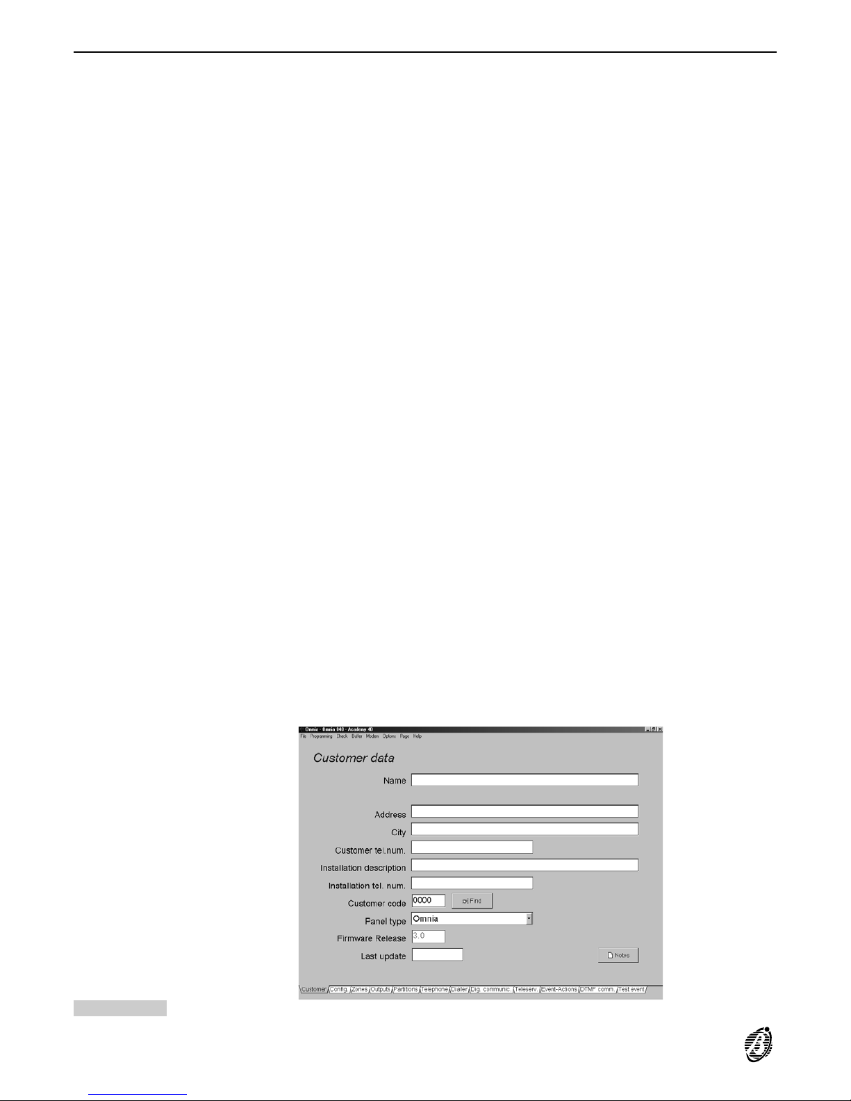
Customer data
The program opens on the Customer data window.
The top row shows the File; Programming; Check; Buffer; Modem; Options; Page and Help menus.
The tags on the bottom row open the Customer; Zones; Outputs; Partitions; Telephone; Dialler; Digital
comm.; Teleserv.; Events-Actions; DTMF comm. and Test event pages----click the tag to open the corresponding page.
The Customer’s Address, City, Customer tel.num and Installation description are for Customer identification
purposes only.
The Essential data: Name; Installation tel. num. and Customer code must be programmed as per below.
Name Enter the Customer name.
Installation tel.
num.
Enter the number of the telephone the Panel is connected to. The B-MOD modem will call this number when the
Connecting option is enabled (from the Modem menu). This number need not necessarily be the same as the
Customer tel.num (e.g. If the Customer has several telephone lines).
Accepted digits: 0 through 9 and commas (,). The comma represents pauses of 2 seconds (e.g. between the prefix
and the telephone number).
Customer code Enter the Customer code in this space. This code will identify the Panel during communications with the B-MOD
modem (for Teleservice or Test calls). Therefore, each Panel must have a different Customer code. Duplicate
codes will be signalled when Save is selected (the code and the Panel it is assigned to will be shown).
+
The Customer code----entered on the Customer data page----will be copied automatically onto the Teleservice
page, and vice versa.
Panel type Select Omnia for Omnia and Omnia/S.
Firmware Release This is a non-modifiable field that will show the selected firmware release (selected from the Options menu or
downloaded from the Panel). The program will supply the relevant parameters.
Select File then click Save to save the Customer data.
Last update This parameter will be updated automatically when Save is selected.
Notes Data entered on the notepad will not be shown in the Installation description. If the notepad is empty the icon will
show an empty page.
Figure 21 Customer data page
30 Expandable Multifunction Control Panel Omnia
Page 31
Configuration
On initial Startup the Panel will perform an auto-configuration cycle.
+
The configuration learned during this cycle will become the recognized BPI Bus configuration (refer to the Connecting the Power supply section). Any changes must be made by the Installer.
Proper functioning of the Panel depends on the BPI Bus configuration. The Panel will match each configuration
reading with the programmed configuration. Mismatch----due to the loss of a peripheral----will generate a BPI Fault
Alarm.
Select the Upload > Page option from the Programming menu to view the configuration.
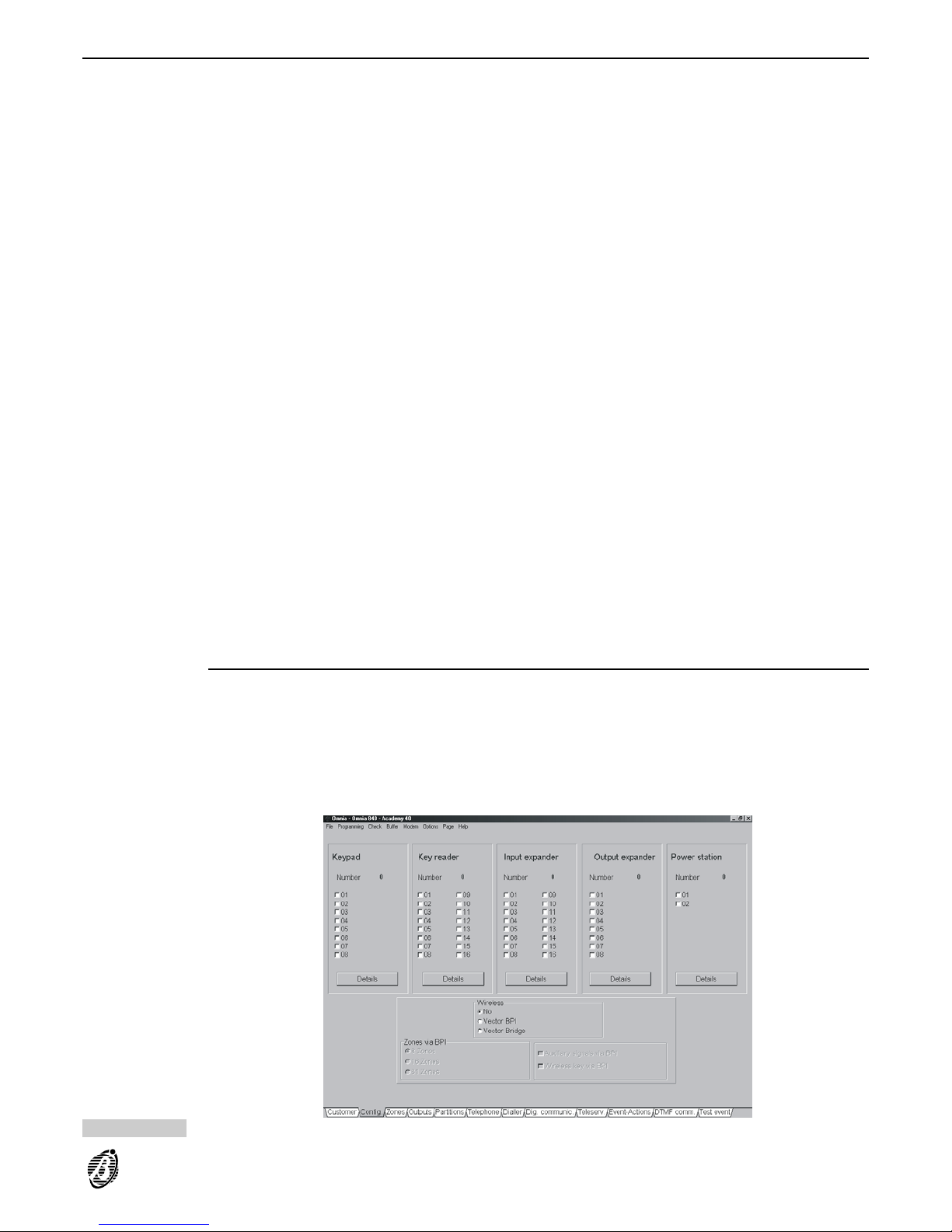
Click the Config. tag to open the configuration page.
The Config. (Configuration) page is divided into sections----o ne f or e ach d evice type (Keypad, Reader, Input expander, Output expander, Power station).
Each section has a column of numbered check boxes----the number corresponds to the peripheral address (refer
to Connecting BPI Peripherals section for details).
Configuration setup:
box checked = peripheral in configuration
box clear = peripheral not in configuration
Only the peripherals in the configuration can be controlled by the Panel.
Configuration Done:
Click Details to open the Details window.
Details windows
no. The non-modifiable no. column will show the peripheral address. The address depends on the configuration of the
device DIP switches.
Description The modifiable Description column will show Keypad 001, Keypad 002, and so forth (at default).
Enter the device placement e.g. Garage, Cloakroom, etc. (maximum 16 characters). This will be the placement
identifier.
Program the parameters of the device type. Keypad and Reader parameters must also be programmed, as per the
instructions in the relevant sections.
Select OK to save data and exit the window.
Select Cancel to exit the window without saving.
Select Help for further information.
Select Print (if available) to print the open page.
Keypads
1 ... 8 Numbers 1 through 8 (top left of window) correspond to the partitions. Assign the keypad to the partitions it will
control (arm, disarm, etc.).
Yes = keypad enabled on the corresponding partition
No = keypad disabled on the corresponding partition
Double click to toggle the status.
+
Keypads need not necessarily be assigned to partitions, and can be used for programming, display and other operating purposes.
Figure 22 Configuration page
PROGRAMMING 31
Page 32

Readers
The Panel supports up to 16 Readers and up to 250 Keys/Cards. The following parameters apply to Readers
only. Keys/Cards must be programmed via keypad, as per the instructions in the Keys/Cards section.
+
Enabled Keys/Cards can perform the following operations:
Partition arming
Partition disarming
Type A or B arming mode
Stop Alarm on partitions
RED spot
(corresponds to
the Red LED on
the Reader)
Numbers 1 through 8 on the top row correspond to the partitions.
Assign the Reader to the partitions it will control (arm, disarm, stop alarm signalling, etc.).
Double click (or press ENTER) on the selected box to toggle the status.
Yes = Reader enabled on the corresponding partition.
All the enabled partitions will arm----if the Key/Card is removed from the Reader when the RED LED is ON.
AMBER spot
(corresponds to
the Amber LED
on the Reader)
Select the partitions for Type A arming.
Double click (or press ENTER) on the selected box to toggle the status.
Partitions with A will arm, and those with D will disarm----if the Key/Card is removed from the Reader when the
AMBER LED is ON.
GREEN spot
(corresponds to
the Green LED on
the Reader)
Select the partitions for Type B arming.
Double click (or press ENTER) on the selected box to toggle the status.
Partitions with A will arm, and those with D will disarm----if t he Key/Card is removed from the Reader when the
GREEN LED is ON.
Wireless
The Wireless section of the Configuration page is for hybrid systems, that is, systems that manage hardwired
and wireless devices via VectorBRIDGE or VectorBPI. Refer to the relevant Manual for the wireless device programming procedure.
Zones
The zones (terminals [L1], [L2], etc.) can be programmed as Alarm or Command zones.
Alarm zones Violation of an Alarm zone----dur ing a rmed status of its partition (refer to Partitions) will generate an Alarm on
zone event. One or more actions can be assigned to this event (activation of sirens, digital communicator, tele-
phone dialler etc.).
The Panel will start monitoring zones----other than Exit delay or Last exit zones (refer to Type)----as soon as their
partitions arm.
The Panel will start monitoring Exit delay and Last exit zones when the programmed Exit time of the partition
elapses (refer to Partitions).
Alarm status will be generated when the zone is unbalanced (refer to Balancing) for the programmed cycle and
time (refer to Sensitivity).
Each zone can generate the Alarm on zone event for the programmed cycle only (refer to Cycles).
Command zones Violation of a Command zone will activate one of the following:
Switch status of partitions
Arm partitions only
Disarm partitions only
Reset partition
Reset Panel
Clear call queue
Unbalancing will activate the Command zone (refer to Balancing) for its programmed cycle and time (refer to
Sensitivity).
Zone Table
The non-modifiable Zone table, on the left side of the page, shows the available zones (refer to Config. page).
no. Shows the zone identifier number that sometimes substitutes the full description (refer to Description).
Position Shows the label (Description) of the hardware component the zone is assigned to. This description can be
changed in the Config.
page and can be used as the device placement identifier.
Device Shows the address of the device the zone is assigned to (addresses 1 through 8 for keypad zones; and addresses
1 through 16 for Input-Expander zones).
Ter. Shows the zone terminal acronym.
32 Expandable Multifunction Control Panel Omnia
Page 33
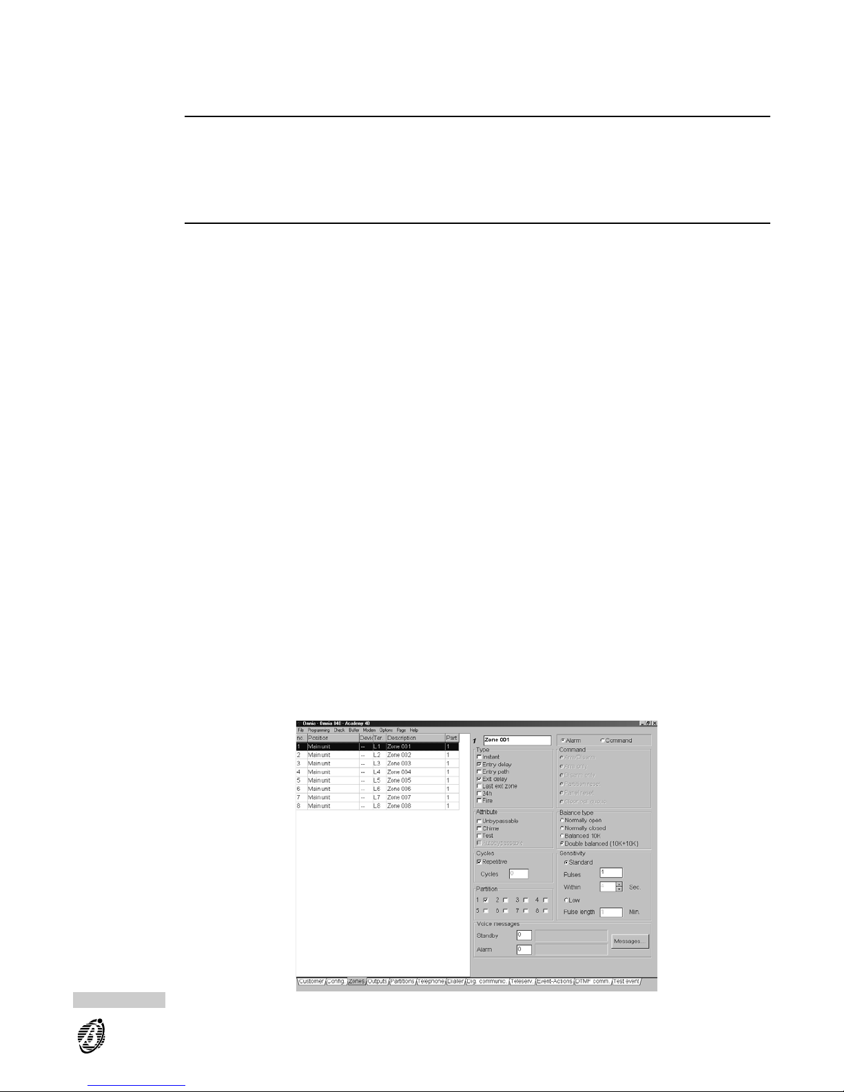
Description Shows the zone label (maximum 16 characters)----used as the zone identifier in all parts of the program, and also
in the event buffer.
Partition Shows the partition the zone is assigned to----Command zones will be indicated by an asterisk.
Zone programming
To program zone parameters:
Select the required zone from the Zone table----the zone number will appear in a box on the top right of the page.
Enter the zone label (Description).
The label will be transferred automatically to the corresponding box in the zone table.
+
Step from zone to zone without saving----the data will be saved automatically on the hard disk.
Type
This parameter determines the actions the zone will generate when violated during armed/disarmed status, and
also whether zone violation will generate Fire, 24h or Burglar type alarm events, at partition and Panel level.
+
All Zones----other than Fire or 24h----will be classified as Burglar.
Select the Type.
Instant Violation of an Instant zone will generate:
Alarm on zone no.
Burglar alarm on partition no., Generic alarm on partition no. and Generic+Tamper alarm on partition no.
on the partition of the zone
Burglar alarm on panel, Generic alarm on panel and Generic+Tamper alarm on panel
Entry delay Violation of an Entry delay zone----during the programmed Entry Time of its partition----will not generate events.
However, if the partition is not disarmed before the delay elapses, or if the zone is violated after the delay, the
events assigned to Instant zones will be generated.
The first zone on the path to the partition disarm-point should be programmed as an Entry delay zone.
Entry path Violation of an Entry path zone----after violation of an Entry delay z one----will generate the events assigned to In-
stant zones, when the programmed delay elapses.
The events assigned to Instant zones will be generated, if the Entry Time is not running or has elapsed.
+
Zones on the way to the partition disarm-point should be Entry path zones.
Exit delay Violation of an Exit delay zo ne----during the programmed Exit Time of its partition----will not generate any events.
In all other cases, the events assigned to Instant zones will be generated.
+
Zones on the way out of a partition should be Exit delay zones.
Last exit Violation of a Last exit zone----during the programmed Exit time of its partition----will not generate any events.
However, the Last exit zone will temporarily assume the new value (the time actually taken to leave the protected
partition), and therefore, monitoring will start immediately. In all other cases, the events assigned to Instant zones
will be generated.
+
The last zone on the way out of a partition should be programmed as the Last exit zone.
Figure 23 Zones page
PROGRAMMING 33
Page 34
24h Violation of a 24h zone----regardless of the status of its partition (armed/disarmed) will generate:
Alarm on zone no.
24h alarm on partition no., Generic alarm on partition no. and Generic+Tamper alarm on partition no.
24h alarm on panel, Generic alarm on panel and Generic+Tamper alarm on panel
Fire Violation of a Fire z one----r egardless of the status of its partition (armed/disarmed) will generate:
Alarm on zone no.
Fire alarm on partition no., Generic alarm on partition no. and Generic+Tamper alarm on partition no. on
the partition of the zone
Fire alarm on panel, Generic alarm on panel and Generic+Tamper alarm on panel
Attributes
The following parameters are for Alarm zones only.
Assign Attributes.
Unbypassable Zones with this attribute cannot be bypassed.
Chime Violation of a Chime zone----during disarmed status of its partition----will generate the Chime on partition no.
event (signalled by slow beeping on the enabled keypads of the partition).
Violation of a Chime zone----during armed status of its partition----will generate the actions programmed for the
Type parameter.
+
The Chime attribute will not affect the 24h or Fire zones.
Test Violation of a Test zone will not generate the Alarm on zone no. event. However, the <<Alarm on zones being
tested>> message will be logged in the Panel event buffer.
By default only events that occur when the partition is armed will be logged. To log events that occur during armed
and disarmed status, enable the Maintain Zone Test Attribute (Options----Programming menu).
+
If any unbypassed zones have the Test attribute, the indicator on the keypad will blink.
Auto-bypassable A zone with this attribute will be bypassed automatically----i f violated during armed status of its partition. The zone
will be unbypassed automatically when its partition is next disarmed
+
The Auto-bypassable attribute will not affect Exit delay zones.
The Exit delay of the partition of an Auto-bypassable zone must be over 5 seconds.
Balance Type
A zone will signal violation when the electrical conditions of its Balance Type are present on the corresponding input terminal for at least 0.3 seconds.
Select the Balance Type.
Normally open The zone must be open (floating) during standby status. An alarm will be generated when the zone switches to
ground (e.g. for fire detector connections).
IMPORTANT If zones are programmed as Normally open, the IMQ/A Certification will no longer be applicable,
as the zones will not be protected against wire cutting.
Normally closed The zone terminal must be connected to ground during standby status. An alarm will be generated when the zone
opens (floating).
IMPORTANT If zones are programmed as Normally closed, the Performance Class of the Omnia and Omnia/S
Panels will be downgraded from Grade
IIII to grade, as the zones will not be protected against short-circuits.
Balanced 10K The zone must be connected to ground by a 10K (10,000 ohm) resistor during standby status. If short-circuited to
ground----the Panel will detect tamper and will generate:
Tamper on zone no.
Tamper alarm on partition no. and Generic+Tamper alarm on partition no. on the partition of the zone
Tamper alarm on panel and Generic+Tamper alarm on panel
In all other cases (unbalanced, open zones etc.) the Panel will detect violation (refer to Type).
Double balanced The zone must be connected to ground by two 10 K (10,000 ohm) resistors. The Panel will generate the events
specified for the zone type (refer to the Type), if one of the resistors disconnects.
In all other cases, the Panel will detect tamper and generate the events programmed for tamper on balanced 10K
zones.
This Balance Type (only 2 wires) allows detection of the open alarm/tamper contacts of the connected sensors (refer to Connecting Alarm sensors).
+
Command Lines should not be programmed as Double Balanced, as recognition of a Tamper on zone no. event
cannot generate actions.
34 Expandable Multifunction Control Panel Omnia
Page 35

Cycles
This parameter determines the number of times the zone will signal an alarm status before being bypassed on the
analysis, as per the following values.
Enter the required number of cycles under Cycles.
0 Violation on the zone will be ignored.
1 ÷254
The zone will signal alarm status, as per programming, the zone will then be bypassed on the analysis until one of
the following conditions occurs:
Status change on its partition
Reset on its partition
Exit Stop-Alarm status on its partition (via keypad by User code or via reader by key)
Exit programming session (via keypad or by local or remote connection)
+
All the previously mentioned conditions clear the alarm-cycle counter.
Repetitive If a zone is programmed as Repetitive the cycles will be unlimited.
+
A zone in persistent alarm status (e.g. due to faults) will activate one alarm cycle only. This function mode is explicitly required by CEI 79/2 regulations. The zone will be unable to generate another cycle until the alarm counter
is cleared, or the zone is unbypassed.
Partition
Alarm Zone Command Zone
This shows the partition the zone is assigned to, and
therefore, the enabled User codes, Keys and also programmed times. Each Alarm zone should be assigned to
one partition only. It is not necessary to assign a zone to
several partitions, as the Panel manages partition dependency (refer to Partitions).
This shows the partitions the Command zone is
assigned to. Each Command zone can operate more
than one partition.
It is not possible to specify the partitions for the Panel
Reset and Clear Calls options, as in this case the
partitions are irrelevant.
Sensitivity
Standard If this option is selected the zone will generate an alarm when the programmed number of Pulses are detected
Within the programmed number of seconds, as follows.
Pulses: enter the number of pulses (1 through 3).
Within: enter the seconds (4 through 32).
Low If this option is selected the zone will generate an alarm when it is unbalanced (violated) for more than the pro-
grammed Pulse length time, as follows.
Pulse length: enter the number of minutes (1 through 16).
Voice messages
It is possible to assign 2 of the 14 Voice messages to the zone----for Status Enquiry via telephone (to check on
connected appliances, such as: heating system, garden sprinkler, courtesy lights, etc.
Enter the assigned message number:
Standby The assigned message will play when the zone is in Standby status.
+
If no Voice message is specified----Standby status will be signalled by a beep.
Alarm The message assigned in this field will play when the zone is in Alarm status.
+
If no Voice message is specified----Alarm status will be signalled by two beeps.
Messages... Click Messages (bottom left of page) to open the message description window then enter the message labels
(maximum 16 characters per message). Select Download to download the Messages to the Panel.
+
The voice messages must be recorded, played and deleted via keypad. These options are provided by the optional OmniaVox kit (Voice board + Microphone board + Speaker).
PROGRAMMING 35
Page 36
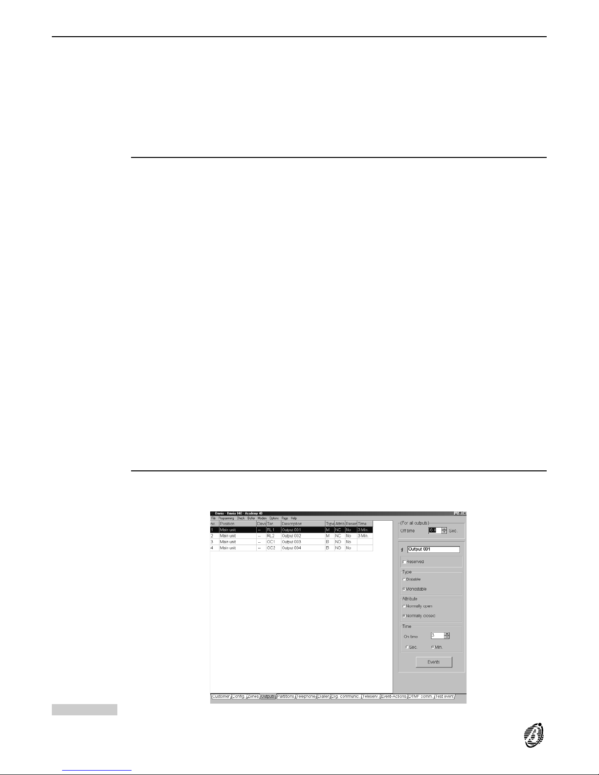
Outputs
The Main units of Omnia and Omnia/S have:
----two 1A open-collector outputs (Terminals [OC1] and [OC2])
----two 3 A re lays (Terminals [NA1], [NC1], [C1], [+A1], [+N1]) and [NA2], [NC2], [C2], [+A2], [+N2])
The Omnia/OUT expanders have four 0.15 A open-collector outputs (Terminals [OC1], [OC2], [OC3] and [OC4]).
The buzzer on board the Omnia/OUT expander can be connected to terminal [OC4] with positive or negative
logic----depending on the jumper 68.
All outputs are programmable, and can be associated with the events that activate signalling devices (sirens and
flashers, etc.). Outputs can also be used for fault status signalling and device control, and can be programmed for
remote control of connected appliances (heating, garden sprinklers, etc.).
Outputs page
All the outputs can be programmed in this page.
Select the required output from the Outputs table (left side of the page) and program in the programming section
(right side of the page).
Page description:
no. This is the output identifier number used in the Event-Actions page (when assigning the corresponding output to
the required events).
Position This is the Description of the output hardware device. The Description can be changed in the Config. page.
Device This is the Output expander address.
This parameter does not apply to Main unit Outputs.
Ter. This is the output terminal identifier:
----RL1 corresponds to terminals [NA1] - [NC1] - [C1] - [+A1] - [+N1]
----RL2 corresponds to terminals [NA2] - [NC2] - [C2] - [+A2] - [+N2]
Description This is output Description.
Type This is the type ---- Bistable (B) or Monostable (M).
Attrib. This is the attribute ---- Normally closed (NC) or Normally open (NO).
Reserv. This indicates whether or not the output is Reserved for manual control. Manual arming must be done via keypad
(USER MENU, Outs control) or via telephone.
Time Monostable outputs----this is the output activation time.
Bistable outputs----this field will be empty.
All the programmable output parameters, selected from the Output table, can be changed on the right side of the
Output page, as follows.
Description
This is the output label (maximum 16 characters) that will be used in all parts of the program as the output identifier----the label will be copied onto the left side of the Outputs page. The output identifier number (1 through 36) of
will be shown to the left of the Description.
Figure 24 Outputs page
36 Expandable Multifunction Control Panel Omnia
Page 37

Reserved Outputs (manual)
The outputs can be used to switch ON/OFF electrical appliances, from a remote keypad or via telephone.
Reserved outputs cannot be assigned to events, and therefore, their status will be determined by the commands
given via keypad or telephone.
Reserved outputs should not be programmed as Monostable----a s they must be activated/stopped manually.
(Refer to the Output activation section and the TELEPHONE OPERATIONS section in the USER MANUAL).
Type
Bistable Bistable outputs will be activated when at least one of their assigned events occurs, and will reset when all the as-
signed events end.
Monostable Monostable outputs will be activated when one of their assigned event occurs. Activated status will be held for the
programmed On time, after which, Standby status will be restored for the programmed Off Time.
Attribute
The Normally open or Normally closed attribute will determine the electrical conditions of the output during
standby status, as follows.
Normally open The Open-collector outputs (terminals [OCx]) will be open; the Intrinsic security outputs (terminals [+Nx]) will be
open; positive (13.8 V) will be present on the positive outputs (terminals [+Ax]; the Common terminals of the freevoltage changeover contacts of the output relays (terminals [Cx]) will be connected to the corresponding Normally
open contacts (terminals [NAx]).
Normally closed Ground will be present on the Open-collector outputs (terminals [OCx]); positive (13.8 V) will be present on the in-
trinsic security outputs (terminals [+Nx]); the positive outputs (terminals [+Ax]) will be open; the Common terminals
of the free-voltage changeover contacts of the output relays (terminals [Cx]) will be connected to the corresponding Normally Closed contacts (terminals [NCx]).
Times
On time This is the maximum activation time of the output.
+
The On time applies to the Monostable outputs only, as the Bistable output will reset when all the assigned
events end.
Each Monostable output may have a different On time:
from 0.0 through 25.4 seconds----in steps of 0.2 seconds (Sec. option);
from 1 through 128 minutes in steps of 1 minute (Min. option).
By default the Monostable output On time is 3 minutes.
Off Time
An output cannot be re-activated until the Off Time elapses.
+
The selected Off Time will apply to all Monostable outputs. The Off Time does not apply to Bistable outputs.
Off Time: 0.0 through 127.5 seconds in steps of 0.5 second (default = 6.0 seconds).
PROGRAMMING 37
Page 38
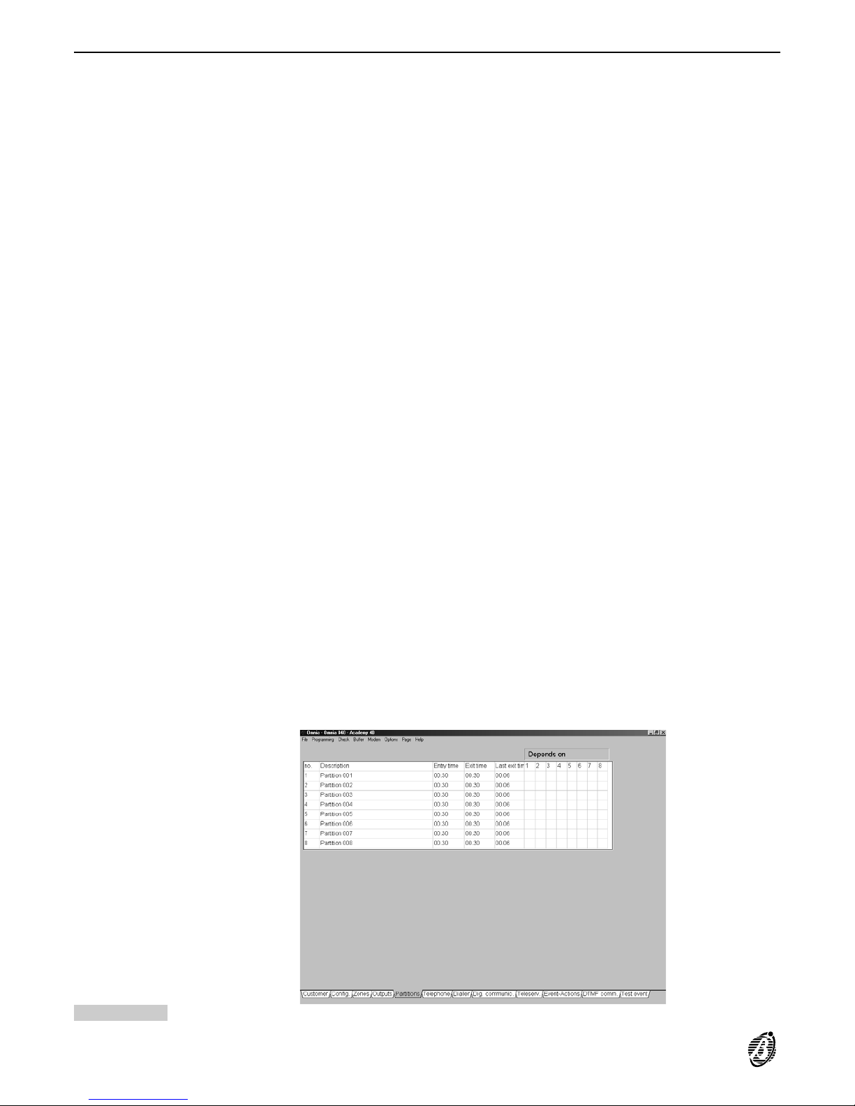
Partitions
A partition is a group of zones. The Panel can manage up to 8 partitions (to be defined in the Zones page). Each
partition can be programmed with its own Codes, Times, Output actions etc., and can interact with the other partitions.
+
A partition can comprise several input zones, however, a zone can be assigned to one partition only.
The partition parameters must be defined on the Partition programming page, as follows.
no. The non-modifiable partition identifier number will be used instead of the partition label (e.g. status enquiry via tele-
phone).
Description Assign a label to the partition (maximum 16 characters). This label will be used as the partition identifier in all parts
of the program, and in the event buffer.
Entry time Program the Entry time. Violation of an armed Entry delay zone will activate the programmed delay. The Entry
time will be signalled by:
activation of the Entry time on partition no. event;
an audible signal on all the enabled keypads of the violated partition.
An alarm will not be generated if the partition is disarmed before the delay elapses.
Exit time Program the Exit time. Violation of an armed Exit delay zone will generate the programmed delay. Violation of the
zone during the programmed delay will not generate an alarm.
The Exit time will be signalled by:
activation of the Exit time on partition no. event;
an audible signal on all the enabled keypads of the armed partition.
Last exit time Violation of a Last exit zone----during the programmed Exit time of its partition----will not generate any events.
However, the Last exit zone will temporarily assume the new value (i.e. the time actually taken to exit the protected partition).
Depends on The partition will be subordinate to the selected partitions.
Double click (Yes /No) or press ENTER on the selected box to toggle the status.
Dependent partitions will arm automatically when all the partitions they depend on arm;
Dependent partitions will disarm automatically when one of the partitions they depend on disarms.
+
The Dependent partition can be armed/disarmed manually by enabled User Codes/Keys/Cards.
+
A partition should not be programmed as depending on itself.
Figure 25 Partitions page
38 Expandable Multifunction Control Panel Omnia
Page 39
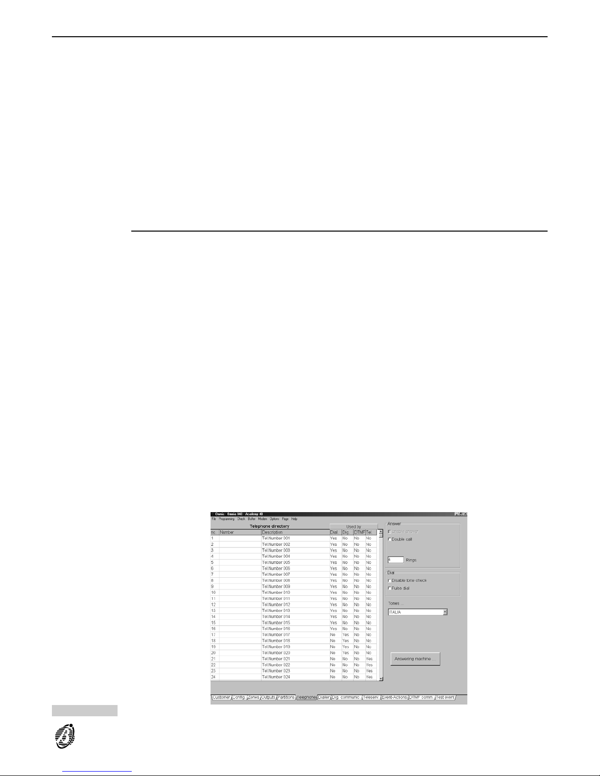
Telephone
This page holds up to 32 telephone numbers (Phonebook), and the telephone line data.
The parameters must be programmed as follows.
no. The non-modifiable identifier number (1 through 32) will be used instead of the entire telephone number.
Number Enter the entire telephone number----maximum 16 digits including pauses. Accepted digits: 0 through 9 and the
comma (,). Use the comma for pauses (between the prefix and telephone number). The telephone number will be
used by the:
----Telephone Dialler
----Digital Communicator
----DTM F com municator, and for Teleservice requests.
Description Enter the name of the telephone number user (maximum 16 characters).
Used by The Used by table has 4 columns: Dial.; Pulse; DTMF; Tel. The table will show whether a telephone number was
used by the Telephone Dialler (Dial.), by the Digital Communicator (Pulse), by the DTMF communicator (DTMF)
or Teleservice ( Tel.).
Answer
The Panel will answer incoming calls in accordance with the following parameters.
To enable the Panel to answer calls:
----sel ect the En./Dis. Answer. or En./Dis. Teleser. option from the USER MENU. The answer message must be
recorded beforehand (refer to Answering machine).
The Panel will answer after the programmed number of Rings, unless the Double call option is enabled.
Enable answer Omnia 2.0 and successive releases do not have this option, as the enable/disable answer option is for the User only.
Double Call The Double Call option allows the Panel to share the telephone line with another answering device (answerphone,
fax, etc.). In normal circumstances the device with the least number of rings will answer, however, if this option is
enabled (ON), the Panel will override the other answering device when it recognizes the double call sequence.
Double call sequence: the User must call the Panel and allow 2 rings then hang up and callback within 60 seconds. The Panel will answer on the first ring of the second call.
+
The other answering device must be programmed to answer after 3 or more rings.
+
The Double call is managed by the B-MOD modem.
Rings Specify the number of rings required.
If the Double call option is enabled, this parameter will be ignored.
Figure 26 Telephone page
PROGRAMMING 39
Page 40

Dialling mode
Disable tone
check
The Panel will check for the dialling tone before dialling a telephone number. If it is not detected, the Panel will
hang-up and retry.
If the Disable tone check option is selected, the Panel will dial the telephone numbers without checking for the dialling tone. This option is useful when the Panel is connected downstream to a switchboard with non-standard
tones.
Pulse dialling The Panel operates in DTMF as is faster than Pulse dialling.
+
The Pulse dial option must be enabled, If DTMF is not available.
PSTN line parameters
Select the country----to allow the Panel to operate properly with local PSTN line parameters.
If the country is not listed----select EUROPEAN GENERIC.
If the country is not listed and local telephone line parameters are different from EUROPEAN GENERIC----Select
Disable tone Check.
Answering machine
The Answering machine option allows the Panel to answer incoming calls with a Voice message (to be recorded
by the installer).
The Answering machine option from the USER MENU must be enabled by the User (refer to Answering machine
Enable/Disable section in the USER MANUAL).
+
If the Answering machine and Teleservice options are enabled, the Panel will verify the origin of incoming calls
(this operation takes approximately 4 seconds) before playing the answer-message.The Panel will not play the
answer-message for calls from the B-Mod modem.
An audible signal will indicate that the Panel has engaged the line. A high-pitched tone (2400 Hz) will be emitted
when the Teleservice option is enabled, and a low-pitched tone (1250 Hz) when only the Answering machine option is enabled.
The answer-message allows authorized Users (refer to User codes) to call the Panel for remote enquiry on the
status of the Panel and peripherals (refer to the TELEPHONE OPERATIONS section in the USER MANUAL).
Click Answering machine, then program the following parameters.
Answer message Select the required Answer Message from the list. These messages can be programmed on the Message page
(from the Zones or Dialler page).
+
If no Answer Message is selected----t he Answering machine option cannot be enabled.
Message
repetition time
Enter how long (in seconds) the Answer-message must play.
Replay Pause Enter the interval (in seconds) between each replay.
PIN entry timeout Enter how long (in seconds) the Panel must wait for a valid code entry on the telephone keypad. If a valid code is
not entered within the specified time Panel will end the call.
+
User codes: 25 through 31 (refer to the Codes page) can be used via telephone.
DTMF tone
timeout
Enter how long (in seconds) the Panel must wait, after code acceptance, for the communication to start. If no telephone button is pressed within the specified time Panel will end the call.
40 Expandable Multifunction Control Panel Omnia
Page 41
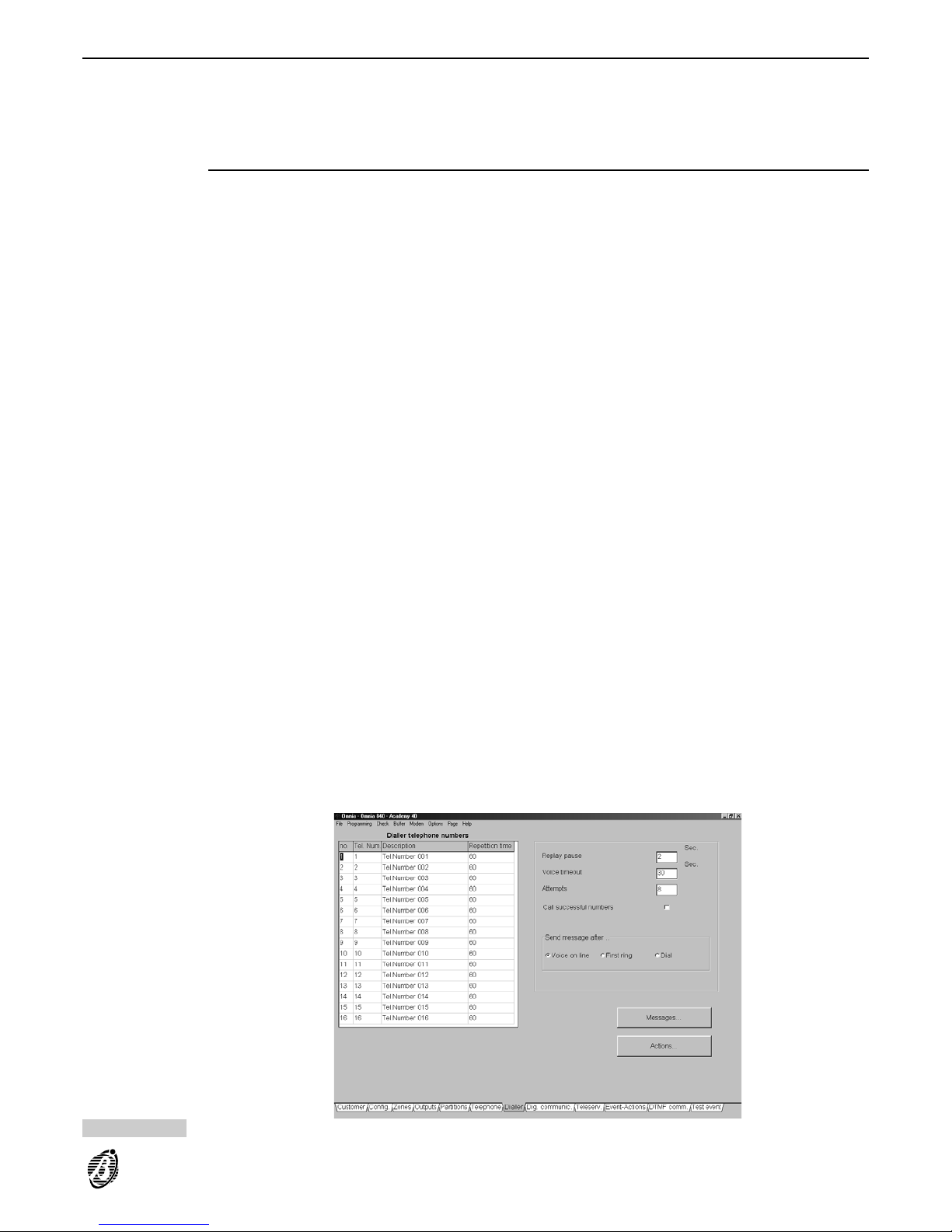
Dialler
Up to 32 Dialler actions can be programmed. The programmed actions can be assigned to the events in the
Event-Actions page. Each Dialler action will send a Voice message to signal the start/end of the corresponding
event. Refer to Dialler in the FACILITIES section for further details on Dialler programming.
Each telephone dialler action can send one of the 14 Voice Messages to up to 16 telephone numbers (selected
from the 32 programmable numbers).
Dialler Telephone Numbers
The assigned voice messages will be sent to the Dialler Telephone numbers when the programmed events occur.
The telephone number parameters can be programmed on the left side of the Dialler page, as follows.
no. This is the non-modifiable identifier number (1 through 16).
Tel. Num. Enter the identifier number (1 through 32) of the telephone number (refer to the Telephone page) that will receive
the voice message call. The telephone number label will appear automatically in the Description column.
+
It is not necessary to follow the order defined in the Telephone page, however, dialling priority will be defined by
the order established in this table.
+
The Description column can be changed in the Telephone page.
Repetition time Enter how long (in seconds) the Voice message must play. A different Repetition time can be specified for each
telephone number.
Replay pause Enter the interval (in seconds) between each voice message replay.
Voice timeout Enter how long (in seconds) the Panel must wait for a voice answer before hanging up. This parameter depends
on the Send message after option, as follows.
Voice on line: the Panel will hang up after dialling----if a voice answer is not detected within the programmed
Voice on line time.
First ring: the Panel will hang up after dialling----if a back-ring is not detected within the programmed Voice on
line time.
Dial: the Panel will send the message immediately after dialling the number.
Attempts Enter the number of tries the Panel must make in the event of a failed call.
Call successful
numbers
If this option is enabled the telephone numbers of successful calls will be redialled in the following cycles. If not,
the successful numbers will be bypassed in the successive cycles.
The programmed parameters of the Replay pause, Voice timeout, Attempts and the Call successful numbers
options will be the same for all Telephone numbers.
Figure 27 Dialler page
PROGRAMMING 41
Page 42
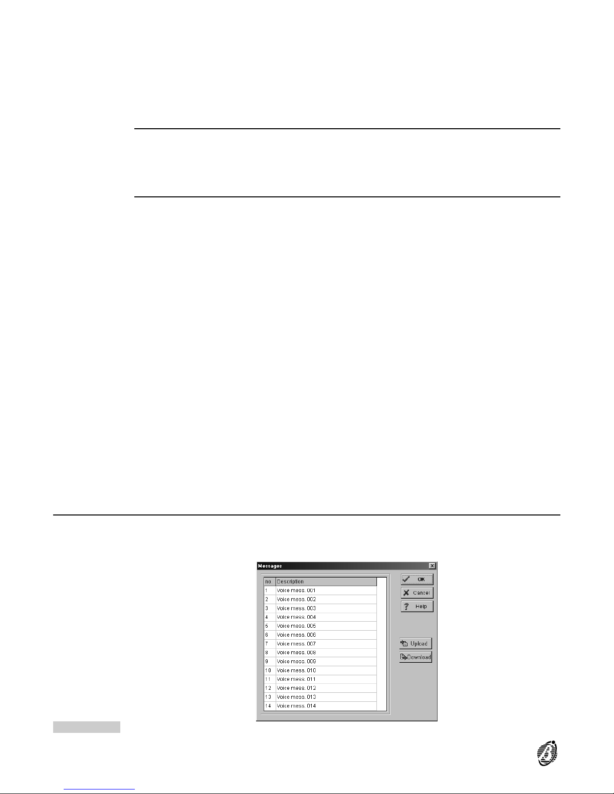
Send message
after
Specify when the voice message will be sent.
Voice on line: the message will be sent on voice answer (e.g. on "Hello").
First ring: the message will be sent after the first back-ring.
Dial: the message will be sent immediately after dialling the telephone number.
+
A Call will be considered successful when it satisfies all the conditions programmed in the Send message after
section. Only the Voice on line option ensures that calls have been answered.
Messages
Assign a label (maximum 16 characters) to the 14 Voice messages in the Messages window (see Figure 28). Select the Send button to download.
+
Voice message recording requires the OmniaVox kit (Voice board + Microphone board + Speaker). Recording,
play and deletion can be done via keypad. Refer to the OmniaVOX section for a full description of the Voice function.
Actions
Click Actions to open the Dialler actions window. Program the Dialler actions that will be assigned to specific
events in the Events/Actions Page.
Each Dialler action will send one of the 14 Voice Messages to up to 16 telephone numbers (from the 32 telephone
numbers in the Phonebook). Dialler actions will be repeated as per the programmed number of Attempts pro-
grammed in the Dialler page.
The parameters must be programmed as follows.
no. This is the identifier number of the Dialler action. Use the corresponding identifier number to assign the Dialler ac-
tion to the Event in the Events/Actions Page.
1 ... 16 The numbers on the top row of the Dialler actions window correspond to the numbers in the no. column in the
Dialler Telephone Numbers list.
Assign the Dialler Telephone Numbers to the Dialler action:
Yes = the corresponding telephone number will be dialled.
Box clear = the corresponding telephone number will not be dialled.
Double click to toggle the status.
Message Enter the identifier number of the Voice message to be sent (refer to no. column in the Messages window). The
assigned label will appear automatically in the Descr. Mess. column.
+
The Voice message label can be changed in the Messages window only.
Descr. Action Assign a label to the action----this will simplify programming in the Event-Actions page.
Events Each Action can be assigned to the several events.
To view the events that activate a specific action:
----click Events on the Dialler actions window (from the Dialler page) to view the list of events that will activate
the selected action.
----open the Events-Actions page to view the actions activated by each selected event.
Digital Communicator
Up to 256 actions can be programmed on the Digital Communicator page, Each action will communicate the
start/end of an event to the Central Station.
Figure 28 Voice message page
42 Expandable Multifunction Control Panel Omnia
Page 43
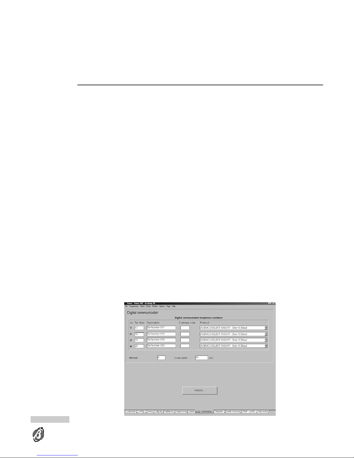
Each Digital Communicator action can send the corresponding event code (event identifier) to up to 4 telephone
numbers. Therefore, it possible to signal burglary to the Central Station, fire to the Fire Station, Fault to the Installer and send emergency requests to the Service Centre.
Each event can be assigned to 2 Digital Communicator actions (2 different codes can be assigned to each event).
This will allow the same event to be sent to two different Security Services, each with their own decoding (e.g. a
Fault event to the Installer and to the Central Station).
Event queue The communication will not end until all the events destined for the service on line have been transmitted. The
Event queue will reduce call costs and communication time.
+
Protocols with Voice management do not queue Events but transmit one event per call.
Digital Communicator telephone numbers
The Digital Communicator can manage 4 telephone numbers.
no. This is the non-modifiable identifier number (1 through 4).
Tel. Num Enter the identifier number (1 through 32) of the required telephone number (refer to the no. column in the Phone-
book----Telephone page).
Customer code Enter the 3-4 digit Customer code (accepted digits 0 through 9 and upper-case letters from B to F). This code is
usually assigned by the Central Station and functions as the system identifier (user, placement, type of system,
etc.).
Protocol Select the protocol (usually assigned by the Central station).
The Panel supports the following pulse protocols in 3/1, 3/2, 4/1 and 4/2 formats or, with 3 or 4-digit Customer
codes and 1 or 2-digit Event codes:
ADEMCO / SILENT KNIGHT - Slow 10 baud
ADEMCO / SILENT KNIGHT - Fast 20 baud
FRANKLIN / SECOA / DCI - VERTEX - Fast 20 baud
RADIONICS - 40 baud
SCANTRONIC - 10 baud
Customized
and DTMF protocol:
Contact ID
The listed protocols are available with or without Voice Management.
Protocols with Voice Management provide a 2-way audio channel that will open when data transfer ends. This
channel will allow the Central Station operator to check on the protected premises after receiving an alarm call.
The channel will close when the programmed time (refer to 2-way audio) elapses, or when the Central station re-
ceiver ends the connection.
The User can communicate with the Central Station operator via the microphone and speaker on the VOX-REM
board.
+
Protocols with Voice Management can be used when:
----the Panel is equipped with an OmniaVOX Voice board (optional);
----the Central Station receiver manages voice communications.
Figure 29 Digital Communicator page
PROGRAMMING 43
Page 44

+
Protocols with Voice management transmit one event per call, therefore, they should be used for events that do
not require a voice channel. The same protocol----without Voice management----can be programmed for these
events, as follows:
assign the Central Station telephone number to two of the four Digital Communicator telephone numbers;
assign the protocol without Voice Management to one of the two Digital Communicator telephone numbers,
and the same protocol with Voice Management to the other;
click Actions to open the Digital Communicator Actions window;
assign the Digital Communicator telephone number with/without Voice Management accordingly to the
events.
Attempts Enter the number of call attempts for failed calls.
2-way audio Enter the 2-way audio communication time (in seconds).
Actions
Click Actions to open the Digital Communicator Actions window.
Define the Digital Communicator Actions then assign them to the events in the Event-Actions page.
Each Digital Communicator action has two sub-actions that will send the event code to the 4 programmed telephone numbers (using the relevant customer code and protocol).
The parameters must be programmed as follows.
no. This is the identifier number of the Action.
Use this number when assigning the Action to the Events in the Event-Actions page.
Event code Enter the 1 or 2 character code----usually assigned by the Central Station (accepted digits 0 through 9 and upper-
case letters from B to F). This code will allow the Central Station to identify the event that activated the call.
+
Contact ID Event codes must have two characters. If only one character is entered, the letter A will be inserted
automatically (e.g. 1 will be rectified to A1).
1 2 3 4 Select the telephone numbers to be called.
Check box clear = the corresponding number will not be dialled.
Double click the corresponding box to toggle the status.
+
If a Digital Communicator telephone number operating with Contact ID protocol is assigned to an Action----all
other Digital Communicator telephone numbers, assigned to the same Action, must operate with Contact ID protocol.
All If Yes is selected all the programmed telephone numbers will be dialled, if not, dialling will stop after one success-
ful call.
Description Enter the label of the Digital Communicator action (maximum 16 characters).
44 Expandable Multifunction Control Panel Omnia
Page 45

Contact ID Click Contact ID (right side of the Digital Communicator actions window) to program standard events and codes in
the Digital Communicator actions window, and in the Events-Action page.
Central Stations using Contact ID protocol will receive the event codes shown in the following table.
EVENT CODE
Alarm on zone 3A
Tamper on zone 44
Tamper on Main Unit (Open Panel) 45
Balanced tamper 45
Tamper BPI device 45
False key 45
Warning fuse +F AA
Warning fuse +B AA
Warn. fuse BPI1 AA
Warn. fuse BPI2 AA
Main fault A1
Low battery A2
Warn. power troub. A9
Main fault P.S. AA
Low Batt. P.S. AA
Warn. power troub. P.S. AA
Trouble on BPI 3A
Partition Armed A2
Bypass. zone 7A
Tel. Line fault 51
Test A2
Recognized code 22
+
If Contact ID is selected----the first 22 actions in Column B and the programming in the Dig.Comm. column in the
Events-Actions page will be overwritten.
Clear A Select A (Clear section) to delete the programming of the Actions in column A.
Clear B Select B (Clear section) to delete the programming of the Actions in column B.
Clear Descr. Click Clear Descr. to delete all the labels.
Events Assign the programmed Digital Communicator action to one or more events in the Event-Actions page.
Click Events to view the events that activate the selected action.
To view the Events and Digital Communicator actions open either:
the Event-Actions page----to view which Digital Communicator action is activated by an event;
the Digital Communicator actions window from the Dig. Communic. page (click Actions) ----to view the Events
that activate the Digital Communicator action.
PROGRAMMING 45
Page 46
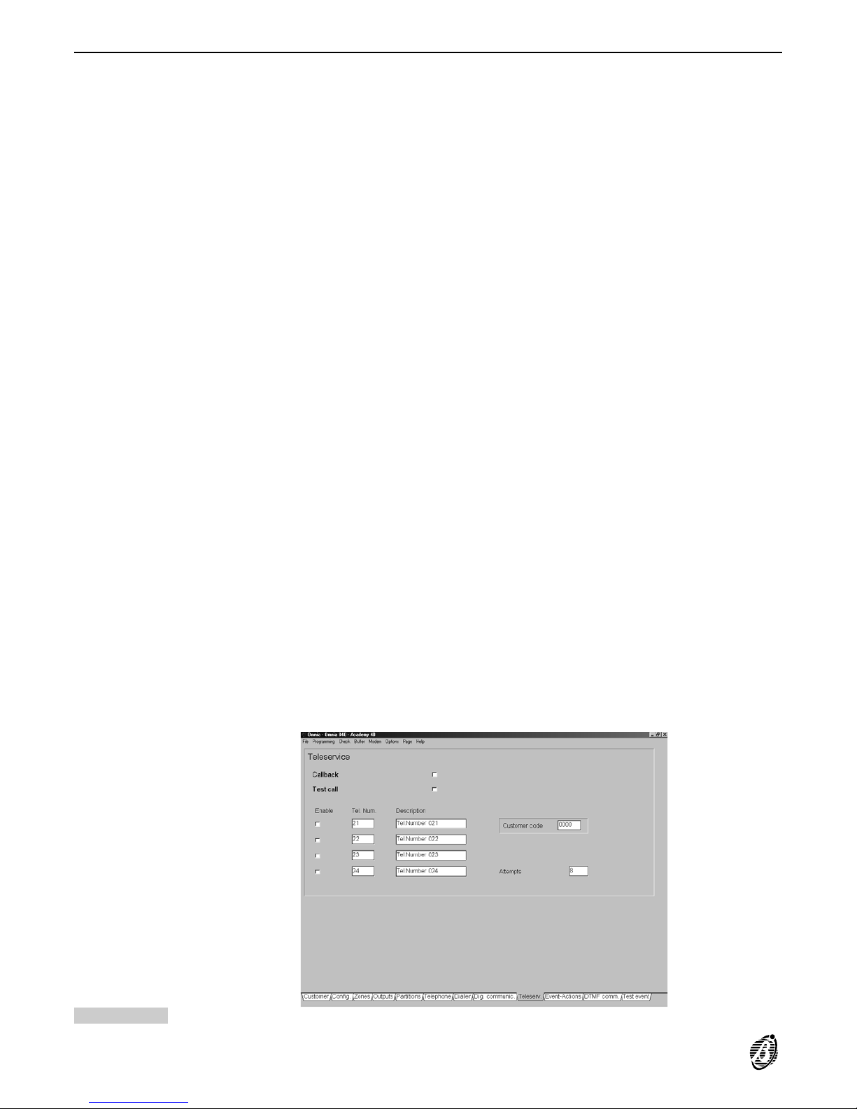
Teleservice
The B-MOD or B-MOD/RX modem, and the Omnia application from the Security Suite will allow the Installer to
teleservice Omnia Panels (e.g. change parameters via telephone).
The Teleservice call can be made by: the Installer (with user authorization); the User and the Test event (if enabled).
When the Panel generates a Teleservice call (whether manual----on User request, or automatic----by means of
Callback or Enable Test call) it will dial the enabled telephone numbers (refer to Enable) until a call is successful,
or until the programmed call Attempts cycle ends.
Callback When this option is selected the Panel will call the enabled telephone numbers (refer to Enable) in the Teleserv-
ice page (refer to Tel.Num. and Description). Thus authorized personnel only can teleservice the Panel.
Enable Test call When this option is enabled the Panel will make the Teleservice call automatically, as per the programming in the
Test event page.
+
The Test event must be enabled (refer to Test event page).
Enable Select the Teleservice telephone numbers.
Tel. Num. Assign up to 4 telephone numbers to Teleservice (enter the identifier numbers----1 through 32). The corresponding
label will be shown in the Description column.
Enable the telephone numbers for Teleservice.
+
4 telephone numbers are dedicated to Teleservice. The unused telephone numbers must be disabled and left at
default.
Customer code This code allows the Central Station to identify the Panel. Each Panel must have a different Customer code. Duplica-
tion of a Customer code will be signalled when Save is selected (full details of the current code User will be shown).
+
Changes made to the Customer code in this page will be transferred to the Customer page and vice versa.
Attempts Enter the maximum number of call attempts for failed calls.
Figure 30 Teleservice page
46 Expandable Multifunction Control Panel Omnia
Page 47
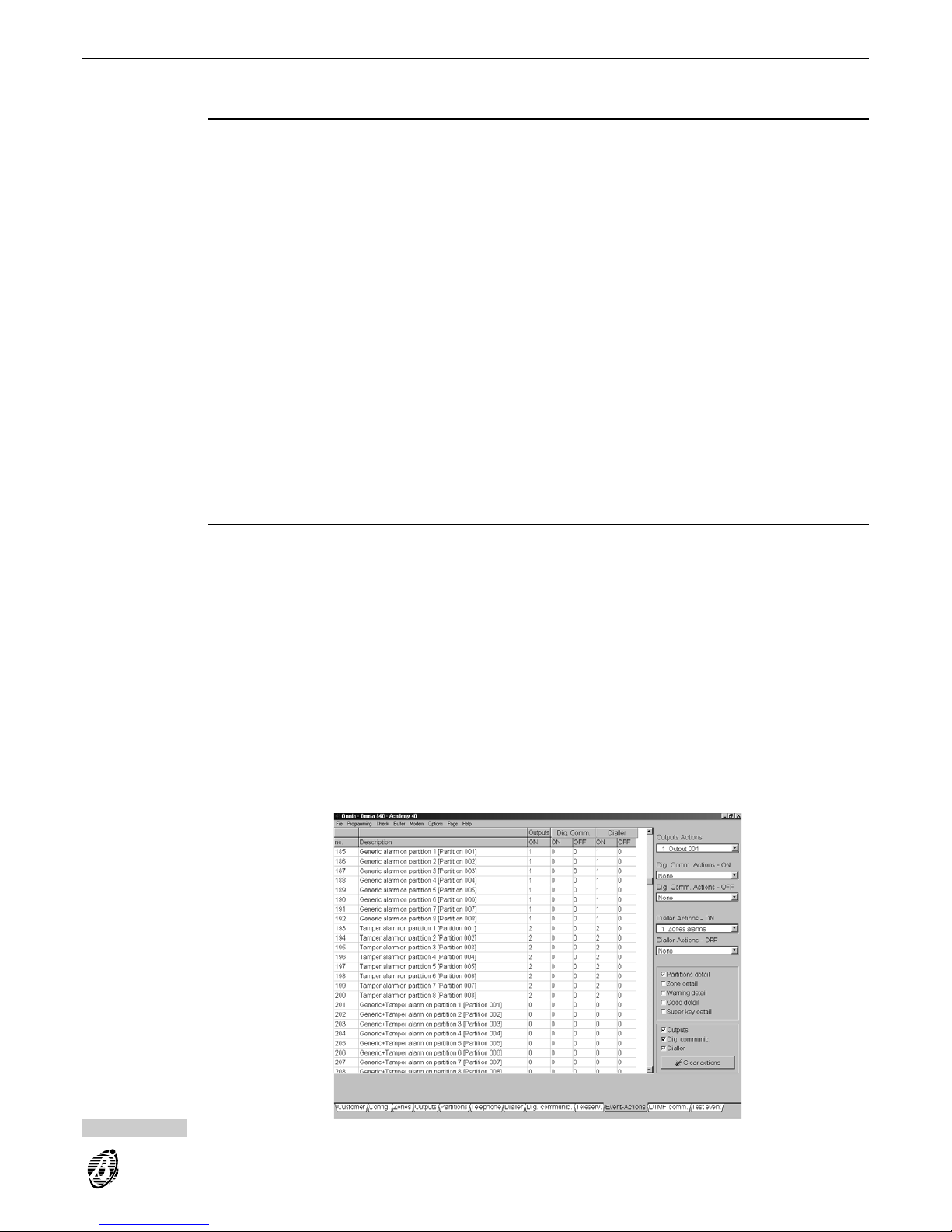
Event-Actions
The Events-Actions page is the core of the System. The Panel will operate in accordance with the programming
done in this page.
Events Table
The Output, Digital Communicator and Dialler Actions can be assigned to the Events shown.
The Events Table is set out in the following way:
no. This is the event number----to be specified in the DTMF Comm. page when assigning the corresponding event to a
DTMF Communicator channel (for Firmware versions lower than 3.0).
Description This is the event label:
----the round brackets will show the label of the peripheral of the object that generated the event;
----the square brackets will show the label of the object that generated the event.
+
The Event number will vary in accordance with the detail level selected on the right side of the page (refer to the
Events description section).
Outputs ON Enter the identifier number of the output that will be activated (refer to Outputs page) by the corresponding event.
0 = no Output will be activated
Dig. Communic. Use the ON column for the identifier numbers of the actions that will be activated by the Digital Communicator
when the corresponding event starts (refer to Dig. Communic.).
Use the OFF column for the identifier numbers of the actions that will be activated by the Digital Communicator
when the corresponding event ends (refer to Dig. Communic.).
Dialler Use the ON column for the identifier numbers of the actions that will be activated by the Dialler when the corre-
sponding event starts (refer to Dialler page).
Use the OFF column for the identifier numbers of the actions that will be activated by the Dialler when the corresponding event ends (refer to Dialler page).
Priority telephone actions
Action no.1 on the telephone Dialler and action no.1A of the DTMF communicator have priority over all other telephone actions.
These two actions have the same priority level, therefore, if one occurs whilst the other is running, the ongoing action will not be interrupted.
+
Priority telephone actions should be used for events such as Medical Emergency or Duress.
Figure 31 Event-Actions page
PROGRAMMING 47
Page 48

Actions
Using the Output Actions----Dig. Comm Actions - ON----Dig. Comm Actions - OFF----Dailler actions - ON
drop-down menus assign the Actions to the selected event,as follows:
Output action Select the Output that will be activated by the event in question.
Dig. Comm.
Action - ON
Select the Digital Communicator action that will be generated when the event starts.
Dig. Comm.
Action - OFF
Select the Digital Communicator action that will be generated when the event ends.
Dialler Actions -ONSelect the Dialler action that will be generated when the event starts.
Dialler Actions -
OFF
Select the Dialler action that will be generated when the event ends.
View event details
The Events-Actions page shows the Panel events----but not the event details. Click the relevant detail check box
to view the corresponding *Global* events.
Partition detail Select this option to view all Partition events (Alarms, Arming, etc.).
Zone detail Select this option to view all Zone events (Alarms, Tamper, Bypass etc.).
Warning detail Select this option to view all faults (trouble) events.
When deselected----only event no. 229 Warning generic will be shown (this warning represents all types faults).
Code Detail Select this option to view all events assigned to Codes on keypads.
When deselected----only the Global event no. 437 Recognized code *Global* will be shown.
Super key detail Select this option to view all Super key events.
When deselected----only the no. 397 Super keys *Global* event will be shown.
+
No actions can be assigned to *Global* events----a s this is the label of the virtual events that will not be shown for
the selected detail level.
The word None in the Outputs, Dig.Comm. and Dialler columns means:
----none of the *Global* events has an action of the corresponding type.
The Act.Pres. string in the Outputs, Dig.Comm. and Dialler columns means:
----one or more *Global* events has an action of the corresponding type.
Clear actions
Click Clear actions----in the Outputs, Dig.Comm. and Dialler sections----to delete the corresponding Actions, as
per below.
Outputs Select the Outputs check box then click Clear actions to clear all Output actions.
Dig.Comm. Select the Dig.Comm. check box then click Clear actions to clear all Dig.Comm. actions.
Dialler Select the Dialler check box then click Clear actions to clear all Dialler actions.
+
The Panel will ask for confirmation before clearing the selected actions.
Events description
Following is a description of the conditions that generate (or stop) the various events. Please note that in some
cases the event will not end when the cause of the alarm ends.
Alarm events
Alarm events will be generated by alarm status at zone, partition, or Panel level.
The Zone Events are the lowest level of Alarm events. They are linked to alarm and tamper status on the corresponding zones.
The Partition and Panel Events are the "OR" logic of the Zone Events.
+
All alarm events will end when the cause of the alarm ends, unless assigned to monostable outputs.
Events----assigned to monostable outputs----will end when the programmed On time of the assigned output
elapses.
The programmed On time will run its full time, even if the cause of output activation has been cleared.
These events will not be generated during the programmed Off Time of the assigned output, or when the assigned
monostable output is active.
If an alarm event is assigned to a Monostable output (Siren) with a 3-minute On time, the 3-minute cycle will run
its full time, even if the cause of alarm has been cleared. However, the Alarm Event will end immediately if the
Panel is disarmed.
48 Expandable Multifunction Control Panel Omnia
Page 49
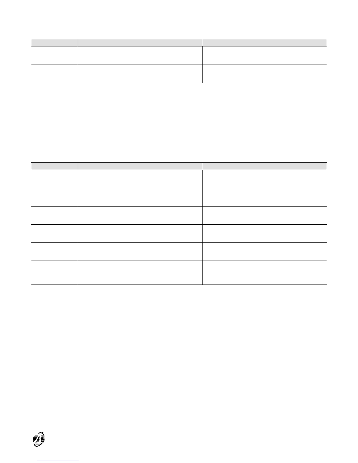
+
The ENDS WHEN... column in the following table is valid for events that are not assigned to monostable outputs.
Zone events
EVENT OCCURS WHEN ... ENDS WHEN ...
1
:
80
Alarm on
zone no.
... the zone is in alarm status ... the zone returns to standby status
81
:
16
Tamper on
zone no.
... the zone is in tamper status ... tamper status on the zone ends
* The conditions causing the zone alarm and tamper are described in the {Zones} page.
These events can be forced into standby status by:
changing the status (Arm/Disarm) of the partition the zone is assigned to;
resetting the partition the zone is assigned to;
using a key/card at a reader (both objects must be enabled on the partition);
entering a User code on a keypad, and selecting the Stop alarm option (both User code and keypad must be en-
abled on the partition).
Partition Events A Partition Event will be generated when an event occurs on one of the zones (Zone Event) assigned to the Parti-
tion, and will end when all the zone events cease, as follows.
EVENT OCCURS WHEN ... ENDS WHEN ...
161
:
168
Fire alarm on
partition no.
... a Fire zone----assigned to the partition is in alarm
status
... all events generated by the Fire zones----assigned to
the partition return to standby status
169
:
176
24h alarm on
partition no.
... a 24h zone----assigned to the partition is in alarm
status
... all events generated by the 24h zone----assigned to
the partition return to standby status
177
:
184
Burglar
alarm on
partition no.
... a burglar zone (Instant, Entry delay, Entry path,
Exit delay or Last exit zone)----assigned to the
partition is in alarm status
... all events generated by the burglar zones----assigned
to the partition return to standby status
185
:
192
Generic
alarm on
partition no.
... a zone (any Type)----assigned to the partition is in
alarm status
... all Alarm events generated by the zones----assigned
to the partition return to standby status
193
:
200
Tamper
alarm on
partition no.
... a zone----assigned to the partition is in tamper status
... all Tamper events generated by the zones---assigned to the partition return to standby status
201
:
208
Generic+
Tamper
alarm on
partition no.
... a zone----assigned to the partition is in alarm or
tamper status
... all events (Alarm and Tamper) generated by the
zones----assigned to the partition return to standby
status
To force these events into Standby status:
change the partition status
reset the partition
use a key/card at a reader (the key/card and reader must be enabled on the partition)
enter a User code at a keypad, and select the Stop alarm option (both User code and keypad must be enabled on
the partition).
PROGRAMMING 49
Page 50
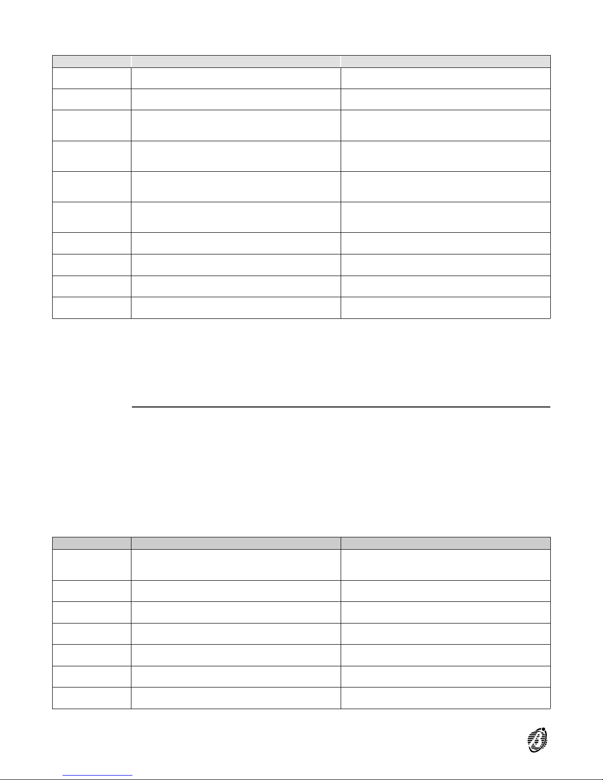
Panel Events A Panel Event will be generated when the corresponding event type occurs on any zone----whatever the partition,
and will end when all the corresponding types of zone events cease, as follows.
EVENT OCCURS WHEN ... ENDS WHEN ...
209
Fire alarm on
panel
... a Fire zone----assigned to any partition is in alarm
status
... all events generated by the Fire zones----o f al l
partitions----retu rn t o standby status
210
24h alarm on
panel
... a 24h zone----assigned to any partition is in alarm
status
... all events generated by the 24h zones----of all
partitions----retu rn t o standby status
211
Burglar
alarm on
panel
... a burglar zone (Instant, Entry delay, Entry path,
Exit delay or Last exit zone)----assigned to any
partition is in alarm status
... all events generated by burglar zones of all partitions
return to standby status
212
Generic
alarm on
panel
... any zone----assigned to any partition is in alarm
status
... all Alarm events generated by the zones of all
partitions return to standby status
213
Tamper
alarm on
panel
... any zone----assigned to any partition is in tamper
status
... all Tamper events generated by the zones of all
partitions return to standby status
214
Generic+
Tamper alarm
on panel
... any zone----assigned to any partition is in alarm or
tamper status
... all events (Alarm and Tamper) generated by the
zones of all partitions return to standby status
215
Tamper on
Main unit
... the tamper switch (2) or snatch switch (15) in the Main
unit opens
... the tamper and snatch switches close
216
Balanced
tamper
... terminal [ASB] is unbalanced
... terminal [ASB] is balanced (connected to ground with
a 10,000 ohm-resistor)
217
Tamper on
BPI device
... a tamper or snatch switch of a BPI peripheral opens
(Keypads, Input or Output Expanders, etc.)
... all tamper and snatch switches of BPI peripherals
are closed
218
False key at
reader
... A false key/card at a reader ... false key/card is no longer detected
These events can be forced into standby status by:
entering (at any keypad) a User code enabled for Panel Reset, and selecting the Alarm reset option;
entering (at any keypad) a User code enabled for Panel Reset and selecting the Stop alarm option;
using a valid key/card at a reader. The Enable Stop alarm on panel with valid key option must be enabled (refer
to Options from the Programming menu).
Generic Events
These events will be generated by the Panel, and do not have a start or end condition (e.g. No Mains).
Generic Events can be forced into standby status by using an enabled User Code (at any keypad) to activate the
Reset Alarm command.
If these events are assigned to a monostable output they will behave as follows.
If the generating condition is still present after the On time of the out put ----th e la tter will return to standby status
but the event will not end until the condition ceases.
If the generating condition ends before the On time of the Monostable output has elapsed, the output will return
to standby status, and the event will end.
When these events are not assigned to a Monostable output, they will end when the conditions in the following
table occur.
EVENT OCCURS WHEN ... ENDS WHEN ...
219 Global alarm
memory
... any type of alarm or tamper is detected (Zone alarm
or tamper, Open panel, Balanced tamper, BPI
peripheral tamper, False key/card at reader)
... the alarm memory is cleared by Partition Reset or
Panel Reset
220
Warning fuse
+F
... Fuse 21 blows ... fuse 21 is replaced
221
Warning fuse
+B
... Fuse 20 blows ... fuse 20 is replaced
222
Warning fuse
BPI1
... Fuse 18 blows ... fuse 18 is replaced
223
Warning fuse
BPI2
... Fuse 19 blows ... Fuse 19 is replaced
224
Warning
mains failure
... after mains power failure for the programmed time
(refer to Filter times in the Programming menu)
... the mains power supply is restored
225
Warning low
battery
... mains power failure and insufficient battery power for
Panel functioning
... the battery charge is above the safety limit
50 Expandable Multifunction Control Panel Omnia
Page 51

EVENT OCCURS WHEN ... ENDS WHEN ...
226
Warning
power trouble
... the battery is unable to supply the Panel properly
(calculated with mains present only).
... the battery or the protection fuse 27 is replaced
227
Warning
mains failure
on Power
station
... the power supply of one of the Power stations on
the BPI Bus fails for the programmed time (refer to
Filter times in the Programming menu)
... the mains power supply is restored on all the Power
stations on the BPI Bus
228
Warning low
battery on
Power station
... mains power supply fails to one of the Power stations
on the BPI and the battery cannot supply the peripherals
properly
... the Power station battery charge reaches the
required level
229
Warning
power
trouble on
Power station
... the battery of one of the Power stations on the BPI
Bus is unable to supply sufficient power to the
peripherals
... the battery (or the protecting fuse) is replaced
230
Warning
generic
... one of the previously described troubles starts ... all previously described troubles end
231
Trouble on
BPI
... the Main unit cannot find one or more of the BPI
peripherals, due to trouble or tamper
... the Main unit finds all the BPI peripherals in the BPI
Bus configuration
232
:
239
partition no.
armed
... the partition is armed ... the partition is disarmed
240
:
247
Exit time on
partition no.
... the partition is armed
... the programmed Exit time of the partition elapses,
unless, a Last exit zone is violated during the Exit
time, in which case it will end after the programmed
Last exit time of the partition
248
:
255
Entry time on
partition no.
... an Entry delay zone----assigned to the armed
partition is violated
... the programmed Entry time of the partition elapses
or when the partition is disarmed
256
:
263
Valid key on
partition no.
... the key/card and reader in use are enabled on the
partition
... the key/card is removed from the reader
264
Valid key on
panel
... a valid key/card is used at a reader ... there are no valid keys /cards at readers
265
:
272
Stop alarm
on partition
no.
... a Stop alarm request made by an enabled User code is
done on a keypad----enabled on the partition
... alarms are no longer blocked
273
Stop alarm
on panel
... a Stop alarm request made by a User code----enabled
for this option
... alarms are no longer blocked
274
:
353
Bypass zone
no.
... the zone is bypassed ... the zone is unbypassed
354
:
361
Not ready to
arm partition
no.
... there is alarm status on at least one zone, that is not
a delayed, last exit, bypassed or command type zone.
The calculation occurs every 2 seconds
... the alarm status ends on all the not delayed, last exit,
bypassed or command type zones
362
Telephone
line trouble
... the voltage on the telephone line drops below 3 V for
at least 45 seconds. This event will not be generated
when the Disable telephone line check option is
enabled
... the proper voltage (over 3 V) is restored for at least
15 seconds
363
:
370
Autoarming
warning
partition no.
... the OmniaTIMER generates the Autoarming warning
for the partition
... the OmniaTIMER arms the partition
371
Error serial
printer
... the printer connected to the serial port on the
OmniaTIMER is out of service
...the printer connected to the serial port on the
OmniaTIMER is in service
372
Error parallel
printer
... the printer connected to the parallel port on the
OmniaTIMER is out of service
...the printer connected to the parallel port on the
OmniaTIMER is in service
373
:
380
Timer no.
The Timer (controlled by the OmniaTIMER) reaches the
programmed On time
The Timer (controlled by the OmniaTIMER) reaches the
programmed Off time
PROGRAMMING 51
Page 52

Spot events
Spot events have no END status, therefore, cannot be:
assigned to bistable outputs;
assigned to reset actions of the Dialler and the Digital Communicator;
assigned to channels of the DTMF communicator (for Firmware Versions lower than 3.0).
EVENT OCCURS WHEN ... ENDS WHEN ...
381 Test ... programmed in the Test event page
382
:
389
Reset on
partition no.
... Alarm reset is done on a keypad----enab led on th e
partition ----by a User code----enabled on the partition
390
Reset on
panel
... Alarm reset is done by a User code----enabled for
this option
391
:
400
Super key no. ... the button (key)is pressed for more than 3 seconds
401
:
408
Chime on
partition no.
... a Chime zone----assigned to the disarmed partition is
violated
409
:
439
Recognized
User code no.
... the PIN of the enabled User code is entered
440
Recognized
Installer code
... the Installer PIN is entered. This event will not
generate actions as access to the Installer menu
stops all actions
441
Teleservice
request from
B-Mod
.. a Teleservice call coming from B-MOD is answered
442
TeleserviceON... Teleservice is activated after acceptance of the
Installer PIN
443
Teleservice
action failed
... test call or Teleservice action fails (requested by the
User)
444
Failed DTMF
Communicator
action
... an action fails on the DTMF communicator---programmed to call the Central station with Contact ID
protocol
445
Failed Dialler
action
... an action fails on the telephone dialler
446
Failed Digital
Communicator
action
... a Digital Communicator action fails
52 Expandable Multifunction Control Panel Omnia
Page 53
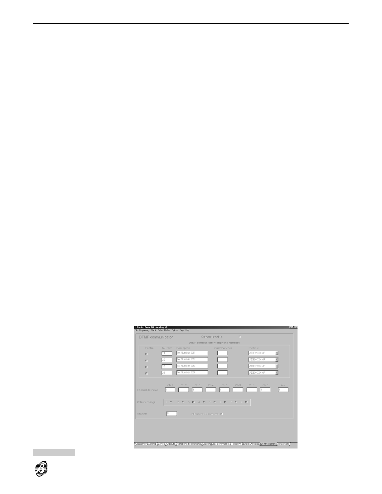
DTMF communicator (for Firmware Versions lower than 3.0)
The DTMF communicator (for Firmware versions lower than 3.0) can transmit 8 events----plus 1 of the events managed by the Panel----t o Central Stations that support this protocol.
If the status of a programmed event changes, the Panel will call the enabled telephone numbers (refer to Enable),
and will send the assigned Customer code. This will allow the Central station to identify the Panel and check the
status of the 9 channels of the DTMF communicator.
General enable Use this option to enable/disable the DTMF communicator.
Enable Enable the DTMF communicator telephone numbers.
Tel. Num. Enter the identifier number (1 through 32) of the Central station telephone number. The corresponding label will be
shown automatically.
Customer code Enter a 4 digit code (accepted digits 0 through 9). This code is usually assigned by the Central Station.
Protocol Select the protocol used by the Central station.
This Panel supports:
ADEMCO MF
SCANTRONIC MF
Channel definition Enter the identifier number of the event that will be monitored by the corresponding service (e.g. Central station).
Channel reversal All channels----except the Aux channel----can be programmed with Logic reversal. In this way, the alarm code will
be transmitted when the event ends, and the reset code will be transmitted when the event assigned to the channel starts.
Attempts Enter the maximum number of attempts for failed calls.
Call successful
numbers
At default the DTMF communicator will stop after the first successful call.
+
If this option is selected, all the telephone numbers will be dialled until they are all successful, or for the programmed number of Attempts.
Figure 32 DTMF Communicator page
PROGRAMMING 53
Page 54
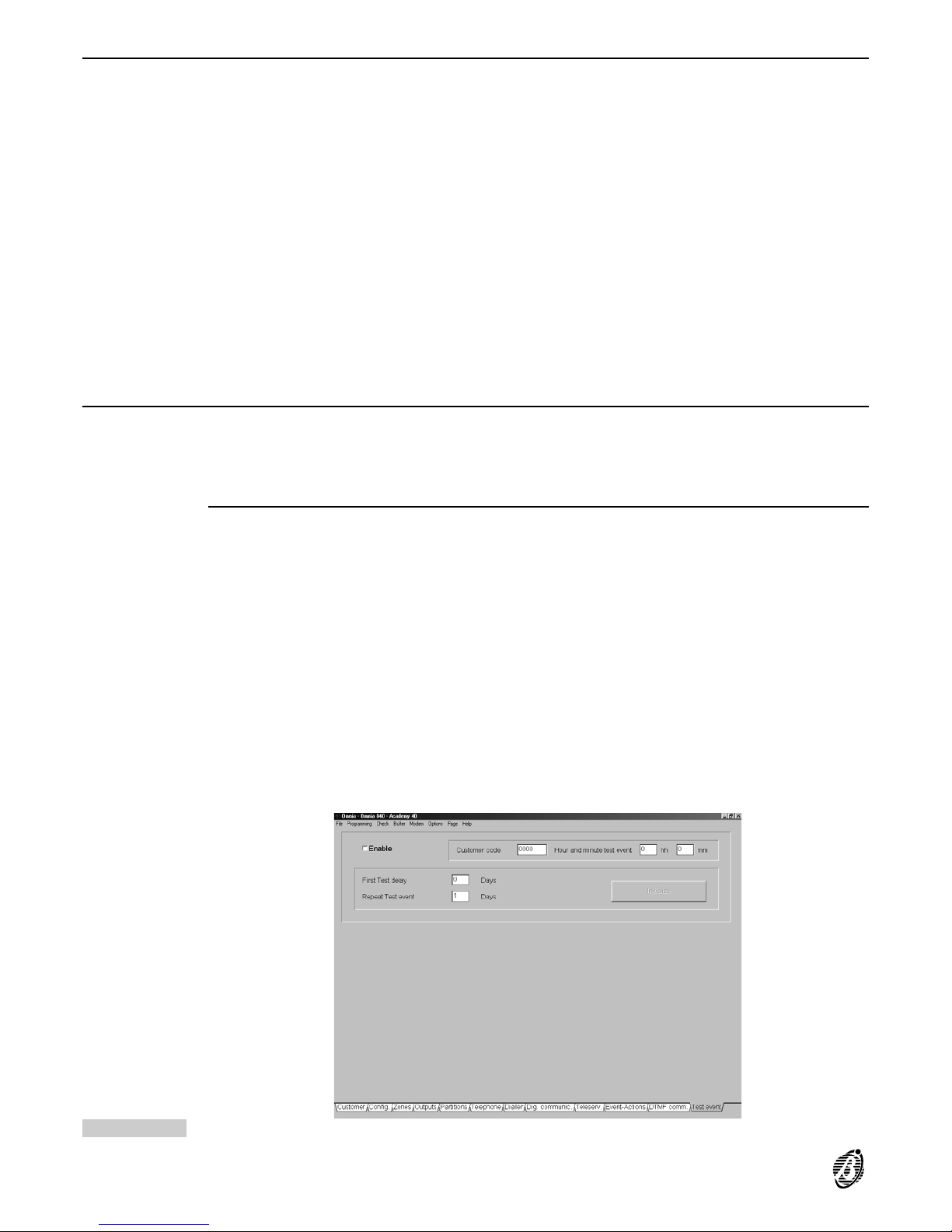
Test event
The Test event will occur as per the following parameters, and can be assigned to actions in the Event-Actions
page.
Enable Use this option to enable the Test event.
Hour and minute
test event
Enter the scheduled time of the Test event (refer to Clock from the Programming menu).
Accepted values for hh----0 through 23 (hour).
Accepted values for mm----0 through 59 (minutes)
00 in the hh field will be read as midnight.
First Test delay Enter the number of times the Panel must ignore the scheduled hour before activating the Test event. This pa-
rameter determines the number of days that must elapse before the first Test event (the day count will start when In-
itialize is selected).
Repeat Test event Specify how often the Test event must be activated.
Initialize Download the Test event parameters to the Panel (select Download Page from the Programming menu) then
click Initialize.
Click Initialize when new Test event parameters are downloaded to the Panel.
+
The Panel must be connected to the computer (via RS232 or telephone), otherwise, the program cannot initialize
the system.
Keypad Codes
The Codes (User and Installer Codes) and keys operate the system. The Panel has a total of 32 Access Codes.
Access Codes 1 through 32 correspond to default Code PINs 0001 through 0032.
+
By default Code 1 is already Available, and is also Master of all Codes----including itself (refer to Code Attributes
programmed by the Installer).
User Code Description
Enable on
partitions
Keypads and User codes can be enabled on specific partitions (refer to Config. page for keypad partitions). User
codes operate enabled partitions only (User code partitions), and the matching partitions on the keypad in use
(Keypad partitions). Therefore, the effect of a User code request also depends on the keypad. This dual level of
control facilitates use, as the same operation can have different effects on different keypads.
Example
User code enabled on partitions 1, 5 and 7 entered at a Keypad enabled on partitions 1, 4, 7 and 8.
The User code request will effect partitions 1 and 7----as partition 5 is not a keypad partition, and partitions 4 and 8
are not User code partitions.
Recognized User
code event
Code acceptance will generate the Recognized User code no. event. This event can be assigned to an output or
telephone action. Proper programming of events and outputs eliminates trouble linked with access control and/or
limitations (refer to the Recognition of multiple codes section in the FACILITIES section).
Figure 33 Test Event page
54 Expandable Multifunction Control Panel Omnia
Page 55

Code attributes programmed by the Installer
The attributes determine how the User code can operate the system (refer to Enable on Partitions----Enable user
menu ----Enable instant actions).
Available Only Available User codes can operate the system.
The system usually requires less than the 31 User codes provided. This time-saving option allows the Installer to
make only the required number of User codes Available to operate the system. Without this option it would be
necessary to change all the default PINs for security reasons.
+
If a User code has been programmed but has not been made Available, it will be considered inexistent.
Master code ---- All User codes must have a Master code.
----User codes with Master status will become Available and Active automatically.
----The Available and Active status of Master codes cannot be disabled.
----User codes 1 through 24 can be Master codes.
----User codes 25 through 31 cannot be Master codes.
----A code can be its own Master, and therefore, can change its own PIN.
----A code can be Master of several codes but Slave of only one.
----Only a Master code can disable the Active status and PIN of its Slave code.
----A Slave code must be disabled by its current Master code before it can be assigned a new Master code (refer
to User parameters).
+
The Installer cannot disable the Available status of an Active User code via computer.
User Parameters
These parameters are usually programmed by the User. However, if Installer intervention is preferred, the User
must provide the Installer with the Master code PIN.
Active: this option allows the Installer to disable a User code via computer (Master code PIN required).
PIN: this option allows the Installer to change a User code PIN via computer (Master code PIN required).
Enable on
partitions
Enabled User codes can control: Arming/Disarming, Stop Alarm and Bypass zone operations on their partitions.
Yes = User code Enabled on the corresponding partition
Box clear = User code disabled on the corresponding partition
Row A is for the partitions that will arm (A) or disarm (D) when the User code is entered at a keypad, and is
pressed (Type A arming mode).
Row B is for the partitions that will arm (A) or disarm (D) when the User code is entered at a keypad, and is
pressed (Type B arming mode).
The enabled partitions will arm or disarm when the User code is entered at a keypad, and or is pressed.
Enable User menu The User menu will provide the enabled options only. Enable/Disable the following options, as per requirements.
Arm/Disarm: arms/disarms partitions separately
Panel reset: resets/stops alarms on panel
Partitions reset: resets/stops alarms on partitions
View/Bypass zones: views/bypasses zones
View: views the event buffer
Teleservice: teleservice
Clear call queue: clears telephone-call queue
Output management: enables /disables outputs
The enabled options will be shown on the corresponding User menu. However, in particular instances the Teleserv., Panel reset and Partition reset will perform as follows.
+
If Teleservice is disabled the Teleserv., En./Dis.Teleser. and En./Dis.Answer options will not appear on the
User menu.
Enablement of the Panel reset and Partitions reset options determines the actions the Panel will perform when
Alarm reset or Stop alarm is selected from the User menu.
A
#
B
PRGONRES
OFF
PROGRAMMING 55
Page 56

Alarm reset from
User Menu
If the Alarm reset option is selected by a User code enabled for Panel reset----i t will:
Delete alarm memory----Main unit open, balanced tamper, Tamper on BPI device and false key/card at reader.
Force to Standby----the Outputs activated by the following events.
Fire alarm on panel Generic+Tamper alarm on panel
24h alarm on panel Tamper on Main unit
Burglar alarm on panel Balanced tamper
Generic alarm on panel Tamper on BPI devices
Tamper alarm on panel False key at reader
If the Alarm reset option is selected from by a User code enabled for Panel reset and Partition reset----it will perform as per above (Alarm reset) and will also:
Delete alarm memory----for partition alarm and tamper.
Force to Standby----the Outputs activated by the following events.
Fire alarm on partition Generic alarm on partition
24h alarm on partition Tamper alarm on partition
Burglar alarm on partition Generic+Tamper alarm on partition
Stop alarm from
User Menu
When the Stop Alarm option is selected by a User code enabled for Panel reset----it will:
Force to Standby----the Outputs activated by the following events.
Fire alarm on panel Generic+Tamper alarm on panel
24h alarm on panel Tamper on Main unit
Burglar alarm on panel Balanced tamper
Generic alarm on panel Tamper on BPI devices
Tamper alarm on panel False key at reader
If the Stop alarm option is selected by a User code enabled for Panel reset and Partition reset----it will perform
as per above (Stop alarm) and will also:
Force to Standby----the Outputs activated by the following events.
Fire alarm on partition Generic alarm on partition
24h alarm on partition Tamper alarm on partition
Burglar alarm on partition Generic+Tamper alarm on partition
+
Alarm reset and Stop Alarm requests will effect the User code partitions only. Therefore, if an output is assigned
to two partitions----and one of the two is not an enabled partition of the User code entered at the keypad----the output will remain active until a Stop alarm request is made for both partitions.
+
An Output will return to Standby status automatically when all the activating events end. Alarm reset and Stop
Alarm requests will effect the User code partitions only.
Enable Instant
actions
The USER MENU also provides extra User code options, as follows.
Arming type A: enter the User code then press
Arming type B: enter the User code then press
Arm enabled partitions: enter the User code then press
Disarm enabled partitions: enter the User code then press
Enable scheduler: enable the Scheduler
*1 - Enable/Disable via DTMF: code enable/disable via DTMF
*2 - Inputs status via DTMF: Input reading via DTMF
*3 - Remote listen-in----Telephone func: remote listen-in and 2-way communication (via telephone)
* The last 3 actions (*1, *2 and *3) are provided by DTMF commands via telephone.
Refer to the TELEPHONE OPERATIONS section in the USER MANUAL under:
----Enable/Disable via DTMF and Inputs status via DTMF for *1 and *2; ----Remote Listen-in----Telephone func.
for *3.
A
#
B
PRG
ON
RES
OFF
56 Expandable Multifunction Control Panel Omnia
Page 57
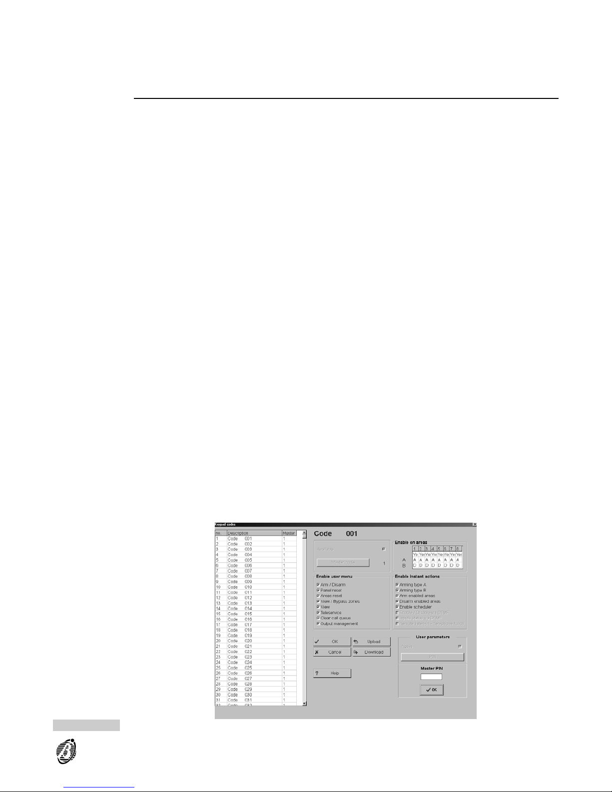
User codes 25 through 31 are enabled for these options (OmniaVOX module required).
If a User code is enabled for Scheduler management----the User Menu will provide the Overtime request option,
thus allowing the User to delay the programmed arming time.
If the code is also enabled for Panel reset----the User Menu will provide the Auto-arm En/Dis. option, therefore, the
code can enable/disable the auto-arming/disarming operations controlled by the Timer.
Programming Access Codes
Please note that improper programming of Codes may impair security, therefore, the instructions must be followed
carefully. The following notes may be helpful.
Step 1 Select Keypad codes from the Programming menu then select a Code from the Keypad codes table.
Step 2 Enter the User label (up to 16 characters) under Description----then click the Code Identifier number. The window
will be dedicated to the selected Code.
Step 3 Make the code Available (top centre of window).
+
Codes that are not Available cannot operate the system.
Step 4 Click Master (top centre of window) then enter the identifier number (1 through 31) of the new Master code. Click
OK to confirm. The Master code identifier number will be shown in the Master column of the Keypad codes table,
and also next to the Master Code button.
Step 5 Enable/Disable the Code on Partitions 1 through 8 (top row). Double click to toggle the status.
Yes = Code Enabled on the corresponding partition
Box Clear = Code Disabled on the corresponding partition
Step 6 Select the partitions that will Arm/Disarm when the Code makes a Type A arming request (row A). Double click to
toggle the status.
Select the partitions that will Arm/Disarm when the Code makes a Type B arming request (row B). Double click to
toggle the status.
Step 7 Enable the User menu options.
Step 8 Enable the Instant Actions.
+
The Enable/Disable via DTMF----Inputs Status via DTMF----Remote listen-in - Telephone func. options apply
to User codes no. 25 through no. 31 only.
Step 9 Click OK to confirm the programmed parameters.
+
The Installer Code label can be assigned in the Keypad codes page. Select the Installer code option from the
Programming menu to program the Installer Code PIN (Code 32).
Figure 34 Codes page
PROGRAMMING 57
Page 58
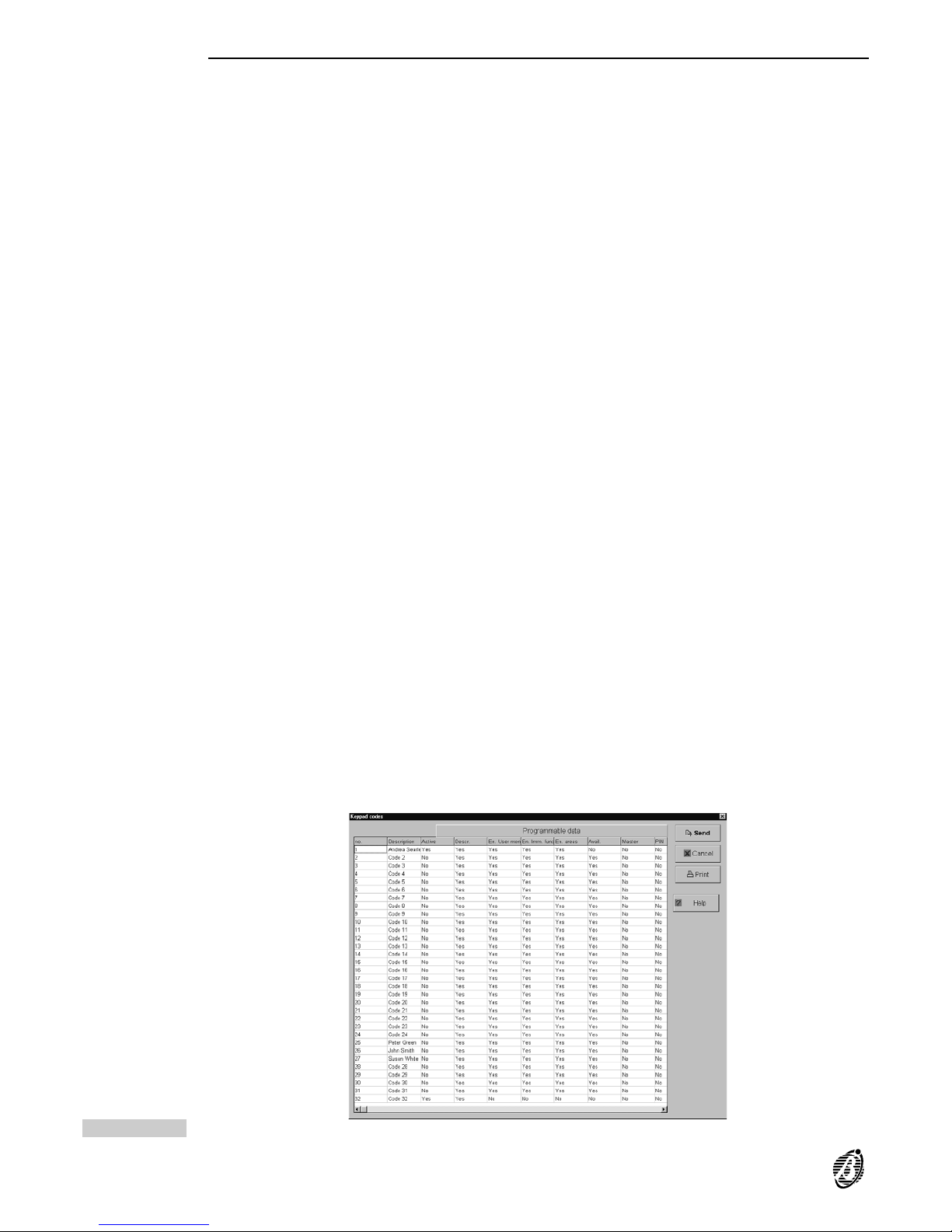
Attributes programmed by the user
Only Master codes can program and change the following attributes of their Slave codes.
PIN The User code PIN (Personal Identification Number) can have 4, 5 or 6 digits.
Active
Disabled
An Active User code can operate the system. A Master code can disable its Slave codes.
Disabled User codes will not be recognized by the Panel, and therefore, will be unable to operate the system.
Master codes cannot be disabled.
Download Select to download the programmed data to the Panel.
Upload Select to upload programmed data from the Panel to the computer.
The data that will be downloaded depends on whether or not the User PINs in the computer memory match those
in the Panel memory----as follows.
PINs Match The User code PINs are either at default, or have been uploaded from the Panel. Therefore, all the parameters
programmed in the Keypad codes page will be downloaded.
Pins Mismatch The User code PINs are not at default, or have not been loaded. Therefore, the following data will be downloaded:
Description
Available: if the User code in the Panel memory is disabled (not Active).
Enable User menu
Enable on partitions
Enable instant actions
Figure 35 Keypad codes page
58 Expandable Multifunction Control Panel Omnia
Page 59

Keys
Select Digital keys from the Programming menu to open the Digital keys window then program as follows.
no. This is the identifier number used during key programming via keypad.
Description Assign the identifier label to the key in this field (maximum 16 characters). The label will be used as the key identifier.
En. Use this attribute to enable the key. The Panel will consider Disabled keys as false.
1..8 Assign the keys to the partitions.
Select Download to transfer data to the Panel.
Select Upload to transfer data from the Panel to the computer.
Super keys
Select Super keys from the Programming menu to open the Super keys window. Keys 0 through 9 will take on
Super key status when pressed for approximately 3 seconds. Program the Super keys as follows.
Assign a label (maximum 16 characters) to each Super key.
no. This is the Super key identifier number from 1 to 10 ( corresponds to 10).
Description Enter the Super key label (maximum 16 characters).
Select Download to transfer data to the Panel.
Select Upload to transfer data from the Panel to the computer.
Filter times
Select Filter times from the Programming menu to open the Filter times window then program the Mains parameter----all other parameters are non-modifiable.
Mains Enter the number of seconds that must elapse before Mains failure is signalled. Accepted values: 0.3 sec. through
3,600 seconds (= 1 hour) in steps of 0.1 second. Event no. 223 Warning Mains failure will be generated when the
programmed delay elapses.
0
PROGRAMMING 59
Page 60
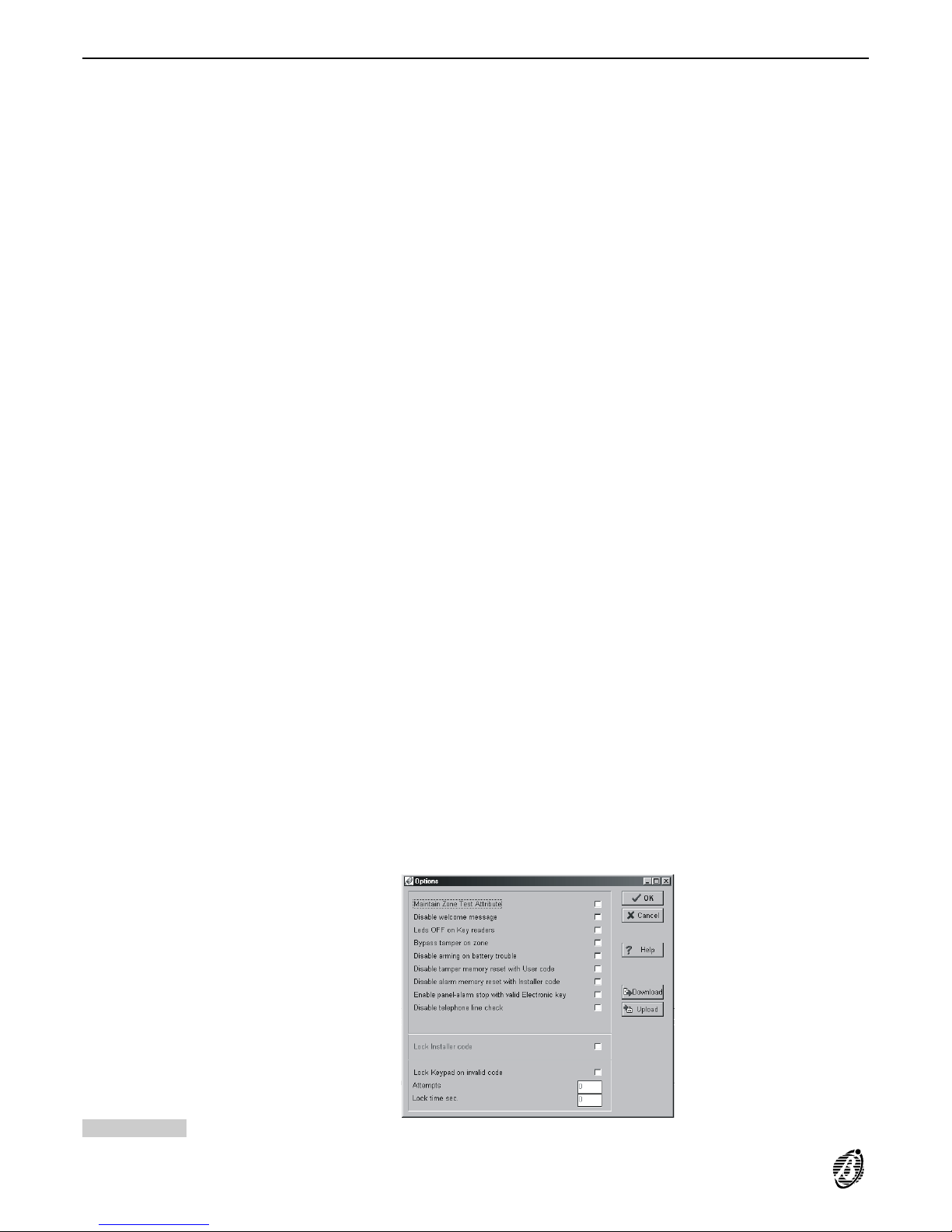
Options
Select Options from the Programming menu to open the Options window then program as follows.
Maintain Zone
Test Attribute
Option enabled----the Zone Test attribute will be active even when the partition is disarmed, therefore, zone alarms on
Test zones will be logged in the event buffer.
Disable welcome
message
Option enabled----the welcome message will not be displayed----even in response to a valid User code.
LEDs OFF on
readers
Option enabled----the three reader LEDs will be OFF if no valid key/card is present.
Bypass tamper
on zone
Option enabled----tamper will not generate an alarm when the zones are bypassed.
Disable arming
on battery trouble
Option enabled----arming requests will be denied when there is battery trouble on the Main unit or on the connected Power stations, especially for the following events:
----Low battery warning
----Power trouble warning
----Low battery on power station warning
----Power station trouble warning
Disable tamper
memory reset
with User code
Option enabled----User codes cannot reset the zone, partition and Panel tamper alarm memory, this can be done
by the Installer code only.
Disable alarm
memory reset
with Installer code
Option enabled----t he a larm memory cannot be reset by the Installer, this can be done by enabled User codes
only.
Enable Stop
panel alarm with
valid key
Option enabled----Panel alarms can be stopped by using a valid key/card at a reader.
Disable telephone
line check
Option enabled----the Panel will not signal telephone line trouble (e.g. Line down). The Telephone line trouble
event will not be signalled at any time. This option must be enabled, when the Panel is not connected to the telephone line, otherwise, the Telephone Line Trouble event will be logged repeatedly in the Event Buffer (refer to
Options in the PROGRAMMING section).
Lock Installer
code
Option enabled----reset of Factory default programming will not default the Installer PIN (refer to Installer Code
section).
Lock Keypad on
invalid code
Option enabled----keypad lock-out will occur after the programmed number of wrong code entries.
Attempts This is the number of wrong codes allowed before lock out: accepted values 1 through 10.
Lock time sec. This is the keypad lock-out time (in seconds): set 9 through 1,800 seconds.
Figure 36 Options page
60 Expandable Multifunction Control Panel Omnia
Page 61

Scheduler
The OmniaTIMER parameters can be programmed via the Scheduler option from the Programming menu (refer
to the OmniaTIMER section).
LCD strings
Select the LCD strings option from the Programming menu to change the Welcome message and language
(LCD strings) on the keypads. The Welcome message will be shown in response to valid User code PINs.
Change Welcome
message
Enter the new message in the Welcome message space (max. 16 characters) then Select Download to the
Panel.
+
The message will not be changed if Download is selected when the Welcome message space is empty, therefore,
the message will be as per default.
Click Global download to download all the LCD messages to the keypads in the language used in the application
(refer to Language----Options menu).
+
Download and Global Download cannot be used until the Panel is connected to the computer----via serial cable.
Clock
Proper functioning of the Scheduler depends on the clock setting, therefore, the Clock must be set with precision.
Setting Select Clock from the Programming menu then select the exact time: Hour, Minute, Day, Month and Year.
Date format dd/mm/yyyy = Day / Month / Year
yyyy/mm/gg = Year / Day / Month
Separators
Select the date separator (colon (:) or slash (/)). The date format and selected separator will be used on the keypads.
Installer code
The Installer code PIN allows the Installer to program the Panel parameters via local/remote connection, and access the INSTALLER MENU from the keypad. The Installer code PIN is also required for downloading.
By default the Installer code PIN is 0032. Select the Installer code option from the INSTALLER MENU (at keypad) to change the Installer code PIN.
Current PIN Enter the current Installer Code PIN under Current PIN (Installer code window) to download. If a wrong PIN is en-
tered the data will not be downloaded to the Panel.
Change PIN Enter the current Installer Code PIN under Current PIN then enter the new PIN under New PIN and Check new
PIN. Click Download to the memorize the New PIN on the Panel.
Lost Installer
code PIN
If lost, the Installer code PIN can be reset to default (refer to the Reset default section). However, if the Installer
code PIN is locked it will be necessary to call your dealer (refer to Lock Installer code in the Options section).
PROGRAMMING 61
Page 62
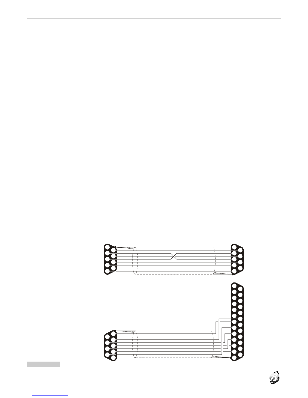
On-site Downloading from computer
Download the programmed parameters as follows (Installer Code PIN required).
Step 1 Connect a computer serial port to the Panel serial port (6) by a CVSER/9F9F serial cable (optional) or make the
cable as per Figure 37a.
If the computer has 25 pin serial-port connector----use an ADSER/9M25F adapter (optional) or make the cable as
per Figure 37b.
Step 2 Select Serial ports from the Options me nu----then select the serial port (Panel section) used for the connection to
the Panel. Click OK to confirm.
Step 3 Select Installer code from the Programming window----then enter the Installer Code PIN in the PIN section. Click
OK to confirm.
Step 4 Open the Customer page----then select the corresponding Panel type. Click OK to confirm.
Step 5 Select Firmware release from the Options menu----then select the corresponding release. Click OK to confirm.
Step 6 Use the Download option from the Programming menu to download specific Page data or All programming data
to the Panel.
Full On-site download will take approximately 3 minutes.
Use the Upload option from the Programming menu to upload and view specific Page data or All programming
data from the Panel.
+
The selected firmware release must match the Panel firmware release. The firmware release can be viewed on
the display of any keypad by selecting Revision from the Installer Menu.
5
4
6
5
4
3
2
1
9
18
8
19
17
16
15
14
7
20
21
22
23
24
25
6
3
7
2
8
9
10
11
12
13
1
DB9 female
connector
a)
b)
7 wire shielded
cable
DB25 female
connector
5 5
4 4
9 9
8 8
7 7
6 6
3 3
2 2
1 1
DB9 female
connector
7 wire shielded
cable
DB9 female
connector
Figure 37 Diagram of a Serial cable with two DB9 connectors (a) and with a DB9 and a DB25 connector (b)
62 Expandable Multifunction Control Panel Omnia
Page 63
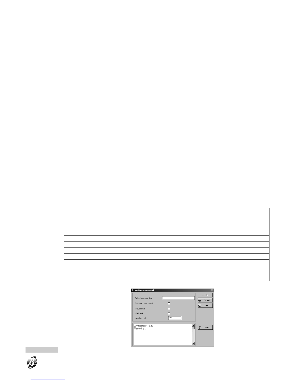
Remote Downloading from computer
The Panel can be programmed through the B-MODor B-MOD/RX modem.
+
The Teleservice option must be enabled by the User (refer to Enable/Disable Teleservice section in the USER
MANUAL).
Step 1 Connect the modem to the computer serial port by means of the serial cable.
Step 2 Select Serial ports from the Options menu----then select the serial port----used for the modem connection to the
Panel----f rom the Remote section. Click OK to confirm.
Step 3 Setup the Modem (refer to the Modem section in the Security Suite manual).
Step 4 Select Connecting from the Modem menu to open the Connection management window (see Figure 38).
Step 5 Program the Connection management window as follows.
----Enter the Panel telephone number in the Telephone Number section.
----Program Disable Tone Check option (refer to Telephone section)
----Program Double Call and Callback options (refer to Teleservice section) as per requirements.
----Ent er the In sta lle r Code PIN
+
The parameters in the Connection management window can be temporarily changed without affecting the programmed parameters of the open customer.
Step 6 Select Dial to start the connection.
The connection status will be shown in the box at the bottom of the Connection management window.
Step 7 Select OK when the following message appears:
OMNIA ACK
Installer code recognized
The Connection management window will close.
Step 8 Use the Download option from the Programming menu to download specific Page data or All programming data
to the Panel.
Full Remote download will take approximately 7 minutes.
Use the Upload option from the Programming menu to upload and view specific Page data or All programming
data from the Panel.
Step 9 Select On-hook from the Modem menu to end the connection.
Software
messages
The connection status will be shown in the box at the bottom of the Connection management page. The following
table shows the messages and meanings.
Omnia/Norma MODEM v. x.xx This is the modem release connected to the computer serial port.
Modem not recognized The modem is not recognized on the selected serial port. Check the cable and
the selected serial port (see Serial ports----Options menu).
Receiving.... The Modem/Computer system is waiting for an incoming call. This will be the
system status when the page opens.
RING Rings detected on the telephone line.
BACK RING This confirms that the dialled telephone is ringing.
NORMA ACK NormaCom Panel acknowledged.
OMNIA ACK Omnia Panel acknowledged.
Installer Code reading error The Panel cannot read the PIN----probably due to the poor quality signal on the
telephone line.
Failed Connection It is impossible to communicate with the Panel----probably due to the poor quality
signal on the telephone line.
Refer to the Programming from on-site computer section for the downloading instructions.
Figure 38 Incoming Call to Panel
PROGRAMMING 63
Page 64
Programming from Keypad
The parameters in this section can be programmed via keypad, by means of the following options from the INSTALLER MENU.
Tel.Numb.Progr. (Telephone Number Programming)
Descript.Progr. (Description Programming)
Installer code
User codes
Parameter progr. (Parameter Programming)
Digital-key coding and Voice-message recording can be done via keypad only. These functions can be accessed from the INSTALLER MENU through:
Voice functions
Keys
Reset default
To reset the factory default programming:
disconnect the Main unit power supply (both mains power and battery)
remove the jumper 7 (MEM)
wait for at least 20 seconds
replace the jumper 7 (MEM)
connect the Main unit power supply (refer to Connecting the Power supply).
ATTENTION Jumper 7 MEM must be disconnected for at least 20 seconds in order to ensure full reset of
the factory default programming, and to avoid problems that may occur when the power supply is reconnected to
the Main unit.
Installer code
locked
If the Lock Installer code option is programmed, the Installer PIN will not be reset to factory default (refer to Lock
Installer code in the Options section).
Defaults
The Install-and-go factory default programming allows trouble free installation.
Configuration On first startup the Panel will perform an auto-configuration cycle. The configuration of the BPI Bus peripherals,
stored during this cycle, will become the recognized configuration.
Zones Zones are programmed as: Alarm, Double balanced, single Pulse, Repetitive.
Zones no. 1 and no. 2 are programmed as Entry delay and Exit delay; all other zones are Instant.
All zones are assigned to Partition no. 1.
Outs All outputs are Bistable, with the exception of the first two, that are Monostable with a 3-minute On time. The two
Monostable outputs can be used as bell alarm outputs. The default Off Time is 6 seconds.
Partitions Partitions have:
----30 seconds Entry time
----30 seconds Exit time
----6 seconds Last exit time.
Partition dependency is not defined.
Keypads and
Readers
All keypads are enabled on all the partitions.
All readers are enabled on all partitions. Type A and B arming are not defined (all partitions are disarmed).
Codes Code no. 1 (Code 001) is the only Available-Active User code with factory default programming. Code no. 1
is enabled on all partitions and for all functions. Code no. 1 PIN is 0001.
The Installer code PIN is 0032.
Event-Actions The following events are addressed to output no. 1:
Generic alarm on partition no.
The following events are addressed to output no. 2:
Tamper alarm on partition no.
Tamper on Main unit
Balanced tamper
Tamper on BPI Peripherals
64 Expandable Multifunction Control Panel Omnia
Page 65

False key at reader
The following event is addressed to output no. 3:
Warning generic
The following event is addressed to output no. 4:
Trouble on BPI
Dialler Action no. 1 sends message no. 1 to the first 16 numbers of the telephone-number list, this action will be gener-
ated by the following events:
Generic alarm on partition no.
Action no. 2 sends message no. 2 to the first 16 numbers of the telephone-number list, this action will be gener-
ated by the following events:
Tamper alarm on partition no.
Tamper on Main unit
Balanced tamper
Tamper on BPI Peripherals
False key at reader
A basic system
The Install-and-go factory defaults allow fast and simple installation. A basic system can control all the programmed zones, and will signal alarm status on the connected alarm signalling devices (sirens and telephone diallers etc.). Arming and disarming can be done via keypad or reader.
Connections
Follow the connection instructions carefully.
Zones A basic system has 8 zones. If input expanders are connected to the Bus----the address coding must be done as
per the instructions in the Connecting BPI Peripherals section.
Zones on the Main unit and on the Input expanders must be connected to the sensors as per the double balancing
circuit schematic in the INSTALLATION section.
Please remember that Zones no. 1 and no. 2 are already programmed as Entry delay and Exit delay, therefore,
do not require programming.
Siren Connect the self-powered siren to Output no. 1----use terminal [+N1] and the ground terminal.
Keypads Connect the keypad to the Bus. If more than one keypad is connected----peripheral address coding must be done
as per the instructions in the Connecting BPI Peripherals section.
Readers Connect the readers. to the Bus. If more than one reader is connected----peripheral address coding must be done
as per the instructions in the Connecting BPI Peripherals section.
Telephone dialler Install OmniaVOX as per the instructions in the OmniaVOX section.
Telephone line Connect the telephone line as per the instructions in the INSTALLATION section.
Programming
Telephone
numbers
Program the telephone numbers----to be called by the Di aller in the event of alarm or tamper----as per the instructions in
the Telephone numbers section in the KEYPAD OPERATIONS section. The first 16 numbers are available.
Voice messages Voice mess. 001 should be used for the alarm status message.
Voice mess. 002 should be used for the tamper status message (maximum 15 seconds per message).
Record as per the relevant instructions in the Voice functions section in the KEYPAD OPERATIONS section.
Codes By default User code no. 1 is Active----PIN 0001. To change the PIN of User code no. 1----refer to Code Pro-
gramming in the USER MANUAL.
Program the necessary codes as per the instructions in the User codes section in the PROGRAMMING FROM
KEYPAD manual.
Keys Program the keys as per the instructions in the Keys section in the PROGRAMMING FROM KEYPAD manual.
Using the System
Arming and
disarming with
code
To arm the system: enter the User code then press the key.
To disarm the system: press the key then enter the User code.
Arming and
disarming with key
The system can also be armed/disarmed by valid keys.
To arm the system: use a valid key/card at any reader and press the key button once. The red LED will go ON.
PRG
ON
RES
OFF
PROGRAMMING 65
Page 66
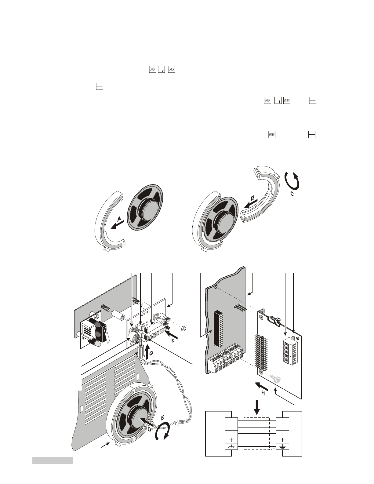
The system will arm when the key/card is removed. The red LED on the reader will remain ON.
To disarm the system: use a valid key/card at any reader. The red LED will go OFF. The system will disarm
when the key/card is removed. The red LED will remain OFF.
Stop alarm on
siren
To stop siren signalling generated by an alarm zone event:
----use a valid key/card at any reader or disarm the Panel as per above.
To stop siren signalling generated by zone tamper or Alarm on panel:
----sel ect S top alar m fr om t he USER MENU.
----enter the User code, press , , .
Stop alarm status will be signalled by a flashing message on the keypad.
Press to exit the Stop alarm status.
Telephone dialler
stop
To stop the telephone dialler----en te r the User code at any keypad then press , , . Press to exit the
USER MENU.
The telephone dialler can be stopped automatically as per the instructions in the Stop alarm with key section in
the FACILITIES section.
Reset Alarm
memory
To delete the alarm memory----enter the User code at any keypad, then press twice. Press to exit the
USER MENU.
0
EXC
ESC
9
EXC
ESC
EXC
ESC
SP– SP–
Microphone
board
Voice board
SP+ SP+
MIC MIC
100
102
91 92 94 95 96 97
98
99
I
101
89 90 93
Figure 39 Parts identification and installation of the OmniaVOX kit
Page 67
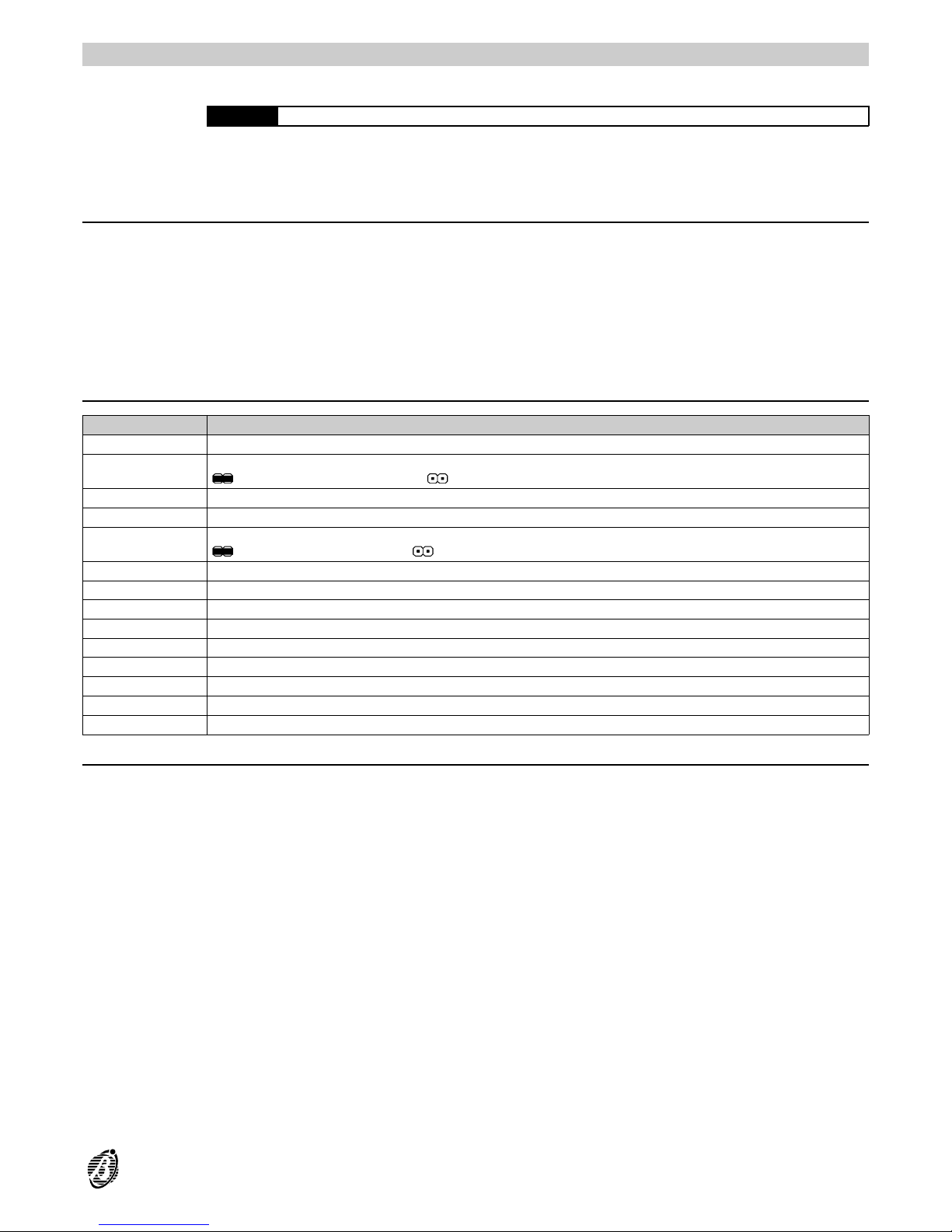
OmniaVOX
WARNING Disconnect the Mains and battery power before installing the OmniaVOX board.
OmniaVOX greatly increases the resources of the Omnia system. The OmniaVOX kit comprises a Voice board,
Microphone board and Speaker. The recorded voice messages can be assigned to the telephone dialler num-
bers, or to the Omnia inputs (for input status control via telephone). They can also be used as answer messages
(answering-machine feature).
Features
Messages recorded on electronic memory (ChipCorder technology™)
Records 14 Voice messages: 2 of 15 seconds; 2 of 10 seconds and 10 of 4 seconds
Speaker
Telephone-dialler
Answering-machine
DTMF management for Omnia-status control via telephone
Listen-in and remote 2way Speaker system (Teleassistance)
Parts identification
PARTS DESCRIPTION
89 Remote Microphone Connector
90
Jumper to enable the Remote Microphone (optional), to be connected to connector 89:
> Remote Microphone enabled; >Remote Microphone disabled
91 Voice board terminals
92 Voice board
93
Jumper to enable the Local Microphone (102):
> Local Microphone enabled; > Local Microphone disabled
94 Main unit Voice board connector
95 Main unit Main board
96 Terminal board (for Microphone board connection)
97 Voice board activity LED
98 Voice board
99 Speaker
100 Speaker plug
101 Connector for the Speaker plug
102 Microphone
Installation
Install the OmniaVOX as follows (see Figure 39).
Step 1 Fit the Speaker into one part of the plastic holder (see A in Figure 39) then join the two parts (see B in Figure 39)----
twist to lock in place (see C in Figure 39).
Step 2 Fit the Speaker onto the backplate (see D in Figure 39)----turn clockwise (see E in Figure 39).
Step 3 Fit the microphone board into place (see F in Figure 39).
Step 4 Plug the Speaker into the connector 86 (see G in Figure 39).
Step 5 Connect the Voice board 94 to the Main Unit board (see H in Figure 39).
Step 6 Use shielded cable to connect the Microphone to the Voice board (see I in Figure 39).
+
Delete the Voice board memory----refer to the Voice features section for instructions.
OmniaVOX 67
Page 68

Expand Listen-in partitions
Listen-in coverage can be expanded by connecting several Microphone-Speaker boards to the Voice board. This
is especially useful for large premises, or in places where there is risk of sound muffling caused by walls or machinery, etc.
The Microphone and Speaker boards can be housed in custom made accessory boxes (MINI-BOX). The MINI-
BOX can be either wall mounted, or flush mounted to 503 outlet boxes or similar.
The leaflet in the MINI-BOX package provides the Microphone and Speaker board installation instructions.
+
The Microphone and Speaker board placements should be tested for squealing, before mounting.
+
The Microphone board and Speaker board must be housed in separate boxes, otherwise squealing may occur.
The supplementary boards must be connected in parallel to the Voice board, as per Figure 40. The number of
supplementary boards, and the connection lengths can affect sound quality, therefore:
----do not connect more than 4 Microphone-Speakers to the Voice board.
----do not use more than 50 metres of cable between each Microphone-Speaker board and the Voice board.
+
When recording messages----use the Microphone board that is nearest to the Voice board, and temporarily disconnect the other boards.
All Microphone-Speaker boards will be interconnected during Teleassistance mode----a llo wing several users to
communicate.
Manual selection
Installation of several Microphone-Speaker boards will allow the user to listen-in on the various parts of the premises simultaneously, however, sound tracing will not be possible.
For sound tracing----complete the connections, as per Figure 41. The schematic shows the Voice board and 4 Microphone-Speaker boards, and also:
a 4-Output expander----Omnia/4OUT
a 4-Input expander----Omnia/4IN
two Relay modules----Omnia/4R
Omnia must be programmed as follows.
All the outputs of the Output expander must be Reserved, Bistable and Normally Open.
The Input expander zones must be:
----Instant; Repetitive; Normally Open.
The zones must be either assigned to a *reserved partition, or programmed as Test, and must have an Alarm
status Voice message that will act as placement identifier.
Enable Remote
listen-in via
telephone
Step 1 Press 5 (on the telephone keypad)
Step 2 Enter the number of the output that will activate the required Microphone-Speaker Board----two digits are required,
therefore, enter 0 before output numbers 1 through 9.
Step 3 Press 1 to start Remote listen-in.
Example
If the Output-expander address is no. 01, as per Figure 41, its hardware outputs----OC1, OC2, OC3 and OC4 will
correspond to software outputs no. 5, no. 6, no. 7 and no. 8.
Therefore, to enable software output no. 5 for remote listen-in on the first VOX-REM placement enter 505 then
press 1.
Step 4 Press # then enter 405 to stop the output and end the Remote listen-in session.
+
Enter 300 (Check input zones option) to trace sounds during a Remote listen-in session on the entire premises.
Auto-select mode
Auto-select mode is extremely useful, as the Panel will select the nearest VOX-REM board to the zone in alarm
status. Figure 41 shows the necessary connections----the outp ut must be programmed accordingly, and some parameters must be added to the Event-Actions page.
The 4 outputs must be: Monostable; Normally open; and Not Reserved. The ON time will be as per the programmed activation time of the Microphone-Speaker Board of the placement in question. Each of the outputs---connected as per Figure 41 will activate one of the VOX-REM boards.
The partition and/or Panel events in the Event-Actions page will activate the alarm devices and telephone dialler.
Therefore, the zone events will be free to control the outputs.
The zone events----assigned to the placement in question must be programmed to activate the output that controls
the relevant VOX-REM board----all 4 out put s must be programmed in the same way.
68 Expandable Multifunction Control Panel Omnia
Page 69
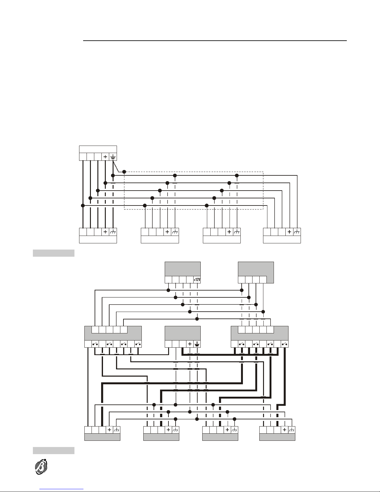
Auto-select mode will allow the user (called by the telephone dialler) to activate Remote listen-in on the specific
placement.
Manual and Auto-select mode
Manual and Auto-select listen-in can be integrated. This will allow the user to select (manually) specific placements during standby status.
4 outputs are required for Manual-select listen-in mode, and 4 outputs for Auto-select listen-in mode.
The outputs must be connected in two’s----one Manual and one Auto, as per Figure 41.
+
To ensure proper functioning of Auto-select mo de----the manually controlled outputs must be in standby status.
Therefore, the outputs must be reset to standby status when manually controlled listen-in sessions end.
S P +S P +
S P +S P + S P +S P + S P +S P + S P +S P +
S P -S P -
S P -S P - S P -S P - S P -S P - S P -S P -
M I CM I C
M I CM I C M I CM I C M I CM I C M I CM I C
Voice board
VOX-REM
VOX-REM VOX-REM VOX-REM
Figure 40 Connecting OmniaVOX-MS boards to the Voice board (the example shows the connection of 4 OmniaVOX-MS )
S P +S P +
S P +S P + S P +S P + S P +S P + S P +S P +
S P -S P -R L 1R L 1 R L 1R L 1
S P -S P - S P -S P - S P -S P - S P -S P -
M I CM I CR L 2R L 2
O C 2O C 2
O C 2O C 2
O C 2O C
2
L 2L 2
O C 4O C 4
O C 4O C 4
O C 4O C 4
L 4L 4
O C 3O C 3
O C 3O C 3
O C 3O C 3
L 3L 3
O C 1O C 1
O C 1O C 1
O C 1O C 1
L 1L 1
R L 2R L 2R L 3R L 3
+ 1 2+ 1 2
+ 1 2+ 1 2
R L 3R L 3R L 2R L 2 R L 2R L 2
M I CM I C M I CM I C M I CM I C M I CM I C
Voice board
OmniaVOX
Output exp. 01
Omnia/4OUT
Input exp. 01
Omnia/4IN
Omnia/4R Omnia/4R
2 VOX-REM
nd
3 VOX-REM
rd
4 VOX-REM
th
2 VOX-REM
ST
Figure 41 Listen-in schematic
OmniaVOX 69
Page 70
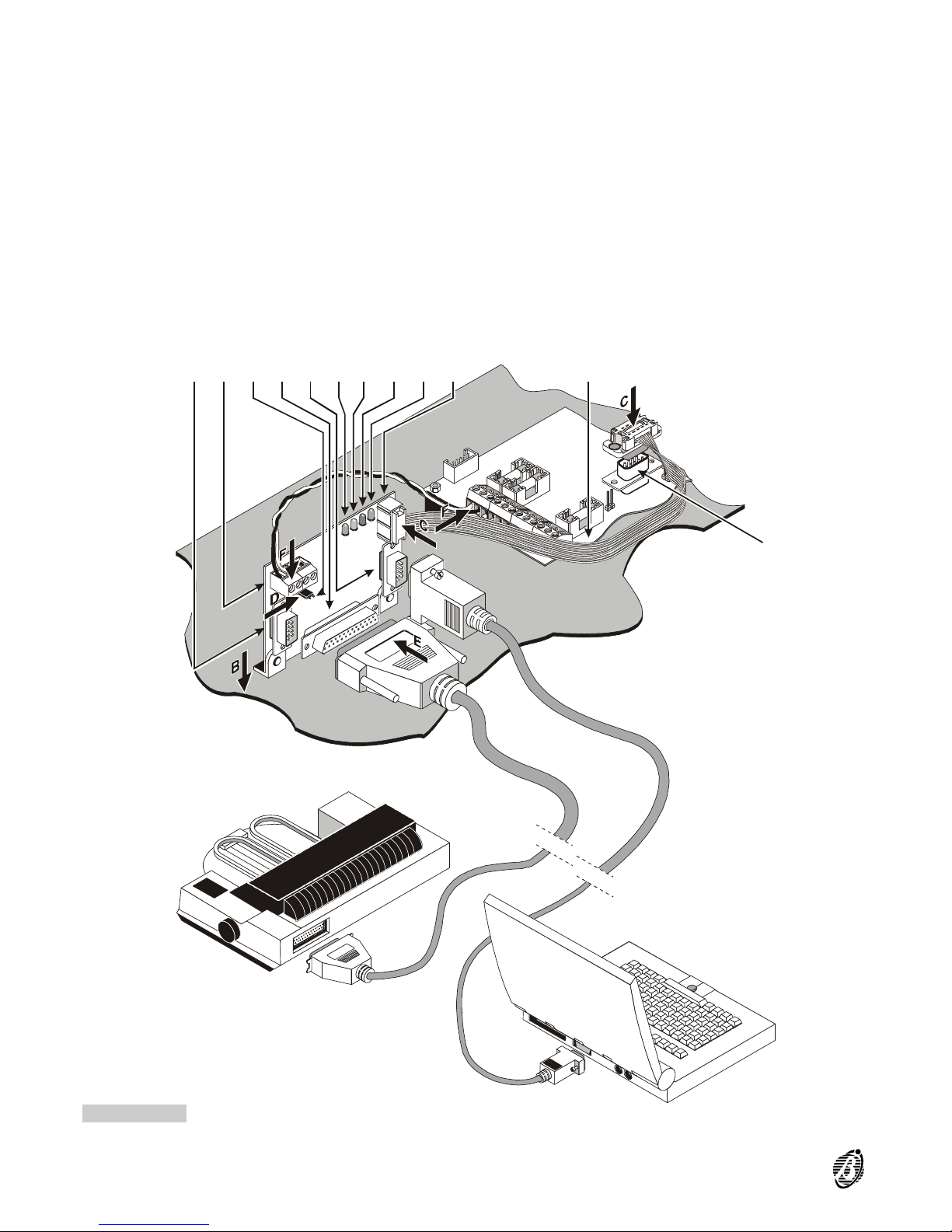
103 104 108 109 110 111 112 113
6
107106105
Figure 42 Parts identification and installation of the OmniaTIMER
70 Expandable Multifunction Control Panel Omnia
Page 71
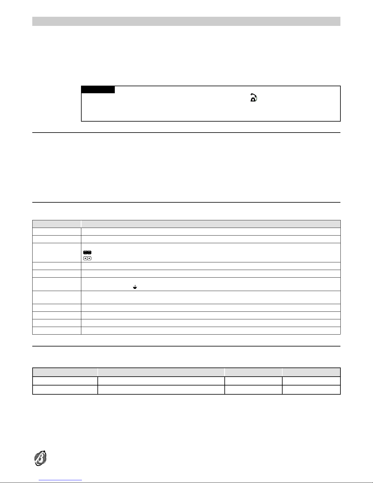
OmniaTIMER
The OmniaTIMER board must be connected to the Main unit serial port----which is duplicated on the interface.
The OmniaTIMER interface allows direct connection to a serial or parallel printer----for real-time printout of events,
and entire Event buffer printout.
The on-board Scheduler can control automatic Arming/Disarming of the 8 partitions, and the ON/OFF times of the
8 Timers (for appliance control).
+
The OmniaTIMER cannot be programmed via keypad.
ATTENTION The OmniaTIMER has a maximum error margin of 30 seconds.
When Omnia engages the telephone line (indicated by T above the icon on the keypad)----the Omnia-
TIMER will delay the scheduled operations until Omnia hangs up.
Scheduled operations will be ignored during the Omnia programming session----o r when Omnia is connected to
a computer via serial port.
General features
Serial printer or parallel printer connection
Real-time printout of events, and entire Event buffer printout----requested via keypad
2 arm and 2 disarm operations per day for each partition
8 Timers to control up to 8 appliances (ON/OFF)
Flexible time and day programming (Weekday, Bank holiday, etc.)
Overtime Requests
Automatic switch over from Summer Time to Standard Time and vice versa
Parts identification
The numbers in boldface in the description table refer to the parts shown in Figure 42. The LED and connector
identifier letters are silk screened on the board (see Abbreviations in square brackets).
PARTS DESCRIPTION
[SPT] 103 Serial printer port
104 Terminal Board
[PRN] 105
Jumper to select:
> parallel printer port (default)
> serial printer port
[PPT] 106 Parallel printer port
[PC] 107 "New" serial port for computer connection
[ON] 108
Green LED normally ON----LED OFF signals that the OmniaTIMER is not powered. Check for voltage across
terminals [+12V] and [ ].
[CTS] 109
Yellow LED normally OFF----LED ON signals that the Main unit is busy, therefore, the OmniaTIMER cannot
perform the programmed operations.
[ER.PRN] 110 Red LED normally OFF----LED ON signals printer fault. Check that the printer is connected properly and on line.
[SER] 111 Yellow LED normally ON----LED OFF signals that the OmniaTIMER is using the Main unit serial port.
[OMNIA] 112 Main unit serial port connector
113 Flat cable for OmniaTIMER connection to Main unit
Installation
Printer The following table shows the main differences between serial and parallel printers----c ost, connection length (be-
tween printer and interface), and printing speed.
PRINTER MAX. CONNECTION LENGTH SPEED COST
Parallel 10 meters High High
Serial 40 meters Low Low
Parallel printers are preferable as they are faster, however, the maximum connection length of 10 meters greatly
reduces layout flexibility.
OmniaTIMER 71
Page 72
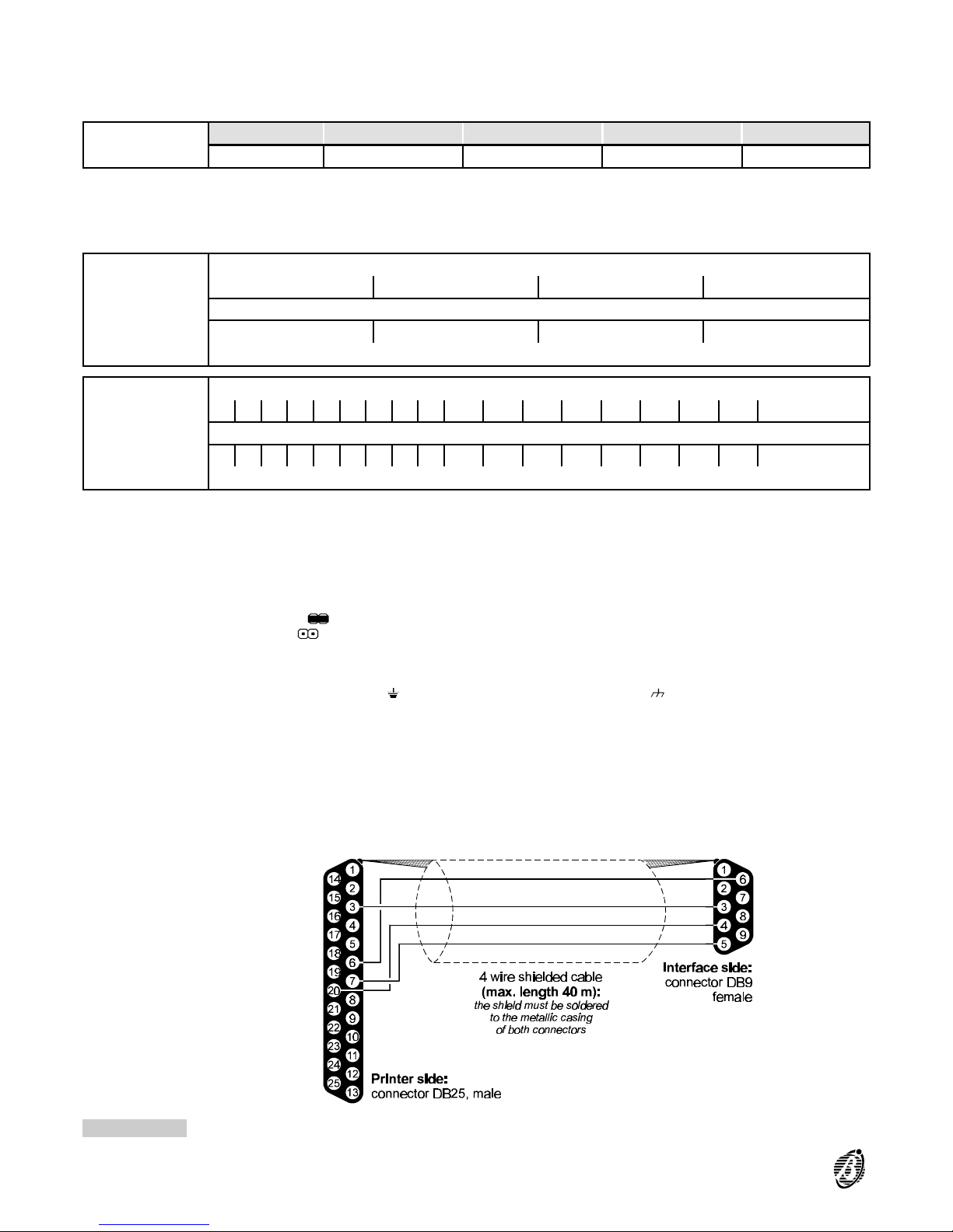
Serial printers are slower, therefore, they block the Scheduler for longer. However, the maximum connection
length of 40 meters allows greater layout flexibility.
+
The Main unit must not be on view for security reasons.
Serial printers must be connected as follows.
Serial printer
Setting
BAUD RATE PARITY DATA BITS STOP BITS PROTOCOL
1.200 E (even) 8 1 DTR/DSR
Printer
Connection
Use the moulded plug lead (usually supplied with the printer).
+
Leads with moulded plugs cannot be chased, however, plug free cables can be chased and connected, as per below.
Connection cable
for serial printer
to interface
Interface side: connector DB9----fem ale
3456
4 wire cable + shield:
the shield must be soldered to the metallic casing of both connectors
2207 6
Printer side: DB25 male connector
Connection cable
for parallel
printer to inter-
face
Interface side: DB25 male connector
123456789 10 11 12 13 14 15 16 17 19
18 wire cable + shield:
the shield must be soldered to the metallic casing of both connectors
123456789 10 11 12 13 14 32 31 36 1517/1930
Printer side: Centronics 36 pin male connector
Installation
Instructions
1. Lay the cable.
2. Fit the OmniaTIMER to the rear plate of the Main unit----as per Figure 42.
3. Using the flat cable (113), connect the OmniaTIMER to the Main unit (connector 112 to connector 6).
4. Using the jumper (105), select the printer type:
Parallel printer >
Serial printer >
5. Plug the parallel printer into the parallel printer connector (106)----or the serial printer into the serial printer connector
(103) of the OmniaTIMER.
6.
Connect terminals [+12V] and [ ] of the OmniaTIMER to terminals [+B] and ] of the Main unit.
Figure 43 Connecting the serial printer to the interface
72 Expandable Multifunction Control Panel Omnia
Page 73
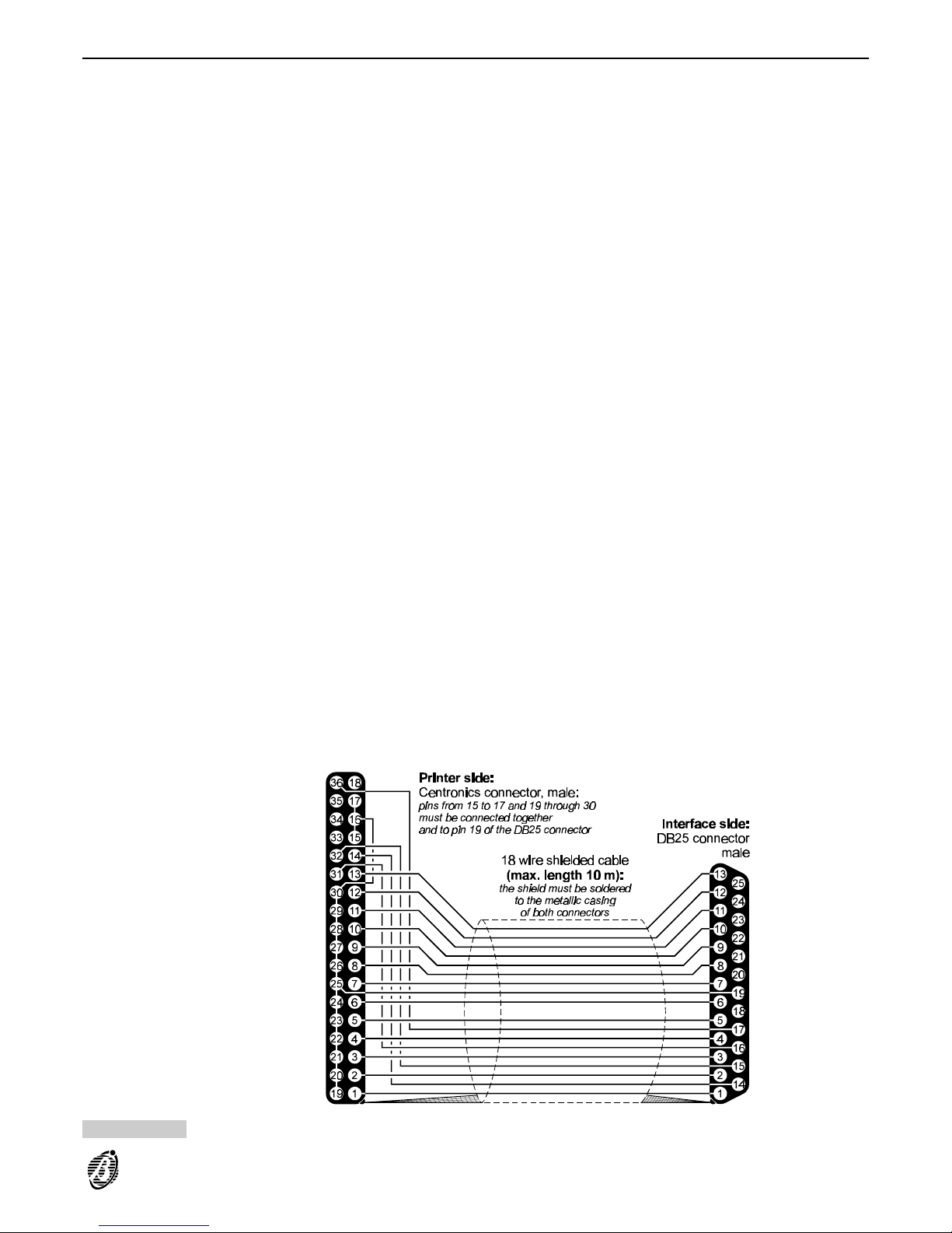
Programming
The Scheduler (see Figure 45) can be programmed to control automatic Arming/Disarming of the 8 partitions (2
arm and 2 disarm operations per partition), and the ON/OFF times of the 8 Timers that can control up to 8 appliances (Courtesy lights, Sprinkler system, Heating, etc.). The programmed Scheduler parameters can be downloaded to the Panel via on-site serial connection or telephone line.
Scheduler
programming
1. Select the Scheduler option from the PROGRAMMING menu.
2. Select Type Descr.
3. Define the day Types in the Type Descr. window (Weekday, Bank holiday, etc.) then click OK to confirm and exit.
The customized day Types will be shown on the Type tags (at the bottom of the Partitions table).
4. Select the required day Type (the Partitions window will change accordingly). Use the < and > arrows to scroll the
row.
5. Program the Disarm/Arm times for partitions 1 through 8.
Time format: hh (hour)----mm (minutes:
----required time 7:45 a.m. = 07.45
----required time 5:45 p.m. = 17.45
Errors will be signalled by an error message.
6. Select Timers to step from the Partitions window to the Timers window then program the ON /OFF times of the
appliances controlled by the Timers (Courtesy lights, Sprinkler system, Heating, etc.).
7. Step back to the Partitions window.
Models The details of each day Type form its Model----and must be entered in the Models table (as follows).
+
To enter the Day, Month, Year, Weekday, Type or * (irrelevant) in the corresponding field----c lic k the field and select from the list that appears on the right of the Models table.
no. This reference number cannot be changed----use the up/down arrows to scroll the number list.
Day Enter Day number----1 th rough 31 or the asterisk (*).
----Select the asterisk (*) if the Day number is irrelevant for the Model.
----If a n invalid Day number is selected----it will be rectified to the highest Day number for the month in question.
Month Enter the Month.
----Select the asterisk (*) if the Month is irrelevant for the Model.
Year Enter the Year (up to 2014).
----Sel ect t he a ster isk ( *) if the Year is irrelevant for the Model.
Interval Intervals (Summer holidays or Bank holidays) require two rows.
Enter the Day numbers (e.g. 1st January through 4th January), or Weekdays (e.g. Monday through Wednesday).
Figure 44 Connecting a parallel printer to the interface
OmniaTIMER 73
Page 74
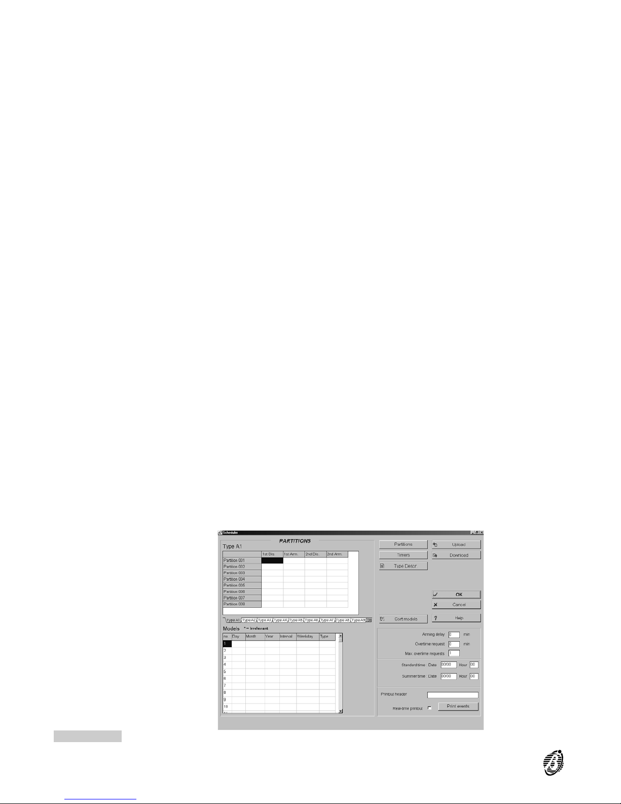
Weekday Enter the Weekday Model (Monday, Tuesday, etc.), or Weekday Interval.
Step 1 Enter an asterisk (*) in the Day----Month----Year fields.
Step 2 Enter the weekday (Monday, Tuesday, etc.) under Weekday.
----If a W eekday is selected the Day, Month, and Year cannot be selected.
Type Enter the day Type (select from the customized list).
Sort Models Click Sort Models to put the Models into order----as per priority (refer to Model Priority).
Autoarming
warning
Enter a value (in minutes) to establish the time lapse between the Autoarming warning signal, and partition arming.
Example
If partition no. 1 is programmed to arm at 17:45 with a 15 minute delay----event no. 360 will be generated at
17.30----Arming delay partition 1 [Partition 001].
The event will end when the partition arms----after the programmed Arming delay, or after an overtime request.
Accepted values: 0 through 240 minu tes ----steps of 1 minute:
----values over 240 will be rectified to 240 when OK or SEND is selected;
----0 corresponds to no Autoarming warning.
Overtime
request
Enabled users can make Overtime requests through the USER MENU.
----If a Time r controlled partition is programmed to arm at 17:45, and a 60 minute overtime request is made at
17.30----the partition will arm at 18:45 (i.e. if no other overtime requests are made beforehand).
Accepted values: 0 through 60 minutes----steps of 1 minute:
----values over 60 will be rectified to 60 when OK or SEND is selected;
----0 will be ignored.
Max. overtime
requests
Specify the maximum number of overtime requests. Any requests made after the programmed number will be ignored.
Accepted values: 0 through 180 min ute s ----steps of 1 minute:
----requests for over 180 minutes will be rectified to 180
----0
will be rectified to 1
+
Overtime requests affect the imminent arming time only.
Standard time Enter the Summer time to Standard time change-over Date----the Main unit clock will go forward 1 hour.
Accepted format: dd (day) 00 through 31----mm (month) 00 through 12:
----00 i n the day or mo nth field will disable this feature.
----it will be impossible to exit the page by means of OK----or SEND (Main unit programming session) if wrong values are entered.
Enter the change-over Time.
Accepted format: hh (hour) 00 through 23:
----values over 23 will be rectified to 23 when OK or SEND is selected;
----00 in the hour field will disable this feature.
Summer time This is the Date and the Time of change-over from Standard to Summer time.
Printout
header
Enter the Event buffer printout header (maximum 16 characters).
Figure 45 OmniaTIMER programming page
74 Expandable Multifunction Control Panel Omnia
Page 75
Real-time printout Select this option for real-time events printout----o n the printer connected to the printer interface. Select the Print
buffer option from the USER menu for a entire Event buffer printout (the last 200 events).
WARNING The OmniaTIMER will be disabled during the entire Event buffer printout----whi ch can take several
minutes. Therefore, the programmed arm/disarm times will be delayed accordingly.
Print events This option allows the user to select printout of specific events only, thus disabling the Scheduler for less time.
Operations
The Scheduler (see Figure 45) can be programmed to control automatic Arming/Disarming of the 8 partitions (2
arm and disarm operations per partition), and the ON/OFF times of the 8 Timers that can control up to 8 appliances (Courtesy lights, Sprinkler system, Heating, etc.). The programmed Scheduler parameters can be downloaded to the Panel via on-site serial connection or telephone line.
The days can be programmed individually. 16 Day Models can be programmed for the Partitions, and 16 for the
Timers.
+
To enter the Day, Month, Year, Weekday, Type or * (irrelevant)----click the corresponding box and select from the
list that appears on the right of the Models table.
Weekdays The Day number----Month----Year are irrelevant for the Weekdays Model (Monday through Friday). This Model is
an Interval, therefore, requires two rows.
Step 1 Enter an asterisk (*) in the Day----Month----Year fields (upper row.).
Step 2 Enter Monday in the Weekday field on the upper row and Friday in the field directly below.
Step 3 Click the upper----then the lower field in the Interval column----the words Start and Stop will be shown, as per the
example.
no. Day Month Year Interval Weekday Type
9 * * * Start Monday Weekdays
10 * * * Stop Friday *
Saturdays This Model is for Saturdays.
Step 1 Enter an asterisk (*) in the Day----Month----Year , as per the example.
Step 2 Enter Saturday in the Weekday field.
no. Day Month Year Interval Weekday Type
8 * * * * Saturday Saturdays
Summer Holidays Summer holidays must be programmed, otherwise, the Scheduler will apply the times programmed for the Week-
day, Saturday and Holiday Models (unless disabled).
The Summer holidays Model is an Interval, therefore, requires two rows. The example shows Summer holidays
from 1st August to 15th August.
Step 1 Enter 1 in the Day field of the upper row and 15 in the lower.
Step 2 Enter August in the Month field of upper and lower rows.
Step 3 Click the upper----then the lower field in the Interval column----the words Start and Stop will be shown, as per the
example.
no. Day Month Year Interval Weekday Type
1 1 August * Start * Summer Holidays
2 15 August * Stop * *
OmniaTIMER 75
Page 76
Christmas
Holidays
Christmas holidays must be programmed as per Summer Holidays. However, if the holiday continues into the New
year----it must be programmed as per the example below (Start Day 24th December 2001---- Stop Day 6th January
2002). In this case the Year field must be updated annually.
no. Day Month Year Interval Weekday Type
no 24 December 2001 Start * Xmas Holidays
n
o
+1 6 January 2002 Stop * *
If the Christmas holiday is divided into two Intervals, the Year need not be entered, and therefore, need not be updated.
Xmas Holidays 1 > the Days from 24th to 31st of December
Xmas Holidays 2 > the Days from 1st to 6th of January
no. Day Month Year Interval Weekday Type
3 24 December * Start * Xmas Holidays 1
4 31 December * Stop * *
5 1 January * Start * Xmas Holidays 2
6 6 January * Stop * *
Bank Holidays: e.g. 1st May, program as per the example.
no. Day Month Year Interval Weekday Type
7 1 May * * * 1st May
Model Priority Days may belong to more than one Model, therefore, the programmed times of the less frequent Model will be ap-
plied. For example Bank Holiday Model----1st May is applied once a year, therefore, will have priority over the
Weekday Model, which is applied 5 times per week.
Timers
The 8 Timers can be programmed to control the ON/OFF status of up to 8 appliances (Courtesy lights, Sprinkler
system, Heating, etc.).
Connecting the Computer
Connect the OmniaTimer to the computer (via connector 107). In this way, the computer and OmniaTIMER will
share the Main Unit serial port----with the fol lo wing implica tions.
The computer connection will have priority over OmniaTIMER connection. When the computer connects to the se-
rial port, the OmniaTIMER will be disabled automatically, and therefore, will be unable to perform the programmed
operations. The OmniaTIMER will be reinitialised when the computer connection ends. Operations requested during disabled status of the OmniaTIMER will be ignored.
When Omnia connects to the serial port (CTS LED ON), the OmniaTIMER will be disabled automatically. There-
fore, all scheduled operations (arm/disarm partition----e nable/disable Timer----printout or entire Event buffer printout) will be delayed until the serial port is free again.
76 Expandable Multifunction Control Panel Omnia
Page 77
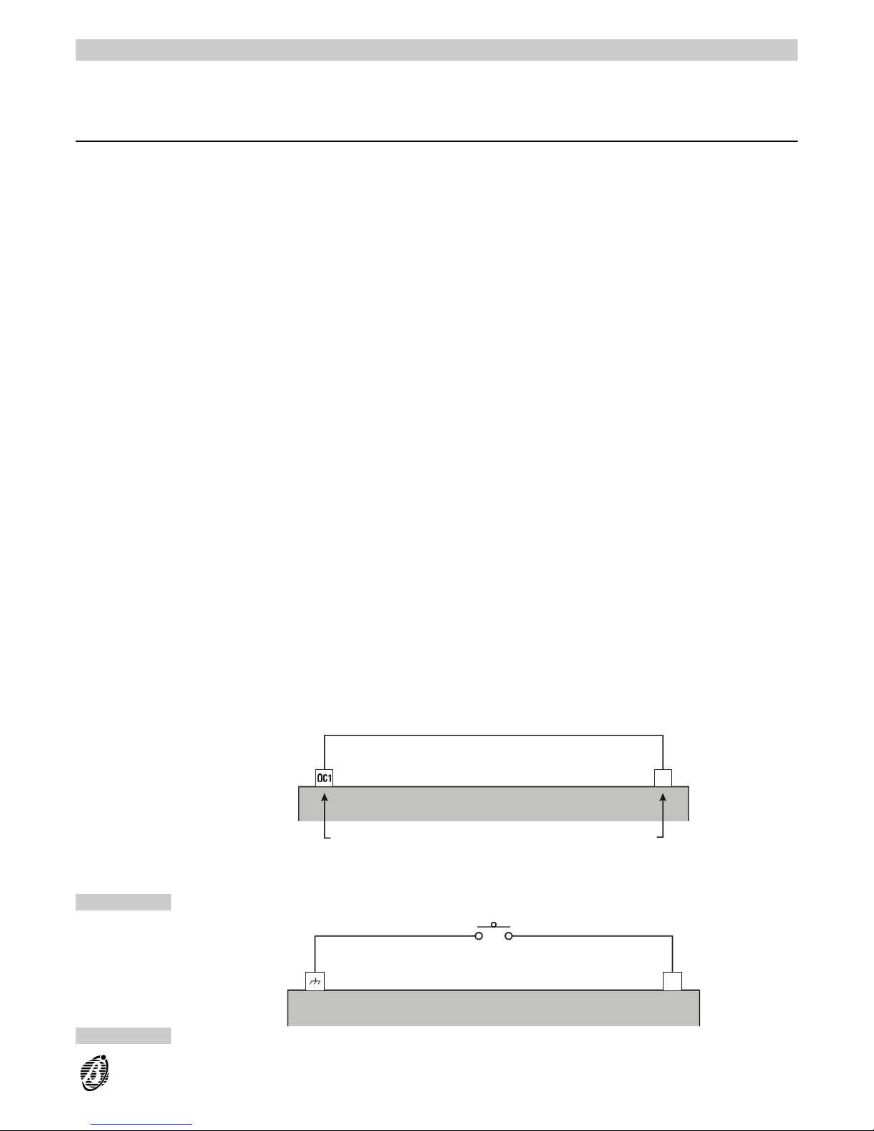
FACILITIES
This section describes some of the most frequently used Omnia/S system facilities.
Fast arming
The connections and programming described in this section will allow users to arm specific partitions (areas), by
simply pressing a keypad button. The Fast arming facility can be associated with a Super key event (Events no.
390 [Super key 001] through no. 399 [Super key 000]).
The selected Super key event must be programmed----i n th e {E vent -Actions} page----to activate an output that is
connected to a zone that can arm the specific areas.
Following is a programming example, utilizing:
Event no. 391: Super key 1 [Super key 001];
Output no. 3: corresponds to terminal [OC1] on the Main unit;
Zone no. 8: corresponds to terminal [L8] on the Main unit.
+
The connections are as per Figure 46.
Event-Actions Programming for Event no. 391[Super key 001]:
Outputs ON:
33.
Outputs Programming for Output no. 3:
Type: Monostable
Attribute: Normally open
Time: On time----1 Sec.
Zones Programming for Zone no. 8:
Command
+
Command: Arm only
Balancing: Normally open
Sensitivity: Standard Pulses 1
Cycles: Repetitive
Partition: this value determines the partitions that will arm when key 1 (on any keypad) is pressed for more than 3
seconds.
As a result of the described connections and programming, the selected partitions (areas) will arm when the programmed button is pressed for 3 seconds.
+
Super key status will be signalled by a beep.
As the zone is programmed for arming only, the fast arming request will be ignored when the partitions are already
armed.
The output action, activated by the Super-Key event, can also be activated by a key connected to the command
zone, as per Figure 47.
L 8L 8
Mani unit
Output no. 3:
Monostable
Normally open
On time - 1 Sec.
Zone no. 8:
Command
Only arm
Normally open
Sensitivity - Standard
Pulses - 1
Figure 46 Fast arming by Super key
L 8L 8
Main unit
Figure 47 Fast arming by button
FACILITIES 77
Page 78
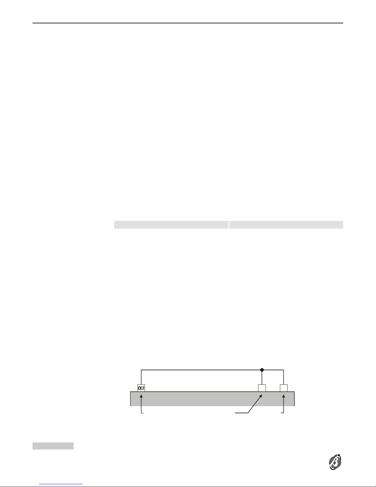
Temporary disarming (patrol)
The connections and programming described in this section will allow users to disarm one or more partitions for a
programmed interval. This facility is especially useful in commercial buildings, where security staff require temporary access to specific partitions (areas) for patrol purposes.
Following is a programming example, utilizing:
Event no. 418: Recognized user code 10 [Code 010]
Output no. 4: corresponds to terminal [OC2] of the Main unit
Zones no. 6 and 7: correspond to terminals [L6] and [L7] of the Main unit.
+
The connections are as per Figure 48.
Codes Programming for Pr. 10 Code:
Description: Patrol
Available
Active
Enables user menu: none
Enable instant action: none
Codes programmed in this way will be enabled for the patrol use only.
Event-Actions Programming for event no. 418 ---- Recognized user code 10 [Code 010]:
Output ON: 4
Outputs Programming for Output no. 4:
Type: Monostable
Attribute: Normally open
Time: On time [patrol time + 1]
MinMin.
Zones Programming for Zones no. 6 and 7:
Zone no. 6 Zone no. 7
CommandCommand CommandCommand
Command:
Disarm onlyDisarm only Arm onlyArm only
Balancing:
Normally openNormally open Normally openNormally open
Sensitivity:
Standard - 1 pulseStandard - 1 pulse Low - Pulse lengthLow - Pulse length[Patrol time] Min.Min.
Cycles:
RepetitiveRepetitive RepetitiveRepetitive
Partition:
Select the partitions that will be disarmed for the patrol time----for both zones.
As a result of the described programming and connections, when code no.10 is digited and Enter is pressed, the
programmed partitions will disarm for the programmed time.
To refresh the patrol time:
----all ow th e pr ogr ammed time to elapse;
----wait 60 seconds then enter the patrol code.
+
If a patrol code is entered when the patrol time is running it will be ignored.
L 7L 7L 6L 6
Main unit
Output no. 4:
Monostabe
Normally open
On Time -
- [patrol time + 1] Min.
Zone no. 7:
Command
Only arm
Normally open
Sensitivity - Low
Pulse length -
- [patrol time] Min.
Zone no. 6:
Command
Only disarm
Normally open
Sensitivity - Standard
Pulses - 1
Figure 48 Temporary disarming (patrol)
78 Expandable Multifunction Control Panel Omnia
Page 79
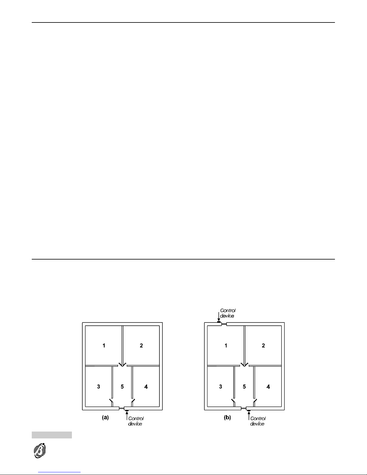
Managing Common Partitions
The connections and programming described in this section will allow the system to manage Common partitions.
This facility is especially useful in commercial buildings where several offices or rooms are adjacent to a common
area, such as corridor.
Following is a programming example, that shows how the Panel will arm and disarm partition 5, in accordance with
the status of partitions 1, 2, 3 and 4.
Figure 49a illustrates access to several partitions (1, 2, 3 and 4), controlled from a device (reader or keypad) at
the entrance of partition 5 (the common partition).
Programming for common management of partition 5:
the control device must be enabled on partitions 1, 2, 3 and 4;
each user key/code/card must be enabled on a specific partition (1, 2, 3 or 4);
partition 5 (the common partition) must be programmed as dependent (Depends on attribute) on partitions 1, 2, 3
and 4.
Thus the users will have access to a specific partition (1, 2, 3 or 4), and also to partition 5.
Partition 5 will arm when all the partitions it depends on arm, and will disarm when one of the partitions it depends on disarms.
The layout in Figure 49b is similar to Figure 49a, however, partition 1 has its own entrance, and control device.
Programming Common management of partition 5:
the control device located in partition 5 must be enabled on partitions 1, 2, 3, 4 and 6 (partition 6 is a "virtual" parti-
tion and is ineffective);
the control device, at the entrance of partition 1 must be enabled on partition 1 only;
the partition 1 user key/code/card must be enabled on partition 1 and partition 6, all other users keys/codes/cards
must be enabled on their specific partitions;
partition 5 must be programmed as dependent on partitions 2, 3, 4 and 6.
+
If all the partitions are armed, and the entrance to partition 1 is used----p artition 5 will not disarm, as it depends on
partition 6 and not on partition 1.
As a result of the described connections and programming, it will be possible to manage several independent partitions, each with their own entrance (up to 8 partitions, including the "virtual partition").
+
The zones that protect control devices (Readers/Keypads) must be programmed as Entry delay and Exit delay
type.
Figure 49 Managing Common Partitions
FACILITIES 79
Page 80
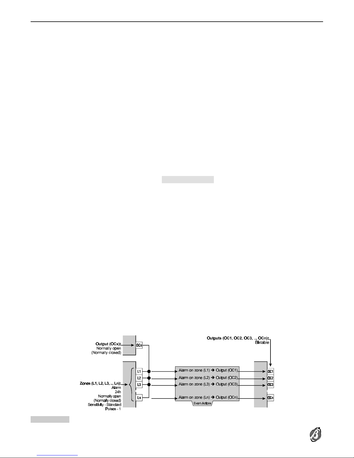
Multi-output events (via Hardware)
The connections and programming described in this section will allow a single event to activate several outputs.
This facility is especially useful in installations where the same output signal is required in several different placements. This is often the case in noisy environments, where horns and strobes are required in order to provide adequate Alarm signalling.
Example In the following example output OCx is assigned to an event that also activates signalling on outputs OC1, OC2,
OC3, ..., OCn.
The connections are as per Figure 50.
+
Output OCx and inputs L1, L2, L3, ..., Ln need to be relatively close for connection purposes.
Zones Programming for the zones that correspond to terminals [L1], [L2], [L3], ..., [Ln]:
Alarm
Type: 24h
Balancing compatible with the attribute of output OCx:
- Normally open if the output OCx is normally open
- Normally closed if the output OCx is normally closed
Partition: all zones assigned to a partition that is not used by keys, codes or to control operations----this partition can
be considered a Technical partition.
Outputs Programming for the outputs that correspond to terminals [OC1], [OC2], [OC3], ..., [OCn]:
Type: Bistable
+
In all cases, the output that corresponds to terminal [OCx] can be programmed as per requirements.
Event-Actions Programming for the Zone alarm events relative to terminals [L1], [L2], [L3], ..., [Ln:
Outputs ON
Alarm on zone (L1):
Output (OC1)Output (OC1)
Alarm on zone (L2):
Output (OC2)Output (OC2)
Alarm on zone (L3):
Output (OC3)Output (OC3)
Alarm on zone (Ln):
Output (OCn)Output (OCn)
As a result of the described connections and programming, activation of output (OCx) will generate the following
events: 24h alarm on panel, Generic alarm on panel and Generic+Tamper alarm on panel. To avoid false
alarms----these events must not be assigned to actions.
The signal on output OCx will also be present on outputs OC1, OC2, OC3, ..., OCn with a 2 second delay (approx.).
+
The signal on output OCx must be present for more than 400 mS in order to activate outputs OC1, OC2, OC3, ...,
OCn.
Figure 50 Multiple output event via Hardware
80 Expandable Multifunction Control Panel Omnia
Page 81
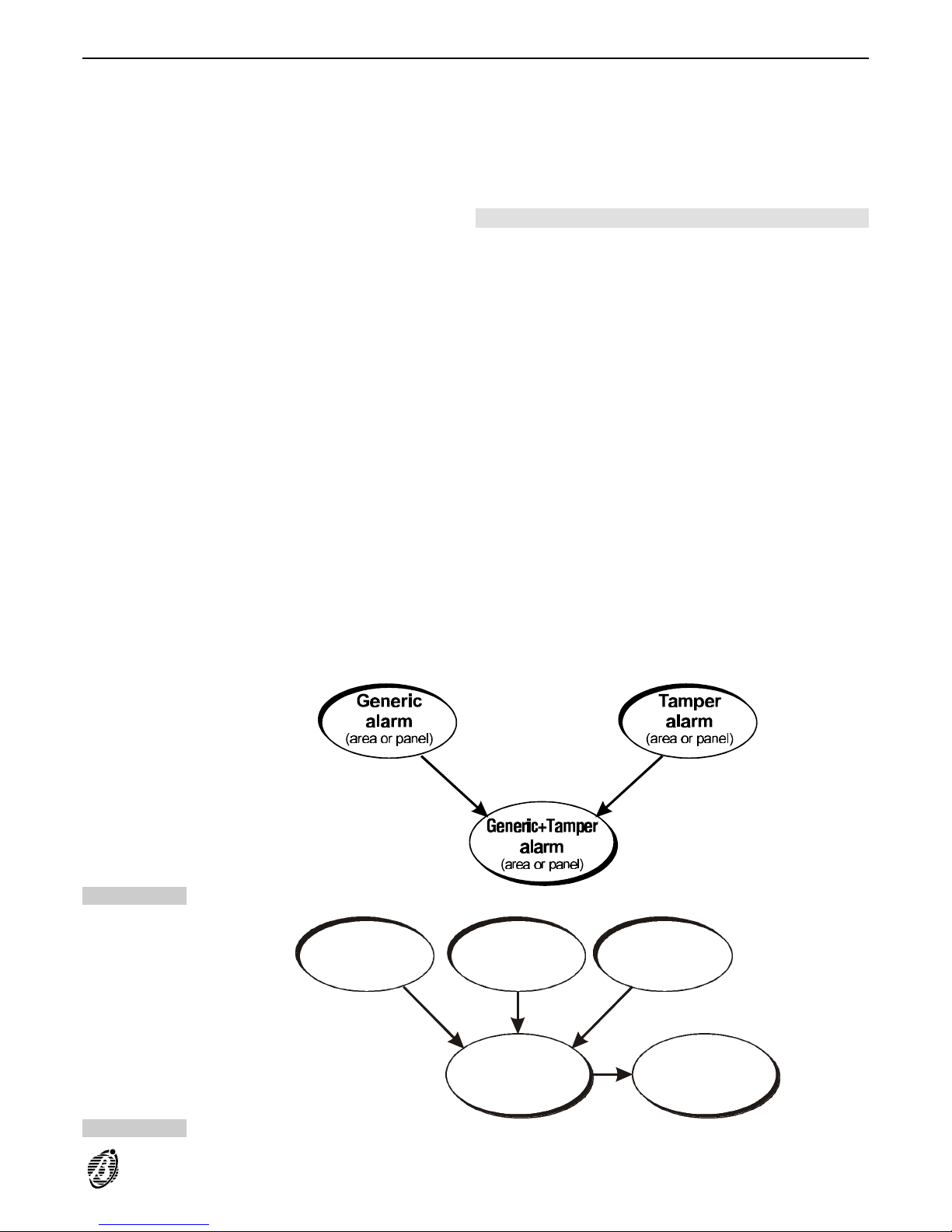
Multi-output events (via Software)
The programming described in this section will allow single events to activate several outputs. This procedure
makes the fullest use of the hierarchy that is inherent in the events structure.
+
The Generic Alarm event (partition or panel) and Tamper alarm event (partition or panel) both trigger the Generic+Tamper alarm event (partition or panel), as the latter is the sum of the previous two events (see Figure 54).
It is possible to assign the Generic+Tamper alarm event (partition or panel) to two outputs (refer to the example).
Event-Actions In the following example, the Generic+Tamper alarm on partition no. event will activate outputs the outputs
identified as x and y.
Outputs ON
Generic+Tamper alarm on partition no.:
Output xOutput x
Generic alarm on partition no.:
Output yOutput y
Tamper alarm on partition no.:
Output yOutput y
The structure illustrated in Figure 52 can also be applied to the activation of several outputs via the same event, if
the zones assigned to a partition are all of the same type (fire, 24h or burglar).
In the following example the Generic alarm on partition x event will activate the three outputs, identified as a, b
and c.
Zones Programming for all the partition zones:
Burglar
Event-Actions Programming for the outputs:
Output a assigned to Generic alarm on partition x. event
Output b assigned to Burglar (or Fire or 24h) alarm on partition x event
Output c assigned to all zone alarm events----for the zones assigned to partition x
Alarm status on the Instant zones of partition x will activate outputs a, b and c
+
The number of outputs that can be controlled in this way depends on the number of levels in the hierarchical structure. If it is necessary to activate more than 3 outputs, refer to the "Multi-output events via Hardware" on the previous page.
Figure 51
Alarm
on zone 1
(fire, 24h or burglar)
Alarm
on zone 2
(fire, 24h or burglar)
Alarm
on area x
(fire, 24h or burglar)
Generic
alarm on
area x
Alarm
on zone no.
(fire, 24h or burglar)
Figure 52
FACILITIES 81
Page 82
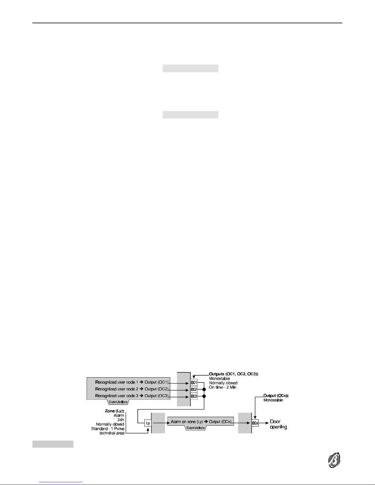
Recognition of multiple codes
The connections and programming described in this section will allow the system to manage multiple codes. This
facility is especially useful in commercial buildings, such as banks where, for security reasons, as many as 3
codes must be entered within 2 minutes (e.g. to open the bank safe, etc.).
+
The connections are as per Figure 53.
Event-Actions The Recognized user code events that refer to the codes must be programmed as follows:
Outputs ON
Recognized user code 1:
Output (OC1)Output (OC1)
Recognized user code 2:
Output (OC2)Output (OC2)
Recognized user code 3:
Output (OC3)Output (OC3)
Program the Alarm on zone event that refers to terminal [Ly] as follows:
Outputs ON
Alarm on zone (Ly):
Output (OCx).Output (OCx).
Zones Program the zone that corresponds to terminal [Ly] as follows:
Alarm
Type: 24h
Balancing: Normally closed
Sensitivity: Standard - Pulses 1
Partition: must be assigned to a partition that is not used by keys, codes or to control operations----this partition
can be considered a Technical partition.
Outputs Outputs corresponding to terminals [OC1], [OC2] and [OC3] should be programmed as follows:
Type: Monostable
Attribute: Normally closed
Time: ON time - 2 Min.
Program the output that corresponds to terminal [OCx] as follows.
Type: Monostable
Program Attribute and Time as per requirements.
As a result of the described connections and programming, activation of output [OCx] will generate the following
events: 24h alarm on panel, Generic alarm on panel and Generic+Tamper alarm on panel.
+
To avoid false alarms----these events must not be assigned to actions.
The bank safe will open when terminal [Ly] opens; that is, when outputs [OC1], [OC2] and [OC3] open simultaneously. These outputs will stay open for 2 minutes. The three codes must be entered within this interval, otherwise,
one of the outputs will close to ground and block input zone [Ly], thus blocking output [OCx] that opens the door.
Figure 53 Recognition of multiple codes
82 Expandable Multifunction Control Panel Omnia
Page 83
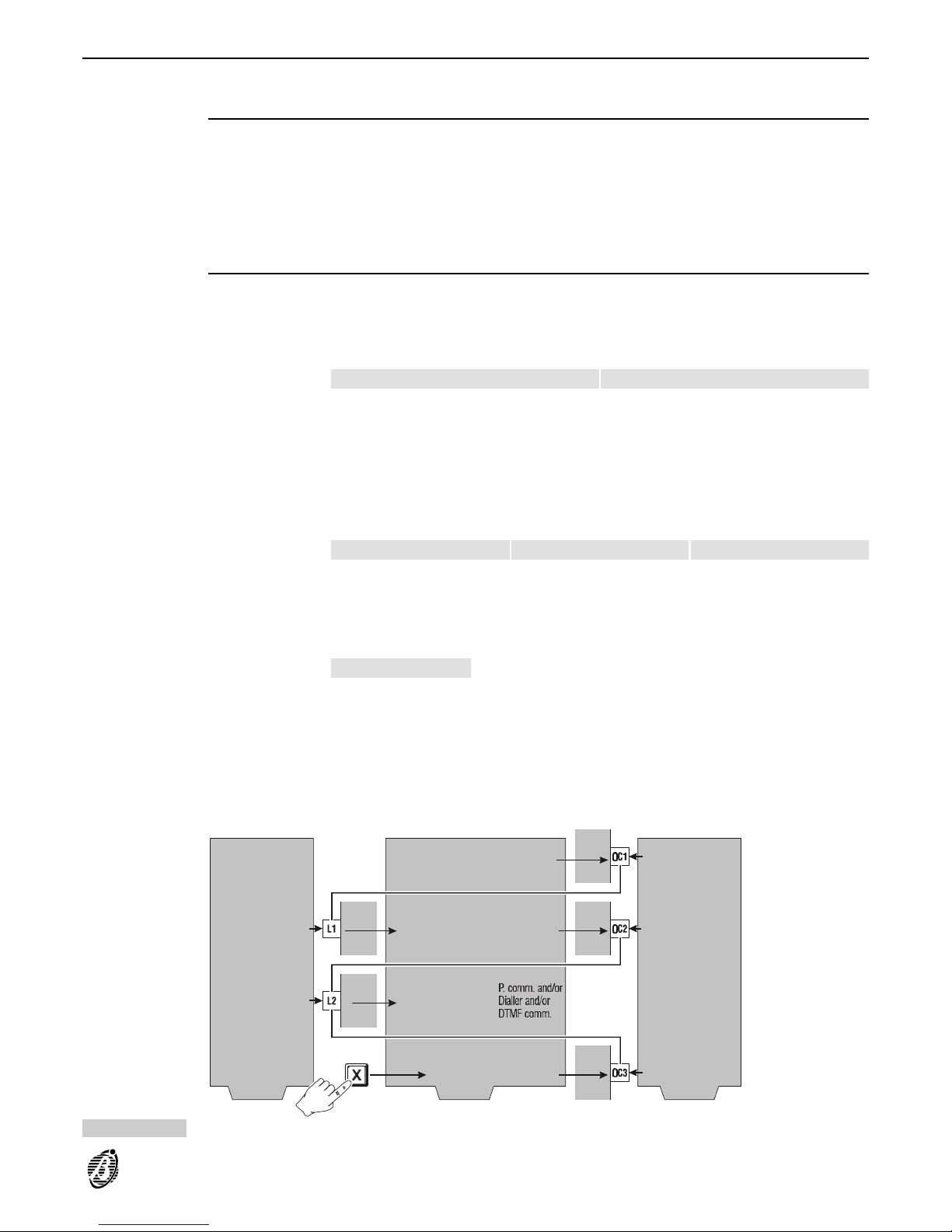
Disarming under duress
The connections and programming described in this section will allow the user to disarm the system and, at the
same time, send a Disarming under duress event to the central station.
Solution no. 1
Program two codes for partition disarming----the first for use in normal circumstances; and the second for use under duress (forced disarming).
Program code 1 for normal disarming and code 2 for Disarming under duress, as follows.
Codes Enable code 2 on the same partitions as code 1.
Event-Actions Assign the Recognized user code 2 event to the required action (Disarm-under- duress) on the Pulse Comm. Di-
aller and/or DTMF communicator.
Solution no. 2
Program an action to signal Disarming under duress. The Duress alert will be sent if the Super key (keypad button) is not pressed within the programmed time.
Connect as per Figure 54 and program as follows.
Zones Program the zones that refer to terminals [L1] and [L2] as follows:
Zone (L1) Zone (L2)
AlarmAlarm AlarmAlarm
Type:
24h24h 24h24h
Balancing:
Normally openNormally open Normally closedNormally closed
Sensitivity:
Standard - Pulses 1Standard - Pulses 1 Low - Pulse 1 Min.Low - Pulse 1 Min.
Partition:
both must belong to a partition that cannot be operated by keys or codes----this partition may
be considered as a Technical partition.
Outputs Program the outputs that refer to terminals [OC1], [OC2]and [OC3] as follows :
Output (OC1) Output (OC2) Output (OC3)
Type:
BistableBistable MonostableMonostable MonostableMonostable
Attribute:
Normally closedNormally closed Normally closedNormally closed Normally openNormally open
Time:
---- 2 Min.2 Min. 2 Min.2 Min.
Event-Actions Program the events as follows:
Outputs ON
Partition no. armed:
Output (OC1)Output (OC1)
Alarm on zone (L1):
Output (OC2)Output (OC2)
Super key no.:
Output (OC3)Output (OC3)
Assign the Alarm on zone (L2) event to the action on the Digital Communicator, Dialler and/or DTMF communica-
tor (for Firmware versions lower than 3.0) to signal disarming under duress.
As a result of the described connections and programming, if the Super key is not pressed----for at least 3 seconds----w ith in 1 minu te o f di sarm ing , th e Disarming under duress event will be generated and the emergency
status will be communicated to the central station.
Area no. armed Output (OC1)
Zone (L1):
Alarm
24h
Normally open
Pulses - 1
technical area
Alarm on zone (L1)
Super key x
Alarm on zone (L2)
Event-Actions Zones Outputs
Output (OC2)
Output (OC3)
Output (OC3):
Monostable
Normally open
On time - 2 Min.
Output (OC1):
Bistable
Normally colsed
Output (OC2):
Monostable
Normally colsed
On time 2 Min.
Zone (L2):
Alarm
24h
Normally closed
Pulse length - 1 Min.
technical area
> 3
secs
Figure 54 Disarming under duress
FACILITIES 83
Page 84

Dialler
The 32 Omnia Dialler actions programmed in the Dialler page can be assigned to events in the Event-Actions
page to signal the start and end of an event.
All dialler actions will send a Voice message (selected from the 14 recordable messages) to up to 16 Telephone
Numbers (selected from the 32 programmable numbers in the Telephone page).
The Dialler feature is extremely useful when the specific Voice messages must be sent to: Police, Fire Brigade,
Gas Company, Installer, Contact persons, etc.
Using the Dialler feature:
Program the Telephone page (Phonebook). This page can store up to 32 telephone numbers----each with a user
identifier label (Description column).
The programmed numbers can be used by the Digital Communicator, the DTMF Communicator (for Firmware versions lower than 3.0) and for Teleservice.
Program the parameters in the Dialler page and relevant windows (Messages and Actions).
Associate the Dialler actions to the Events in the Event-Actions page.
Telephone Program the Telephone page as follows.
Number: Enter the telephone numbers the Dialler must call.
+
In the example (Figure 55), the Police Fire Emergency, the Gas Company, the Installer and contact persons will
be called.
Description: Enter the identifier label----assigned to the telephone number (16 digits maximum).
Used by: indicates the telephone numbers used by the Dialler (Dial.), Digital Communicator (Dig.), DTMF Com-
municator (DTMF) and Teleservice (Tel.).
Other parameters on this page depend on the system.
Dialler Define the following parameters in the Dialler page:
no.: the identifier number represents the corresponding telephone number in the Actions window.
Tel. Num.: enter the identifier numbers of the telephone numbers----programmed in the Telephone page----that
must be called by the dialler.
+
The identifier numbers can be entered in any order. However, the sequence defined under Dialler telephone
numbers determines call priority. Figure 55 shows the Warehouse Alarm Dialler action will send a Warehouse
burg message to: Police Fire Emer----Central Station 1----Central Station 2----Head Office----Branch Office---Alexis Mobile----Summer House.
Description: this field will show the label that corresponds to the identifier number entered in the Tel. Num. col-
umn. The labels can be changed in the Telephone page only.
Other parameters on this page depend on the system. For a more detailed description of these parameters, refer
to the Dialler section.
Click Messages... to assign message labels, as per below.
Click Actions... to program the Dialler actions, as per below.
Assigning message labels and programming Dialler actions:
Messages: assign a label (16 characters maximum) to each of the 14 messages the Panel can record.
+
The OmniaVOX (optional) must be installed for the record, play and delete Voice messages options.
Actions: program the Dialler actions as follows.
no.: this is the identifier number that must be specified in the Event-Actions page, in order to assign the corre-
sponding Dialler action to the events.
1...16: these identifier numbers correspond to the telephone numbers that will be dialled (see no. column under
Dialler telephone numbers----Dialler page). In Figure 55 no. 1 corresponds to Police Fire Emer----no . 2 corre-
sponds to Central Station 1----and so forth.
Each action can be assigned to 1 or more events in the Event-Actions page.
Specify which telephone numbers (1...16)----from the Dialler telephone numbers----will be called and which message will be sent.
An empty box means that the corresponding number will not be called.
Double click (or press ENTER) to select the numbers to be called.
Message: select the Voice message that will be sent for the Dialler action. Enter a number from 1 to 14----the
Descr. Mess. column will show the label assigned in the Messages window.
Descr. Action: assign a label to the Action (16 characters maximum). The label will be shown in the Event-Ac-
tions page.
Figure 55 illustrates:
----Action 6 (Fuse +B Blown) will send the Fuse +B Blown message to telephone numbers: 5 (Branch Office); 6
(Patricia Mobile); 10 (Installer Mobile) and 11 (Installer Office).
84 Expandable Multifunction Control Panel Omnia
Page 85
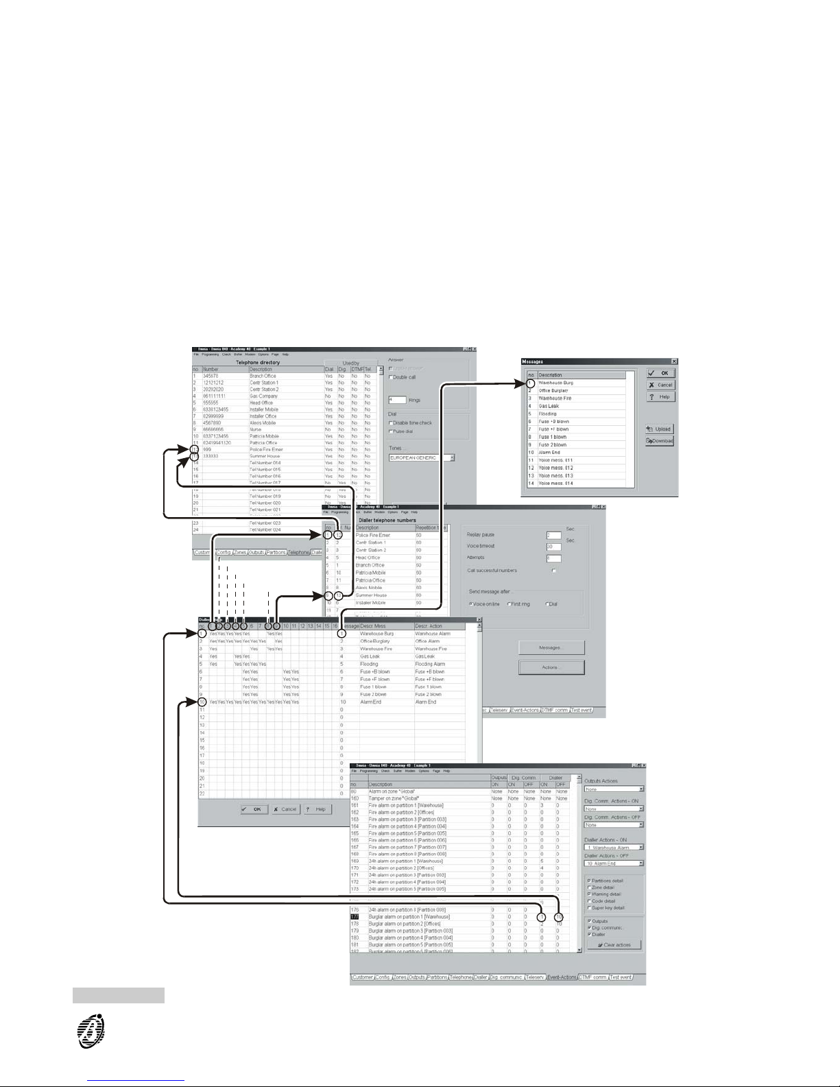
----Action 5 (Flooding Alarm) will send the Flooding message to telephone numbers: 1 (Police Fire Emer);
4 (Head Office); 5 (Branch Office); 6 (Patricia Mobile) and 7 (Patricia Office). Telephone numbers will be dialled in
accordance with call priority.
The examples show how dialler actions operate. However, they must be assigned to one or more events in order
to activate actions.
Event-Actions Use this page to assign the events to the Dialler actions.
Dialler (ON/OFF): Figure 55 illustrates the ON and OFF status of the Dialler. Enter the identifier numbers of the
actions the Dialler must perform----when the associated event occurs and ends. To simplify this operation----u se
the Actions Dialler menu (right side of the page), as follows.
Actions Dialler: this menu is divided in two parts----the upper part is for the actions the Dialler must perform when
the event starts, and the lower part is for the actions the Dialler must perform when the event ends.
Both parts show the Descriptions of the Dialler Action, as illustrated in Figure 55.
Figure 55 Telephone Dialler programming pages
FACILITIES 85
Page 86

To assign the Warehouse Alarm action to the Start of the Burglar alarm on partition 1 [Warehouse] event, and
the Alarm End action to the End of the event, it is necessary to:
Step 1 Select the event.
Step 2 Select Warehouse Alarm from the Dialler Actions - ON menu.
Step 3 Select Alarm End from the Dialler Actions - OFF menu.
This programming will:
send the Warehouse Burg. message to the programmed telephone numbers ( Police Fire Emer----Central Sta-
tion 1----Central Station 2----Head Office----Branch Office----Alexis Mobile----Summer House) when the Burglar
alarm on partition 1 [Warehouse] event starts.
send the Alarm Ens message to the programmed telephone numbers ( Police Fire Emer----Central Station 1----
Central Station 2----Head Office----Branch Office----Alexis Mobile----Summer House----Installer Mobile----Installer Office) when the alarm ends.
With reference to the examples----actions 5 and 6 are assigned to 24h alarm on partition 1 (Warehouse) and
Warning fuse +B events respectively.
+
Select Events on the Dialler actions page to view the events that will generate the selected Dialler action.
86 Expandable Multifunction Control Panel Omnia
Page 87

Stop Alarm by Key/Card
The connections and programming described in this section will allow the user to stop Outputs (Horns, Strobes, etc.)
and calls, by using a valid key/card at a enabled reader (enabled on the partition in Alarm status). This facility is especially useful in the event of false alarms.
The following example shows how to programa key/card to stop the outputs and clear the call queue.
+
The connections are as per Figure 56.
The examples utilizes:
Event no. 256: Valid key on partition 1
Output no. 4: refers to terminal [OC2] of the Main unit
Zone no. 6: refers to terminal [L6] of the Main unit
Event-Actions Programming for event no. 256----Valid key on partition 1:
Outputs ON: 4
Outputs Programming for output no. 4:
Type: Monostable
Attributes: Normally closed
Time: On Time 1 Sec.
Zones Programming for Zone no. 6:
Command:
Clear call queue
Balancing: Normally closed
Sensitivity: Standard
As a result of the described connections and programming, keys/cards (enabled on the partitions in alarm status)
will stop all the Alarm events and clear the call queue, when used at an enabled reader.
If alarm status persists, after removal of the key/card----alarm status signalling will restart as per programming (output activation, telephone calls, etc.).
+
Valid keys/cards can stop zone and partition alarms but cannot stop Panel alarms, unless the Stop alarm by
digital key option is enabled.
If partition and Panel alarms activate the same output (Generic alarm on partition no. and Generic alarm on
panel), and both alarms are active----the key/card will stop the Generic alarm on partition no. event but not the
Generic alarm on panel event, therefore, the output (e.g. Siren) will not be deactivated.
+
These solutions can stop alarm events and outputs, but cannot delete the alarm memory. To Alarm memory can
be deleted by means of the Alarm reset command from the keypads USER MENU. The Alarm memory will be deleted automatically, when the partitions are next armed.
L 6L 6
Main unit
Output n. 4:
Monostable
Normally closed
On time - 1 Sec.
Zone n. 6:
Command
Clear call queue
Normally closed
Pulses - 1
Figure 56 Stop Alarm by key
FACILITIES 87
Page 88

BENTEL SECURITY s.r.l.
C.da Ravigliano, Z.I. S.Scolastica
64013 CORROPOLI (TE) - ITALY
Tel.: +39 0861 839060
Fax: +39 0861 839065
e-mail: [email protected]
http://www.bentelsecurity.com ISTOMNIAINS-UK 4.1 020703 V4.2
 Loading...