

Page 1

BENSON CABINET
HEATER
NATURALGAS (G20 I2H)
PROPANE GAS (G31 I
3
P)
I N S T A L L A T I O N C O M M I S S I O N I N G
S E R V I C I N G
U S E R I N S T R U C T I O N S
July 2010
Issue 11
THIS MANUAL SHOULD BE LEFT WITH THE END USER .
TO ENSURE SERVICE AND MAINTENANCE INFORMATION IS AVAILABLE ON SITE
Page 2

1.0 Compliance Notices 4
1.1 Certificates of Conformity 5
1.2 General Product Information 5
1.3 General Requirements 5
1.4 Delivery & Pre inspection 6
1.5 Warranty 6
2.0 Location & Positioning 7
2.1 Gas Supply 9
2.2 Electrical Supply 9
2.3 Air Supply 9
2.4 Minimum Space Requirements 12
2.5 Air Distribution System 12
2.6 Flue System 13
2.7 Flue Installation 17
3.0 Installation 17
3.1 Packaging & Siting 17
3.2 Flooring 17
3.3 Minimum Clearances 17
3.4 Assembly 17
3.5 Gas Installation & Connection 18
3.6 Electrical Installation & Connection 18
3.7 Air Distribution Installation 18
3.8 Warm Air Registers 18
3.9 Heater Control Installation 19
4.0 Commissioning 19
4.1 Pre test 19
4.2 Ignition 20
4.3 Air Delivery System 22
4.4 Hand Over 22
5.0 Servicing 23
5.1 Planned Servicing 23
5.2 Servicing procedure Major Components 23
5.3 Service Re commissioning 27
6.0 Fault Diagnosis By Flow Chart 28
7.0 Wiring Diagrams 30
8.0 Technical Data 36
CONTENTS
8.1 Cabinet Range Technical Data 39
9.0 Reference Documents Standards & Codes of Practice 43
9.1 Parts Listing 44
Page 3

~ C O N T E N T S ~
S E C T I O N 1
1.0 Compliance Notices 4
1.1 Certificates of Conformity 5
1.2 General Product Information 5
1.3 General Requirements 5
1.4 Delivery & Pre-installation Checks 6
1.5 Warranty 6
2.0 Location & Positioning 7
2.1 Gas Supply 9
2.2 Electrical Supply 9
2.3 Air Supply 9
2.4 Minimum Space Requirements 12
2.5 Air Distribution System 12
2.6 Flue System 13
2.7 Flue Installation 13
3.0 Installation 16
3.1 Packaging & Siting 16
3.2 Flooring 16
3.3 Minimum Clearances 16
3.4 Assembly 16
3.5 Gas Installation and Connection 17
3.6 Electrical Installation & Connection 17
3.7 Air Distribution Installation 17
3.8 Warm Air Registers 17
3.9 Heater Control Installation 18
4.0 Commissioning 18
4.1 Pre-Test 18
4.2 Ignition 19
4.3 Air Delivery System 21
4.4 Hand Over 21
5.0 Servicing 22
5.1 Planned Servicing 22
5.2 Servicing Procedure - Major Component Parts 22
5.3 Servicing - Re-commissioning 25
6.0 Fault Diagnosis By Flow Charts 26
7.0 Wiring Diagrams by Model and Burner Type 28
8.0 Technical Data Net Efficiency Calculations 35
8.1 Benson Cabinet Range Data 36
9.0 Reference Documents Standards, Codes of Practice 39
9.1 Parts Listing 40
S E C T I O N 2
10.0 Introduction
10.1 Commissioning/hand over
10.2 Servicing
10.3 Start up procedure
10.4 Stop procedure
10.5 Shutdown procedure
10.6 Ventilation only
10.7 Lockout situations
10.8 Contact Information
I L L U S T R A T I O N S
Page No
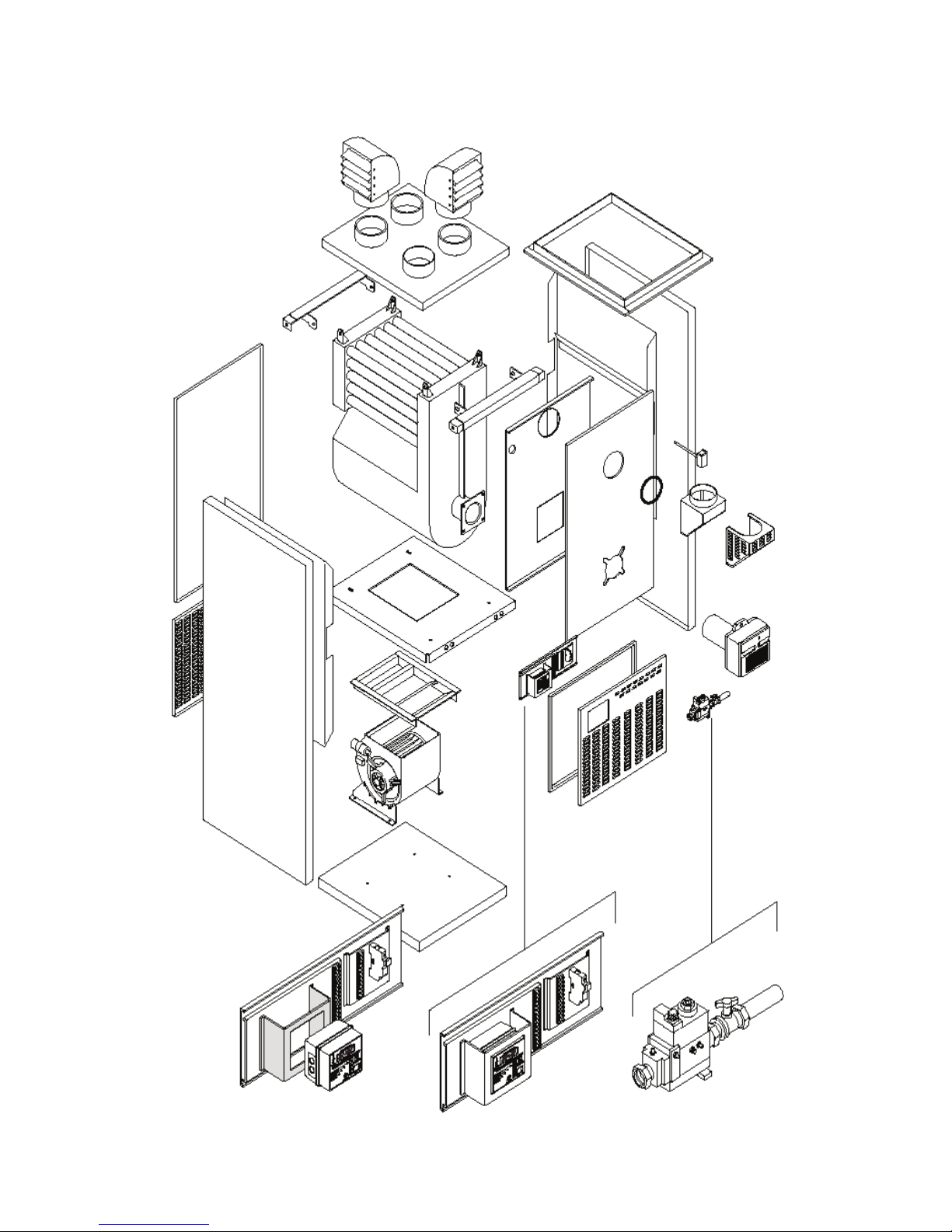
Exploded view 8
Flue Systems 14-15
Fan and Motor Configurations 23
Fault Diagnosis Flow Charts 26
Wiring Diagrams 28
Any reference made to Laws, Standards, Directives , Codes of Practice or other
recommendations governing the application and installation of heating appliances and
which may be referred to in Brochures, Specifications, Quotations, and Installation,
Operation and Maintenance manuals is done so for information and guidance purposes only
and should only be considered valid at the time of the publication. Benson Heating cannot
be held responsible from any matters arising from the revision to or introduction of new
Laws, Standards, Directives, Codes of Practice or other recommendations.
IMPORTANT NOTICE TO INSTALLERS
Installers should satisfy themselves that the gas pipework installation is carried out in
accordance with all current legislation, Codes of Practice and
recommendations .
Additionally it may be necessary to protect the gas valves which form part of
the heater or burner assembly from potential pipe contamination particularly,
but not exclusively , where copper gas pipework is used.
In instances where copper pipework is to be used for all or part of a gas
pipework installation, including short length final connections then we advise
that installers consult with gas supplier or provider and satisfy themselves what
additional precautions may be necessary
Page 4

1.0 Compliance notices
The Benson Gas fired Cabinet Heaters
detailed herewith are manufactured by
Benson Heating Within a strictly controlled
quality environment within the parameters of
ISO 9001.
These instructions are only valid if the
following country code is on the appliance
GB. IE. If this code is not present on the
appliance, it is necessary to refer to the
technical instructions which will provide the
necessary information concerning the
modification of then appliance to the
conditions of use for the country.
The Benson range has been tested and
assessed for compliance with the following
European Directives.
Gas Appliance Directive (90/396/ EEC)
Machinery Directive (89/392/EEC)
Low Voltage Directive (73/23/EEC)
& (93/68/EEC)
Electromagnetic Compatibility Directive
(89/336/EEC & 91/31/EEC)
Product Liability Directive (65/374/EEC)
The manufacturer has taken reasonable and
practical steps to ensure that Benson
Cabinet Heaters are safe and without risk
when properly used. These heaters should
therefore only be used in the manner and
purpose for which they were intended, and in
accordance with the recommendations
detailed herewith.
The heaters have been designed,
manufactured, assembled, inspected, and
tested, with safety and quality in mind, there
are certain basic precautions which the
installer and user should be aware of, and
they are strongly advised to read the
appropriate sections of the information pack
accompanying the heater, prior to installation
or use.
Benson Heating supports all new products
being supplied to their customers with a
comprehensive information pack; this clearly
defines mandatory instructions for the safe
installation, use, and maintenance, of the
appliance(s).
Where proprietary items are incorporated
into Benson Heating products, detailed
information and instructions are also
provided as part of the information pack.
It is the responsibility of the installer, owner,
user, or hirer, of such products supplied by
Benson Heating, to ensure that they are
familiar with the appropriate information/
manuals, supplied by the manufacturer, and
that they are suitably aware of the purpose of
the manuals and the safety instructions. In
addition, operators must be suitably trained
in the use of the appliance so as to ensure its
continued safe and efficient use.
Benson Heating has a commitment to
continuous improvement, and therefore
reserves the right to amend or change the
specification of the Cabinet Heater range
subject to compliance with the appropriate
European, national, and local regulations.
Contained within the text of the manual, the
words 'Caution' and 'Warning' are used to
highlight certain points.
Caution is used when failure to follow or
implement the instruction (s) can lead to
premature failure or damage to the heater or
its component parts.
Warning is used when failure to heed or
implement the instruction (s) can lead to not
only component damage, but also to a
hazardous situation being created where
there is a risk of personal injury.
NOTE
THE WARRANTY REGISTRATION CARD
SUPPLIED WITH THE HEATER MUST BE
COMPLETED AND RETURNED
TO BENSON HEATING ON COMPLETION
OF COMMISSIONING
Warranty claims made without this
condition being fulfilled will not be
processed
The Benson range of Gas fired Cabinet
Heaters conform to the following harmonised
standards;
Page 5

BS EN 1020 Requirements for non
domestic gas fired forced convection air
heaters for space heating incorporating a fan
to assist transportation of combustion air
and/or combustion products.
BS EN 292 - Part 1 : 1991
Safety of Machinery - Basic Concepts,
General Principles for Design Basic
terminology, methodology
BS EN 292 - Part 2 : 1991
Safety of Machinery - Basic Concepts,
General Principles for Design
Technical Principles and Specifications
BS EN 60204 - Part 1 : 1993
Safety of Machinery - Electrical Equipment
for Machines Specification for General
Requirements
BS EN 60335 - Part 1 : 1988
Safety of Household and Similar Electrical
Appliances General Requirements
BS EN 55014 - 1993
Limits and methods of measurement of radio
disturbance characteristics of electrical
motor-operated and thermal appliances for
household and similar purposes, electrical
tools and similar electric apparatus
BS EN 50165 - 1997
Electrical Equipment of non-electric heating
appliances for household and similar
purposes, safety requirements
1.1 Certificates of conformity
Certificates are available from the Quality
Control Department at Benson Heating.
Notified body Pin reference is 63AQ0533.
1.2 General product information
The Benson range of indirect gas fired forced
convection heaters have an output range
from approximately 29.3 kW to 381.0 kW and
are available in a configuration that will allow
for down flow, horizontal, floor mounting, or
above ground level on purpose built steel
supports.
The units can suit either ducted applications,
or be used as free blowing units, but each
heater must be connected to its own
individual open flue.
Each heater is fitted with a forced draught
burner which has been test fired and pre-set
prior to despatch. The safety functions of the
burner are by way of a fully sequential
control box fitted to the burner.
Note
Neither asbestos nor soft soldered joints are
used in the construction or manufacture of
the Benson range of Cabinet Heaters. The
materials selected for use can withstand the
mechanical, chemical, and thermal stresses
which they will be subject to during foreseen
normal use when installed in accordance
with the manufacturers recommendations
.
1.3 General requirements
Caution
Before installation, check that the local
distribution conditions, nature of gas and
pressure, and the current state adjustment of
the appliance are compatible.
Installation, commissioning, and servicing
must only be carried out by appropriately
qualified and competent persons.
Warning
Unauthorised modifications to the appliance,
or departure from the manufacturers
guidance on intended use, or, installation
contrary to the manufacturers
recommendations may constitute a hazard.
Note
To ignore the warning and caution notices,
and to ignore the advice from the
manufacturer on installation, commissioning,
servicing, or use, will jeopardise any
applicable warranty, moreover, such a
situation could also compromise the safe and
efficient running of the appliance itself, and
thereby constitute a hazard.
The installation of the appliance must meet
all the relevant European, national, and local
criteria. (See sections 3 and 9).
Prior to installation the following points
should be considered;
Page 6

a) The position of the heater for the optimum
efficient distribution and circulation of warm
air
b) The position of the heater relative to the
route of the flue
c) The position of the heater relative to the
supply of gas
d) The position of the heater relative to the
electrical services, and if appropriate, any
additional controls.
e) The position of the heater relative to the
supply of fresh air
f) The height if applicable at which the heater
is to be mounted and potential stratification /
circulation problems.
g) The position of the heater relative to
service and maintenance requirements
Caution
The heater must not be installed within an
area where the conditions are unsuitable,
e.g. where the atmosphere is highly
corrosive, has a high degree of salinity, or
where high wind velocities may affect burner
operation. Suitable protection should be
provided for the appliance when it is located
in a position where it may be susceptible to
external mechanical damage from; for
example, fork lift trucks, overhead cranes
etc.
1.4 Delivery and pre-installation
checks
The heater is supplied wrapped in heavy
duty protective polythene. On receipt of the
heater, the following checks should be
carried out;
a) The model is as per order
b) That it is undamaged
c) That it is suitable for the fuel supply
d) That it is suitable for the electrical supply
If any of these points are not satisfied then
contact should be made with the Sales Office
at Benson Heating as soon as possible by
telephoning 01547-528534. In the case of
claims for damage, this must be signed for
as damaged and reported in writing within 24
hours of delivery, in order to comply with
insurance criteria
1.5 Warranty
The heater is supplied with a 2 year warranty
made up as follows; first year covering parts
and labour, and second year covering parts
only. In addition to this there is also a 10 year
time related warranty on the combustion
chamber/heat exchanger. The warranty
commences from the date of despatch from
the manufacturer, and is subject to the terms
detailed within the Benson Heating
'conditions of business'.
Note (i)
The warranty may be invalidated if a) The warranty registration/commissioning
card has not been completed and returned to
Benson Heating
b) The installation is not in accordance with
the general requirements of this manual
c) The flue arrangement and air supply for
the heater are not in accordance with the
manufacturers
recommendations, codes of practice, or
similar standards
d) Air flow through the heater is not in
accordance with the manufacturers technical
specifications
e) Internal wiring on the heater has been
tampered with or unauthorised service or
repairs undertaken
f) The main electrical supply input to the
heater has been interrupted during the
heating mode
g) The heater has been subject to and
affected by the ingress of water in any form
h) The heater is not operated at the rating(s)
laid down in the manufacturers technical
specifications
i) The heater has not been operated or used
within the normal scope of its intended
application
Page 7

j) The manufacturer's recommended
minimum service requirements have not
been complied with
Note (ii)
All warranty claims must contain the
following information to enable processing to
take place;
(1) Heater model
(2) Heater serial number
(3) Order reference/date of order, together
with full installation details (name and
address)
(4) Details or symptoms of fault
(5) Installers name and address.
Faulty parts must be returned to the Knighton
Spares Department, the address of which is
provided in Section 2 of this manual. Any
such parts will undergo inspection to verify
the claim. Replacement parts supplied prior
to this may be charged, and a credit supplied
upon subsequent validation of the warranty
claim.
Consumable items are specifically not
included within the scope of the warranty.
Note (iii)
Notification is required immediately a fault is
suspected.
The manufacturer will not accept
responsibility for any additional damage that
has been caused, expense incurred, or
consequential loss resulting from any failure
of the heater(s).
2.0 Location / Positioning
Warning
All of the basic criteria must be satisfied prior
to commencing installation and
commissioning, additionally, the Cabinet
Heater must be positioned and installed so
as to comply with all the relevant standards
and guide lines (see section 9.0), as well as
meeting national and local fire regulations
and insurance criteria, especially if it is
proposed that the heater is to be installed
within a special risk area (e.g. proximity to
where petrol engined vehicles are stored or
parked, where cellulose spraying takes
place, where woodworking machinery is
operated, etc,).
Indirect fired heaters must not be located in
hazardous areas, however, it is permissible
for the heater to supply air to such areas.
The heater must not be installed within an
environment where there is a high
concentration of chlorides, fluorides, salts, or
other aggressive or volatile chemicals /
compounds. Nor should the heater be
positioned where the burner could be
adversely affected by high winds or draughts.
The location chosen for the heater must
allow for the fitting of an effective flue
system.
The location must also allow for adequate
clearance for the air supply, return air
circulation, oil supply, electrical supply, whilst
also providing good and safe working
access. The heater must be installed on a
flat and level surface made from noncombustible material, which is sufficiently
robust to withstand the weight of the heater
and any ancillary equipment. Any
combustible material adjacent to the heater
or flue system must be so placed or shielded
so that its surface temperature does not
exceed 65
o
C.
In areas where it is proposed that more than
one heater is to be installed, a general
scheme of circulation should be drawn up
and maintained, thereby offering the best
heat distribution.
All Benson Heaters are fitted with a pressure
relief facility, this is incorporated into the
design of the flue gas exit duct. Care should
therefore be taken in siting service
connections and controls well away from the
pressure relief vent.
Warning
Under no circumstances must the pressure
relief be restricted, blocked, or have the free
exit of exhaust gas impaired or re-directed.
Page 8
Page 9

2.1 Gas supply - general
The Benson range of gas fired cabinet
heaters are all manufactured and pre-set for
use with natural gas or LPG classified under
the categories, based upon the destination of
the heater see section 8.0
The heater must be compatible with the gas
supply, and each heater must be installed
with a separate approved isolating gas cock
positioned adjacent to and upstream of the
union between the service pipe and the
heater.
The gas supplier should have been
contacted to confirm that the supply feed
(pipework and metering) is capable of
delivering the required dynamic volume of
gas, thereby ensuring that the minimum
burner pressure can be achieved.
Consideration should have also been given
to the pressure drop on single and multiple
heater installations, and the affect that such
installations will have upon other plant
sharing the gas supply.
If it is necessary to fit a gas booster, the
controls must include a low pressure cut-off
switch which must be fitted on the supply
side of the booster. It is also a requirement
that the gas supplier is contacted prior to the
fitting of the unit.
Note
Reference to the Institute of Gas Engineers
publication UP-1 and UP-2 together with
BS6891 is strongly advised.
Service and Installation pipework must be of
a diameter equal to or greater than the inlet
connection on the heater, all joints must be
sealed using an approved sealing
compound, and the system purged and
tested for soundness.
2.2 Electrical supply
Wiring external to the cabinet heater must be
installed in accordance with any local,
national, and European regulations, as well
as meeting the appropriate requirements of
IEE regulations.
The means of connection to the main
electrical supply must allow for complete
electrical isolation of the heater, furthermore,
in the case of a unit wired for a three phase
supply, the supply should only be used to
serve the heater itself and no other plant or
equipment.
The position of the isolation switch must be
such that it is adjacent to the heater and
easily accessible at all times. In addition, the
isolator itself must have a contact separation
of not less than 3mm as per BS5991
clause 20.2.
The Control Fuse ratings are detailed on the
appliance data plate.
Warning Ensure that the electric and gas
supplies are turned off before any electrical
work is carried out on the heater. Ensure
that wiring cannot make contact with any
surfaces liable to be subject to high
temperatures or where the insulation of the
wiring could be impaired as a result of such
contact.
All Cabinet Heaters must be earthed.
Caution
The main electrical supply must not be
switched off or disconnected as a method for
stopping the heater, the exception to this is in
an emergency, or during servicing, when the
heat exchanger has been allowed to cool
sufficiently to prevent any damage from
occurring. Claims for damage will not be
considered if they have resulted from
incorrect wiring or the incorrect use of the
heater.
2.3 Air supply
Consideration must be given to the provision
of air for the purposes of combustion and
ventilation of the heated space, plant room or
enclosure where heaters are to be installed
Note
It is strongly recommended that BS 6230 :
2005 is referred to for further information
concerning ventilation requirements
Where mechanical ventilation is used it is a
requirement that the inlet is of the
mechanical type, and the outlet is either
mechanical or natural.
Page 10
2.3.1 Heaters installed within the
heated space
Where heaters are installed within the space
to be heated (I.e. not a plant room or
enclosure
Combustion air or heater related ventilation
air
Will not be required if
The design air change rate of the heated
space is 0.5 air changes per hour or greater
The design air change rate may be satisfied
by natural infiltration or by mechanical
ventilation
Combustion and General ventilation
will be required if
The design air change rate of the heated
space is less than 0.5 air changes per hour
Where the heated space has an air change
rate of less than 0.5 air changes per hour
then it will be necessary to provide either
natural ventilation openings to the heated
space (section 2.3.1.1. refers) or the
mechanical ventilation of the heated space
(section 2.3.1.2. refers)
2.3.1.1 Natural Ventilation Openings to
the Heated Space
If the heated space design air change rate is
less than 0.5 air changes per hour then
provision for low level natural ventilation
openings will only be necessary
The minimum free area of the low level
natural ventilation opening shall be
2cm
2
for each kW of rated heat input
The low level natural ventilation opening
should be situated on an external wall and be
within 1000 mm of floor level for natural gas
and ideally at floor level for l.p.g gas
installations but in any event no higher than
250 mm.
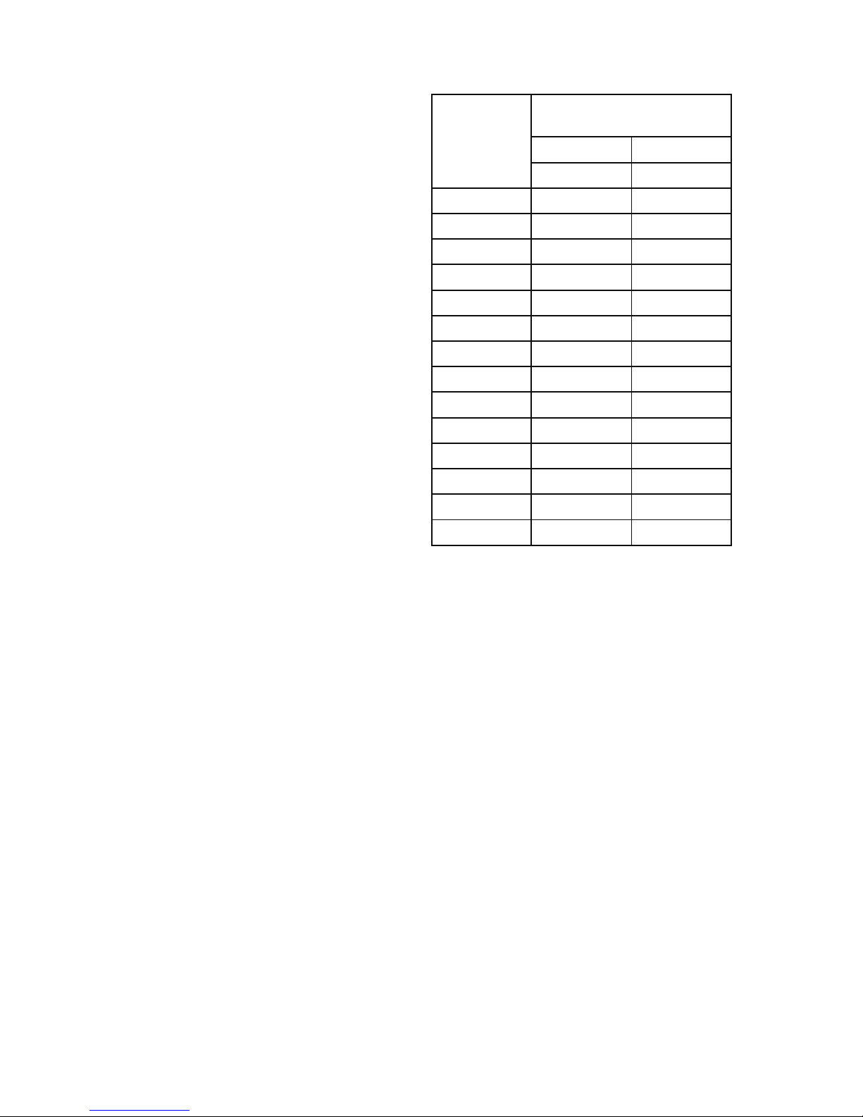
The table in the next column provides
specific data for each heater model as -
2.3.1.2
Mechanical Ventilation to the Heated
Space
In the event that the heated space has a
design air change of less than 0.5 air
changes per hour and that installer prefers to
mechanically ventilate the heated space
rather than provide ventilation openings then
-
The heated space needs to be
mechanically ventilated so that the
design air change is 0.5 air changes or
greater.
It is a requirement that the mechanical
ventilation shall be of the ’input’ type
with either natural or mechanical
extraction.
Systems of mechanical extraction with
a natural inlet shall not be used
It is necessary to provide an automatic
means to safely inhibit heater(s)
operation should mechanical air supply
fail for any reason
Minimum Free Area of
ventilation opening
High Level Low Level
cm2 cm2
100 None 64
125 None 79
150 None 97
200 None 127
250 None 160
300 None 193
400 None 257
500 None 291
600 None 386
700 None 460
800 None 515
1000 None 623
1200 None 769
1300 None 847
Model
Page 11
2.3.2. Heaters Installed within a Plant
Room or Enclosure
A plant room means a room housing the
heater plant and probably other items of
building service plant and would generally
have generous space for maintenance
An enclosure is where the heater is installed
within a compartment or confined area where
space is limited
Where heaters are installed within a plant
room or enclosure then provision for both
combustion air and air for general ventilation
will be required by means of high and low
level ventilation openings (sections 2.3.2.1
refers to plant room applications and
sections 2.3.2.2 refers to enclosure
applications).
Alternatively the plant room or enclosure may
be mechanically ventilated (section 2.3.2.3
refers)
2.3.2.1 Natural Ventilation Openings to
Plant Rooms
For plant room applications the minimum free
area of ventilation opening shall be
At high level 2 cm
2
for each kW of
rated heat input
At low level 4 cm
2
for each kW of rated
heat input
The high level ventilation opening should be
sited on an external wall and positioned as
high as is practical and always within the top
15% of the wall height
The low level natural ventilation opening
should be situated on an external wall and be
within 1000 mm of floor level for natural gas
and ideally at floor level for l.p.g gas
installations but in any event no higher than
250 mm.
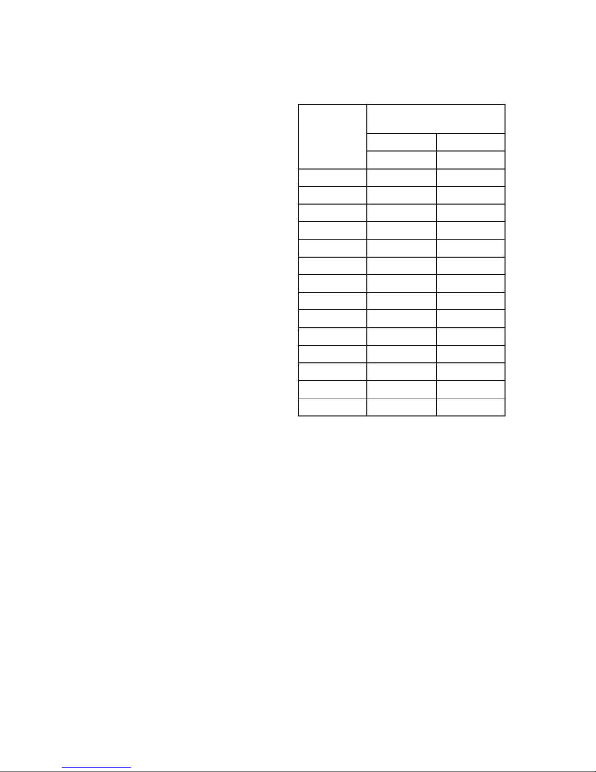
The table below provides specific data for
each heater model as -
2.3.2.2 Natural Ventilation Openings to
Enclosures
For enclosure applications the minimum free
area of ventilation opening shall be
At high level 5 cm
2
for each kW of
rated heat input
At low level 10 cm
2
for each kW of
rated heat input
The high level ventilation opening should be
sited on an external wall and positioned as
high as is practical and always within the top
15% of the wall height
The low level natural ventilation opening
should be situated on an external wall and be
within 1000 mm of floor level for natural gas
and ideally at floor level for l.p.g gas
installations but in any event no higher than
250 mm.
The table below provides specific data for
each heater model as
Minimum Free Area of
ventilation opening
High Level Low Level
cm2 cm2
100 64 128
125 79 158
150 97 194
200 127 254
250 160 320
300 193 386
400 257 514
500 291 582
600 386 722
700 460 920
800 515 1030
1000 623 1246
1200 769 1538
1300 847 1694
Model
Page 12
2.3.2.3 Mechanical Ventilation to a
Plant Room or Enclosure
In the event that the installer prefers to
mechanically ventilate the plant room or
enclosure rather than provide ventilation
openings then -
The plant room or enclosure needs to
be mechanically ventilated at the rate
of 4.14 m
3
/h of fresh air per kW or
rated heat input.
It is a requirement that the mechanical
ventilation shall be of the ’input’ type
with either natural or mechanical
extraction. Where mechanical
extraction is selected then the
extraction rate should be 5%-10% less
than the input rate.
Systems of mechanical extraction with
a natural inlet shall not be used
It is necessary to provide an automatic
means to safely inhibit heater(s)
operation should mechanical air supply
fail for any reason
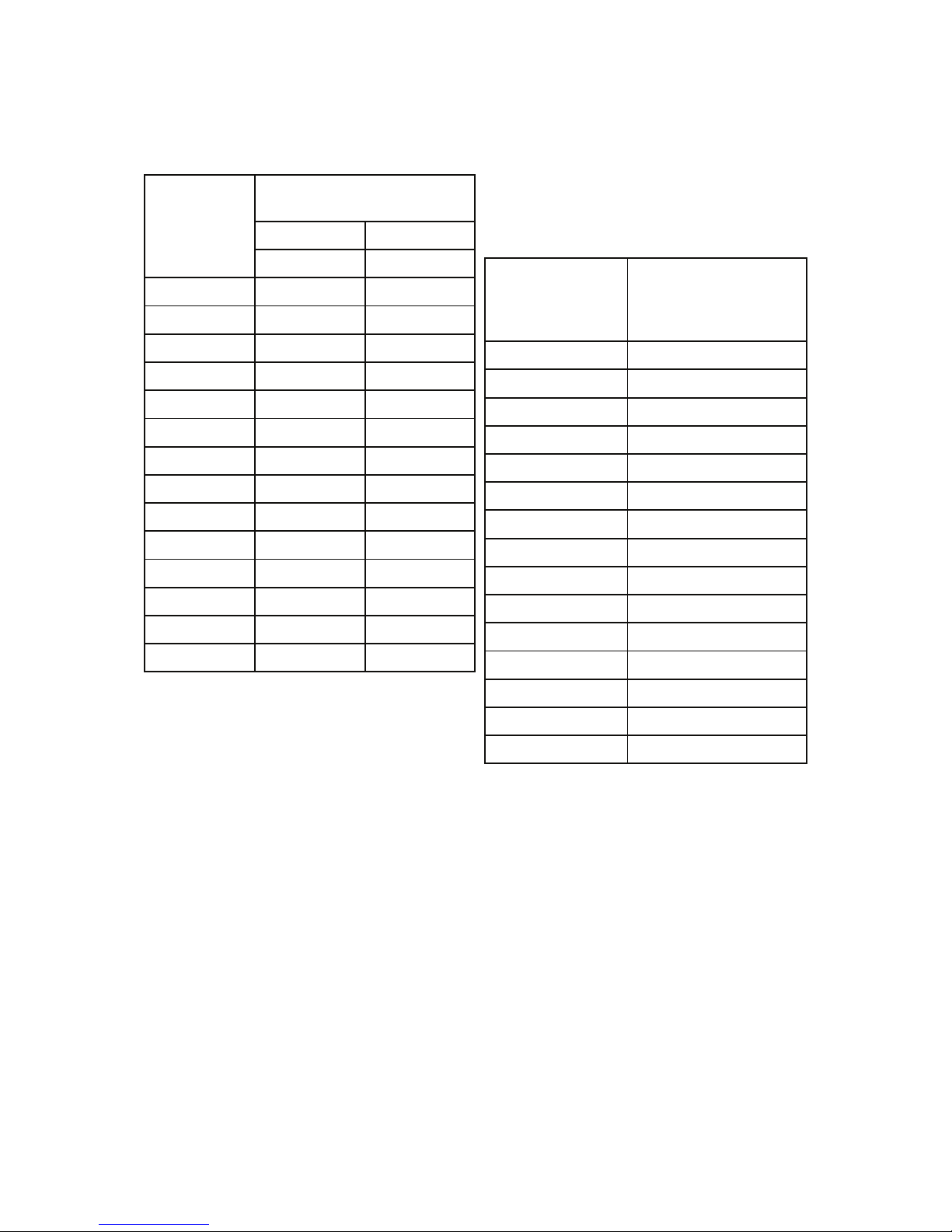
The table below provides specific data for
each heater model as -
2.4 Minimum space requirements
The minimum space requirements for single
and multiple heater applications are detailed
in section 3.3 later within this manual.
2.5 Air distribution system
All materials used within the construction of
the delivery and return air ducts must not
represent a fire hazard and should be made
from thermally inert materials. The selection
of materials must take account of the
environment into which the heater and its air
delivery system is expected to work, it must
also take account of the stresses and
loadings placed upon it during its normal
working life Where interjoist spaces are used
to route ducting these must be lined with fire
resistant insulation material.
In installations where forced recirculation is a
Minimum Free Area of
ventilation opening
High Level Low Level
cm2 cm2
100 159 318
125 198 396
150 244 488
200 317 634
250 400 800
300 483 966
400 643 1286
500 726 1452
600 965 1930
700 1152 2304
800 1287 2574
1000 1558 3116
1200 1922 3844
1300 2118 4236
Model
MODEL
Mechanical
Ventilation Rate for
Plant Room or
Enclosure
125 164
150 202
200 262
250 331
300 400
400 533
500 601
600 799
700 954
800 1066
1000 1290
1200 1592
1300 1753
100 132
M3/h
Page 13

feature, a full and unobstructed return air
path to the heater(s) must be provided, with
return air grilles connected by ducting directly
to the return air inlet on the heater. The limit
for recirculation should not be greater than
85% recirculated air to 15% fresh air.
Where the heater is installed within a
enclosure or plant room the return air and
discharge air arrangement must be such that
the air circulation fan does not interfere with
the operation of the flue. The return air intake
and warm air outlet should therefore be fully
ducted to and from the heater, respectively,
within the compartment or plant room.
If the inlet air is ducted to the outside, then
the lowest edge of the inlet air duct must be
at least 500 mm above the outside floor or
ground level, it must also be fitted with an
access point (s) to allow for cleaning and
servicing to occur. The openings in the
structure of the plant room, through which
the ductwork passes must be of fire resistant
material and constructed to prevent the
likelihood of any fire from spreading.
In ducted applications the ductwork must be
designed so as to give a static pressure
within the limits stated in section 8 of this
manual. It should be noted that if the static
pressure is too high, nuisance shut-down will
occur when the heater goes out on the
overheat limit thermostat, if the static
pressure is too low, then damage can be
caused to the fan motor.
Warm air outlets on ducted applications must
be such that they cannot be closed or
become blocked, which again would lead to
an increase in static pressure and nuisance
shutdown.
The outlets must not be sited so that warm
air can be discharged onto combustible
materials, if necessary, guard rails should be
used to ensure that effected areas are kept
clear. Return air intakes must not be located
so that potentially harmful or hazardous
contaminated air can be drawn into the
system.
2.6 Flue system
It is essential that the products of combustion
are flued to the outside of the building. Each
heater must have its own separate flue, with
a flue diameter of not less than is detailed in
section 8 within this manual.
the minimum vertical length of flue must not
be less than 3m. The flue should rise
vertically, and the number of bends should
be kept to a minimum.
Flue pipe should be supported at intervals
not exceeding 1.8mtrs
Flue pipes below a height of 2 m should
be guarded against the possibility of
being accidentally touched when hot by
personnel
It is strongly advised that BS 5854; 1980,
and BS 5440; parts 1 and 2, are used as
consultative documents when considering
flue requirements.
Care should be taken to ensure that the flue
terminal is not situated in a high pressure
area, the proximity of buildings and other
obstacles which will influence this must be
taken into account, preferably at the design
stage. See figures 2-12.
Provision must be made for the
disconnection of the flue for inspection and
service requirements, and it is strongly
advised that where bends are fitted
inspection covers are included. The materials
from which the flue is constructed must be
non-combustible, resistant to internal and
external corrosion, and be capable of
withstanding the stresses and loadings
associated with normal use.
When designing the flue system the
prevention of the formation and entrapment
of condensation must be a key consideration.
Twin wall or insulated systems are
recommended as they tend to inhibit the
formation of condensates.
Where condensation is unavoidable traps
should be included to encourage the
condensates to flow freely to a point from
which they may be released, preferably into
a gully. The condensate pipe from the flue to
the disposal point must be made from
corrosion resistant pipe of not less than
25 mm internal diameter.
Page 14

If the flue passes through a wall, ceiling, or
roof made from combustible material then it
has to be sleeved so as to provide a
minimum of a 25 mm void between the
exterior of the flue and the internal wall of the
sleeve. The maximum permitted temperature
of any adjacent combustible material is 65
o
C.
The position of the flue and its terminal
should be such that it does not impair the
combustion process.
It should terminate in an exposed position so
as to allow the escape and dissipation of flue
gases without risk of their re-entering the
property through windows, ventilation ports,
etc,.
The flue should extend to at least 1m above
the height of any object within 3,5m of the
terminal.
Flue terminals should be fitted on all flues
with a diameter of 200 mm or less. The
terminal must be of the approved type, and
have outlet grilles on all sides giving a total
free area of at least double that of the flue.
Caution
It is imperative that the flue should be
properly sealed where it passes through the
roof, this can best be achieved by using the
approved method of roof flashing plate and
cravat.
Note
It should be noted that claims made under
warranty and attributed to the ingress of
water may not be considered especially if an
approved method of sealing has not been
used, or if the design of the flue has not
made provision for possible condensation
problems
Page 15
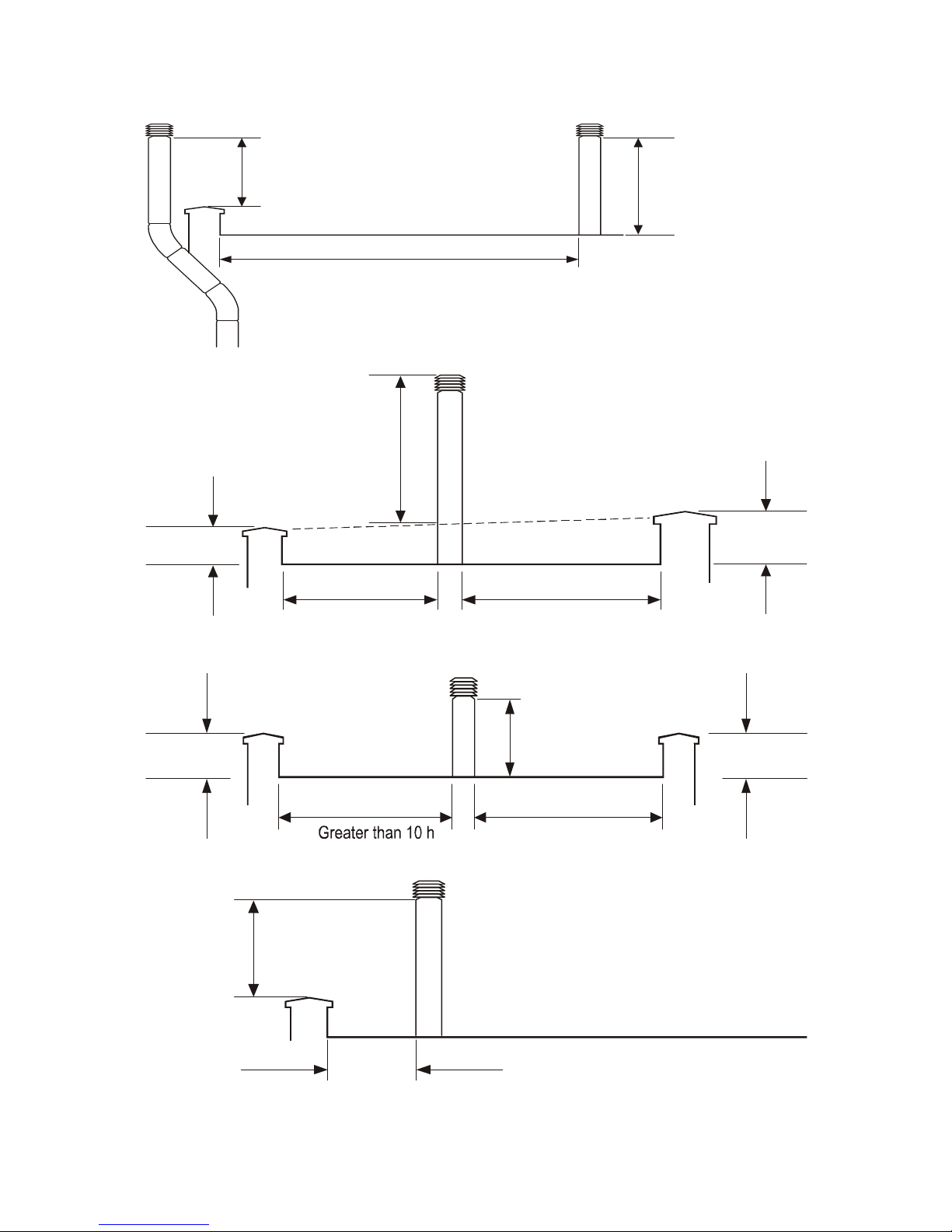
Not less than
600mm
Not less than
600mm
Greater than 1500mm
Parapet
Not less than
600mm
Less than 10 h
Greater than 1500mm
H
1
H
2
2
Less than 10 h
1
Flat roof with parapet
Flat roof envelope method
Structure
Not less than
250mm
2
Greater than 10 h
1
H
1
H
2
Structure
Flat roof where the flue height is more than 10 Heights (H) away from all structures
Structure
Not less than
600mm
Less than 1500mm
Flat roof with flue close to parapet
Page 16
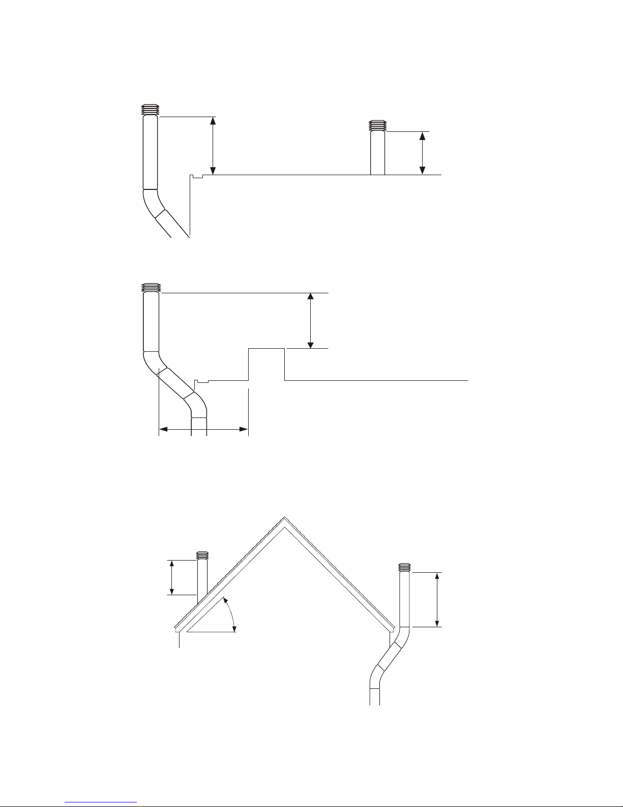
Not less than
600mm
Less than
1500m
m
Structure
Flat roof with structure close to flue outlet
Pitched roof not greater than 45°
Not less than
600mm
Not greater than
45
°
Not less tha
n
600mm
Not less than
600mm
Not less than
250mm
Flat roof with no parapet
Page 17

2.7 Flue Installation
An integral flue spigot is fitted to all Cabinet
Heaters thereby allowing the flue to connect
directly to the heater. The design of the flue
must ensure that it can be disconnected to
allow for cleaning and servicing, furthermore,
all of the flue section joint sockets must face
upwards, and the seal between the sections
achieved through mechanical joints or
through the use of approved caulking string
and grout. It is strongly advised that BS 5854
and BS 5440 parts 1 and 2 are referred to,
see also figs 2-12.
Where condensation is likely to be a problem
provision should be made preferably at the
design stage (see section 2.5).
3.0 Installation
It is strongly advised that the installer reads
Section 2 and Section 3 of this manual prior
to starting any installation work. It is a
requirement that only qualified and
competent personnel may undertake
installation, commissioning, and servicing.
Warning
Always ensure that the appropriate personal
protective equipment is used.
3.1 Packaging/siting
The heater will usually be supplied wrapped
in polythene, non assembled parts will be
supplied separately. Prior to installation, the
assembly of the heater should be completed,
it is advisable that this is undertaken in the
area where the heater is scheduled to be
sited.
Caution
It is strongly advised that when positioning
the heater the lifting eyes are used, thereby
reducing the risk of inadvertent damage
being occasioned to the heater.
3.2 Flooring
The heater must be installed on a level non
combustible surface capable of supporting
the weight of the heater and any ancillary
equipment.
3.3 Minimum clearances
The following minimum clearances (in
millimeters) must be observed when
installing the heater.
3.4 Assembly
The following sub-assembly parts should be
assembled to allow installation to continue.
(a) Vertical Nozzled Models
For free blowing applications it will be
necessary to complete the final assembly
before continuing with the installation. The
bonnet top with nozzle spigots should be
attached to the heater and secured. The
nozzles should then be pushed home on the
spigots and positioned to provide the desired
airflow.
Ensure louvres are adjusted outwards
and ensure blades are not resonating
The nozzles should be securely fixed in their
desired position on completion of
commissioning.
(b) Horizontal Nozzled Models
Remove packaging and secure the 90
o
Duct
Outlet to the outlet on the heater using the
bolts supplied.
Secure the nozzle spigot plate to the duct
outlet using the bolts and prevailing torque
nuts provided. Fit the securing brackets to
each of the outlet nozzles, and lift the
complete heater assembly and position on
the pre-sited purpose built supports. Finish
off the assembly by fitting and securing the
outlet nozzles to the spigots by way of
previously fitted brackets.
Model Size Front Rear Lhs Rhs
100 -150 500 700 150 150
200 - 300 500 1,000 150 150
400 - 500 600 1,200 150 150
600 600 1,500 150 150
700 900 1,500 150 150
800 - 1000 900 2,000 400 400
1200-1300 900 2,000 500 500
Page 18

3.5 Gas Installation/Connection
Service pipework must terminate at an
approved gas cock, and be adjacent to the
position of the heater.
The connection to the heater can be made
by way of either an approved flexible
coupling, or rigid connection. Threaded
connections must comply with ISO288/1 or
ISO 7/1, further information concerning the
accepted practice in European countries is
detailed in the June 1995 version of prEN
1020 annex A7 The diameter of the pipework
from the cock to the burner connection must
not be less than the diameter of the burner
connection inlet. (see section 8 )
The installation must be purged and tested
for soundness prior to commissioning.
Always ensure that the appropriate personal
protective equipment is used.
3.6 Electrical Installation/Connection
Benson cabinet heaters are available either
for 415V 50Hz 3PH or 230V 50Hz 1PH
supplies depending upon the model
specified.
It is recommended that reference is made to
the wiring diagrams contained within section
7 of this manual prior to installation or
connection to the supply.
The electrical supply must be as specified
and suitable for the heater, and must be run
within conduit to a point adjacent to the
heater, and be terminated to provide an
isolation point that will prevent remote or
inadvertent activation. Cables, conduit, and
fittings that are used to make the connection
between the isolator and the heater must
conform to the appropriate IEE regulations.
All heaters are supplied fused and pre-wired,
all must be earthed.
Final connections for any additional external
controls must be completed on site, and
must be carried out according to IEE
regulations. Separate user information is
provided for the time control unit and the
burner, and forms part of the product
information pack which accompanies every
heater when despatched.
Warning
Always isolate from mains electrical supply
before commencing work on the heater.
Always ensure that the appropriate personal
protective equipment is used.
3.7 Air Distribution Installation
The materials selected must be of low heat
capacity, and it is preferable that all warm air
ductwork is thermally insulated.
Where ducting may be subject to
deterioration from exposure to moisture or
high humidity material selection and
insulation are prime considerations.
Joints and seams must be airtight and
fastened securely and designed to remain
so, even when operating at high
temperatures. Adequate support must be
designed into the layout of the ductwork to
ensure that the integrity of the seams and
joints is maintained.
The support must be independent and
separate from the heater and the ducting, to
allow for free movement during expansion
and contraction.
Where ducting passes through walls or
partitions sufficient clearance must be left,
irrespective of any fire stop requirement, to
allow for expansion and contraction Failure
to adhere to these latter two points can result
in the generation and transmission of excess
noise.
Where ducting is installed in concrete
flooring a permanent membrane must be
used to isolate the ducting from the corrosive
effect of the alkaline salts within the
concrete. Care should be taken to ensure
that soft insulation material does not become
compressed and thereby lose its
effectiveness.
3.8 Warm Air Registers
In order that vertical temperature gradients
are minimal thereby providing a more even
heat distribution, it is preferable to install
warm air registers at low wall levels or at
floor level, with the size, number, and
position commensurate with the requirement
of the application.
Page 19

To minimise noise levels the registers should
be set away from corners, additionally, a good
seal between the register frame and the wall
is important, particularly on high level
positions, if unsightly staining through warm
air/ particulate deposition is to be avoided.
3.9 Heater Control Installation
Warning
Isolate heater from mains before undertaking
any electrical work.
Unless specified all Cabinet Heaters from 100
to 1300 are manufactured and supplied with a
CP2 Control as standard .
The following controls fitted and pre-wired
(a) On/standby switch
(b) Ventilation/heat switch (summer/winter
switch)
(c) Manual/automatic switch
(d) Thermostat
(e) Time clock
(f) Frost stat
A CP4 Controller is available as an option
All of the above controls are located on a
removable panel which when separated from
the heater can be re-positioned so as to offer
a remote facility.
However, to facilitate this, it is necessary to
order and fit an electrical panel cover and
front panel blanking plate to the heater in
place of the control unit.
The controls for Horizontal Cabinets are
supplied as remote option.
4.0 Commissioning
It is a requirement that only suitably
qualified and competent personnel are
allowed to undertake the
commissioning of the heater.
It is also strongly recommended that prior to
commissioning the engineer familiarises
himself with; the information contained within
the information pack that accompanies the
heater, the heater itself, and with the specific
requirements of the installation /application.
Warning
All Cabinet Heaters undergo a rigorous test
programme prior to being despatched, whilst
such a programme does involve precommissioning and setting up the heater to
operate efficiently and well within its designed
operational limits, this does not mean that on
site commissioning is less important than
might otherwise be the case.
Note
It is strongly recommended that equipment
used for the sampling and analysis of flue
gases is accurate to within +/- 0.1% and
maintained so that it is regularly calibrated.
4.1 Commissioning - Pretest
Check to ensure electrical safety, and inspect
and check the installation, testing for leaks.
(a) Ensure that the electrical supply is turned
off.
(b) Ensure that the gas supply is turned off.
(c) Check that all panels and fasteners are
secure and in place.
(d) Check that the heater is installed so that it
is square and that the support is adequate.
(e) Ensure that warm air delivery outlets are
open and that ducting is adequately
supported.
(f) Ensure that if filter assemblies are fitted
that they are secure and correctly located.
(g) Check that air inlets are clear and that
return air paths are adequate.
(h) Ensure that the flue is secure, adequately
supported, and that the various joints are
properly sealed.
(i) Check that condensate trap and drain
facilities are adequate.
(j) Check that there is provision for flue gas
sampling and that this sample point can be
plugged and sealed after commissioning.
Page 20

(k) Check that fan and limit stat settings have
not been disturbed and are as follows
100/700 800/1000
Range
Fan on - 60oC Fan on - 50
o
C
Overheat limit -100oC Overheat limit -100
o
C
Fan off - 30oC Fan off - 30
o
C
Also check that the white button (automatic)
is pulled outward and that the red button
(reset) is pushed inwards to the reset
position. See fig 15.
(l) Remove lower panel and check motor and
fan drive system for integrity of joints, check
pulley alignment, fan rotation, and belt
tension (see section 5.2 and figs 17 and 18).
(m) Ensure that the burner is securely
attached to the heater.
(n) Test for electrical earth continuity
between the heater, oil pipe work, and mains
supply.
ANALOGUE TYPE
(o) Turn on main electrical supply, select the
following switch settings
On/Standby - Standby
Heat/Ventilation - Ventilation
Manual/Automatic - Manual
OPTIMISED TYPE
Press FAN /Enter
The fan will start enabling fan direction etc to
be verified. Reset on/standby switch to
standby position
(p) Turn mains electrical supply to off,
replace and secure lower louvered panel
covering fan and motor assembly.
(q) Set room thermostat and time clock to
'demand' positions.
4.2 Commissioning - Ignition
Warning
Do not proceed with commissioning unless
all the criteria detailed within sections 4.0
and 4.1 have been satisfied.
(a) Ensure that the electrical supply is turned
off.
(b) Ensure that the gas supply is turned off.
(c) Select the following switch settings on the
heater
ANALOGUE TYPE
On/Standby - Standby
Heat/Ventilation - Heat
Manual/Automatic - Automatic
(d) Turn on main electrical supply.
(e) Select 'on' position for heater on/standby
switch.
OPTIMISED TYPE
(f) Prog 0000 Enter 1TEMP key in an
operating temp and Enter
Press RUN 3 times to return to main screen
Press OVER button Select 1 OVERIDE then
select 1 and key in 01 hour override this will
allow enough time to commission the heater
safely
(g) Check for the following burner sequence
Interval Operand
1 <5s Combustion air damper actuated,
burner fan motor initiates purge
cycle...
2 <40s Pilot valve opens ignition
transformer provides spark for
pilot ignition...
-------- E I T H E R --------
3 >40s Ignition failure caused by gas
starvation resulting in burner lock out/shut-down...
(g) Clear burner lockout using burner reset
function.
(h) Set heater on/standby switch to standby
position
(i) Open gas supply cocks Repeat steps 4.1
q, and 4.2 c,e,f.
----------- O R ----------
3 >40s Pilot ignition... Burner ignition...
4 <60s Burner ignition cycle complete
Page 21

Note
It is strongly recommended that the separate
manual concerning the operational details of
the burner supplied with the heater as part of
the information package is studied prior to
commissioning.
Time intervals within the ignition sequence
will vary slightly from one model to another.
Warning
If burner ignition is not satisfactorily
accomplished, commissioning must not
proceed until the reason or fault has been
identified and rectified, if necessary by
reference to the separate burner information
or to section 6 of this manual.
( j ) Repeat steps 4.2 c,a,
(k) Re-check all connections and joints for
gas soundness using an approved leak
detection fluid.
(l) Remove burner cover and attach
manometers to check burner pressure
settings.
(m) Repeat steps 4.2 d,e,f, allowing the
heater to reach thermal equilibrium.
(n) Check burner pressure settings are in line
with the data as per section 8.1 (if
adjustment is necessary refer to separate
burner information within section B)
Note (i)
The figures quoted in section B are
independent test figures based upon zero
flue resistance.
On completion mark the gas valve
adjustment screw with paint/sealant to
prevent tampering with valve
(o) Adjust room thermostat to its highest
setting, and allow the heater to continue to
fire.
(p) Gradually reduce the temperature setting
on the room thermostat until the burner shuts
down, (@ < ambient) and then gradually
increase the temperature setting on the
thermostat until heat is called for,
(@ > ambient) and the burner automatically
re-fires.
(q) Re-set time clock to a minimum off
period, checking that the burner shuts down,
and then automatically re-lights once the
minimum off period has elapsed (Separate
information on the time clock is contained
within the information package supplied with
the heater).
(r) Check fan and limit stat by depressing
and holding in the fan motor overload re-set
button, located on the heater electrical panel.
The time between the fan stopping and
burner shut down should be noted, once the
burner has shut down the overload on the
motor should be released.
If the time interval between fan stop and
burner shut down is greater than 90 seconds
further checks should be made.
These are as follows:
(i) Check settings on fan and limit stat are
correct,for heater type ie, fan on 60
o
C, fan
off 30
o
C, limit 100oC.
On completion delete any override settings
on optimised control and return temperature
settings to customer requirements
(ii) Check that the position of the unit is
correct, ie, equi-distant between heat
exchanger body and heat shield panel.
(iii) Check integrity of unit, ensuring that
neither the bi-metallic strip nor its casing is
damaged.
(s) Undertake flue gas analysis using
approved and calibrated analysing
equipment recording data on the
commissioning card, ie, CO, CO
2
, net and
gross flue temperatures. Record mains gas,
and burner head pressure, ambient
temperature, barometric pressure, and
complete percentage efficiency calculation
using the formula detailed in section 8.
Note (ii)
The burner air and gas pressure settings
should be only very finely adjusted to
achieve a CO
2
reading of 9.3% (+/- 0.1%).
Note (iii)
The net efficiency must not be lower than
79% for heaters fitted with a modulating or
hi / lo burner.
In other cases the net efficiency level must
not be lower than 84%
Page 22

Note (iv)
All Cabinet Heaters are test fired and precommissioned as part of the manufacturing
process, if however, during on site
commissioning the data are found to be not
in accordance with the manufacturers data,
then the following action is recommended.
* Re-check all readings and calculations.
* Adjust burner as per manufacturers
instructions.
* Consult Benson Heating Technical
Department.
(t) Complete commissioning card and
provide operating instructions for the user,
high-light the fact that the manufacturer
recommends that in the interests of safety
and efficiency the heater is serviced on a
regular basis only by qualified and competent
persons.
The completed commissioning card must be
returned to Benson Heating Service
Department immediately after the
satisfactory completion of commissioning,
failure to do so can invalidate any
subsequent warranty claim.
(u) Set all controls to the requirements of the
user
.
4.3 Commissioning - air delivery
system
On free blowing applications the integrity of
the fastenings on the heater top and outlet
nozzles must be checked .
Final adjustment for the direction of the air
flow from the nozzle hoods should be
made.Ensure louvres are adjusted
outwards and ensure blades are not
resonating
and the hoods should be secured in the
required position by drilling through the two
holes provided in the hood outer ring and
fastened in place using self tapping screws .
Caution
On ducted applications it is necessary that
the system is balanced in order to optimise
the efficiency of the heater and the air
distribution and delivery system. Failure to
balance the system can result in fan motor
overloading and premature component
failure, it can also result in an inefficient
heating/ventilation system.
(a) Check that the amount of fan produced
air volume is in accordance with the heater
specification, if the volume is too great the
fan can be overloaded. Ensure that the
running current is as per that stated on the
heater data plate. Alternatively, the static
pressure should be measured at the start of
the ductwork to confirm that it is within the
permissible tolerance.
(b) If the current drawn is greater than the
stated running current, in most probability
this will be caused by insufficient static
pressure within the ductwork, in which case
system resistance should be increased
through the introduction of a damper placed
as close to the start of the ductwork as
possible, thereby resulting in a reduction in
drawn current. The damper should be
adjusted until the current is in accordance
with that stated on the data plate.
(c) If the current drawn is too low the duct
outlet grilles will require opening to reduce
static pressure and increase air volume, if
this is not the case overheat cut outs can be
caused.
The Fan Belts must be rechecked on
completion of commissioning ensuring
that the tension is correct and the pulleys
are in alignment
4.4 Commissioning - hand over
(a) Upon full and satisfactory completion of
commissioning, a record of commissioning
information
(contact, date, etc) should be left with the
heater, a copy of which must also be
forwarded to Benson Heating Service Dept.
(b) The commissioning engineer must ensure
that the user is familiar with the safe and
efficient use of the heater, detailing the
function of all controls and main components.
(c) The user should be made aware of the
following in particular
(i) Lighting, shutdown, and operational
information.
(ii) Safety features, data plate, and labeling.
(iii) The requirement for regular inspection especially if the heater is within a more
demanding environment - and the need for
Page 23

regular servicing carried out by competent
and qualified persons.
Caution
After approximately 100 hours of running, the
tension of the fan belts must be checked to
ensure that they are correct and that they
have not stretched. See section 5.2 for
further instructions
5.0 Servicing
Warning
Servicing must be carried out on a regular
basis, the maximum interval between
services being 1 year. It is a requirement that
only suitably qualified and competent
persons are allowed to undertake servicing.
Before any maintenance or servicing work is
carried out the heater must be shut down
and allowed to cool, and have the gas and
electric supplies to it turned off at the gas
cock and isolator respectively.
Caution
Certain component parts are factory sealed
and are designed so as to be tamper proof.
Usually such items do not require servicing,
and therefore should not be tampered with.
Failure to comply with this can invalidate any
warranty, and can also lead to premature
failure.
The following parts fall within this category:
room thermostat, time clock, frost thermostat,
sequential controller, and fan and motor.
Additionally, the fan and limit stat has been
factory set, and must not be re-set without
formal consent from the manufacturer.
Reference should be made to the separate
information covering the operational details
of the burner and timer.
Only approved spare/replacement parts
can be fitted, failure to comply with this
can compromise the safe and efficient
running of the heater, and can also
invalidate any warranty claim.
5.1 Planned Servicing
In order to maintain the efficient operation of
the heater it is recommended that the
following planned servicing and preventative
maintenance programme is adopted by the
user.
Quarterly Inspection
(a) Visual inspection of the burner
(b) Clean and check ionisation probes
(c) Check overheat safety is operational
Bi-Annual Inspection
(a) As per quarterly inspection, plus...
(b) Combustion check
Annual Inspection
(a) As per half year inspection, plus.
(b) Heat exchanger and cleaning
(c) Electrical connections
(d) Main fan motor
(e) Main fan assembly
(f) Pulleys
(g) Fan belts
(h) Gas supply
(i) Burner
(j) Air delivery system
(k) Flue
(l) Report
5.2 Servicing Procedure - Major
Component Parts
Flue
A visual inspection should be carried out to
ensure that the flue remains adequately
supported, both internally as well as
externally, and that the various joints are
effectively sealed.
Inspection covers, where fitted, should be
removed and the flue checked to see
whether cleaning is required If inspection
covers are not fitted the flue gas exit duct
and flue spigot will provide not only an
indication of the cleanliness of the flue, but
will also enable access for cleaning. The
presence of the flue terminal should be
checked. If a condensate trap and drain
facility is fitted this should be checked to
ensure that it continues to function correctly,
and the drainage of condensates is not
impaired.
Main Fan Motor
Remove access panel, dust and other
foreign matter should be cleaned by blowing
over with compressed air and through the
use of a soft bristle brush and cloth. Solvent
Page 24
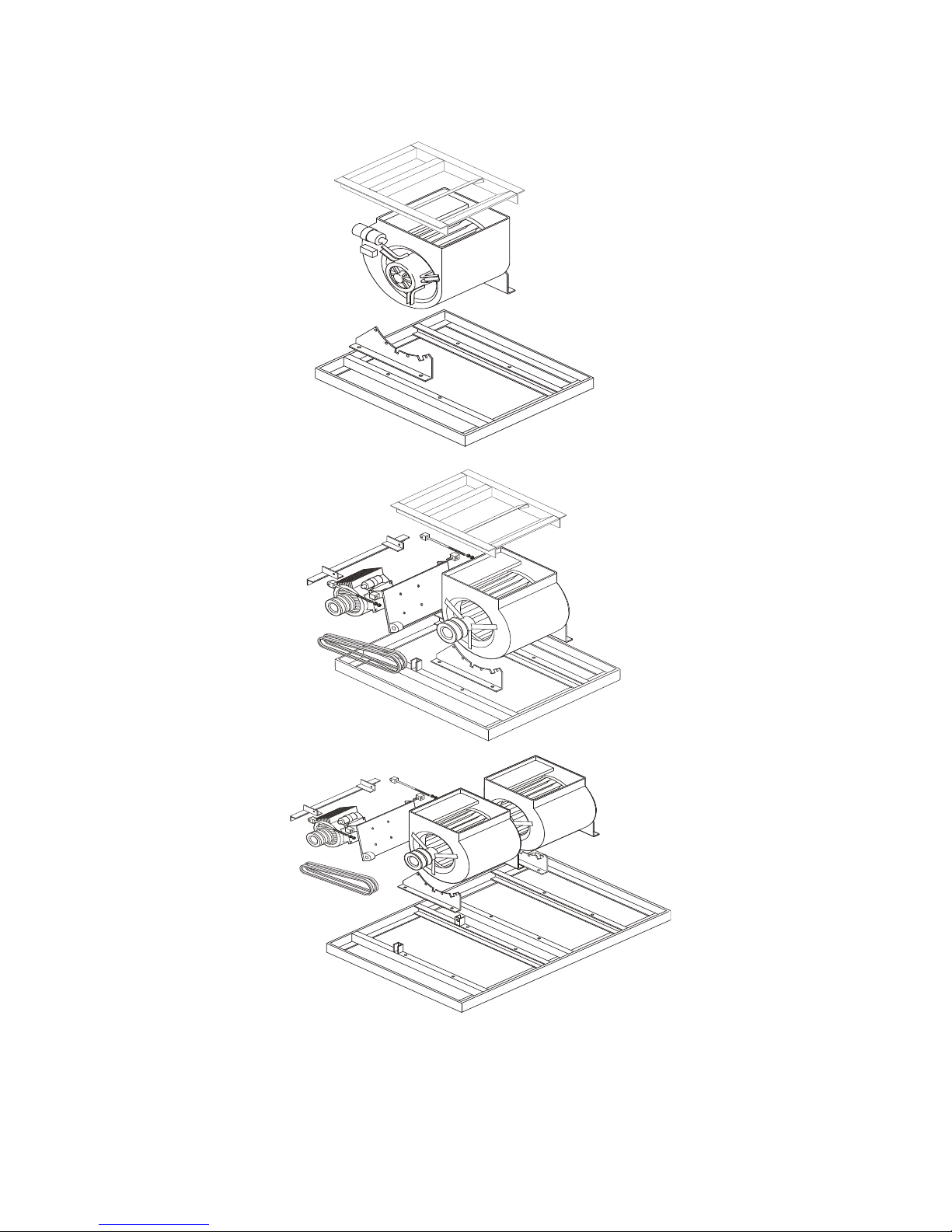
Motorised Fan
Assembly
100-300
Fan and Motor
Assembly
400-700
Fan and Motor
Assembly
800-1300
Page 25
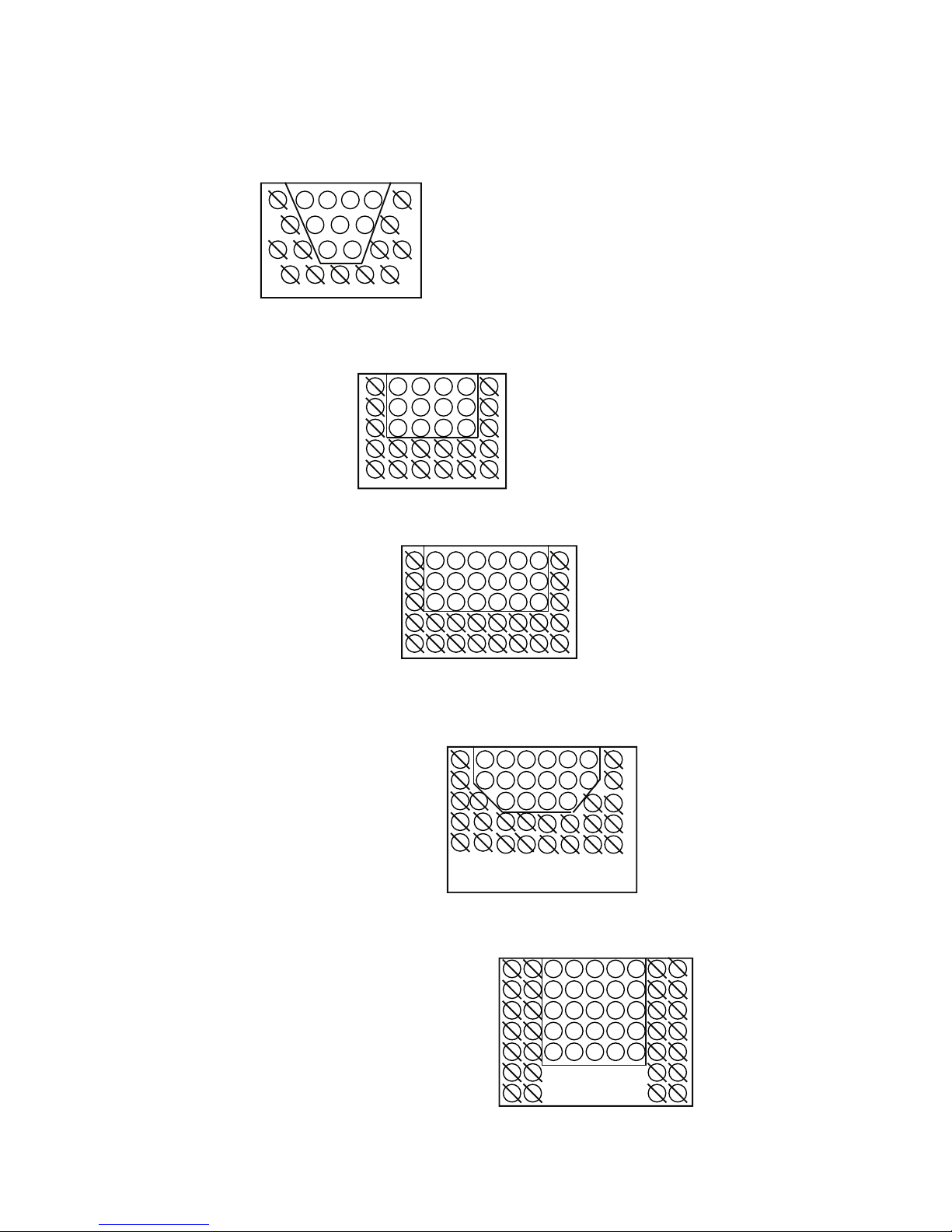
Turbulator Positions in Heat Exchanger 200-250-300 Gas Cabinets 13 off
Turbulator Positions in Heat Exchanger 400-500 Gas Cabinets 18 off
Turbulator Positions in Heat Exchanger 600-700 Gas Cabinets 22 off
Turbulator Positions in Heat Exchanger 800-1000 Gas Cabinets 24 off
Turbulator Positions in Heat Exchanger 1200-1300 Gas Cabinets 28 off
Page 26

wipes may be used to remove heavy soiling
from the motor casing.
Traces of surplus lubricants spreading from
the bearings should also be cleaned away.
Where motors are fitted with grease nipples
bearings should be lubricated with the
correct grade of lubricant. motors which do
not have grease nipples feature sealed
bearings which are lubricated during
manufacture for their life.
The electrical connections should be
checked as follows.
The cover to the terminal box should be
removed by undoing the screws which
secure it.
Check connections for signs of corrosion,
tightness, and ensure that there are no stray
strands which could form a short circuit.
Clean, tighten, and replace as necessary.
Replace cover and secure
Main Fan
Remove dust and other foreign matter by
blowing off with compressed air or through
the use of a soft bristle brush.
Check that the bearings do not show signs of
excessive wear.
It should be noted that these bearings do not
require lubricating.
If the bearings require replacing the following
procedure should be followed.
(a) Remove belt(s).
(b) Loosen setscrew on eccentric collar and
tap collar in the opposite direction to fan
rotation.
(c) Remove collar and bearing.
(d) Check shaft for alignment and
straightness.
(e) Locate the bearing in its seat and place
on the shaft with the cam facing outwards.
(f) Fit the eccentric collar and engage the
cams.
(g) Tighten initially by rotating, and then by
tapping in the direction of the fan rotation.
(h) Replace fasteners and secure.
(i) Turn by hand to ensure free fan rotation.
Pulleys
Check pulleys for alignment using a straight
edge, if necessary reposition either or both of
the pulleys and the fan motor. Check for
excessive wear within the root and sides of
the grooves, and check for any other signs of
wear or damage, if necessary replace the
pulley as follows.
(a) Release tension on belts and remove.
(b) Release the taper locks by slackening the
securing screws by several complete turns.
(c) Fully remove one screw from the taper
lock, and having oiled it, insert into the
threaded jacking point.
(d) Tighten screw until the taperlock is free.
(e) Remove taperlock and pulley.
(f) Fit taperlock in new pulley, and
provisionally position on the shaft.
(g) Remove the screw from the jacking point,
and tighten both screws in their clamping
points until the pulley can just be moved on
the shaft by hand.
(h) Align pulleys using a straight edge, and
by gradual alternate tightening of the screws
clamp in position.
(i) Refit belts and check for the correct
amount of tension.
Fan Belts
Check belts for signs of wear.
Frayed or split belts must be replaced using
belts with a common batch code.
Belt tension must be checked, and if on
multi-belt units it is found that one belt
contains more slack than its accompanying
belts, then all the belts on the unit must be
replaced, again using a common batch code.
Replacement and tensioning is carried out as
follows.
Note
The maximum displacement at the mid point
of the top edge of the belt must not be
greater than 16mm per metre of span, when
a force of 3kg is applied in a plane
perpendicular to the belt.
(a) Loosen fan motor securing bolts on
chassis.
(b) Loosen fan motor slide adjustment bolt.
(c) Slide fan towards fan to slacken belts.
(d) Replace belts, pull fan motor away from
fan until belts are tight.
(e) Tighten adjustment bolt to hold motor.
(f) Tighten fan securing bolts ensuring that
the fan is square and the pulleys aligned.
(g) Check belt tension, making final
adjustments as necessary.
(h) Tighten and clamp fasteners to hold fan
motor in position.
Page 27

Heat Exchanger
The heat exchanger requires a visual
inspection at least once per year, this should
be accompanied by cleaning.
It is recommended that a flue brush and
vacuum cleaner are used to facilitate this.
Access to the heat exchanger is gained
through the removal of the rear upper panel
and heat shield.
Servicing and cleaning should be performed
as follows.
(a) Remove brass nuts and cover from heat
exchanger end assembly to expose heat
exchanger tubes.
(b) Remove any accumulated deposits from
the tubes by pushing through the full length
with a flue brush.
(c) The flue brush should be withdrawn so as
to pull any deposits back into the bottom of
the flue box where they can then be removed
by using a vacuum cleaner.
(d) Particular attention should be paid to the
upper internal surfaces of the tubes, where
through convection heavier deposition is
likely to occur.
(e) Any deposits which may have
accumulated within the combustion chamber
can be removed with a vacuum cleaner once
the burner is removed.
Note
It is most important that a build up of
deposits is not allowed to occur as this can
have an adverse effect upon the efficiency of
the heater and reduce the life of the heat
exchanger.
(f) The heat exchanger and combustion
chamber should be visually inspected for
signs of splits, cracks, and distortion
(g) All gaskets should be checked to ensure
that they continue to provide a gas tight seal,
if there is an element of doubt then they
should be replaced.
If the condition of the heat exchanger gives
cause for concern the Service Department at
Benson Heating should be advised pending
a more detailed examination.
Electrical Supply
All connections must be checked to ensure
that they are secure, and free from corrosion.
Terminals and connections should also be
checked to ensure that no stray strands are
bridging terminals.
Electrical continuity should also be checked.
Gas Supply
The gas supply pipework, and fittings should
all be inspected to ensure that they are free
from corrosion, and to ensure that where
brackets have been fitted these remain
secure and offer adequate support.
The system should be soundness tested in
accordance with Institute of Gas Engineers
recommendations detailed in
UP-1 and UP-2.
Burner
Service requirements for the burner fitted to
the cabinet heater are covered in the
separate manual prepared by the burner
manufacturer.
Note
It is most important that the burner is
serviced regularly and in accordance with the
manufacturers instructions.
Air Delivery System
A visual inspection should be undertaken to
ensure that the air delivery system is in good
order, and that it remains adequately
supported and that the various joints are
effectively sealed.
Report
A full and detailed service report should be
prepared, it is advised that the report is not
completed until the heater has been recommissioned, where upon the completed
report can then be run through with the user.
5.3 Service Re-commissioning
The heater should be re-commissioned as
follows, as per section 4.1 through to section
4.4 inclusive.
This must be regarded as a necessary part
of the heater service by the servicing
engineer.
Page 28
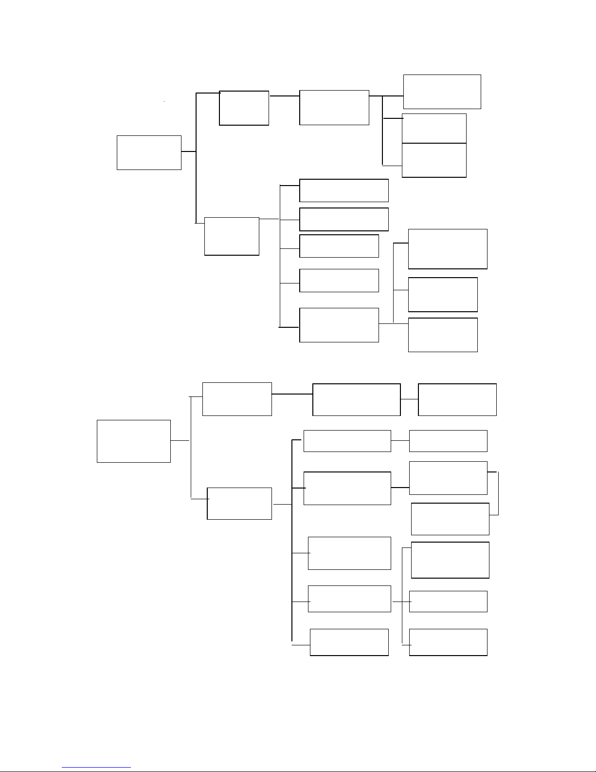
No
Power
No
Dema nd
Check
Isolator
Check On/Off
Switch
Check
Fuses
Check Thermostat
Burner fails
to Run
Check Timer
Check Overheat
Check Voltage
Check Control
Box and Burner
Check for
Lockout
Check Air
Pressure Switch
Check Burner
Motor
Check Flame
Probe
Fan Starts but
Burner
g
oes to
Lockout
Check Gas
Supply
Ign ition
Failure
Ensure G as C ock is
Open
Ensure start Gas
Valve Opens
Air in Gas Feed
Faulty Air Pressure
Switch
Purge Air
Check as per
Burner Manual
Faulty Electrode
Check Gap
Check Insulation
Fa ulty Ign itio n
Transformer
Check Control
Box
Check HT Lead
and Connector
Control Box Fault
Page 29
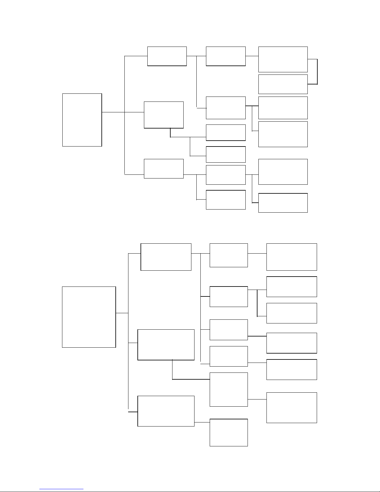
Burner
lights on
start gas
but fails to
establish
main
flame
Check Gas
supply
Excess Air Check that flue
Gas CO is as
advised
A
djust damper
to suit
Check Inlet
Gas Pressure
Check
Flame
Probe
Low Gas
Pressure
Check Main
Burner Gas
Pressure
Signal
Position
Check
Controls
Check
Burner
Check
Control
Check Low
Flame Switch
is On
Check Slow
Acting Valve
Burner starts
but excess
temperature
shuts down the
burner on
overheat
lockout
Insufficient air
passing over
Heat Exchanger
Check air to
inlet is no t
restricted
Resistance
too hig h
Remove
Obstruction
Clean Filters
Check Outlet
Grilles a re O p e n
Check Nozzles
are Open
High Return (inlet )
Air Temperature
Faulty or
incorrectly set Fan
Limit Control
Fan Belt
Slipp in g
Impe llo r
Slipp in g
Check for
wa rm air
short circuit
to Ai r Inlet
Reset Fan
Limit
Control
Adjust and or
replace Belts
Tighten
Cou p lin g s
Reset Nozzles
away from
adjac e nt walls
Page 30
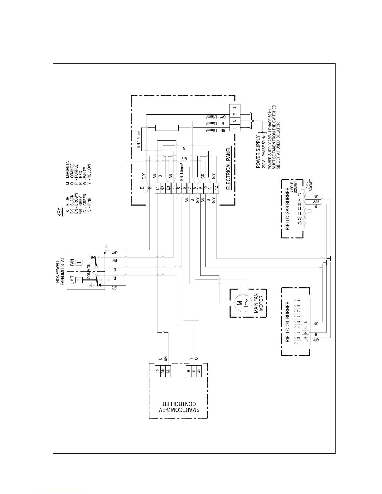
Wiring Diagram 20-45-419
100-300 ON/OFF Riello Gas or Oil Fired Burner SC³-FM 230/50/1ph
10A MCB
Page 31
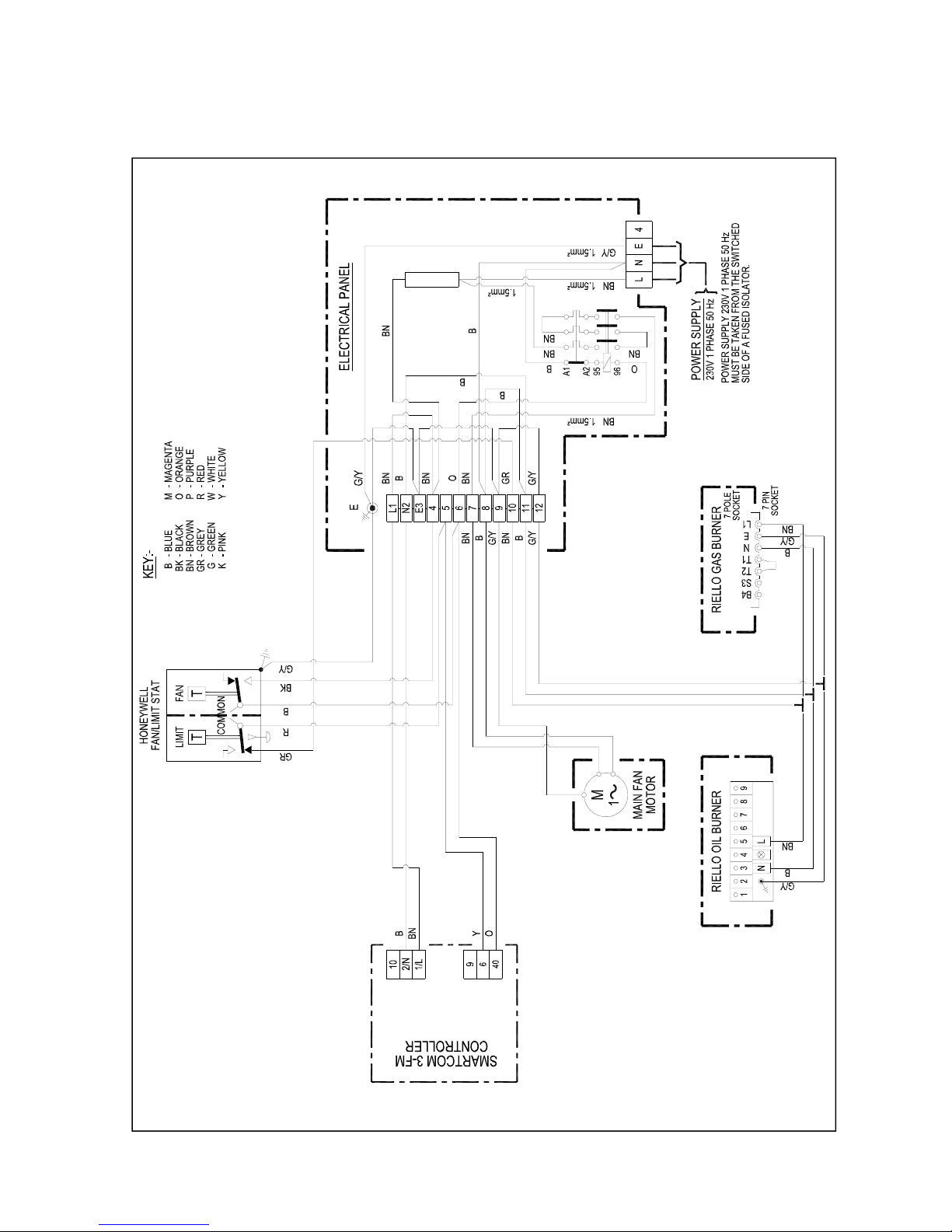
Wiring Diagram 20-45-421
400-500 ON/OFF Riello Gas or Oil Fired Burner SC³-FM 230/50/1ph
6A MCB
Page 32
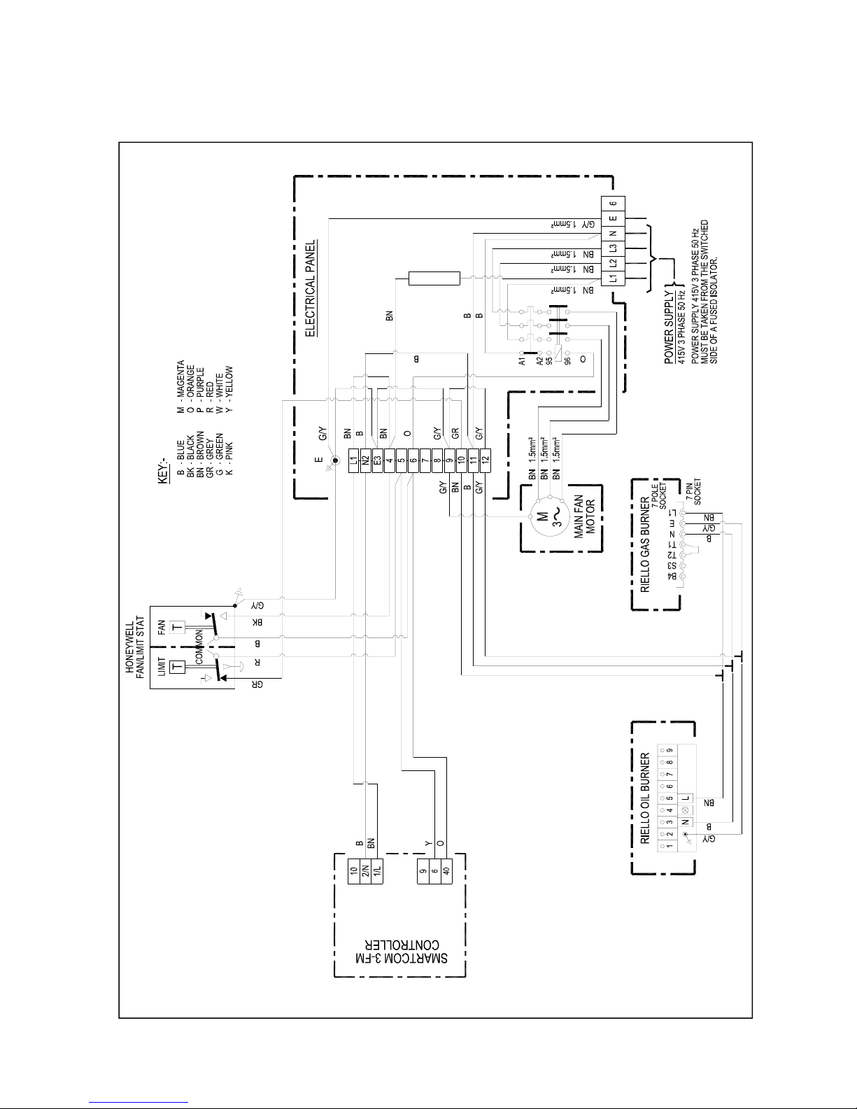
Wiring Diagram 20-45-423
200-1000 ON/OFF Riello Gas or Oil Fired Burner SC³-FM 415/50/3ph
6A MCB
Page 33
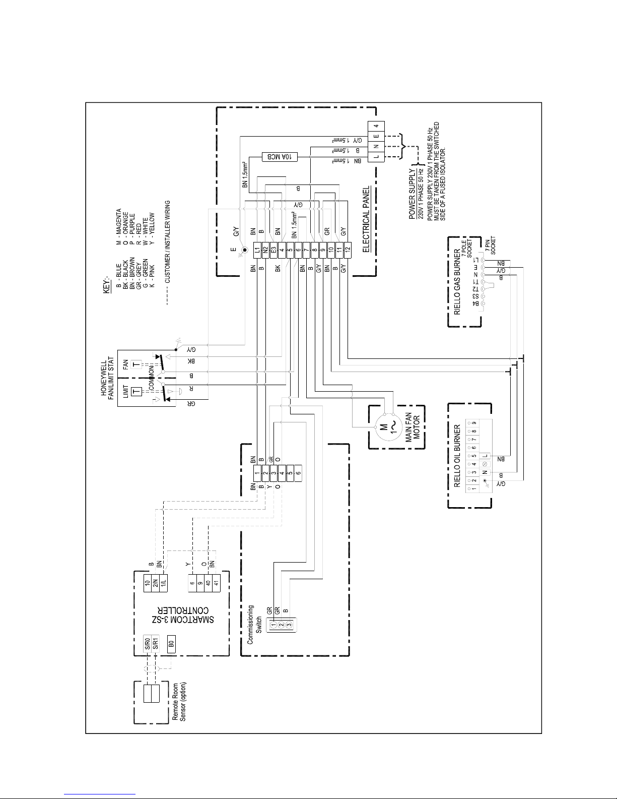
Wiring Diagram 20-45-420
100-300 ON/OFF Riello Gas or Oil Fired Burner Remote SC³-SZ 230/50/1ph
Page 34
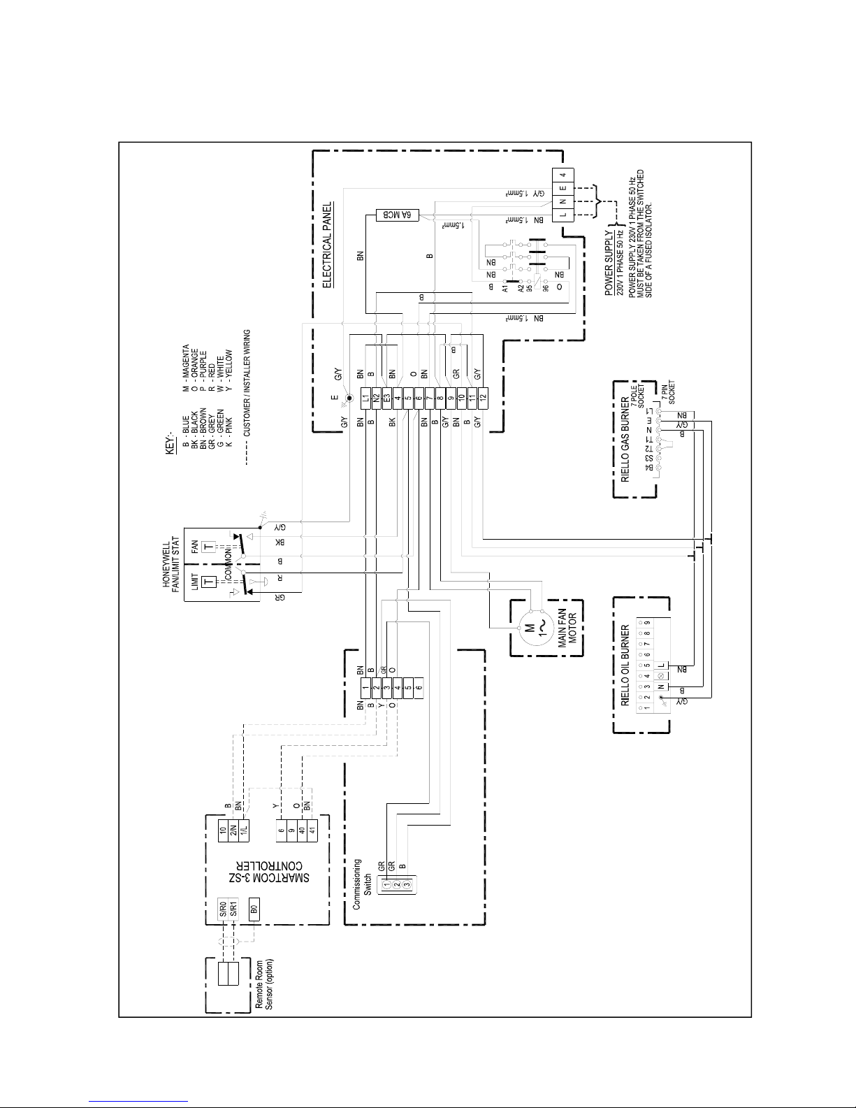
Wiring Diagram 20-45-422
400-500 ON/OFF Riello Gas or Oil Fired Burner Remote SC³-SZ 230/50/1ph
Page 35
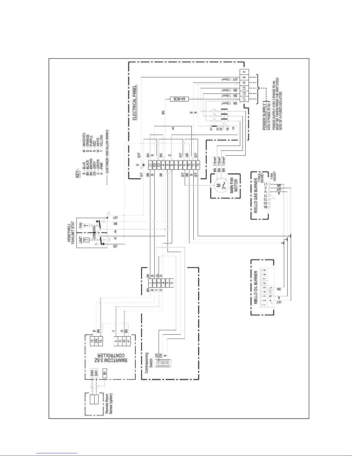
Wiring Diagram 20-45-424
200-1000 ON/OFF Riello Gas or Oil Fired Burner Remote SC³-SZ 415/50/3ph
Page 36
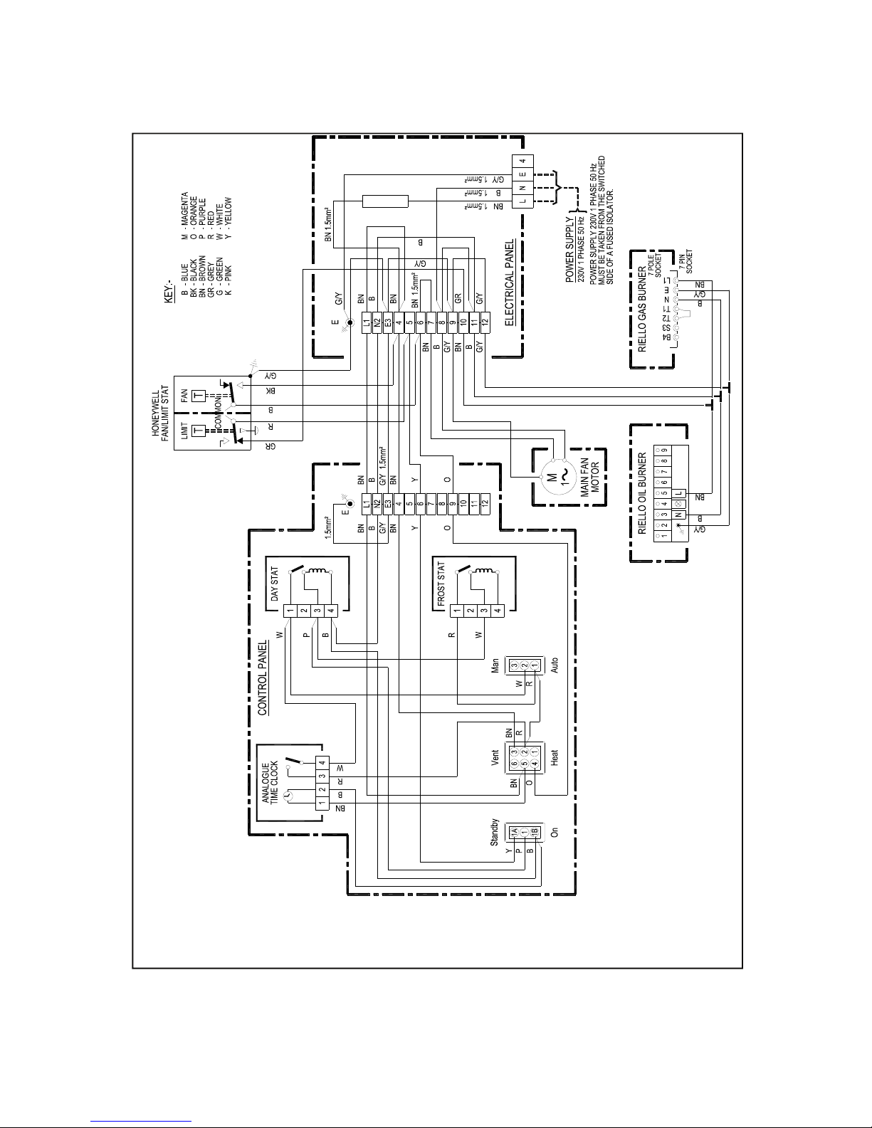
Wiring Diagram 20-45-181
100-300 ON/OFF Riello Gas or Oil Fired Burner Remote CP2 230/50/1ph
10A MCB
Page 37
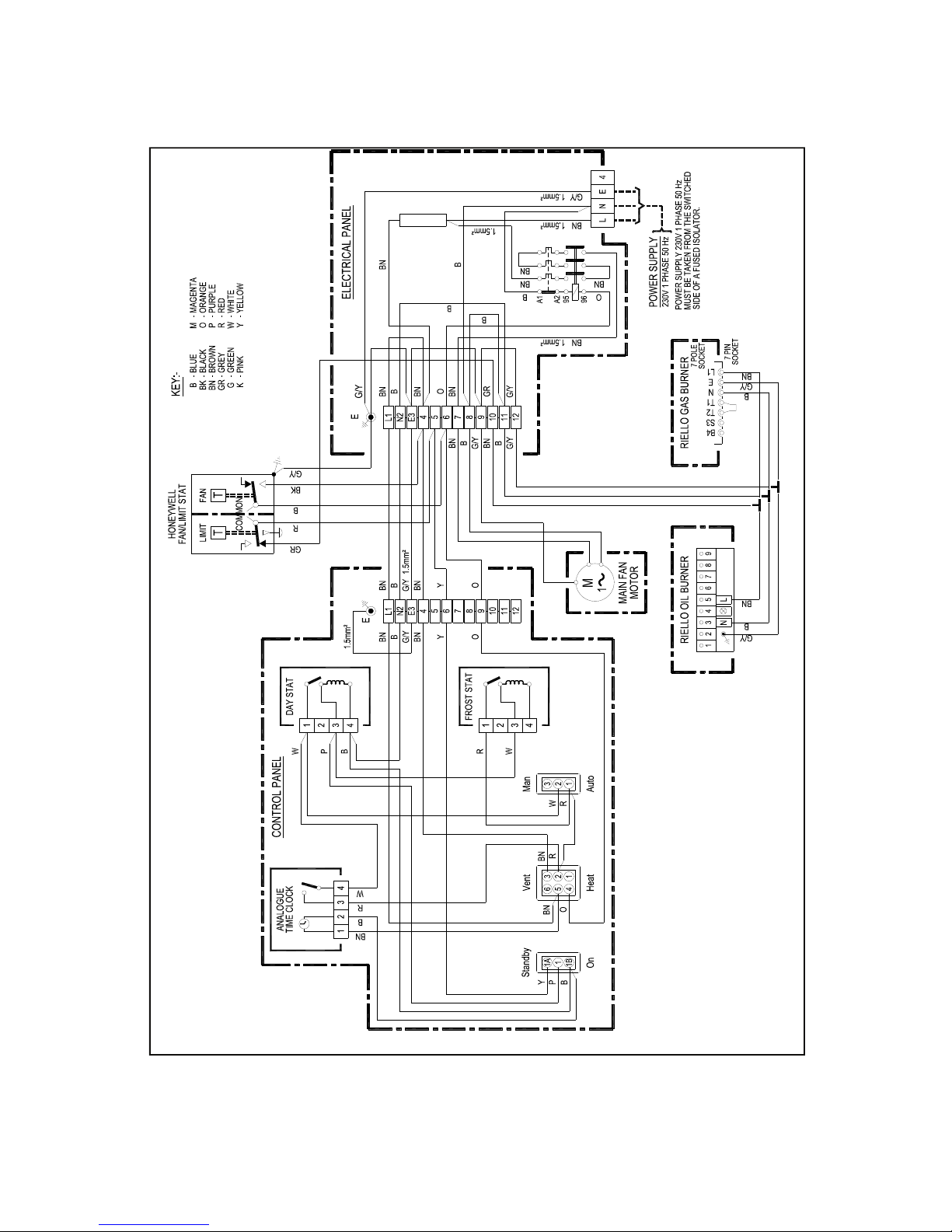
6A MCB
Wiring Diagram 20-45-182
400-500 ON/OFF Riello Gas or Oil Fired Burner Remote CP2 230/50/1ph
Page 38
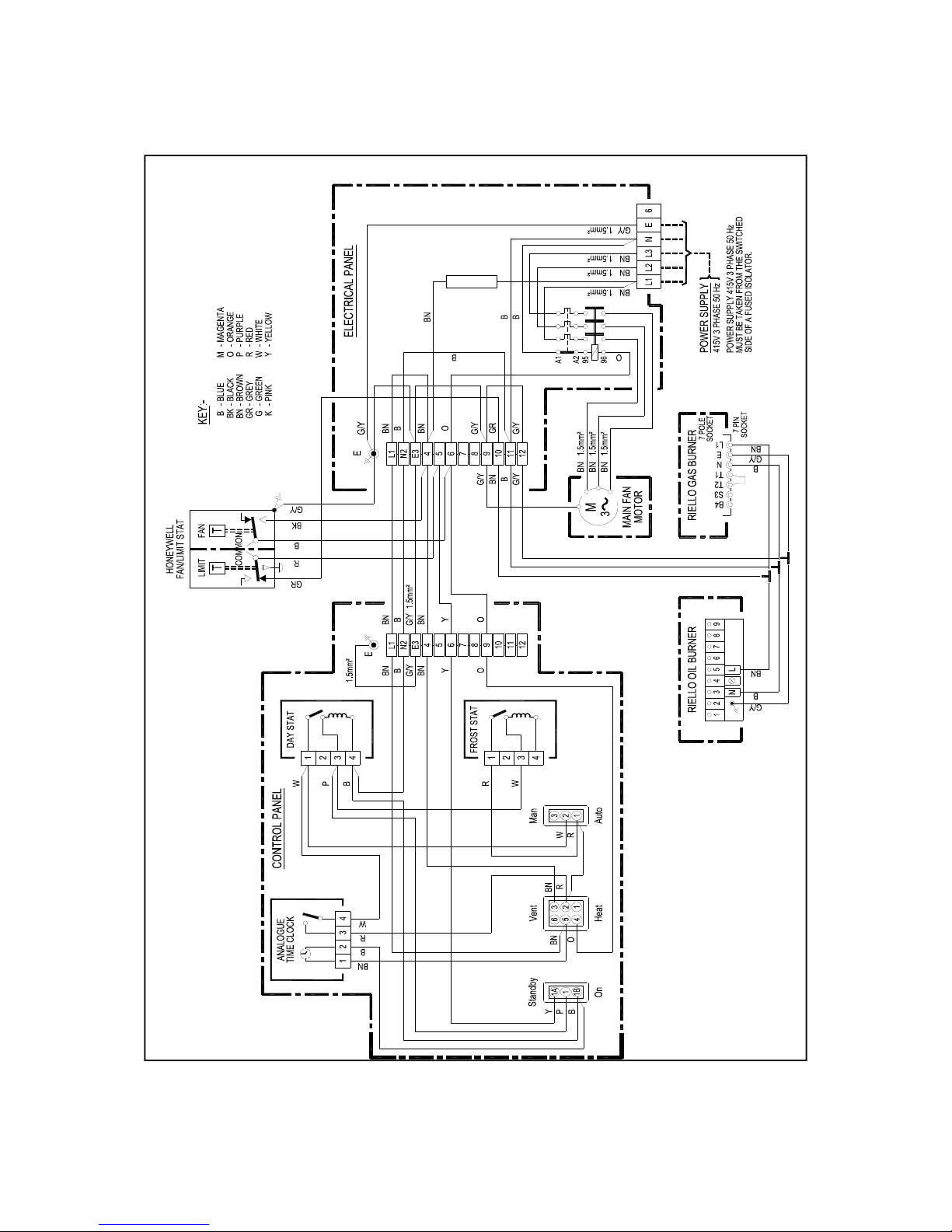
Wiring Diagram 20-45-183
200-1000 ON/OFF Riello Gas or Oil Fired Burner Remote CP2 415/50/3ph
6A MCB
Page 39
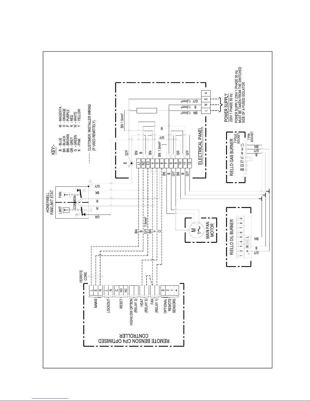
Wiring Diagram 20-45-311
100-300 ON/OFF Riello Gas or Oil Fired Burner Remote CP4 230/50/1ph
10A MCB
Page 40
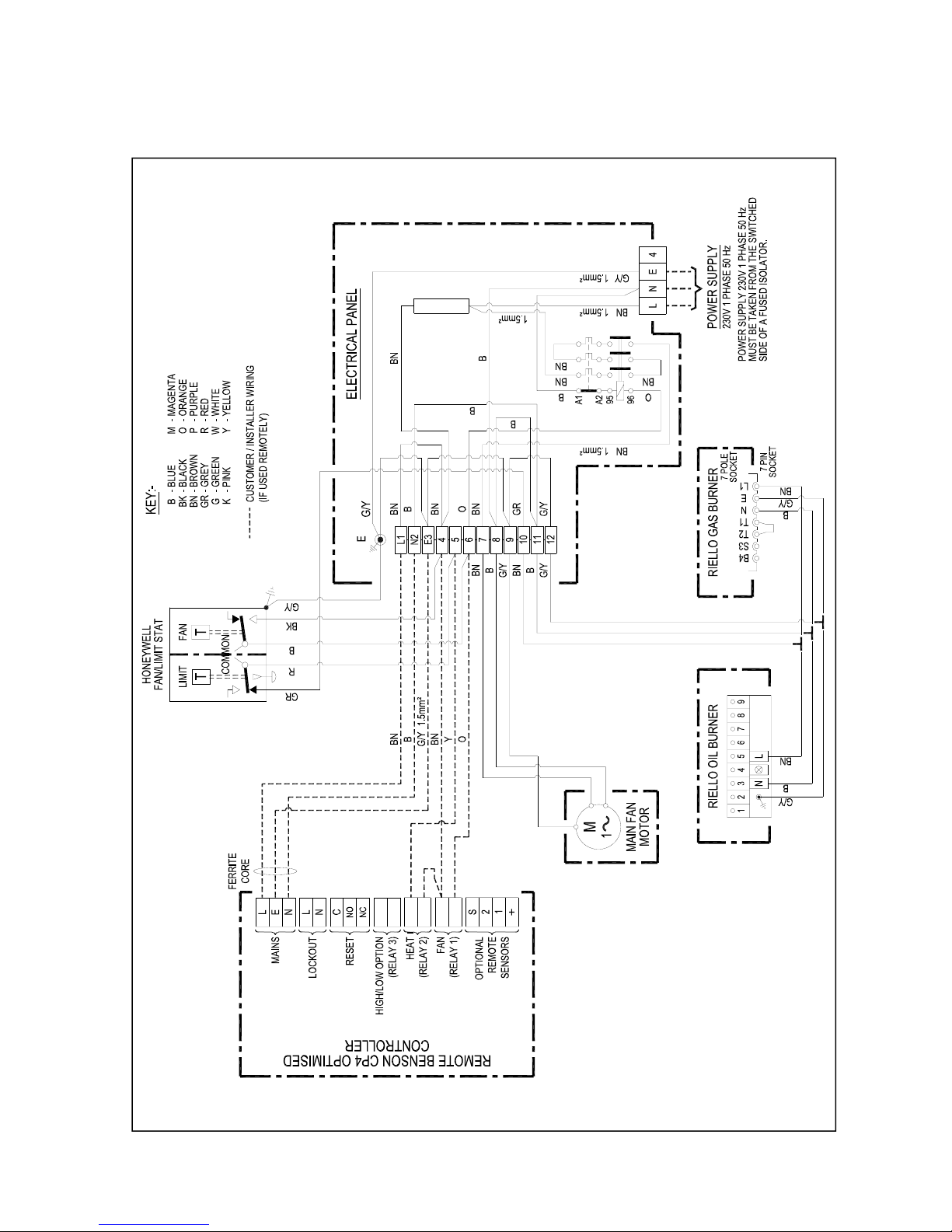
Wiring Diagram 20-45-312
400-500 ON/OFF Riello Gas or Oil Fired Burner Remote CP4 230/50/1ph
6A MCB
Page 41
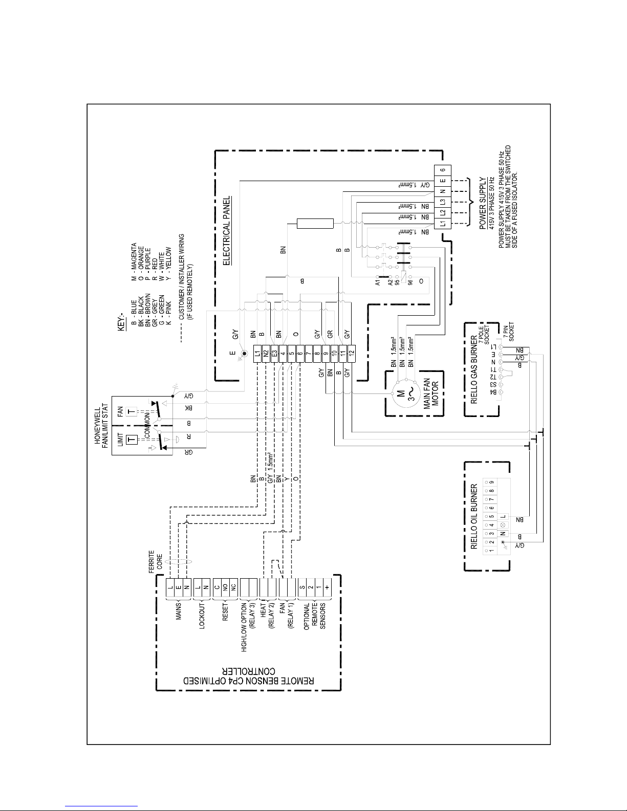
Wiring Diagram 20-45-313
400-1000 ON/OFF Riello Gas or Oil Fired Burner Remote CP4 415/50/3ph
6A MCB
Page 42
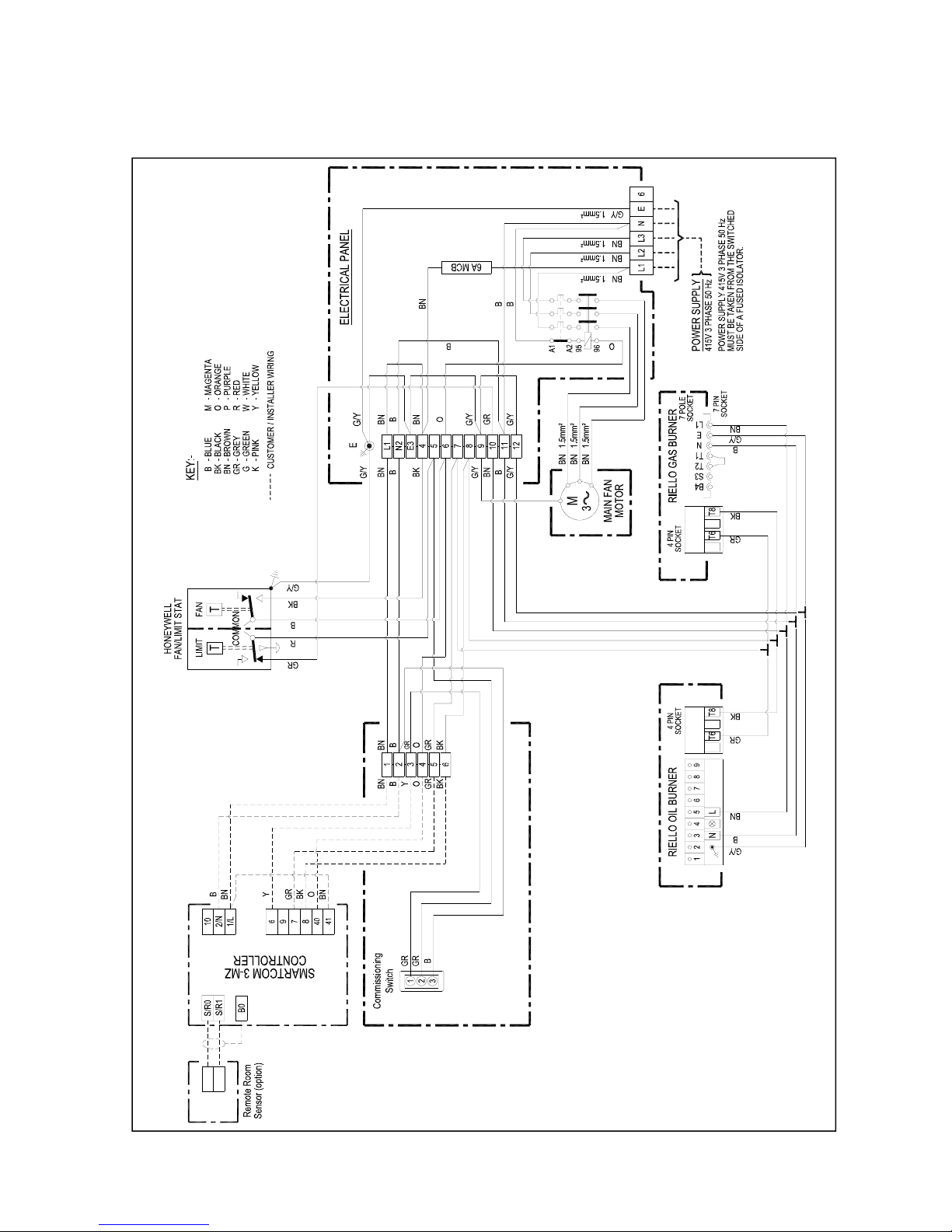
Wiring Diagram 20-45-439
200-1000 HI/LOW Riello Gas or Oil Fired Burner Remote SC³-MZ 415/50/3ph
Page 43
Page 44
Appliance Type B
23
PIN / report no 0063AQ0533
Country Approved Gas Category
AT,BG,CH,CY,CZ,DK,EE,ES,FI,GB,GR,HR,
IE,IT,IS,LT,LV,NO,PT,RO,SE,SI,SK,TR
I2H
BE,CZ,NL,FR,DE,IE,IT,ES,CH,PT,GB,SE,
SK,SL,PT,PL,TR
I3P
PL,LU,DE,RO
I2E
NL
I
2L
BE
I
2E(R)B
FR
I
2ESi
PL
I
2LS
PL
I
2LW
8.0 Technical Data
Page 45

Natural Gas (G20 I2H) Cabinet Heater
The minimum allowable pre-purge time requires calculating [BS EN1020:1998 clause 6.38].
To do this only Carbon Dioxide CO
2
figure needs to be measured.
E.G. on a model 300 the calculated minimum time is = 203.6 / ((100 / CO2) + 1)
If the measured CO
2
is 9.7%
Then 100 / 9.7 = 10.3
10.3 + 1 = 11.3
Therefore minimum pre-purge time is = 203.6 / 11.3 = 18.0 seconds
The calculation to be conducted is given below for all models:
Model 100 Minimum pre-purge time = 241.4 / ((100 / CO2) + 1)
Model 125 Minimum pre-purge time = 193.8 / ((100 / CO2) + 1)
Model 150 Minimum pre-purge time = 157.9 / ((100 / CO2) + 1)
Model 200 Minimum pre-purge time = 310.1 / ((100 / CO2) + 1)
Model 250 Minimum pre-purge time = 245.5 / ((100 / CO2) + 1)
Model 300 Minimum pre-purge time = 203.6 / ((100 / CO2) + 1)
Model 400 Minimum pre-purge time = 212.9 / ((100 / CO2) + 1)
Model 500 Minimum pre-purge time = 188.5 / ((100 / CO2) + 1)
Model 600 Minimum pre-purge time = 181.0 / ((100 / CO2) + 1)
Model 700 Minimum pre-purge time = 151.6 / ((100 / CO2) + 1)
Model 800 Minimum pre-purge time = 231.4 / ((100 / CO2) + 1)
Model 1000 Minimum pre-purge time = 191.2 / ((100 / CO2) + 1)
Model 1200 Minimum pre-purge time = 293.2 / ((100 / CO2) + 1)
Model 1300 Minimum pre-purge time = 263.7 / ((100 / CO2) + 1)
The pre-purge time must then be measured. If the measured pre-purge time
is lower than the calculated time STOP and contact Benson Heating.
Page 46

Propane (G31 I
3P
) Cabinet Heater
The minimum allowable pre-purge time requires calculating [BS EN1020:1998 clause 6.38].
To do this only the Carbon Dioxide CO
2
figure needs to be measured.
E.G. on a model 125 the calculated minimum time is = 490.7 / ((300 / CO2) + 2.01)
If the measured CO
2
is 11.2%
Then 300 / 11.2 = 26.79
26.79 + 2.01 = 28.8
Therefore minimum pre-purge time is = 490.7/28.8 = 17.0 seconds
The calculation to be conducted is given below for all models:
Model 100 Minimum pre-purge time = 611.2 / ((300 / CO2) + 2.01)
Model 125 Minimum pre-purge time = 490.7 / ((300 / CO2) + 2.01)
Model 150 Minimum pre-purge time = 399.9 / ((300 / CO2) + 2.01)
Model 200 Minimum pre-purge time = 785.2 / ((300 / CO2) + 2.01)
Model 250 Minimum pre-purge time = 621.5 / ((300 / CO2) + 2.01)
Model 300 Minimum pre-purge time = 515.4 / ((300 / CO2) + 2.01)
Model 400 Minimum pre-purge time = 539.0 / ((300 / CO2) + 2.01)
Model 500 Minimum pre-purge time = 477.3 / ((300 / CO2) + 2.01)
Model 600 Minimum pre-purge time = 458.2 / ((300 / CO2) + 2.01)
Model 700 Minimum pre-purge time = 383.9 / ((300 / CO2) + 2.01)
Model 800 Minimum pre-purge time = 585.9 / ((300 / CO2) + 2.01)
Model 1000 Minimum pre-purge time = 484.0 / ((300 / CO2) + 2.01)
Model 1200 Minimum pre-purge time = 735.4 / ((300 / CO2) + 2.01)
Model 1300 Minimum pre-purge time = 667.5 / ((300 / CO2) + 2.01)
The pre-purge time must then be measured. If the measured pre-purge time is lower
than the calculated time STOP and contact Benson Heating.
Page 47
q1 is the heat of the dry products of combustion (% of heat released per unit volume of gas)
q2 is the heat of the water vapour contained in the products of combustion ( % of heat re-
leased per unit volume of gas)
c1 is the mean specific heat of the dry products of combustion (in MJ / m
3
K)
t1 is the average combustion air temperature (in
0
C)
t2 is the average temperature of the products of combustion (in
0
C)
Hi is the net calorific value of the gas at 1013 mbar and 15
0
C , dry (in MJ / m3)
Hs is the gross calorific value of the gas at 1013 mbar and 15
0
C , dry (in MJ / m3)
Vf is the volume of dry products of combustion per unit volume of gas (in m
3
)
Vf is calculated from the volume of CO
2
(V CO2) produced by the combustion of 1m3 of gas
(see table below), and from the CO
2
content of the products of combustion (V CO2,M)
V CO
2
Vf = ------------------ x 100
V CO
2
M
Ref. Gas G110 G120 G20 G25 G30 G31
V CO2 0.26 0.32 1 0.86 4 3
The net efficiency E (net) (in %) is given by: E (net) = 100 - ( q1+ q2 )
where and
t2 - t1 Hs - Hi
q1 = C1 x Vf ------------ x 100 q2 = 0.077 ------------ (t2 - t1 )
Hi Hi
Note The required net efficiency must not be less than 84%
On heaters that are fitted with modulating or Hi / Lo burners the testing is carried out with
the appliance adjusted to give the minimum rate, and the following formula is used.
10 ( Qn - Qmin )
Emin > E n - ---------------------- in %
Qn
Qn is the nominal heat input
Qmin is the minimum obtainable heat input
En is the net efficiency determined by the Notified Body
Note The minimum net efficiency for appliances fitted with modulating or Hi / Lo burners
must not be less than 79%.
MODEL 100 125 150 200
HEAT
OUTPUT
kW/hr
Btu/hr
29.16
99,500
36.21
123,500
43.32
147,800
57.96
197,800
HEAT INPUT
(GROSS)
KW/hr
Btu/hr
35.40
120,800
44.09
150,500
54.10
184,500
70.31
239,900
NETT EFFICIENCY % 91.49 91.21 88.93 91.54
GROSS EFFICIENCY % 82.4 82.2 80.1 82.4
NAT GAS
CONSUMPTION
M3/hr
Ft
3
/hr
3.34
118
4.19
148
5.09
180
6.68
236
BURNER TYPE RIELLO GS5 GS5 GS5 GS10
NAT GAS BURNER PRESSURE
(zero resistance cover fitted)
Mbar
Ins WG
2.3
0.9
2.5
1.0
3.6
1.4
2.5
1.0
NAT GAS MINIMUM GAS INLET PRESSURE Mbar 17.5 17.5 17.5 17.5
NAT GAS HEAD SETTING(zero flue resistance) Number 1 3 5 2
NAT GAS AIR SETTING (zero flue resistance) Number 2.8 3 4.5 2.2
GAS
CONSUMPTION
PROPANE
M3/hr
Ft
3
/hr
L/h
1.4
51
5.3
1.8
63
6.6
2.1
76
7.9
2.8
101
10.6
LPG BURNER PRESSURE
(zero resistance cover fitted)
Mbar
Ins WG
TBA 4.9
1.9
TBA 4.1
1.64
LPG MINIMUM GAS INLET PRESSURE Mbar 37.0 37.0 37.0 37.0
LPG HEAD SETTING (zero flue resistance) Number TBA 3 TBA 2
LPG AIR SHUTTER SET (zero flue resistance) Number TBA 4.2 TBA 2.6
GAS CONNECTION RC½ RC½ RC½ RC½
AVAILABLE OUTLET
PRESSURE
Pascals
Ins WG
75
0.3
100
0.4
100
0.4
75
0.3
NOZZLE DISCHARGE
VELOCITY
M/sec
Ft/min
5.73
1124
4.53
888
4.53
888
6.57
1288
AIR THROW
(APPROX)
Mtrs
Ft
14
45
14
45
14
45
17.1
55
AIR
DELIVERY
M3/sec
Ft
3
/min
0.61
1300
0.71
1500
0.71
1500
1.03
2180
TEMPERATURE RISE
THROUGH HEATER
Deg C
Deg F
39
70
41.9
76
50.3
90
46.3
83
SOUND LEVEL Dba 67 69 69 72
COMBUSTION CHAMBER (press) Mbar 0.21 0.21 0.21 0.24
FLUE
RESISTANCE
Min Mbar
Max Mbar
-0.2
0.6
-0.2
0.6
-0.2
0.6
-0.2
0.6
FLUE DIAMETER Mm 125 125 125 150
ELECTRICAL SUPPLY Standard 230/1/50 230/1/50 230/1/50 230/1/50
RATED INPUT KW 0.55 0.55 0.55 1.1
FUSED ISOLATOR SIZE Amps 16 16 16 20
RUNNING CURRENT Amps 3.2 4.8 4.8 6
ELECTRICAL SUPPLY Optional N/A N/A N/A 415/3/50
RATED INPUT KW N/A N/A N/A 0.75
FUSED ISOLATOR SIZE Amps N/A N/A N/A 16
RUNNING CURRENT Amps N/A N/A N/A 2.2
ELECTRICAL PROTECTION IP 20 20 20 20
WEIGHT Kg 196 196 196 241
AIR NOZZLE SIZE Ins 9.4 9.4 9.4 9.4
NOZZLE AMOUNT No 2 2 2 2
FLUE TEMPERATURE (GROSS) @ 200C Ambient 200 205 253 200
8.1 Technical Data
Page 48
MODEL 250 300 400 500
HEAT
OUTPUT
kW/hr
Btu/hr
73.00
249,000
86.05
293,600
117.02
399,300
132.16
450,900
HEAT INPUT
(GROSS)
KW/hr
Btu/hr
88.83
303,000
107.12
365,500
142.78
487,200
161.23
550,100
NETT EFFICIENCY % 91.26 89.21 91.02 91.03
GROSS EFFICIENCY % 82.2 80.3 82.0 82.0
NAT GAS
CONSUMPTION
M3/hr
Ft
3
/hr
8.5
300
10.1
359
13.6
480
15.3
541
BURNER TYPE RIELLO GS10 GS10 GS20 GS20
NAT GAS BURNER PRESSURE
(zero resistance cover fitted)
Mbar
Ins WG
4.1
1.6
5.3
2.1
4.0
1.6
4.6
1.8
NAT GAS MINIMUM GAS INLET PRESSURE Mbar 17..5 17.5 17.5 17.5
NAT GAS HEAD SETTING (zero flue resistance) Number 3 5 3 5
NAT GAS AIR SETTING (zero flue resistance) Number 3.6 6 3.2 4.2
GAS
CONSUMPTION
PROPANE
M3/hr
Ft
3
/hr
L/h
3.6
128
13.4
4.2
150
15.7
5.9
207
21.8
7.4
262
27.6
LPG BURNER PRESSURE
(zero resistance cover fitted)
Mbar
Ins WG
TBA TBA TBA TBA
LPG MINIMUM GAS INLET PRESSURE Mbar 37.0 37.0 37.0 37.0
LPG HEAD SETTING (zero flue resistance) Number TBA TBA TBA TBA
LPG AIR SHUTTER SET (zero flue resistance) Number TBA TBA TBA TBA
GAS CONNECTION RC½ RC½ RC¾ RC¾
AVAILABLE OUTLET
PRESSURE (STD)
Pascals
Ins WG
100
0.4
100
0.4
137
0.55
150
0.6
NOZZLE DISCHARGE
VELOCITY
M/sec
Ft/min
5.91
1159
5.91
1159
7.55
1481
6.98
1369
AIR THROW
(APPROX)
Mtrs
Ft
17.1
55
17.1
55
20.2
65
20.2
65
AIR
DELIVERY(STD)
M3/sec
Ft
3
/min
1.39
2950
1.39
2950
2.15
4550
2.65
5620
TEMPERATURE RISE
THROUGH HEATER
Deg C
Deg F
42.8
77
49.8
90
45.1
81
44.5
81
SOUND LEVEL Dba 72 72 74 75
COMBUSTION CHAMBER (press) Mbar 0.24 0.34 0.56 0.88
FLUE
RESISTANCE
Min Mbar
Max Mbar
-0.2
0.6
-0.2
0.6
-0.2
0.6
-0.2
0.6
FLUE DIAMETER Mm 150 175 175 175
ELECTRICAL SUPPLY Standard 230/1/50 230/1/50 415/3/50 415/3/50
RATED INPUT KW 1.1 1.1 1.5 2.2
FUSED ISOLATOR SIZE Amps 20 20 16 16
RUNNING CURRENT Amps 7.2 7.2 3.6 5.2
ELECTRICAL SUPPLY Optional 415/3/50 415/3/50 230/1/50 230/1/50
RATED INPUT KW 0.75 0.75 1.5 2.2
FUSED ISOLATOR SIZE Amps 16 16 40 40
RUNNING CURRENT Amps 2.2 2.2 12 14
ELECTRICAL PROTECTION IP 20 20 20 20
WEIGHT Kg 243 243 330 332
AIR NOZZLE SIZE Ins 9.4 9.4 11 11
NOZZLE AMOUNT No 3 3 3 4
FLUE TEMPERATURE (GROSS) @ 200 C Ambient 210 250 210 210
Technical Data
Page 49
MODEL 600 700 800
HEAT
OUTPUT
kW/hr
Btu/hr
176.59
602,500
204.99
699,400
234.96
801,700
HEAT INPUT
(GROSS)
KW/hr
Btu/hr
214.22
730,900
255.72
872,500
285.70
974,800
NETT EFFICIENCY % 91.54 90.00 91.07
GROSS EFFICIENCY % 82.4 80.2 82.05
NAT GAS
CONSUMPTION
M3/hr
Ft
3
/hr
20.2
715
23.9
844
27.0
956.5
BURNER TYPE RIELLO GS20 RS34.1 RS34.1
NAT GAS BURNER PRESSURE
(zero resistance cover fitted)
Mbar
Ins WG
5.9
2.3
7.2
2.9
7.4
2.9
NAT GAS MINIMUM INLET PRESSURE Mbar 17.5 17.5 17.5
NAT GAS HEAD SETTING (zero flue resistance) Number 6 3 3
NAT GAS AIR SETTING (zero flue resistance) Number 8 2.5 3.50
GAS
CONSUMPTION
PROPANE
M3/hr
Ft
3
/h
L/h
8.5
301
31.6
10.2
361
37.9
11.7
414
43.5
LPG BURNER PRESSURE
(zero resistance cover fitted)
Mbar
Ins WG
TBA TBA TBA
LPG MINIMUM GAS INLET PRESSURE Mbar 37.0 37.0 37.0
LPG HEAD SETTING (zero flue resistance) Number TBA TBA TBA
LPG AIR SET TING (zero flue resistance) Number TBA TBA TBA
GAS CONNECTION RC1 RC1¼ RC1¼
AVAILABLE OUTLET
PRESSURE (STD)
Pascals
Ins WG
175
0.7
188
0.75
125
0.5
NOZZLE DISCHARGE
VELOCITY
M/sec
Ft/min
6.13
1203
6.71
1315
6.55
1285
AIR THROW
(APPROX)
Mtrs
Ft
20.2
65
21.7
70
21.7
70
AIR
DELIVERY(STD)
M3/sec
Ft
3
/min
3.11
6600
3.4
7200
4.32
9150
TEMPERATURE RISE
THROUGH HEATER
Deg C
Deg F
44.7
81
49.2
88
44.2
79
SOUND LEVEL Dba 78 78 79
COMBUSTION CHAMBER (press) Mbar 0.54 0.62 0.67
FLUE
RESISTANCE
Min Mbar
Max Mbar
-0.2
0.6
-0.4
1.6
-0.4
1.6
FLUE DIAMETER Mm 200 200 225
ELECTRICAL SUPPLY Standard 415/3/50 415/3/50 415/3/50
RATED INPUT KW 3 3 4
FUSED ISOLATOR SIZE Amps 25 25 32
RUNNING CURRENT Amps 6.5 7.5 8.4
ELECTRICAL SUPPLY Standard N/A N/A N/A
RATED INPUT KW N/A N/A N/A
FUSED ISOLATOR SIZE Amps N/A N/A N/A
RUNNING CURRENT Amps N/A N/A N/A
ELECTRICAL PROTECTION IP 20 20 20
WEIGHT Kg 525 540 630
AIR NOZZLE SIZE Ins 12.6 12.6 14.6
NOZZLE AMOUNT No 4 4 4
FLUE TEMPERATURE (GROSS) @ 200 C Ambient 200 225 205
Technical Data
Page 50
MODEL 1000 1200 1300
HEAT
OUTPUT
kW/hr
Btu/hr
283.67
967,900
349.98
1194,100
380.45
1298,100
HEAT INPUT
(GROSS)
KW/hr
Btu/hr
345.88
1180,150
426.66
1455,800
470.08
1603,900
NETT EFFICIENCY % 91.08 91.09 89.88
GROSS EFFICIENCY % 82 82 80.2
NAT GAS
CONSUMPTION
M3/hr
Ft
3
/hr
33.0
1168
40.7
1437
45.8
1617
BURNER TYPE RIELLO RS34.1 RS44.1 RS44.1
NAT GAS BURNER GAS PRESSURE
(zero resistance cover fitted)
Mbar
Ins WG
11.2
4.5
7.6
3.0
NAT GAS MINIMUM INLET PRESSURE Mbar 17.5 17.5 17.5
NAT GAS HEAD SETTING zero flue resistance Number 6 TBA
NAT GAS AIR SHUTTER SET zero flue resistance Number 3.66 TBA
GAS
CONSUMPTION
PROPANE
M3/hr
Ft
3
/hr
L/h
14.36
516
54.2
16.8
595
62.4
19.0
669
70.4
LPG BURNER GAS PRESSURE
(zero resistance cover fitted)
Mbar
Ins WG
TBA TBA TBA
LPG MINIMUM GAS INLET PRESSURE Mbar 37.0 37.0 37.0
LPG HEAD SETTING zero flue resistance Number TBA TBA TBA
LPG AIR SHUTTER SET zero flue resistance Number TBA TBA TBA
GAS CONNECTION RC1¼ RC1½ RC2"
AVAILABLE OUTLET
PRESSURE (STD)
Pascals
Ins WG
175
0.7
250
1
250
1
NOZZLE DISCHARGE
VELOCITY
M/sec
Ft/min
7.39
1445
8.49
1665
8.49
1665
AIR THROW
(APPROX)
Mtrs
Ft
24.8
80
31.1
100
31.1
100
AIR
DELIVERY(STD)
M3/sec
Ft
3
/min
4.86
10,300
6.88
14,680
6.88
14,680
TEMPERATURE RISE
THROUGH HEATER
Deg C
Deg F
48
86
40.2
72
45
81
SOUND LEVEL Dba 81 81 81
COMBUSTION CHAMBER (press) Mbar 0.92 0.9 0.9
FLUE
RESISTANCE
Min Mbar
Max Mbar
-0.4
1.6
-0.4
1.6
-0.4
1.6
FLUE DIAMETER Mm 225 250 250
ELECTRICAL SUPPLY Standard 415/3/50 415/3/50 415/3/50
RATED INPUT KW 5.5 7.5 7.5
FUSED ISOLATOR SIZE Amps 32 64 64
RUNNING CURRENT Amps 11 17 17
ELECTRICAL PROTECTION IP 20 20 20
WEIGHT Kg 646 1090 1090
AIR NOZZLE SIZE Ins 14.6 18.5 18.5
NOZZLE AMOUNT No 4 4 4
FLUE TEMPERATURE (GROSS) @ 200C Ambient 200 206 233
Technical Data
Page 51

9.0 Reference Information
Doc/Ref Title/Subject
BS EN 1020 :1998 Non Domestic Gas Fired Forced Convection
Air Heaters For Space Heating
BS EN 292 Parts 1 and 2; 1992 Safety of Machinery
BS EN 60204 Part 1; 1993 Safety of Machinery - Electrical
BS EN 60335 Part 1; 1988 Safety of Electrical Appliances
BS EN 55014 1993 Electromagnetic Compatibility
BS EN 50165 1997 Safety of Electrical Equipment
BS 5854 1980 Code of Practice - Flues/Flue Structures
BS 6891 1988 Installation of Pipework < 28mm
BS 5991 1989 Indirect Gas Fired Heaters < 2 MW
BS 715 1993 Metal Flue Pipes and Fittings
BS 5440 Part 1 ; 1990 Specification/Installation of Flues
BS 5440 Part 2 ; 1989 Ventilation Requirements Gas Appliances
ISO 7/1 (see also BS21 ) Specification for Metric Pipe Threads
ISO 228/1 See also BS 2779 and BS 5380) Pipe Threads Seals and Couplings
UP/1 (Replaces IM/5 & IM/16 ) Installation of Gas Appliances
UP/2 (Replaces IM/7 ) Installation of Gas Appliances
Page 52
DESCRIPTION 100 125 150 200
Stackbox Assy 31-28-078 31-28-078 31-28-078 31-24-074
Flue Box Cover Assy 31-28-115 31-28-115 31-28-115 20-45-094
Fan/Limit Thermostat 28-60-023 28-60-023 28-60-023 28-60-023
Fan/ limit Stat Gasket 20-33-549 20-33-549 20-33-549 20-33-549
Burner Plate Gasket 31-28-080 31-28-080 31-28-080 30-40-156
Pressure Relief Gasket 31-28-080 31-28-080 31-28-080 31-27-121
Sight Glass 20-30-151 20-30-151 20-30-151 20-30-151
Sight Glass Holder 20-30-061 20-30-061 20-30-061 20-30-061
Sight Glass Gasket 31-28-084 31-28-084 31-28-084 31-28-084
Time Clock 28-15-008 28-15-008 28-15-008 28-15-008
Thermostat Room 28-16-031 28-16-031 28-16-031 28-16-031
Thermostat Frost. 28-16-044 28-16-044 28-16-044 28-16-044
Rocker Switch Red Neon 28-40-105 28-40-105 28-40-105 28-40-105
Rocker Switch Dual Black 28-40-106 28-40-106 28-40-106 28-40-106
Rocker Switch Black 28-40-104 28-40-104 28-40-104 28-40-104
Fuse 1ph 28-07-049 28-07-049 28-07-049 28-07-049
Motorised Fan 1ph 28-09-049 28-09-049 28-09-049 28-09-002
Fan Restrictor 31-30-017 N/A N/A 31-30-016
Nat Gas Burner c/w Gas Train 29-99-445 29-99-445 29-99-445 29-99-445
LPG Conversion Kit 30-00-882 30-00-882 30-00-882 30-00-882
Control CP4 CP4 CP4 CP4
Parts list
Page 53

DESCRIPTION 250 300 400
Stackbox Assy 31-24-074 31-27-123 31-27-123
Flue Box Cover Assy 20-45-094 20-45-094 20-45-094
Overload N/A N/A 28-11-053
Contactor N/A N/A 28-11-057
Fan/Limit Thermostat 28-60-023 28-60-023 28-60-023
Fan/ limit Stat Gasket 20-33-549 20-33-549 20-33-549
Burner Plate Gasket 30-40-156 30-40-156 31-27-121
Pressure Relief Gasket 31-27-121 31-27-121 31-27-121
Sight Glass 20-31-151 20-30-151 20-30-151
Sight Glass Holder 20-30-161 20-30-061 20-30-061
Sight Glass Gasket 31-28-084 31-28-084 31-28-084
Time Clock 28-15-008 28-15-008 28-15-008
Thermostat Room 28-16-031 28-16-031 28-16-031
Thermostat Frost 28-16-044 28-16-044 28-16-044
Rocker Switch Red Neon 28-40-105 28-40-105 28-40-105
Rocker Switch Dual Black 28-40-106 28-40-106 28-40-106
Rocker Switch Black 28-40-104 28-40-104 28-40-104
Fuse 1ph 28-07-049 28-07-049 N/A
Fuse 3ph 28-07-048 (OPT) 28-07-048 (OPT) 28-07-048
Fan 28-09-002 28-09-002 28-09-003
Fan Pulley N/A N/A 28-65-092
Motor N/A N/A 28-10-127
Motor Pulley N/A N/A 28-65-065
Belt N/A N/A 09-16-110(2)
Burner 29-99-446 29-99-446 29-99-448
LPG Conversion Kit 30-00-884 30-00-884 30-00-886
Control CP4 CP4 CP4
Page 54
DESCRIPTION 500 600 700 800
Stackbox Assy 31-27-123 20-46-307 20-46-307 20-47-425
Flue Box Cover Assy 20-45-094 20-46-310 20-46-310 20-46-310
Overload 28-11-056 28-11-055 28-11-055 28-11-054
Contactor 28-11-057 21-11-057 21-11-057 28-11-057
Fan/Limit Thermostat 28-60-023 28-60-023 28-60-023 28-60-023
Fan/ limit Stat Gasket 20-33-549 20-33-549 20-33-549 20-33-549
Burner Plate Gasket 31-27-121 31-27-121 31-29-046 31-29-046
Pressure Relief Gasket 31-27-121 20-46-354 20-46-354 20-46-354
Sight Glass 20-30-151 20-30-151 20-30-151 20-30-151
Sight Glass Holder 20-30-061 20-30-061 20-30-061 20-30-061
Sight Glass Gasket 31-28-084 31-28-084 31-28-084 31-28-084
Time Clock 28-15-008 28-15-008 28-15-008 28-15-008
Thermostat Room 28-16-031 28-16-031 28-16-031 28-16-031
Thermostat Frost 28-16-044 28-16-044 28-16-044 28-16-044
Rocker Switch Red Neon 28-40-105 28-40-105 28-40-105 28-40-105
Rocker Switch Dual Black 28-40-106 28-40-106 28-40-106 28-40-106
Rocker Switch Black 28-40-104 28-40-104 28-40-104 28-40-104
Fuse Holder 28-07-050 28-07-050 28-07-050 28-07-050
Fuse 3ph 28-07-048 28-07-048 28-07-048 28-07-048
Fan 28-09-003 28-09-004 28-09-004 28-09-043
Fan Pulley 28-65-096 28-65-105 28-65-105 28-65-074
Fan Taper lock 28-66-025 28-66-025 28-66-136 28-66-136
Motor 28-10-015 28-10-120 28-10-120 28-10-026
Motor Pulley 28-65-063 28-65-063 28-65-072 28-65-180
Motor Taper lock 28-66-125 28-65-105 28-66-028 28-66-028
V Belt 09-16-106 (2) 09-16-126 (2) 09-06-126(2) 09-16-116 (3)
Nat Gas Burner c/w Gas Train 29-99-448 29-99-449 29-99-552 29-99-552
Air Head N/A N/A 30-10-145 30-10-145
LPG Conversion Kit 30-00-886 30-00-886 30-10-423 30-10-423
Control CP4 CP4 CP4 CP4
Page 55
DESCRIPTION 1000 DESCRIPTION 1200 1300
Stackbox Assy 20-47-425
Gas Exit Duct Assy V
20-27-090 20-27-090
Flue Box Cover Assy 20-46-310
Gas Exit Duct Assy H
20-27-092 20-27-092
Overload 28-11-111 Star Delta Starter 28-11-044 28-11-045
Contactor 28-11-057
Fan/Limit Thermostat 28-60-023 Fan/Limit Thermostat 28-60-021 28-60-021
Fan/ limit Stat Gasket 20-33-549 Fan/ limit Stat Gasket 20-33-549 20-33-549
Burner Plate Gasket 31-29-046 Burner Plate Gasket 31-29-046 31-29-046
Pressure Relief Gasket 20-46-354 Pressure Relief Gasket 20-46-354 20-46-354
Sight Glass 20-30-151 Sight Glass 20-30-151 20-30-151
Sight Glass Holder 20-30-061 Sight Glass Holder 20-30-061 20-30-061
Sight Glass Gasket 31-28-084 Sight Glass Gasket 31-28-084 31-28-084
Time Clock 28-15-008 Time Clock 28-15-008 28-15-008
Thermostat Room 28-16-031 Thermostat Room 28-16-031 28-16-031
Thermostat Frost 28-16-044 Thermostat Frost 28-16-044 28-16-044
Rocker Switch Red Neon 28-40-105 Rocker Switch Red Neon 28-40-105 28-40-105
Rocker Switch Dual Black 28-40-106 Rocker Switch Dual Black 28-40-106 28-40-106
Rocker Switch Black 28-40-104 Rocker Switch Black 28-40-104 28-40-104
Fuse Holder 28-07-050 Fuse Holder 28-07-050 28-07-050
Fuse 3ph 28-07-048 Fuse 3ph 28-07-048 28-07-048
Fan 28-09-043 Fan Drive Assy (Nozzled)
Fan Drive Assy (Ducted)
28-09-087
20-27-311
28-09-087
20-27-311
Fan Pulley 28-65-074 Driven Pull ey (Nozzled)
Driven Pulley (Ducted)
28-65-049
28-65-054
28-65-049
28-65-054
Fan Taper lock 28-66-136 Taper lock Driven (Nozzled)
Taper lock Driven (Ducted)
28-66-136
28-66-019
28-66-136
28-66-019
Motor 28-10-021 Motor (Nozzled)
Motor (Ducted)
28-10-024
28-10-025
28-10-024
28-10-025
Motor Pulley 28-65-181 Drive Pulley (Nozzled)
Drive Pulley (Ducted)
28-65-047
28-65-053
28-65-047
28-65-053
Motor Taper lock 28-66-013 Taper lock Drive (Nozzled)
Taper lock Drive (Ducted)
28-66-013
28-66-042
28-66-013
28-66-042
V Belt (3) 09-16-116 V Belt (3) Ducted
V Belt (3) Nozzled
09-16-126
09-16-138
09-16-126
09-16-138
Nat Gas Burner c/w Gas Train 29-99-552 Nat Gas Burner c/w Gas Train 29-99-551 29-99-551
Air Head 30-10-145 Air Head 30-10-145 30-10-146
LPG Conversion Kit 30-10-423 LPG Conversion Kit 30-10-423 30-10-424
Control CP4 Control CP4 CP4
Page 56

S E C T I O N 2
B A S I C U S E R
I N S T R U C T I O N S
10.0 Introduction
The following information is relevant to the
Gas fired Cabinet Heater range
manufactured by Benson Heating. These
heaters are manufactured within a strictly
controlled quality system to ISO 9001.
All Benson Heating gas fired Cabinet
Heaters are CE marked, having been found
to satisfy the essential requirements of the
following European Directives.
Machinery Directive (89/392/EEC)
Low Voltage Directive (73/23/EEC & 93/68/
EEC)
Electromagnetic Compatibility Directive
(89/336/EEC & 91/31/EEC)
Product Liability Directive (65/374/EEC)
Benson Heating support all new products
being supplied to their customers with a
comprehensive information pack, and it is the
responsibility of the owner, user, or hirer, of
such products supplied by Benson Heating to
ensure that operators are provided with the
operator manual, and that they are suitably
instructed regarding the purpose of the
manual and safety instructions. In addition to
this, operators must also be suitably and
adequately trained in the use of the product.
Contained within the text of this manual, the
words 'Caution' and 'Warning' are used to
highlight certain points.
Caution is used when failure to follow or
implement the instruction(s) can lead to a
premature failure or damage being
occasioned to the heater or its component
parts.
Warning is used when failure to heed or
implement the instruction(s) can lead not
only to component damage, but can also
lead to a hazardous situation being created
where there is a risk of personal injury or
death
10.1 Commissioning and hand over
Warning
As part of the commissioning programme,
the commissioning engineer must go through
the following with the operator.
(i) Lighting, shutdown, and operational
information.
(ii) Safety features, data plate, and labeling.
(iii) The requirement for regular inspection especially if the heater is within a more
demanding environment - and the need for
regular servicing, carried out by competent
and qualified engineers.
Caution
After approximately 100 hours of running, the
tension on the fan belts must be checked to
ensure that it is correct, and that the belts
have not stretched.
It is strongly advised that this is undertaken
by the commissioning engineer, and not the
operator
10.2 Servicing
Warning
Servicing must be carried out on a regular
basis, the maximum interval between
services being one year.
It is a requirement that only suitably qualified
and competent persons are allowed to
undertake the servicing.
Benson Heating advise that the planned
service schedule as detailed in section 5.1 of
the Installation, Commissioning and
Servicing Manual is adopted by the user.
Further details are available from either
Benson Heating or from the commissioning
engineer.
10.3 Start up procedure CP4 OPTION
(a) Ensure that the gas cocks are open, and
that the mains electrical supply is turned on
(b) Ensure that the CP4 has been correctly
programmed
(c) Ensure programme is displaying Heat On
setting
Page 57

ANALOGUE OPTION
(d) Ensure On Standby switch ON
(e) Ensure heat vent switch is set for ‘heat’
(f) Check for the following burner sequence
interval o p e r a n d
1 <5s Combustion air damper actuated
fan motor initiates purge cycle...
2 <40s Pilot valve opens ignition
transformer provides spark for
Pilot ignition and flame detection
3 <40s Pilot ignition and Burner ignition
4 <60s Burner ignition start cycle
complete
Note
The time intervals within the ignition
sequence may vary slightly between models.
(f) The burner will continue to fire until heat is
no longer demanded.
10.4 Stop procedure CP4 OPTION
(a) Select standby , option 2 standby
(b) The fan motor will continue to run until
heat dissipation allows the fan and limit stat
to shut down the fan.
Stop procedure Analogue OPTION
a) Set switch to standby' position.
(b) The fan motor will continue to run until
heat dissipation allows the fan and limit stat
to shut down the fan.
Caution
Do not use the main electrical isolator to turn
off the heater, to do so can cause damage to
the heat exchanger and combustion chamber
and thereby invalidate the warranty.
10.5 Shut down procedure
(a) Follow steps 10.4 (a) and (b), when fan
stops turn main electrical isolator off, and
shut gas cocks
10.6 Ventilation only
CP4 OPTION
(a) Select Fan / Enter to confirm.
ANALOGUE OPTION
(b) Set Heat/Ventilate switch to 'ventilate'.
10.7 Lockout situations
If either the burner or the fan and limit stat go
to lockout, the lockout must be cleared
manually before the ignition sequence can
be re-initiated.
Caution
Repeated or frequent lockouts must be
investigated and their cause determined by a
qualified and competent engineer.
Page 58

Page 59

Page 60

BENSON HEATING LTD
LUDLOW ROAD
KNIGHTON
POWYS
LD7 1LP
Telephone +44 (0) 1547 528534
Facsimile +44 (0) 1547 520399
email [email protected]
Web www.bensonheating.com
 Loading...