


Headin
g
Place your message here. For m a xi m u m im pa ct, use two or three sentences.
BENSON
VARIANTE 2 RANGE
BI DIRECTIONAL
NATURAL GAS (G20 I2H)
PROPANE GAS (G31 I3P)
TUBULAR HEATER
I N S T A L L A T I O N C O M M I S S I O N I N G
S E R V I C I N G
U S E R I N S T R U C T I O N S
Issue 3
October 2007
THIS MANUAL SHOULD BE LEFT WITH THE END USER .
TO ENSURE SERVICE AND MAINTENANCE INFORMATION IS AVAILABLE ON SITE
BENSON

Section Contents Page No
1.0 Compliance Notices
4
1.1 Certificates of Conformity 5
1.2 General product Information 5
1.3 General Requirements 6
1.4 Delivery & Pre-installation Checks 6
1.5 Warranty 7
Special risk areas 7
2.0 Installation
8
2.1 Installation Clearances and Mounting Heights 8
2.2 Heater Mounting 8
2.3 Warm Air Circulation 9
2.4 Air Supply 9
2.5 Flue Installation 13
2.6 Electrical Installation 17
2.7 Gas Installation 18
3.0 Commissioning
19
3.1 Electrical Pre tests 19
3.2 Gas pre tests 19
3.3 Ignition Sequence 20
3.4 Hand Over 21
4.0 Servicing
21
4.1 Servicing Procedure 21
5.0 Fault Diagnosis
23
6.0 Wiring Diagrams
25
7.0 Technical Data
30
7.1 Technical Data Common Information 30
Pre Purge information 32
7.2 Technical Data Heater Specifications 33
8.0 Parts Listing
34
9.0 Dimensions
35

IMPORTANT NOTICE TO INSTALLERS
Installers should satisfy themselves that the gas pipework installation is carried
out in accordance with all current legislation, Codes of Practice and
recommendations .
Additionally it may be necessary to protect the gas valves which form part of
the heater or burner assembly from potential pipe contamination particularly,
but not exclusively , where copper gas pipework is used.
In instances where copper pipework is to be used for all or part of a gas
pipework installation, including short length final connections then we advise
that installers consult with gas supplier or provider and satisfy themselves what
additional precautions may be necessary
Any reference made to Laws, Standards, Directives , Codes of Practice or other
recommendations governing the application and installation of heating appliances and
which may be referred to in Brochures, Specifications, Quotations, and Installation,
Operation and Maintenance manuals is done so for information and guida nce
purposes only and should only be considered valid at the time of the publication.
Benson Heating cannot be held responsible from any matters arising from the revision
to or introduction of new Laws, Standards, Directives, Codes of Practice or other
recommendations.

1.0 Compliance notices
The Benson Variante range of warm air
heaters detailed herewith are manufactured
by Benson Heating within a strictly controlled
environment within the parameters of
ISO9001: 2000
These instructions are only valid if the
following country code is on the appliance
GB. IE. If this code is not present on the
appliance, it is necessary to refer to the
technical instructions which will provide the
necessary information concerning the
modification of then appliance to the
conditions of use for the country.
The Benson Variante Range has been
independently tested and assessed, and has
been found to meet the Essential
Requirements of the following European
Directives.
Gas Appliance Directive (90 / 396 / EEC)
Machinery Directive (89 / 392 EEC)
Low Voltage Directive (73 / 23 / EEC & 93 /
68 / EEC)
Electromagnetic Compatibility Directive (98 /
336 / EEC & 91 / 31 / EEC)
Product Liability Directive 65 / 374 / EEC)
The manufacturer has taken reasonable and
practical steps to ensure that Benson
Variante Range of Heaters are safe and
without risk when properly used. These
heaters should therefore only be used in the
manner and purpose for which they were
intended, and in accordance with the
recommendations detailed herewith.
The heaters have been designed,
manufactured, assembled, inspected, and
tested, with safety and quality in mind, there
are certain basic precautions which the
installer and user should be aware of, and
they are strongly advised to read the
appropriate sections of the information pack
accompanying the heater, prior to installation
or use.
Benson Heating supports all new products
being supplied to their customers with a
comprehensive information pack; this clearly
defines mandatory instructions for the safe
installation, use, and maintenance, of the
Appliance (s).
Where proprietary items are incorporated
into Benson Heating products, detailed
information and instructions are also
provided as part of the information pack.
It is the responsibility of the installer, owner,
user, or hirer, of such products supplied by
Benson Heating, to ensure that they are
familiar with the appropriate information
manuals, supplied by the manufacturer, and
that they are suitably aware of the purpose of
the manuals and the safety instructions. In
addition, operators must be suitably trained
in the use of the appliance so as to ensure its
continued safe and efficient use.
Benson Heating has a commitment to
continuous improvement, and therefore
reserves the right to amend or change the
specification of the Variante Heater range
subject to agreement from The Notified
Body.
Contained within the text of the manual, the
words 'Caution' and 'Warning' are used to
highlight certain points.
Caution is used when failure to follow or
implement the instruction (s) can lead to
premature failure or damage to the heater or
its component parts.
Warning is used when failure to heed or
implement the instruction (s) can lead to not
only component damage, but also to a
hazardous situation being created where
there is a risk of personal injury.
The Benson Variante range of heaters
conform to the following European
Harmonised Standards.
BS EN 1020 Requirements for non domestic
gas fired forced convection air heaters for
space heating incorporating a fan to assist
transportation of combustion air and/ or
combustion products.
BS EN - ISO 12100-1:2003 &
BS EN - ISO 12100-2:2003
Safety of Machinery - Basic Concepts,
General Principles for Design
Part 1 & Part 2

BS EN 60204 - Part 1 : 1993
Safety of Machinery - Electrical Equipment
for Machines Specification for General
Requirements
BS EN 60335 - Part 1 : 1988
Safety of Household and Similar Electrical
Appliances General Requirements
BS EN 55014 - 1993
Limits and methods of measurement of radio
disturbance characteristics of electrical
motor-operated and thermal appliances for
household and similar purposes, electrical
tools and similar electric apparatus
BS EN 50165 - 1997
Electrical Equipment of non-electric heating
appliances for household and similar
purposes, safety requirements
The Benson Variante range of gas unit
heaters meet with the governments criteria in
respect of the Enhanced Capital Allowance
Scheme
1.1 Certificates of conformity
Declarations and Certificates are available
upon request from the Quality Control
Department at Benson Heating .
Notified Body PIN Reference is
063BQ5461
1.2 General product information
The Benson Bi Directional Variante range
includes for 4 model sizes with outputs from
72.0 kW to 144.0 kW,
Variante heaters are suitable for operation on
natural gas (G20) or LPG (Propane G31)
The Model Range is made up as follows
Variante heaters have been approved for
alternative flue discharge arrangements
These are detailed in following page’s
Cabinet
Manufactured
from electro-
zinc coated
steel,
finished in a
durable stove
enamelled
polyester
powder paint.
Heat Exchanger
Manufactured
from aluminised
dimpled steel
tube formed into
a W shape to
give enhanced
efficiency .
Model No 250 330 410 490
Output kW
72.0 96.0 120.0 144.0

Flue / Combustion Air Spigot
Each heater is fitted with two spigots both of
which are located to the rear of the appliance
One of the pair is for connection for the flue
whilst the other is a screened combustion air
intake
WARNING
(SEE FLUE INSTALLATION 2.5 PAGE 14)
Burner
The induced draught multi in-shot burner
assembly is manufactured from aluzinc
coated steel and mounted to a common steel
manifold which can be easily withdrawn
through the burner access compartment.
Burner Control
The heaters are fitted with automatic ignition
for all models within the range.
Exhaust Fan
Combustion gases are evacuated to
atmosphere via an in built power flue venter
fan which is safety interlocked to the gas
valve via an air pressure proving device
Air Movement Fan
VRABD are supplied with an Axial fan for
free blowing applications .
Note
Neither asbestos nor soft soldered joints are
used in the construction or manufacture of
the Benson VRA range of Heaters.
The materials selected for use can withstand
the mechanical, chemical, and thermal
stresses which they will be subject to during
foreseen normal use when installed in
accordance with the manufacturers
recommendations.
1.3 General Requirements
Caution
Before installation, check that the local
distribution conditions, nature of gas and
pressure, and the current state adjustment of
the appliance are compatible.
Warning
Unauthorised modifications to the appliance,
or departure from the manufacturers
guidance on intended use, or, installation
contrary to the manufacturers
recommendations may constitute a hazard.
Note
To ignore the warning and caution notices,
and to ignore the advice from the
manufacturer on installation, commissioning,
servicing, or use, will jeopardise any
applicable warranty, moreover, such a
situation could also compromise the safe and
efficient running of the appliance itself, and
thereby constitute a hazard.
This appliance must be installed by a
competent person and in accordance with
European, National, and Local criteria,
including any relevant standards, codes of
practice the requirements of the current
building Regulations (and in particular parts
J & L), Health and safety regulations IEE
regulations and any requirements of the local
Authority, Fire Officer or insurers
Relevant standards may include BS6230,
BS6891 and BS5588 parts 2 and 3
Prior to installation the following points
should be considered;
a) The position of the heater for the optimum
efficient distribution and circulation of warm
air
b) The position of the heater relative to the
route of the flue
c) The position of the heater relative to the
supply of gas
d) The position of the heater relative to the
electrical services, wiring routes, and if
appropriate, any additional controls.
e) The position of the heater relative to the
supply of fresh air
f) The position of the heater relative to
potential stratification / circulation problems,
which generally occur at higher levels and
which may be overcome through the
provision of a suitable de-stratification unit.
g) The position of the heater relative to
service and maintenance requirements

Caution
The heater must not be installed within an
area where the conditions are unsuitable,
e.g. where the atmosphere is highly
corrosive, has a high degree of salinity, or
where high wind velocities may affect burner
operation. Suitable protection should be
provided for the appliance when it is located
in a position where it may be susceptible to
external mechanical damage from; for
example, fork lift trucks, overhead cranes
etc.
1.4 Delivery and pre-installation
checks
The heater is supplied wrapped in heavy
duty protective polythene, mounted on a
pallet.
On receipt of the heater, the following
checks should be carried out;
a) The model is as per order
b) That it is undamaged
c) That it is suitable for the gas supply and
pressure
d) That it is suitable for the electrical supply
If any of these points are not satisfied then
contact should be made with the Sales Office
at Benson Heating as soon as possible by
telephoning 01547-528534. In the case of
claims for damage, this must be reported in
writing within 24 hours of delivery, in order to
comply with insurance criteria
1.5 Warranty
The heater is supplied with a 1 year parts
and labour warranty and a further year on all
parts excluding consumable’ s.
In addition to this there is also a 10 year
time related warranty on the combustion
chamber.
The warranty commences from the date of
dispatch from the manufacturer, and is
subject to the terms detailed within the
Benson Heating 'conditions of business'.
Note (i)
The warranty may be invalidated if a) The warranty registration/commissioning
card has not been completed and returned to
Benson Heating
b) The installation is not in accordance with
the general requirements of this manual
c) The flue arrangement and air supply for
the heater are not in accordance with the
manufacturers recommendations, codes of
practice, or similar standards
d) Air flow through the heater is not in
accordance with the manufacturers technical
specifications
e) Internal wiring on the heater has been
tampered with or unauthorised service
repairs undertaken
f) The main electrical supply input to the
heater has been interrupted during the
heating mode
g) The heater has been subject to and
affected by the ingress of water in any form
h) The heater is not operated at the rating(s)
laid down in the manufacturers technical
specifications
i) The heater has not been operated or used
within the normal scope of its intended
application
j) The manufacturer's recommended
minimum service requirements have not
been complied with
Note (ii)
All warranty claims must contain the
following information to enable processing to
take place;
(1) Heater model
(2) Heater serial number
(3) Order reference/date of order, together
with full installation details
(name and address)
(4) Details or symptoms of fault
(5) Installers name and address.
Faulty parts must be returned to the Benson
Heating Spares Department, the address of
which is provided on the cover of this
manual. Any such parts will undergo
inspection to verify the claim. Replacement
parts supplied prior to this may be charged,
and a credit supplied upon subsequent
validation of the warranty claim.
Consumable items are specifically not
included within the scope of the warranty.
Note (iii)
Notification is required immediately a fault is
suspected.
The manufacturer will not accept
responsibility for any additional damage that
has been caused, expense incurred, or
consequential loss resulting from any failure
of the heater(s).
SPECIAL RISK AREAS
Where it is proposed to install a heater
within a special risk area (e.g. an area
containing flammable vapours where petrol
engined vehicles are stored parked or
serviced where paint spraying occurs, or
where woodworking machinery or other
flammable dust creating process’s are
employed then restrictions, additional
regulations concerning the heater flue wiring
or controls may apply.
It is strongly recommended that you contact
Benson Technical before installation
Caution
When used in room sealed mode it may be
possible to install Variante heaters in areas
containing flammable vapours, high levels of
airborne dust combustible dust chlorinated or
halogenated hydrocarbons degreasing
solvents styrenes other laminating materials
or airborne silicones. Benson Technical
should be contacted before installation .
Failure to do so may invalidate or reduce
guarantee cover.
2.0 Installation
The location chosen for the heater must
allow for the fitting of an effective flue
system.
The location must also allow for adequate
clearance for the air supply, return air
circulation, gas supply, electrical supply,
whilst also providing good and safe working
access.
The heater must be installed so that it is
level, supports for the heater must be
sufficiently robust to withstand the weight of
the heater and any ancillary equipment
Any combustible material adjacent to the
heater or flue system must be so placed or
shielded so that its surface temperature does
not exceed 65
0
C. Generally a free blowing
heater should be located at a height
(measured from floor level to the base of
unit) as detailed within section 2.1
VRABD free blowing heaters are at their
most effective when located as close to the
working area as possible. However care
should be exercised to avoid directing the
discharged air directly onto the occupants of
the area to be heated.
Where the passage of cold air causes
problems (e.g. by entrances, loading bays
etc) it is considered favourable if the heater
is positioned so as the discharge towards or
across the cold air source from a distance
from 1.5m - 6m dependent upon the size of
the entrance and the air throw characteristics
of the heater. On exposed walls heaters
should be positioned so as to discharge
towards, or along the length of the exposed
wall.
In areas where it is proposed that more than
one heater is to be installed, a general
scheme of circulation should be drawn up
and maintained, thereby offering the best
heat distribution. Air pressure within the area
heated and the outside air pressure must
remain the same, factors influencing this
would be the presence of extraction systems,
Model
VRA/C
250 330 410 490
Min 2.4 2.4 2.4 2.4
Max 5.0 5.0 5.0 5.0
Model 250 330 410 490
Above
300 300 300 300
Below
300 300 300 300
Right side
250 250 250 250
Left side
950 950 950 950
Clearances VRABD in mm
Left hand side = burner compartment side

ventilation systems, and various types of
process plant.
Applications should be suspended centrally
over the area into which the warm air is to be
discharged .
2.1 Installation Mounting Heights and
Clearances
The Heater must be installed within the
mounting heights indicated below
The following heights in metres
On a level non-combustible surface capable
of adequately supporting the weight of the
unit and ancillary equipment .
2.2 Heater Mounting
The heater and flue must be adequately
supported by one of the following methods ;
a) Suspension by steel drop rods or straps
from the M10 fixing points located on top of
the heater
These must be of sufficient strength to safely
carry the weight of the unit and ancillary
equipment. The straps may only drop
vertically to eyebolts, if used; I.E. They must
not be joined to the eyebolt at an angle to the
vertical, and eyebolts if used should be of an
approved type.
2.3 Warm Air Circulation
The air heater should be positioned to enable
maximum circulation of discharged warm air
within the area to be heated, whilst taking
account of personnel within the area,
sources of cold air ingress , and obstructions.
Ensure louvres are adjusted outwards
and ensure blades are not resonating
The air temperature rise on passing the heat
exchanger is typically around 34
0
C
A full and
unobstructed
return air path to
the air heater
must be
provided
(see 2.4 Air
Supply).
Where the heater is positioned to deliver
blown air through an opening in a wall, return
air intakes should be located so that they
cannot become blocked. Similarly these
intakes must be positioned so as not to draw
in odours, fumes, hazardous vapours or
particles.
2.4 Air Supply for Combustion and
Ventilation
Consideration
must be given to
the provision of
air for the
purposes of
combustion and
ventilation of the
heated space,
plant room or
enclosure where
the heaters are
to be installed .
It is strongly
recommended
that BS 6230 :
2005 is referred
to for further
information
concerning
ventilation
requirements
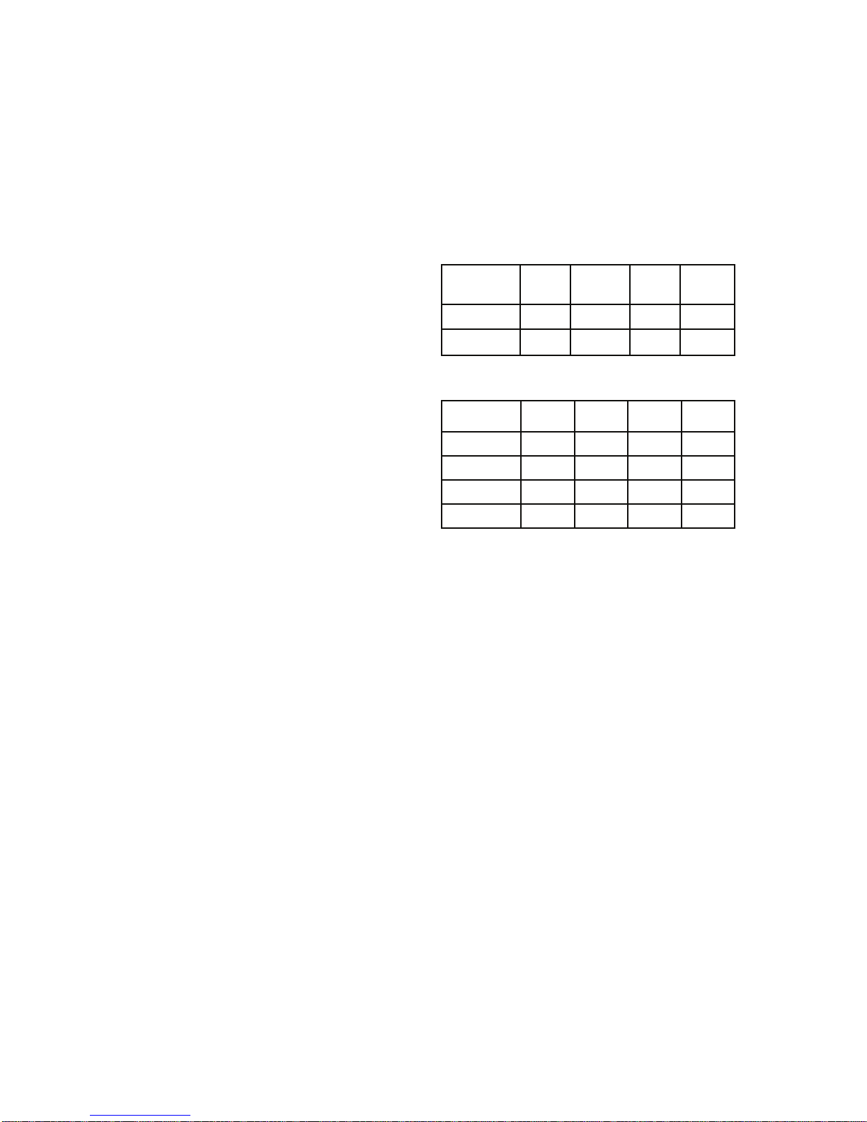
2.4.1 Heaters installed within the
heated space
Where heaters are installed within the heated
space (i.e. not a plant room , or enclosure )
then
Combustion air or heater related ventilation
air will not be required if -
The heaters are installed in room
sealed mode (ie with a positive
connection to atmosphere of both flue
and combustion air)
OR
If the design air change rate of the
heated space is 0.5 air changes per
hour or greater
The design air change rate may be satisfied
by natural infiltration or by mechanical
ventilation.
Combustion air ventilation
will be required if
The heater(s) are installed with flue
only (ie without the positive connection
to atmosphere of a combustion air
duct)
And
The design air change rate of the
heated space is less than 0.5 air
changes per hour
Where heater(s) are installed without the
positive connection of combustion ductwork
within a heated space where air change rate
of that heated space is less than 0.5 air
changes per hour then it will be necessary to
provide either natural ventilation openings to
the heated space (Section 2.4.1.1 refers)
or the mechanical ventilation of the heated
space (Section 2.4.1.2 refers)
2.4.1.1
Natural Ventilation Openings to the
Heated Space
If the heater(s) are to be installed without the
positive connection of combustion air
ductwork within a heated space, and where
MODEL
Minimum Free Area Of
Ventilation Opening
High Level Low Level
cm2 cm2
250 None 158
330 None 211
410 None 263
490 None 315
the design air change rate of that heated
space is less than 0.5 air changes per hour,
then provision for low level natural ventilation
openings only will be necessary.
The minimum free area of the low level
natural ventilation opening shall be
2 cm
2
for each kW of rated heat input
The low level natural ventilation opening
should be situated on an external wall and be
within 1000 mm of floor level for natural gas
and ideally at floor level for lpg gas
installations but in any event no higher than
250 mm.
The table below provides specific data for
each heater model as -
2.4.1.2 Mechanical Ventilation to the
Heated Space
In the event that the heater(s) are to be
installed without the positive connection of
combustion ductwork within a heated space
and where that heated space has a design
air change of less than 0.5 air changes per
hour and that the installer prefers to
mechanically ventilate the heated space
rather than provide ventilation openings then
-
The heated space needs to be
mechanically ventilated so that the
design air change is 0.5 air changes
per hour or greater.
It is a requirement that the mechanical
ventilation shall be of the !input! Type
with either natural or mechanical
extraction
Systems of mechanical extraction with
a natural inlet shall not be used
It is necessary to provide an automatic
means to safely inhibit heater(s)
operation should mechanical air supply
fail for any reason
2.4.2 Heaters Installed within a Plant
Room or Enclosure
A plant room means a room housing the
heater plant and probably other items of
building service plant and would generally
have generous space for maintenance
An enclosure is where the heater is installed
within a compartment or confined area where
space is limited
Where heaters are installed within a plant
room or enclosure then provision for both
combustion air and / or air for general
ventilation will be required by means of high
MODEL
Minimum Free Area Of
Ventilation Opening
High Level Low Level
cm2 cm2
250 394 394
330 527 527
410 656 656
490 787 787
MODEL
Minimum Free Area Of
Ventilation Opening
High Level Low Level
cm2 cm2
250 158 316
330 211 422
410 263 525
490 315 630

and low level ventilation openings (sections
2.4.2.1 and 2.4.2.2 refer to plant room
applications and sections 2.4.2.3 and 2.4.2.4
refer to enclosure applications).
Alternatively the plant room or enclosure may
be mechanically ventilated (section 2.4.2.5
refers)
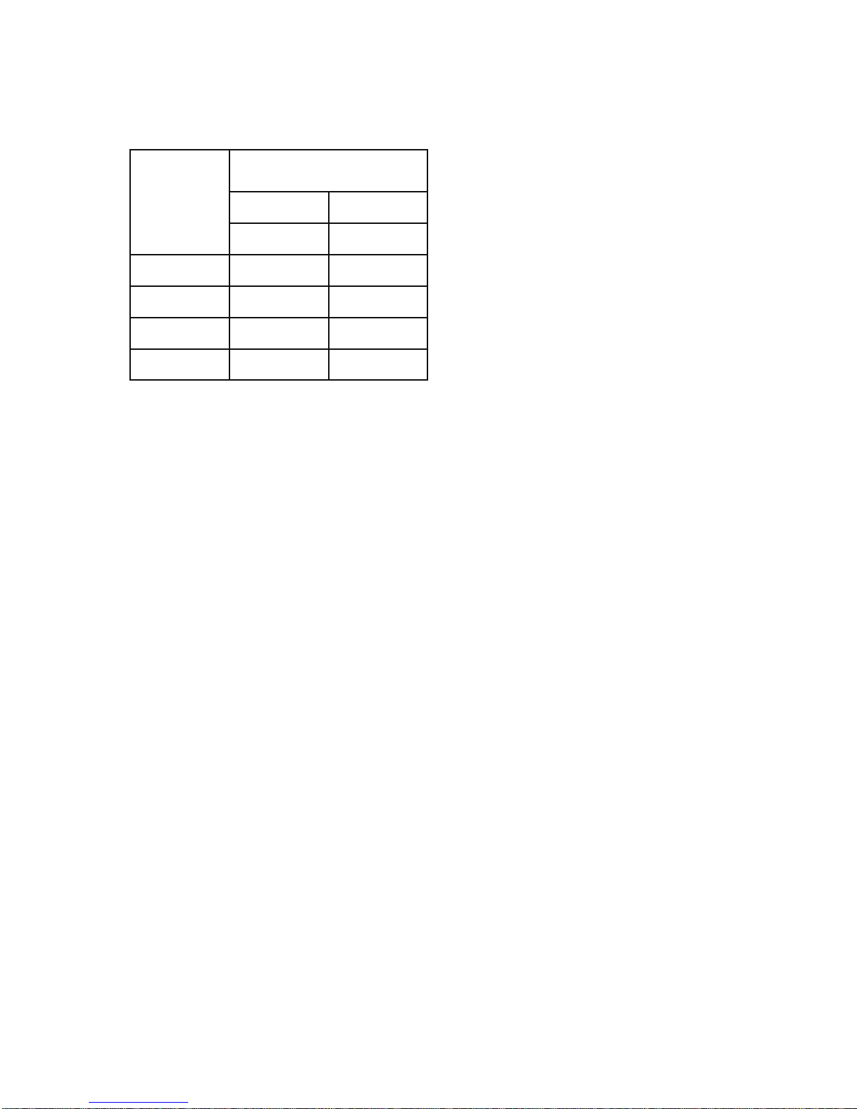
2.4.2.1 Natural Ventilation Openings to
Plant Rooms for Room Sealed Heaters
For plant room applications the minimum free
area of ventilation opening will depend upon
whether the heater(s) is installed in room
sealed mode (ie with a positive connection to
atmosphere of both flue and combustion air)
Or with flue only (ie without the positive
connection to atmosphere of a combustion
air duct)
Where the heater(s) is installed in a plant
room and in room sealed mode (ie with a
positive connection to atmosphere of both
flue and combustion air ) the minimum free
area of ventilation opening needs to be
At high level 5 cm
2
for each kW of
rated heat input
At low level 5 cm
2
for each kW of rated
heat input
The high level ventilation opening should be
sited on an external wall and positioned as
high as is practical and always within the top
15% of the wall height
The low level natural ventilation opening
should be situated on an external wall and be
within 1000 mm of floor level for natural gas
and ideally at floor level for l.p.g gas
installations but in any event no higher than
250 mm.
The table below provides specific data for
each heater model as -
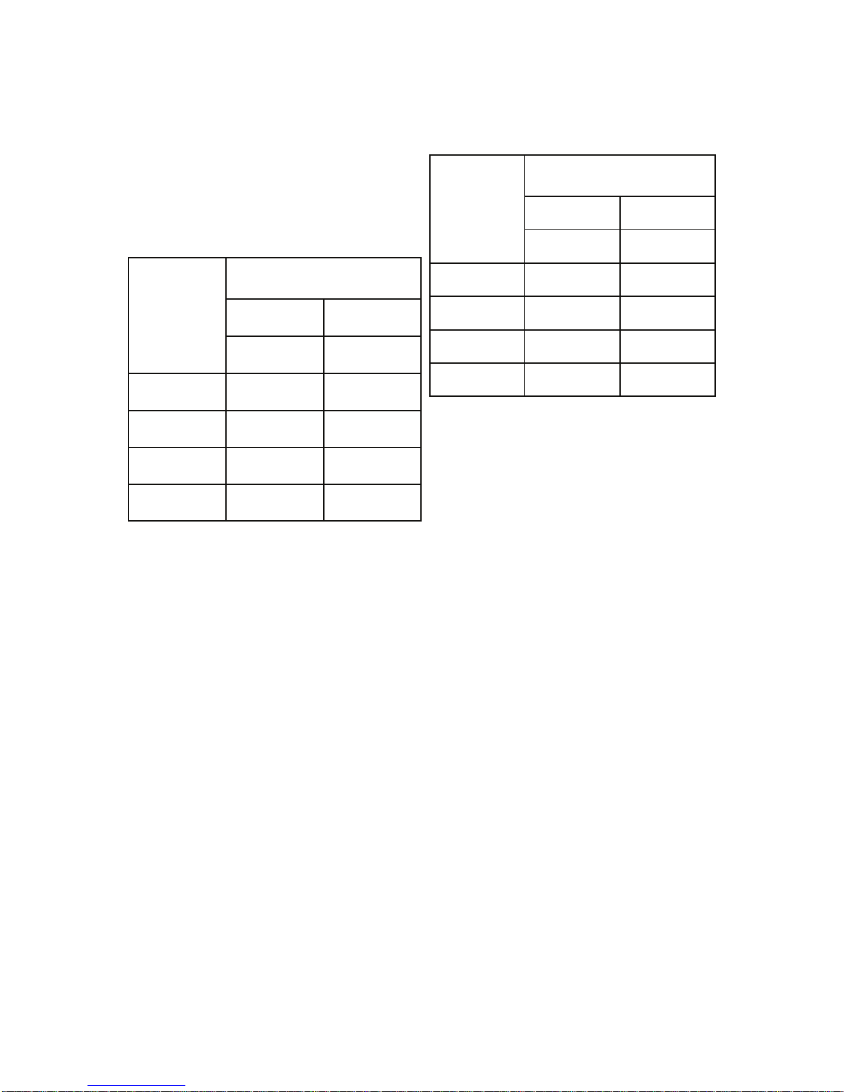
2.4.2.2 Natural Ventilation Openings to
Plant Rooms for Flued Heaters
Where the heater(s) is installed in a plant
room and in flue mode (ie without a positive
connection to atmosphere of combustion air
ductwork ) the minimum free area of
ventilation opening needs to be
At high level 2 cm
2
for each kW of
rated heat input
At low level 4 cm
2
for each kW of rated
heat input
The high level ventilation opening should be
sited on an external wall and positioned as
high as is practical and always within the top
15% of the wall height
The low level natural ventilation opening
should be situated on an external wall and be
within 1000 mm of floor level for natural gas
and ideally at floor level for l.p.g gas
installations but in any event no higher than
MODEL
Minimum Free Area Of
Ventilation Opening
High Level Low Level
cm2 cm2
250 394 394
330 527 527
410 656 656
490 787 787
MODEL
Minimum Free Area Of
Ventilation Opening
High Level Low Level
cm2 cm2
250 394 788
330 527 1053
410 656 1312
490 787 1574
250 mm.
The table below provides specific data for
each heater model as -
2.4.2.3 Natural Ventilation Openings to
Enclosures for Room Sealed Heaters
For enclosure applications the minimum free
area of ventilation opening will also depend
upon whether the heater(s) is installed in
room sealed mode (ie with a positive
connection to atmosphere of both flue and
combustion air)
Or with flue only (ie without the positive
connection to atmosphere of a combustion
air duct)
Where the heater(s) is installed in a plant
room and in room sealed mode (ie with a
positive connection to atmosphere of both
flue and combustion air ) the minimum free
area of ventilation opening needs to be
At high level 5 cm
2
for each kW of
rated heat input
At low level 5 cm
2
for each kW of rated
heat input
The high level ventilation opening should be
sited on an external wall and positioned as
high as is practical and always within the top
15% of the wall height
The low level natural ventilation opening
should be situated on an external wall and be
within 1000 mm of floor level for natural gas
and ideally at floor level for l.p.g gas
installations but in any event no higher than
250 mm.
The table below provides specific data for
each heater model as -
2.4.2.4 Natural Ventilation Openings to
Enclosures for Flued Heaters
Where the heater(s) is in an enclosure and in
flue only mode (ie without a positive
connection to atmosphere of combustion air
ductwork ) the minimum free area of
ventilation opening needs to be
At high level 5 cm
2
for each kW of
rated heat input
At low level 10 cm
2
for each kW of
rated heat input
The high level ventilation opening should be
sited on an external wall and positioned as
high as is practical and always within the top
15% of the wall height
The low level natural ventilation opening
should be situated on an external wall and be
within 1000 mm of floor level for natural gas
and ideally at floor level for l.p.g gas
installations but in any event no higher than
250 mm.
The table below provides specific data for
each heater model as -
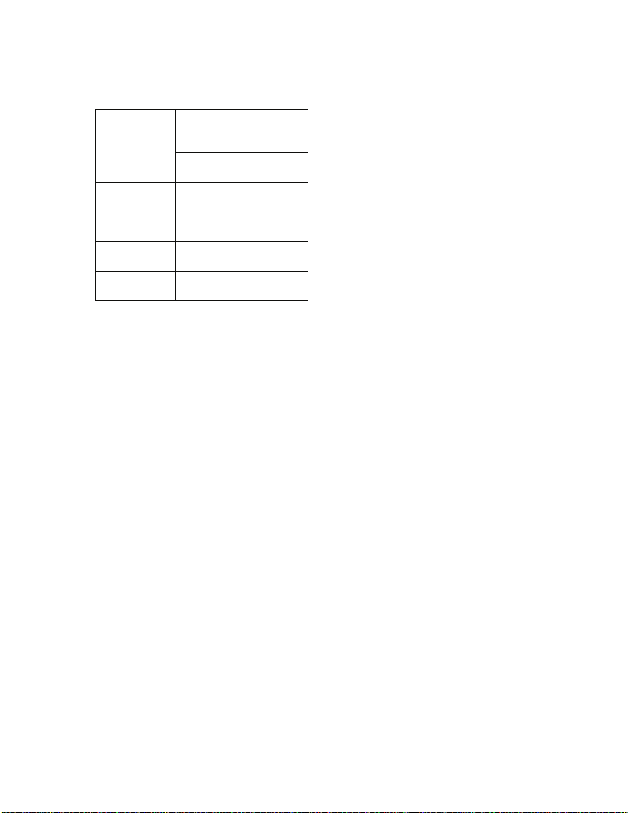
2.4.2.5 Mechanical Ventilation to a
Plant Room or Enclosure
In the event that the installer prefers to
mechanically ventilate the plant room or
enclosure rather than provide ventilation
openings then -
The plant room or enclosure needs to
be mechanically ventilated at the rate
of 4.14 m
3
/h of fresh air per kW or
rated heat input.
It is a requirement that the mechanical
Mechanical Ventilation
Rate for Plant Room or
Enclosure
M3/h
250
327
330
436
410
543
490
652
MODEL

Provision for the disconnection of the flue for
servicing and inspection purposes must also
be made.
The position of the flue and its terminal
should be such that it does not impair the
combustion process. It should terminate in
an exposed position so as to allow the free
escape of flue gases without risk of their reentering the building through windows,
ventilation ports etc.
The following distances in mm’s should
be observed
200
below guttering or eaves
300
from corners or openings (windows
doors etc) and from other horizontal
terminals on same wall
1200
from a facing surface
1500
from another terminal vertically on the
same wall
2000
from ground level
The heaters must be connected to the flue
system supplied by Benson Heating and be
capable of withstanding the stresses and
loadings associated with normal use.
When designing the flue system the
prevention of the formation and entrapment
of condensation must be a key consideration.
Horizontal flue should be fitted ensuring a
slight gradient approx 2
0
towards the terminal
Where condensation is unavoidable traps
should be included to encourage the
condensates to flow freely to a point from
which they may be released, preferably into
a gully.
The condensate pipe from the flue to the
disposal point must be made from corrosion
resistant pipe of not less than 25mm internal
diameter.
If the flue passes through a wall, ceiling, or
roof made from combustible material then it
has to be sleeved so as to provide a
minimum of a 25mm void between the
exterior of the flue and the internal wall of the
sleeve.

C32 Vertical Co axial flue Kit options
L1 maximum combined flue length 10 metres
Coaxial Terminal
Extra pipes to extend the flue are available as an option
Pipe Ø 130 x 1000 mm
Pipe Ø 130 x 500 mm
Pipe Ø 130 x 250 mm
Bend
Ø 130 x 45
0
Bend Ø 130 x 900
Part No
33-55-207
33-54-201
33-54-202
33-54-203
33-54-204
33-54-205
Option C
12
Not Illustrated Contact Benson Technical Dept
In this configuration the heater is connected to a horizontal flue system discharging the
products of combustion and bringing in the combustion air from outside the building in
which the heater is located.
The outlet / inlet must be through the wall and may be made with two separate pipes or
with a horizontal coaxial concentric terminal.
Not always practical in the Bi Directional configuration.

Option B22
In this configuration the heater is connected to a single flue pipe to discharge the products
of combustion outside the building either through the roof or through a wall. The air for
combustion is taken from inside the building.
L1 maximum flue length 10 metres
Universal Terminal
Extra pipes to extend the flue are available as an option
Pipe Ø 130 x 1000 mm
Pipe Ø 130 x 500 mm
Pipe Ø 130 x 250 mm
Bend
Ø 130 x 45
0
Bend Ø 130 x 900
Part No
33-54-207
33-54-201
33-54-202
33-54-203
33-54-204
33-54-205
Heater Unit Flue Exit HORIZONTAL Flue Exit VERTICAL
MIN. MAX. MIN. MAX.
250 m 1,00 8,00 1,00 10,00
330 m 1,00 8,00 1,00 10,00
410 m 1,00 8,00 1,00 10,00
490 m 1,00 8,00 1,00 10,00

Caution
It is imperative that the flue should be
properly sealed where it passes through the
roof, this can best be achieved by using the
approved method of roof flashing plate and
cravat. The flue spigot outlet on all Variante
heaters is in horizontal configuration.
Note
It should be noted that claims made under
warranty and attributed to the ingress of
water may not be considered especially if an
approved method of sealing has not been
used, or if the design of the flue has not
made provision for possible condensation
problems.
It is also recommended that BS5854: 1980
and BS5440: parts 1 and 2 are used as a
consultative document when considering flue
requirements.
If terminating through a wall only use Benson
approved horizontal terminals
2.6 Electrical Installation
All electrical
wiring and
connections
must be in
accordance with
the relevant
European,
National, and
Local
regulations as
well as to IEE
Standards.
Ensure that the Electric and Gas supplies are
turned off before any electrical work is
carried out on the heater.
Also ensure that
wiring cannot
make contact
with any metal
surfaces liable
to be subject to
high
temperatures,
and where
insulation of the
wiring could be
impaired as a
result of such
contact.
All Variante models must be earthed.
Warning

Ensure that the
electrical
supply is
compatible to
the heater.
ALL HEATERS
ARE
NEUTRALLY
RESET
Caution
The main electrical supply must not be
switched off or disconnected as a method for
stopping the heater, the exception to this is in
the event of an emergency, or when the
heater has been allowed to cool sufficiently
to prevent any damage from being sustained
to the heater or its controls (ie: during
servicing).
Claims for damage will not be considered if
they have resulted from incorrect wiring or
the incorrect use of the heater
Each heater requires a permanent 230V
50Hz 1ph electrical supply, which must be
wired through a fused isolator fitted with a
fuse of the correct rating (see section 7.1).
The correct supply connection points for the
live, neutral, and earth.
Wiring diagrams are also detailed within this
manual, (section 6.0 )
The electrical supply isolator should be
mounted adjacent to the air heater in an
easily accessible position to allow for
servicing isolation, or emergency shut off.
Electrical panel
Warning
Ensure that the mains isolator is turned OFF
before undertaking any electrical work on the
heater. Access to the electrical panel is
gained by opening the right hand heater side
panel.
Warning
Ensure that all connections are secure and
that there are no loose strands which could
bridge across the terminals.
A minimum conductor size of 1.0 mm
(diameter) is required.
Caution
When using
CP4 Optimised
Controller
Consideration
should be made
when routing
the cable
between the
control and
heater . Avoiding
where possible
any existing
cables and

switch gear as
any induced
voltage may
affect the
operation of the
sequential
control box
within the
heater.
It is
recommended
that screened
cable is used
when the
control is to be
sited more
than 10 metres
away from the
heater
One electrical
panel per heater
is required,
unless heaters
are specified for
multiple heater
control
applications. On
no account
should more
than one heater
be connected to
a single time
switch or
thermostat.
The only

exception to this
is when a
control panel
suitable for
multiple heater
applications is
supplied by the
manufacturer.
Any ancillary electrical items e.g. room
thermostats , time switches, remote panels
etc, must be wired into the heater electrical
circuit in accordance with the diagrams
provided
Note
When external controls operate to switch the
heater OFF, power to the heater should
remain to allow the fan to continue to operate
to sufficiently cool the heater thereby
preventing damage to the heat exchanger.
Fan limit control
( Situated inside the right hand side panel)
FAN ON 50
c
FAN OFF 30c
These settings may require slight adjustment
on commissioning
Fan control (white button)
The fan control switch features normally open
230V contacts, and is wired to control the live
supply to the fan motor . When the circuit is
made, the fan will switch on when the heat
anticipator has closed the fan switch contacts.
When the thermostat or time switch shuts
down the burner, the fan will continue to run
until the thermal switch has cooled sufficiently
to prevent the residual heat from damaging
the heater or its controls.
On start up the fan delay prevents air being
circulated until the desired temperature is
achieved
Limit control (red button) SET at 100
c
An adjustable high temperature manual reset
limit control. If this control needs resetting the
cause should be determined and rectified
immediately.
On models with two fans a second limit
control is situated inside the right side panel
and is wired in series. Operation of either
switch will shut down the heater. On larger
models there will be additional limit stats fitted
Caution
The power supply to the fan must not be
interrupted, the only time when power supply
can be disconnected or interrupted is during
servicing or in emergencies
If there is a requirement for the heater to be
switched off over night then the gas valve
circuit should be opened via a time switch,
etc, as per the wiring instructions and
diagrams supplied within section 6.0 of this
manual.
2.7 Gas installation
Warning
Please read notice on page 3 of this
manual
As there have been recorded instances of the
deposition of copper sulphide dust within the
valves and orifices of gas appliances as a
direct result of a reaction between the
hydrogen sulphide contained in some natural
gasses and copper pipe we recommend that
the heater(s) should not be connected to any
natural gas pipe distribution system which
utilizes copper pipework, including final
connections. Instead steel pipework should
be used throughout.
In the event that it is impractical to use steel
pipework or where installers are obliged or
insist on using elements of copper pipework
within the installation then we strongly
recommend that the gas supplier be
consulted as specific conditions and
requirements may be necessary.
The Variante range of heaters are all
manufactured and pre set for use with Natural
Gas,or Lpg and all feature a 3/4” BSP
connection point. Prior to installation the
supply characteristics (gas type and pressure)
must be checked to ensure that they are in
accordance with the data plate on the heater.

The gas
supplier should
check that the
meter and
service
connection to
the heater are
capable of
delivering the
required volume
of gas, thereby
ensuring that
the minimum
burner pressure
can be
achieved.
Consideration
should be given
to the
pressure drop
on single and
multi heater
installations and
the effect they
may have on
other plant
sharing the
supply.
If it is necessary to fit a gas pressure
booster, the controls must include a low
pressure cut off switch which must be fitted
on the supply / inlet side of the booster. It is
also a requirement that the gas supplier is
advised prior to the installation or fitting of
the booster.
Each heater supply must be fitted with a
separate isolating cock positioned adjacent
to and upstream of the union which must be
sited outside the heater.
The isolating cock should be of the 90
0
turn
type and should be clearly marked OPEN /
CLOSED it should also be installed so as to
fall to the closed position
An approved gas jointing compound must be
used on all joints and unions and the system
purged and tested for soundness prior to
final connection
The connection to the heater can be made
by way of either an approved flexible
coupling or rigid connection . Threaded
connections must comply to ISO 288/1 or
ISO 7/1 further information concerning
accepted European practice is detailed in
BS EN1020 1998.
The diameter of the pipework from the
isolating cock to the burner must not be less

than the diameter of the connection into the
multiblock.
Note
Reference to The Institute of Gas Engineers
publications Utilisation Procedures IGE/UP1
and IGE/UP2 together with reference to
BS6891 is strongly advised.
3.0 Commissioning
Note
It is a requirement that only suitably
qualified and competent personnel are
allowed to undertake the commissioning
of the heater.
It is also strongly recommended that prior
to commissioning the engineers
familiarises themselves with the heater.
the specific requirements of the
installation / application, and the
information contained within the manual.
Warning
All heaters are subject to a rigorous test
programme prior to despatch, whilst such a
programme does involve pre-commissioning
and the setting of the heater to operate
efficiently and within its designed operational
limits this does not mean that the function of
thorough on site commissioning is less
important
It is strongly recommended that the
equipment used for the sampling and
analysis of the flue gases is accurate to
within +/- 0.1% and maintained so that it is
regularly calibrated.
The following
pre-
commissioning
checks should
be undertaken,
having first
ensured that the
gas and
electrical
supplies are
turned off.
(a) Check that all panels and fasteners are
secure and in place.
(b) Check that the heater is mounted safely.
(c) Check that the flue is sealed, secured,
and adequately supported.
(d) Check that the fan is free to rotate, that
the fan is secured to its shaft, and that the
guards and fan assembly are all in place and
properly secured.
(e) Check that the heater is installed so that
it is not tilted and remains square.
(f) Check that the outlet louvres (Axial
heaters) are set to offer minimum resistance
to air flow.
3.1 Electrical pre-tests
The electrical safety checks must include the
following
a) Test for earth continuity
b) Test for resistance to earth
c) Check live and neutral connections are
correct.
d) Check to ensure that when the external
controls operate to switch the heater off,
power remains to the fan
3.2 Gas supply pre-test
Ensure that the service pipework has been
installed purged and tested in accordance

Fault Finding
Gas Supply
ON
Burner
fails to
li
g
ht
Turn on Gas
Supply
Electric
Supply ON
Turn on Electric
Supply
Air in Gas
Supply
Purge Gas Line
Thermostat
calling for
heat
Limit thermostat
operated
No
Yes
Rese t Li mi t
thermostat
Air pressure
switch made
Check flue fan
connections
Flue fan running
Yes
Replace flue fan
Check flue is
clear
Change air
pressure switch
Yes
Spark ignition
on
Check HT leads
and
connections
No flame
Faulty control
box
No
Change gas
valve
Faulty G a s
valve
No
No
No
Yes
Yes
Yes
Yes
Yes
Yes
Yes
Yes
No
Yes
YesYes
Yes
Check fuse Replace if
required

Fault finding cont’d
Fan will
not run
heater
goes off
on limit
No
Bad
electrical
connection
Yes
Check
wiring
connection
Reset fan
control
settin
g
s
Fan runs in
manual
mode
Fan control
settings
incorrect
Yes
Yes
Yes
Yes
Yes
No
No
Faulty fan
control
Faulty fan
motor or
ca
p
acitor
Change fan
control
Change fan
motor or
ca
p
acitor

Wiring Diagrams VR 250-330 Auto Ignition
WARNING NEUTRAL RESET
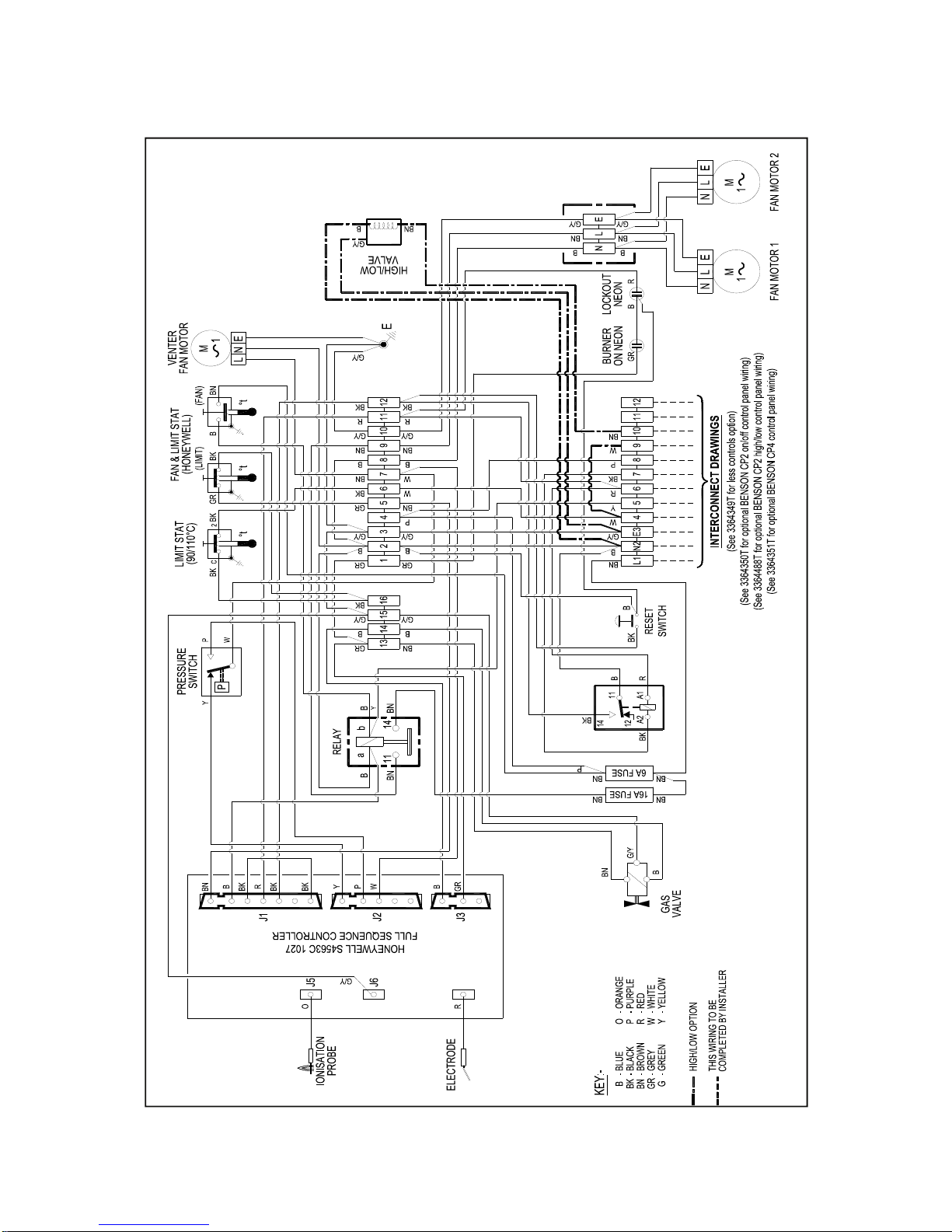
Wiring Diagram VRBD 410- Auto Ignition
WARNING NEUTRAL RESET

TBA
Wiring Diagram VRBD 490- Auto Ignition

Wiring Connection CP2 On/Off 33-64-350T
Wiring Connection CP2 Hi/Lo 33-64-488T
WARNING NEUTRAL RESET
WARNING NEUTRAL RESET
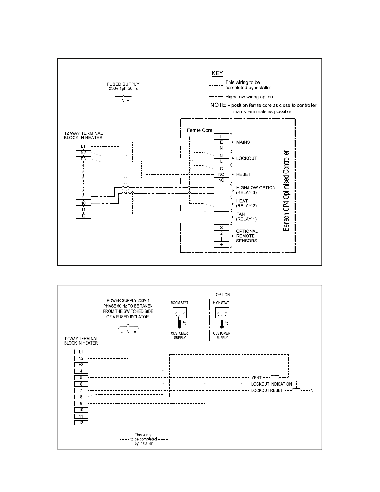
CP4 Controller Connections 33-64-351T
Less Controls Connections 33-64-349T
WARNING NEUTRAL RESET
WARNING NEUTRAL RESET
7.1 Technical Data Common Information
Appliance Type B
22 C 32 C12
PIN / report no 0063BQ5461
Electrical Supply 230V 50Hz 1ph
Fuse Rating 6 AMP
IP Rating IP20
Fan Limit Settings Fan On 50ºC Fan Off 30ºC Limit 100ºC
Country Approved Gas Category
AT,CH,CZ,DK,EE,ES,FI,GB,GR,HU,IE,IT
IS,LT,LV,NO,PT,RO,SE,SI,SK,TR
I2H
BE,CZ,NL,FR,DE,IE,IT,ES,CH,PT,GB,SE,
SK,SL,PT,PL,TR
I3P
PL,LU,DE,RO
I2E
PL
I
2LS
PL
I
2LW

Natural Gas (G20 I2H) Tubular Heater
The minimum allowable pre-purge time requires calculating [BS EN1020:1998 clause 6.38].
To do this only the Carbon Dioxide CO
2
figure needs to be measured.
E.G. on a model 250 the calculated minimum time is = 286.2/ ((100 / CO2) + 1)
If the measured CO
2
is 6.7%
Then 100 / 6.7 = 14.9
14.9 + 1 = 15.9
Therefore minimum pre-purge time is = 286.2 / 15.9 = 18.0 seconds
The calculation to be conducted is given below for all models:
Model 250 Minimum pre-purge time = 286.2 / ((100 / CO2) + 1)
Model 330 Minimum pre-purge time = 269.7 / ((100 / CO2) + 1)
Model 410 Minimum pre-purge time = 261.4 / ((100 / CO2) + 1)
Model 490 Minimum pre-purge time = 269.2 / ((100 / CO2) + 1)
The pre-purge time must then be measured. If the measured pre-purge time is lower
than the calculated time STOP and contact Benson Heating.

Propane (G31 I3P) Tubular Heater
The minimum allowable pre-purge time requires calculating [BS EN1020:1998 clause 6.38].
To do this only the Carbon Dioxide CO
2
figure needs to be measured.
E.G. on a model 250 the calculated minimum time is = 724.7 / ((300 / CO2) + 2.01)
If the measured CO
2
is 8.0%
Then 300 / 8.0 = 37.5
37.5 + 2.01 = 39.51
Therefore minimum pre-purge time is = 724.7 / 39.51 = 18.3 seconds
The calculation to be conducted is given below for all models:
Model 250 Minimum pre-purge time = 724.7 / ((300 / CO2) + 2.01)
Model 330 Minimum pre-purge time = 682.8 / ((300 / CO2) + 2.01)
Model 410 Minimum pre-purge time = 661.7 / ((300 / CO2) + 2.01)
Model 490 Minimum pre-purge time = 681.6 / ((300 / CO2) + 2.01)
The pre-purge time must then be measured. If the measured pre-purge time is lower
than the calculated time STOP and contact Benson Heating.

NAT GAS / LPG MODEL 250 330 410 490
HEAT
OUTPUT
kW
Btu
72.0
246,000
96.0
328.000
120.0
409,000
144.0
491,000
HEAT INPUT
(Nett)
kW
Btu
78.8
268,900
105.2
359,000
130.4
445,000
156.5
534,000
EFFICIENCY % Nett 91.4 91.2 91.5 91.5
EFFICIENCY % Gross 82.3 82.1 82.4 82.4
HEAT
OUTPUT Low Fire
kW
Btu
46.6
159,000
62.2
212.250
77.5
264,430
93.0
317,300
HEAT INPUT
(Nett) Low Fire
kW
Btu
50.7
173,000
67.6
230,720
83.8
286,000
100.6
343,200
GAS CONNECTION BSP/Rc
3/4”
3/4” 3/4” 3/4”
MIN INLET
PRESS NAT GAS
mbar
Ins WG
17.5
7
17.5
7
17.5
7
17.5
7
BURNER
PRESSURE NAT GAS
mbar
Ins WG
8.7
3.5
8.7
3.5
9.2
3.7
9.2
3.7
BURNER PRESSURE
NAT GAS Hi Lo
Hi mbar
Lo mbar
8.7
3..5
8.7
3.5
9.2
3.8
9.2
3.8
MAIN INJECTOR
NATURAL GAS
mm
No Off
3.4
6
3.4
8
3.4
10
3.4
12
NAT GAS
CONSUMPTION
ft3/hr
m
3
/hr
294
8.33
393
11.12
490
13.87
587
16.63
MIN INLET
PRESS LPG
Mbar
Ins WG
37.0
14.8
37.0
14.8
37.0
14.8
37.0
14.8
BURNER
PRESSURE LPG
Mbar
Ins WG
25.5
10.2
25.5
10.2
25.5
10.2
25.5
10.2
LPG PROPANE
CONSUMPTION
m3/hr
Kg/h
3.21
5.94
4.28
7.92
5.34
9.88
6.41
11.86
MAIN INJECTOR
PROPANE GAS
Mm
No Off
2.0
6
2.0
8
2.0
10
2.0
12
TEMPERATURE
RISE
ºC
ºF
32
58
34
61
32
58
32
58
AIR
FLOW
ft3/min
m
3
/sec
4026
1.90
4789
2.26
6527
3.08
8010
3.78
VRABD
THROW
ft
mtrs
203
62
210
64
249
76
256
78
FAN STATIC
PRESSURE
Pa
Ins WG
150
0.60
180
0.72
200
0.80
200
0.80
SOUND LEVEL @ 3m Dba 61 63 66 66
FLUE DIAMETER * mm 130 130 130 130
COMBUSTION AIR DIA mm 130 130 130 130
SUPPLY VOLTAGE Axial 230/1/50 230/1/50 230/1/50 230/1/50
ELECTRICAL POWER(AMPERES) Axial 2.8 4.2 4.8 5.8
INTERNAL FUSE
RATING AMPERES
VRA 6 6 6 6
POWER ABSORPTION Kw Axial 0.56 0.88 0.95 1.2
MOUNTING HEIGHT
(MTRS)
Min
Max
2.4
3.5
2.4
3.5
2.4
3.5
2.4
3.5
GROSS FLUE TEMP ºC 150 150 160 160
WEIGHT Kgs Axial 181 203 242 279
AIR PRESS SWITCH mbar 1.65 1.65 1.65 1.65
FLUE
RESISTANCE
min mbar
max mbar
-0.2
+0.4
-0.2
+0.4
-0.2
+0.4
-0.2
+0.4
7.2 Technical Data

MODEL 250 330 410 490
Fan Plenum Axial 33-64-585 33-64-586 33-64-587 33-64-588
Fan Axial VRA Standard 28-09-062 28-09-092 28-09-056 28-09-098
Fan Limit Stat 28-60-021 28-60-021 28-60-021 28-60-021
Gas Valve 28-30-181 28-30-181 28-30-184 28-30-184
Control Box 29-01-183 29-01-183 29-01-183 29-01-183
Injector Natural Gas 33-64-145 33-64-145 33-64-145 33-64-145
Injector LPG Propane 33-64-147 33-64-147 33-64-147 33-64-147
Inshot 33-64-160 33-64-160 33-64-160 33-64-160
Gas Manifold 33-64-017 33-64-018 33-64-153 33-64-154
Air Pressure Switch 28-40-139 28-40-139 28-40-139 28-40-139
Flue Fan 28-09-089 28-09-089 28-09-090 28-09-090
Run Neon Green 28-50-038 28-50-038 28-50-038 28-50-038
Lockout Neon Red 28-50-030 28-50-030 28-50-030 28-50-030
Overheat Thermostat 28-60-039 28-60-039 28-60-039 28-60-039
Electrode 33-64-193 33-64-193 33-64-193 33-64-193
Ionisation Probe 33-64-194 33-64-194 33-64-194 33-64-194
Fuse Holder 28-07-050 28-07-050 28-07-050 28-07-050
Fuse 28-07-048 28-07-048 28-07-048 28-07-048
Reset Switch 28-40-141 28-40-141 28-40-141 28-40-141
Reset Relay 230 Volt 28-25-039 28-25-039 28-25-039 28-25-039
Optimised Control B-CP4 B-CP4 B-CP4 B-CP4
8.0 Parts list

V2RABD

Heater A B C D E F G H J K
250- 490
225 85 330 900 1630 1860 210 200 130 130
Vertical Co/Axial Terminal Dimensions
Dimensions in mm’s
AIR FLUE
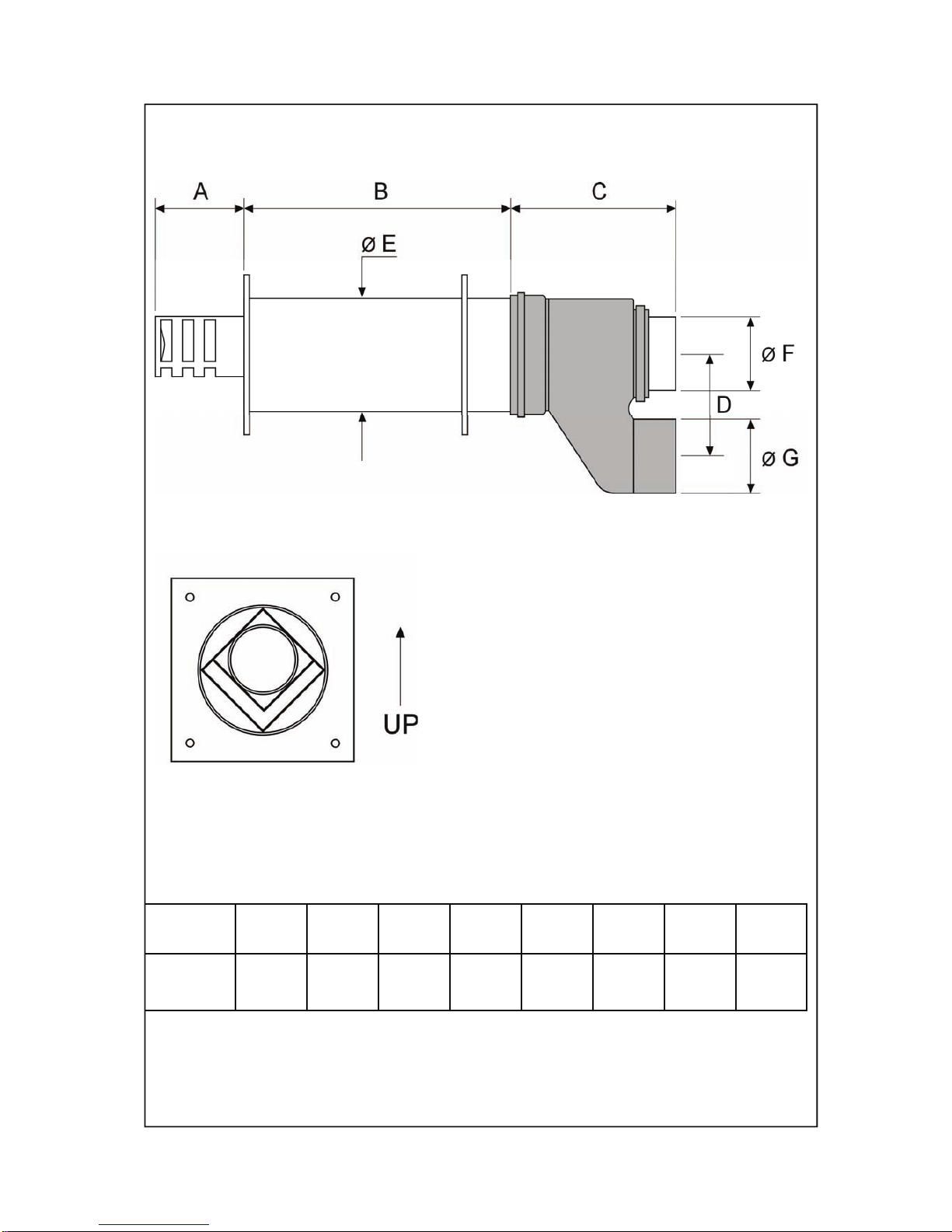
Heater A B C D E F G B+C
250-490
180 420 340 225 200 130 130 750
Horizontal Co/Axial Terminal Dimensions
Ensure Terminal is located on the wall
in this configuration
TOP
BOTTOM
Dimensions in mm’s
AIR
FLUE

BENSON HEATING
LUDLOW ROAD
KNIGHTON
POWYS
LD7 1LP
Telephone +44 (0) 1547 528534
Facsimile +44 (0) 1547 520399
email information@bensonheating.co.uk
Web www.bensonheating.com
 Loading...