

Page 1

Place your message here. For m a xi m u m im pa ct, use two or three sentences.
Headin
g
BENSON GUHA/GUHC
RANGE
(NATURAL GAS FIRED UNIT HEATER)
I N S T A L L A T I O N C O M M I S S I O N I N G
S E R V I C I N G
U S E R I N S T R U C T I O N S
Issue 5
March 2005
Page 2

~ C O N T E N T S ~
S E C T I O N A
1.0 Compliance Notices
1.1 Certificates of Conformity
1.2 General Product Information
1.3 General Requirements
1.4 Delivery & Pre-installation Checks
1.5 Warranty
2.0 Installation
2.1 Installation Clearances and Mounting Heights
2.2 Heater Mounting
2.3 Warm Air Circulation
2.4 Air Supply
2.5 Flue Installation
2.6 Electrical Installation
2.7 Electrical Panel
2.8 Time Switch
2.9 Room Thermostat
2.10 Fan and Limit Controls
2.11 Summer / Ventilation Switch
2.12 Gas Installation
3.0 Commissioning
3.1 Electrical Pre-Tests
3.2 Gas Supply Pre-Tests
3.3 Ignition Sequence Manual Versions
3.4 Ignition Sequence Automatic Versions
3.5 Hand Over
4.0 Servicing
4.1 Servicing Procedure
5.0 Fault Diagnosis by Flow Charts
6.0 Wiring Diagrams
7.0 Technical Data Formulae
7.1 Technical Data Common Information
7.2 Technical Data Heater Information
8.0 Reference Information
9.0 Parts Listing
Page 3

S E C T I O N B
Warranty Registration
Updated Information
Timer Information Manual
S E C T I O N C
10.0 Introduction
10.1 Commissioning / Hand over
10.2 Servicing
10.3 Start up Procedure
10.4 Start up Procedure Automatic Versions
10.5 Stop Procedure Manual / Automatic Versions
10.6 Shut Down Procedure
10.7 Fail-safe Situations
10.8 Contact Information
I L L U S T R A T I O N S
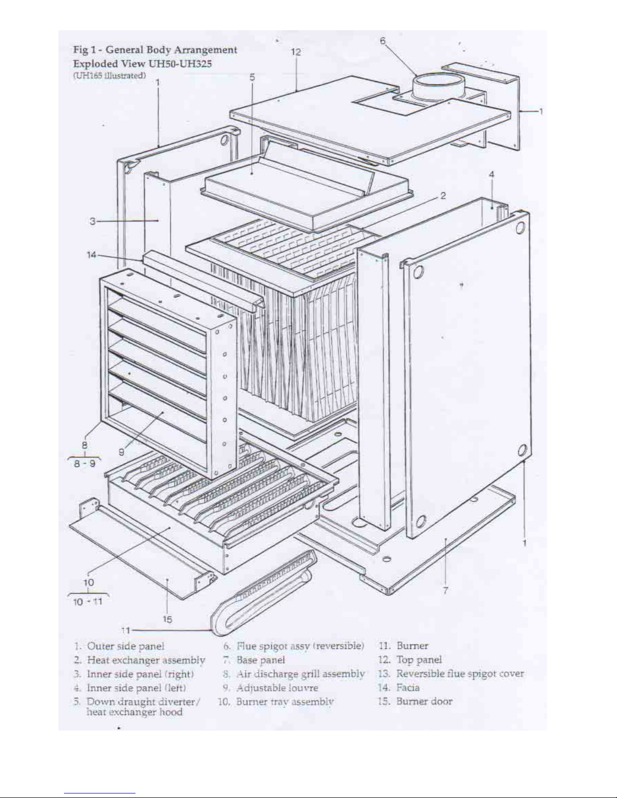
Exploded view
Flue Systems
Gas Train & Pilot Installation
Electrical installation
Axial & Centrifugal Fans
Fault Diagnosis Flow Charts
Electrical Drawings
IMPORTANT NOTICE TO INSTALLERS
Installers should satisfy themselves that the gas pipework installation is carried out
in accordance with all current legislation, Codes of Practice and recommendations .
Additionally it may be necessary to protect the gas valves which form part of the
heater or burner assembly from potential pipe contamination particularly, but not
exclusively , where copper gas pipework is used.
In instances where copper pipework is to be used for all or part of a gas pipework
installation, including short length final connections then we advise that installers
consult with gas supplier or provider and satisfy themselves what additional
precautions may be necessary
Any reference made to Laws, Standards, Directives , Codes of Practice or other
recommendations governing the application and installation of heating appliances and
which may be referred to in Brochures, Specifications, Quotations, and Installation,
Operation and Maintenance manuals is done so for information and guidance purposes only
and should only be considered valid at the time of the publication. Benson Heating cannot
be held responsible from any matters arising from the revision to or introduction of new
Laws, Standards, Directives, Codes of Practice or other recommendations.
Page 4

1.0 Compliance notices
The Benson GUH range of warm air heaters
detailed herewith are manufactured by
Benson Heating within a strictly controlled
environment within the parameters of
ISO9001
These instructions are only valid if the
following country code is on the appliance
GB. IE. If this code is not present on the
appliance, it is necessary to refer to the
technical instructions which will provide the
necessary information concerning the
modification of then appliance to the
conditions of use for the country.
The Benson GUH Range has been
independently tested and assessed, and has
been found to meet the Essential
Requirements of the following European
Directives.
Gas Appliance Directive (90 / 396 / EEC)
Machinery Directive (89 / 392 EEC)
Low Voltage Directive(73 / 23 / EEC & 93 /
68 / EEC)
Electromagnetic Compatibility Directive (98 /
336 / EEC & 91 / 31 / EEC)
Product Liability Directive 65 / 374 / EEC)
The manufacturer has taken reasonable and
practical steps to ensure that Benson GUH
Range of Heaters are safe and without risk
when properly used. These heaters should
therefore only be used in the manner and
purpose for which they were intended, and in
accordance with the recommendations
detailed herewith.
The heaters have been designed,
manufactured, assembled, inspected, and
tested, with safety and quality in mind, there
are certain basic precautions which the
installer and user should be aware of, and
they are strongly advised to read the
appropriate sections of the information pack
accompanying the heater, prior to installation
or use.
Benson Heating supports all new products
being supplied to their customers with a
comprehensive information pack; this clearly
defines mandatory instructions for the safe
installation, use, and maintenance, of the
appliance(s).
Where proprietary items are incorporated
into Benson Heating products, detailed
information and instructions are also
provided as part of the information pack.
It is the responsibility of the installer, owner,
user, or hirer, of such products supplied by
Benson Heating, to ensure that they are
familiar with the appropriate information/
manuals, supplied by the manufacturer, and
that they are suitably aware of the purpose of
the manuals and the safety instructions. In
addition, operators must be suitably trained
in the use of the appliance so as to ensure its
continued safe and efficient use.
Benson Heating has a commitment to
continuous improvement, and therefore
reserves the right to amend or change the
specification of the GUH Heater range
subject to agreement from The Notified
Body.
Contained within the text of the manual, the
words 'Caution' and 'Warning' are used to
highlight certain points.
Caution is used when failure to follow or
implement the instruction(s) can lead to
premature failure or damage to the heater or
its component parts.
Warning is used when failure to heed or
implement the instruction(s) can lead to not
only component damage, but also to a
hazardous situation being created where
there is a risk of personal injury.
The Benson GUH range of heaters conform
to the following European Harmonised
Standards.
BS EN 621 1998 Requirements for non
domestic gas fired forced convection air
heaters for space heating without a fan to
assist transportation of combustion air and/or
combustion products.
BS EN 292 - Part 1 : 1991
Safety of Machinery - Basic Concepts,
General Principles for Design
Basic terminology, methodology
Page 5

BS EN 292 - Part 2 : 1991
Safety of Machinery - Basic Concepts,
General Principles for Design Technical
Principles and Specifications
BS EN 60204 - Part 1 : 1993
Safety of Machinery - Electrical Equipment
for Machines Specification for General
Requirements
BS EN 60335 - Part 1 : 1988
Safety of Household and Similar Electrical
Appliances General Requirements
BS EN 55014 - 1993
Limits and
methods of
measurement of
radio
disturbance
characteristics
of electrical
motor- operated
and thermal
appliances for
household and
similar
purposes,
electrical tools
and similar
electric
apparatus
BS EN 50165 - 1995
Electrical
Equipment of
non-electric
heating
appliances for
household and
similar
purposes,
safety
requirements
1.1 Certificates of conformity
Declarations and Certificates are available
upon request from the Quality Control
M OD EL N O 50 75 100 125 165
OU TP UT kW 15.2 22.0 29.3 37.0 48.4
M OD EL NO 205 250 285 325 400 480
OU TP UT kW 61.6 73.3 85.0 95.3 117.3 140.7
Page 6
Page 7

Department at Benson Heating .
Notified Body PIN Reference is 63AQ0533
1.2 General product information
The Benson GUH Range have an output
rated at between 15.2kW to 140.7kW, and
are available with either axial or centrifugal
fans
Each heater must be connected to its own
individual open flue in accordance with the
manufactures recommendations.
Cabinet
Manufactured
from zintec
coated steel,
finished in a
durable stove
enameled
polyester
powder paint.
Heat Exchanger
Manufactured
from aluzinc
coated steel,
and formed from
pressed and
welded sections
into a multiple
clam assembly.
Flue Outlet
Fabricated from aluzinc coated steel . The
part is designed to terminate with a spigot .
the assembly incorporates the down draught
diverter.
Burner
The atmospheric gas burner is manufactured
from aluzinc coated steel and is located
beneath the clam. The complete burner rack
is easily withdrawn through the front of the
heater.
Standard heaters are supplied suitable for
Natural Gas.
Burner Control
Models 50 - 480 heaters are fitted with a
manually operated piezo spark igniter and
low consumption pilot, linked via an integral
thermocouple to the main multifunctional
valve.
An automatic facility is also available for all
models within the range.
Fan
Models GUH (A) are supplied with an
Axial fan for free blowing applications .
Models GUH (C) are supplied with
Centrifugal fans suitable for ducted
applications
Note
Neither asbestos nor soft soldered joints are
used in the construction or manufacture of
the Benson range of GUH Heaters. The
materials selected for use can withstand the
mechanical, chemical, and thermal stresses
which they will be subject to during foreseen
normal use when installed in accordance
with the manufacturers recommendations.
Page 8

1.3 General requirements
Caution
Before installation, check that the local
distribution conditions, nature of gas and
pressure ,and the current state adjustment of
the appliance are compatible.
Installation, commissioning, and servicing
must only be carried out by appropriately
qualified and competent persons.
Warning
Unauthorised modifications to the appliance,
or departure from the manufacturers
guidance on intended use, or, installation
contrary to the manufacturers
recommendations may constitute a hazard.
Note
To ignore the warning and caution notices,
and to ignore the advice from the
manufacturer on installation, commissioning,
servicing, or use, will jeopardise any
applicable warranty, moreover, such a
situation could also compromise the safe and
efficient running of the appliance itself, and
thereby constitute a hazard.
The installation of the appliance must meet
all the relevant European, national, and local
criteria.
(See sections 2 and 8).
Prior to installation the following points
should be considered;
a) The position of the heater for the optimum
efficient distribution and circulation of warm
air
b) The position of the heater relative to the
route of the flue
c) The position of the heater relative to the
supply of gas
d) The position of the heater relative to the
electrical services, wiring routes, and if
appropriate, any additional controls.
e) The position of the heater relative to the
supply of fresh air
f) The position of the heater relative to
potential stratification / circulation problems,
which generally occur at higher levels and
which may be overcome through the
provision of a suitable de-stratification unit.
g) The position of the heater relative to
service and maintenance requirements
Caution
The heater must not be installed within an
area where the conditions are unsuitable,
e.g. where the atmosphere is highly
corrosive, has a high degree of salinity, or
where high wind velocities may affect burner
operation. Suitable protection should be
provided for the appliance when it is located
in a position where it may be susceptible to
external mechanical damage from; for
example, fork lift trucks, overhead cranes
etc.
1.4 Delivery and pre-installation
checks
The heater is supplied wrapped in heavy
duty protective polythene, mounted on a
pallet.
On receipt of the heater, the following
checks should be carried out;
a) The model is as per order
b) That it is undamaged
c) That it is suitable for the gas supply and
pressure
d) That it is suitable for the electrical supply
If any of these points are not satisfied then
contact should be made with the Sales Office
at Benson Heating as soon as possible by
telephoning 01547-528534. In the case of
claims for damage, this must be reported in
writing within 24 hours of delivery, in order to
comply with insurance criteria
1.5 Warranty
The heater is supplied with a 1 year warranty
on all parts except the thermocouple.
In addition to this there is also a 5 year time
related warranty on the combustion chamber.
Page 9

The warranty commences from the date of
dispatch from the manufacturer, and is
subject to the terms detailed within the
Benson Heating 'conditions of business'.
Note (i)
The warranty may be invalidated if a) The warranty registration/commissioning
card has not been completed and returned to
Benson Heating
b) The installation is not in accordance with
the general requirements of this manual
c) The flue arrangement and air supply for
the heater are not in accordance with the
manufacturers
recommendations, codes of practice, or
similar standards
d) Air flow through the heater is not in
accordance with the manufacturers technical
specifications
e) Internal wiring on the heater has been
tampered with or unauthorised service/
repairs undertaken
f) The main electrical supply input to the
heater has been interrupted during the
heating mode
g) The heater has been subject to and
affected by the ingress of water in any form
h) The heater is not operated at the rating(s)
laid down in the manufacturers technical
specifications
i) The heater has not been operated or used
within the normal scope of its intended
application
j) The manufacturer's recommended
minimum service requirements have not
been complied with
Note (ii)
All warranty claims must contain the
following information to enable processing to
take place;
(1) Heater model
(2) Heater serial number
(3) Order reference/date of order, together
with full installation details (name and
address)
(4) Details or symptoms of fault
(5) Installers name and address.
Faulty parts must be returned to the Benson
Heating Spares Department, the address of
which is provided on the cover of this
manual. Any such parts will undergo
inspection to verify the claim. Replacement
parts supplied prior to this may be charged,
and a credit supplied upon subsequent
validation of the warranty claim.
Consumable items are specifically not
included within the scope of the warranty.
Note (iii)
Notification is required immediately a fault is
suspected.
The manufacturer will not accept
responsibility for any additional damage that
has been caused, expense incurred, or
consequential loss resulting from any failure
of the heater(s).
2.0 Installation
Note
It is a requirement that only qualified and
competent personnel may undertake
installation commissioning and servicing of
GUH Range Heaters.
Warning
All of the basic criteria must be satisfied prior
to commencing installation and
commissioning, additionally, the Unit Heater
must be positioned and installed so as to
comply with all the relevant standards and
guide lines (see section 8.0), as well as
meeting national and local fire regulations
and insurance criteria, especially if it is
proposed that the heater is to be installed
within a special risk area (e.g. proximity to
where petrol engined vehicles are stored or
parked, where cellulose spraying takes
place, where woodworking machinery is
operated, etc,).
Indirect fired heaters must not be located in
hazardous areas, however, it is permissible
for the heater to supply air to such areas.
Page 10

The recommended maximum and minimum
mounting heights in metres are as follows
MODEL 50 75 100 125 165
Max 2.73 2.73 3.03 3.33 3.64
Min 1.82 1.82 2.12 2.42 2.73
MODEL 205 250 285 325 400 480
Max 3.94 3.94 4.24 4.24 4.24 4.24
Min
2.73 2.73 2.73 2.73 2.73 2.73
Any combustible material adjacent to the air
heater and / or flue system must be so
placed or shielded so as to ensure that its
temperature does not exceed 65
0
C
2.2 Heater Mounting
The heater and flue must be adequately
supported by one of the following methods ;
a) Suspension by steel drop rods or straps
from the fixing points located on top of the
heater
These must be of sufficient strength to
safely carry the weight of the unit and
ancillary equipment. The straps may only
drop vertically to eyebolts, if used; I.E. They
must not be joined to the eyebolt at an angle
to the vertical, and eyebolts if used should be
of an approved type.
b) On specifically designed cantilever
brackets mounted from a non-combustible
wall.
c) On a level non-combustible surface
capable of adequately supporting the weight
of the unit and ancillary equipment . Under
these circumstances approved mounting feet
must be fitted.
Note
GUH (C) Models cannot be supported on
cantilever brackets.
2.3 Warm Air Circulation
The air heater should be positioned to enable
maximum circulation of discharged warm air
within the area to be heated, whilst taking
account of personnel within the area,
Ensure louvres are adjusted outwards
and ensure blades are not resonating
sources of cold air ingress , and obstructions.
The air temperature rise on passing the heat
exchanger is typically around 34
0
C
A full and unobstructed return air path to the
air heater must be provided
(see 2.4 Air Supply).
Where the heater is positioned to deliver
blown air through an opening in a wall, return
air intakes should be located so that they
cannot become blocked. Similarly these
intakes must be positioned so as not to draw
in odours, fumes, hazardous vapours or
particles.
Barrier rails should be provided to eliminate
the risk of combustible materials being
placed within 1 metre of the warm air outlet.
2.4 Air Supply
Provision must be made for the existence of
an air supply in order to satisfy both
combustion and ventilation criteria.
It is a requirement that the area where the air
heater is located must have a permanent air
vent of negligible resistance direct to the
outside air.
Such air vents must be positioned so as not
to become blocked or flooded, nor should
they be placed so as to introduce
undesirable matter (e.g. flammable, volatile,
or aggressive chemicals/compounds or
potentially hazardous or harmful substances)
either direct from the outside, or through their
proximity to an adjacent extraction system.
The criteria necessary for establishing the
minimum size of natural vents is detailed as
follows;
Position of vent Area of vent
direct to outside
INLET
Low level (<60kW) 9.0cm
2
per kW
Low level (>60kW) 540cm2 + 4,5cm2 per kW
of rated input per heater
OUTLET
High level (<60kW) 4.5cm
2
per kW
High level (>60kW) 270cm
2
+ 2,25cm2 per kW
of rated input per heater
Page 11

Where mechanical ventilation is used it is a
requirement that the inlet is of the
mechanical type, and the outlet is either
mechanical or natural.
Caution
Systems of ventilation that employ
mechanical extraction and natural inlet must
not be used.
Furthermore, where the air supply is by way
of a mechanical means the inlet must be
positioned at low level and be capable of
providing a minimum throughput as detailed
in section 7.2 of this manual.
The natural extraction air vents must have a
minimum area as per the above table, and it
is strongly recommended that natural
extraction vents are situated at high level.
Additionally, an
automatic
control
interlocked to
the burner must
be fitted to
ensure burner
shutdown in the
event of airflow
failure or
restriction.
When the area to be heated already has an
extraction system, the size of the air vent
must be sized to account for this and to
maintain the required number of air changes
If the heater is to be installed within its own
separate building or plant room, the above
details do still apply, as does the requirement
for minimum space, further consideration
should be made for free air for recirculation
to avoid the possibility of negative pressure
in the plant room (see guidance notes below)
Additionally the maximum temperature within
the plant room should not exceed 32
0
C
Note
It is strongly
recommended
that BS 6230 :
1991 is referred
to for further
information
concerning
ventilation
requirements.
Page 12

should be fitted with access covers,
again to allow for cleaning and inspection.
The position of the flue and its terminal
should be such that it does not impair the
combustion process. It should terminate in
an exposed position so as to allow the free
escape of flue gases without risk of their reentering the building through windows,
ventilation ports etc.
The following illustrations of different flue
configurations are included for guidance
purposes (see figures 2-12 )
If the flue does not have access to an
existing chimney then it should be extended
through the roof or wall to a height of at least
1 metre above that of any object within 3.5
metres of the terminal.
The materials from which the flue is
constructed must be non-combustible,
resistant to internal and external corrosion,
and be capable of withstanding the stresses
and loadings associated with normal use.
When designing the flue system the
prevention of the formation and entrapment
of condensation must be a key consideration.
Twin wall or insulated systems are
recommended, as they tend to inhibit the
formation of condensates.
Where condensation is unavoidable traps
should be included to encourage the
condensates to flow freely to a point from
which they may be released, preferably into
a gully.
The condensate pipe from the flue to the
disposal point must be made from corrosion
resistant pipe of not less than 25mm internal
diameter.
If the flue passes through a wall, ceiling, or
roof made from combustible material then it
has to be sleeved so as to provide a
minimum of a 25mm void between the
exterior of the flue and the internal wall of the
sleeve.
The maximum permitted temperature of any
adjacent combustible material is 65
o
C.
Caution
It is imperative that the flue should be
properly sealed where it passes through the
roof, this can best be achieved by using the
approved method of roof flashing plate and
cravat.
The flue outlet on all GUH heaters can be in
either vertical or horizontal (top or rear)
configuration.
Note
It should be noted that claims made under
warranty and attributed to the ingress of
water may not be considered especially if an
approved method of sealing has not been
used, or if the design of the flue has not
made provision for possible condensation
problems.
Where a horizontal outlet is used, the
manufacturer strongly recommends that a
flue venter of an approved type is fitted to aid
the evacuation of the combustion products.
It is also recommended that BS5854: 1980
and BS5440: parts 1 and 2 are used as a
consultative document when considering flue
requirements.
Page 13
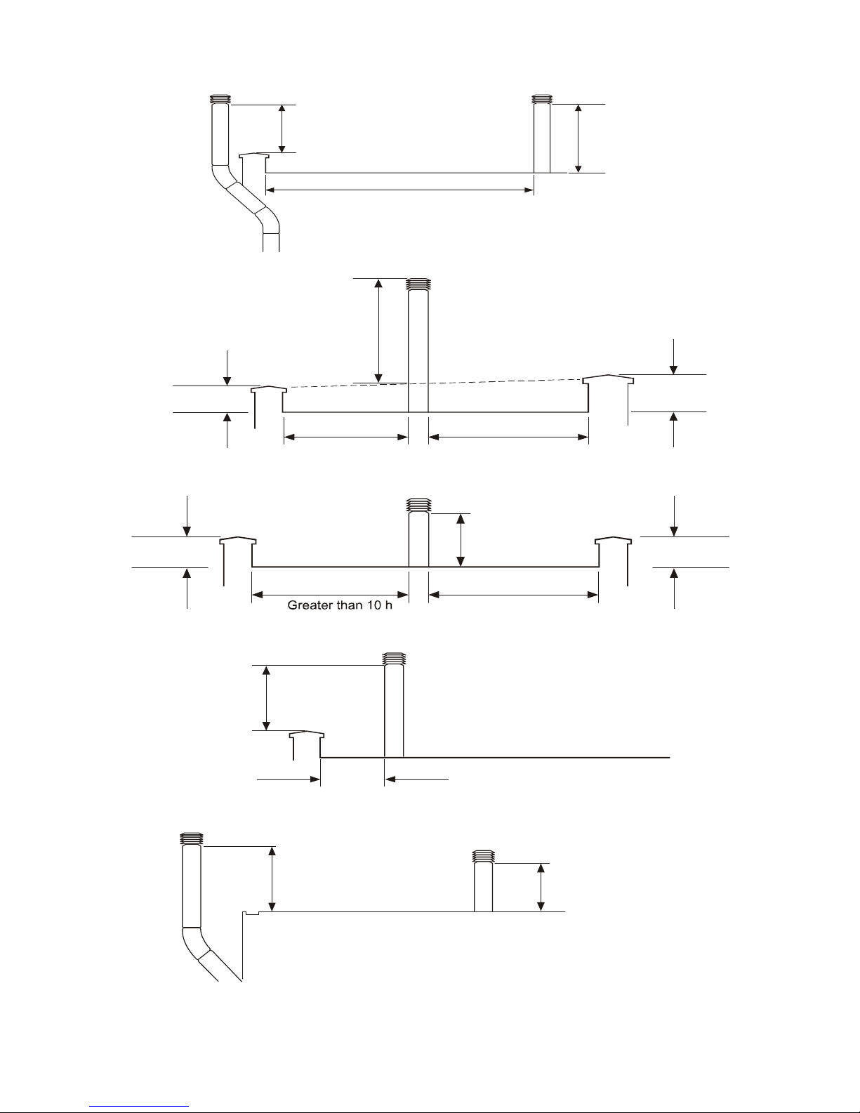
Not less than
600mm
Not less th a n
600mm
Greater than 1500mm
Parapet
Fig 2 Flat roof with parapet
Not less th a n
600mm
Less than 10 h
Greater than 1500mm
H
1
H
2
2
Less than 10 h
1
Fig 3 Flat roof envelope method
Structure
Not less than
250mm
2
Greater than 10 h
1
H
1
H
2
Structure
Fig 4 Flat roof where the flue height is more than 10 Heights (H) away from all structures
Structure
Not less th a n
600mm
Less than 1500mm
Fig 5 Flat roof with flue close to parapet
Not less than
600mm
Not less th a
n
250mm
Fig 6 Flat roof with no parapet
Page 14
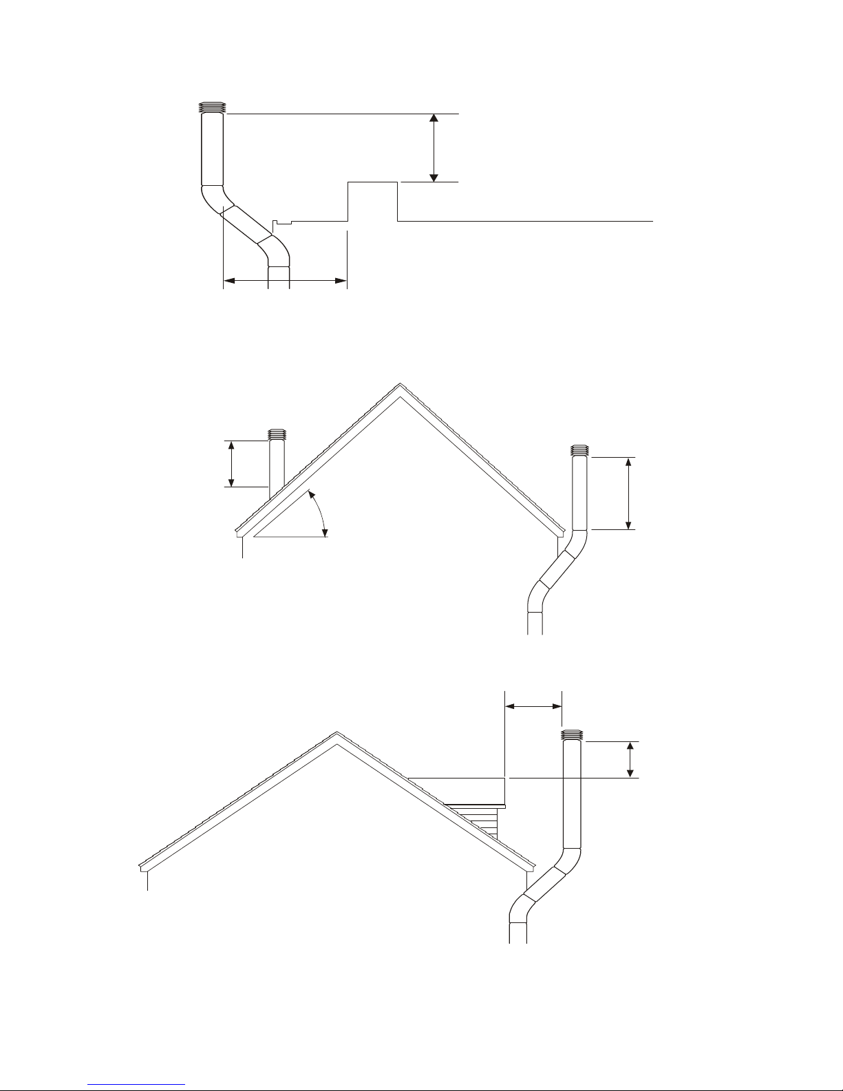
Not less than
600mm
Less than
1500mm
Structure
Fig 7 Flat roof with structure close to flue outlet
Not less th a n
600mm
Not grea t er tha n
45
°
Not less th a
n
600mm
Fig 8 Pitched roof not greater than 45°
Less than
1500mm
Dormer
window
Not less tha
n
600mm
Fig 9 Pitched roof chimney within 1.5m from dormer window measured horizontally
Page 15
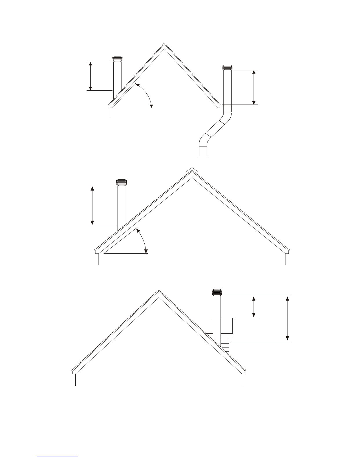
Greater
than 45
°
Not less tha
n
1000mm
Not less than
1000mm
Fig 10 Pitched roof exceeding 45°
Less
than 45
°
Not le s s than
600mm
Termination on ridge
Fig 11 Pitched roof internal route not exceeding 45° and ridge termination
Fig 12 Pitched roof chimney within 1.5m from dormer window measured horizontally
Not less than
600mm
Not less
than 1000mm
Dormer
window
Page 16

2.6 Electrical Installation
All electrical wiring and connections must be
in accordance with the relevant European,
National, and Local regulations as well as to
IEE Standards.
Warning
Ensure that the Electric and gas supplies are
turned off before any electrical work is
carried out on the heater. Also ensure that
wiring cannot make contact with any metal
surfaces liable to be subject to high
temperatures, and where insulation of the
wiring could be impaired as a result of such
contact.
All GUH models must be earthed.
Caution
The main electrical supply must not be
switched off or disconnected as a method for
stopping the heater, the exception to this is in
the event of an emergency, or when the
heater has been allowed to cool sufficiently
to prevent any damage from being sustained
to the heater or its controls (ie: during
servicing).
Claims for damage will not be considered if
they have resulted from incorrect wiring or
the incorrect use of the heater
Each heater requires a permanent 230V
50Hz 1ph electrical supply, which must be
wired through a fused isolator fitted with a
fuse of the correct rating (see section 7.1).
The correct supply connection points for the
live, neutral, and earth are clearly indicated
on the wiring diagram mounted inside the
wiring box cover.
Wiring diagrams are also detailed within this
manual, (section 6.0 )
The electrical supply isolator should be
mounted adjacent to the air heater in an
easily accessible position to allow for
servicing isolation, or emergency shut off.
2.7 Electrical panel
Warning
Ensure that the mains isolator is turned OFF
before undertaking any electrical on the
heater.
Access to the electrical panel is gained by
removing the right hand heater side panel,
(Lift the panel clear of the lower lip, pull panel
outwards and let it slide until it is retained by
the two lugs and the lower lip.
The panel can be fully removed by tilting one
of the top corners towards the heater thereby
disengaging the lugs).
The cover to the electrical panel can be
removed by undoing the two screws which
secure it to the panel.
Warning
Ensure that all connections are secure and
that there are no loose strands which could
bridge across the terminals.
A minimum conductor size of 1.0 mm
(diameter) is required.
Caution
One electrical
panel per heater
is required,
unless heaters
are specified for
multiple heater
control
applications. On
no account
should more
than one heater
be connected to
a single time
switch or
thermostat. The
Page 17

only exception
to this is when a
control panel
suitable for
multiple heater
applications is
supplied by the
manufacturer, in
which case the
wiring diagram
supplied with
the control
panel should be
read in
conjunction with
the existing
wiring diagram.
Any ancillary electrical items e.g. room
thermostats , time switches, remote panels
etc, must be wired into the heater electrical
circuit in accordance with the diagrams
provided
Note When external controls operate to
switch the heater OFF, power to the heater
should remain to allow the fan to continue to
operate to sufficiently cool the heater thereby
preventing damage to the heat exchanger.
2.8 Time switch
Caution
Time switches may only be fitted if they are
of an approved type, and must have
separate motor connections, the motor must
be connected to a suitable live and neutral
supplies, and with the switching contacts
then wired in series from the neutral side of
the room thermostat to terminal 7
Reference should be made to the wiring
diagrams contained with the time switch, and
within section 6.0 of this manual
2.9 Room thermostat
Any external room thermostat should be
fitted with the common terminal (if fitted with
changeover contacts) to terminal 5.
If the thermostat is fitted with a heat
anticipator this should be fitted to terminal 2.
The thermostat should be mounted at a
height of approximately 1.5mm from the floor
in an area where the ambient temperature is
representative of the area to be heated. The
siting of the room thermostat should be in a
draught free area. or in an area where
temperatures are free from the influences of
direct sunlight or heated discharged air.
2.10 Fan limit control
( Situated inside the right hand side panel)
Fan control (white button)
The fan control switch features normally
open 230V contacts, and is wired to control
the live supply to the fan motor . When the
circuit is made, the fan will switch on when
the heat anticipator has closed the fan switch
contacts. When the thermostat or time switch
shuts down the burner, the fan will continue
to run until the thermal switch has cooled
sufficiently to prevent the residual heat from
damaging the heater or its controls.
On startup the fan delay prevents air being
circulated until the desired temperature is
achieved
Limit control (red button)
An adjustable high temperature manual reset
limit control. If this control needs resetting the
cause should be determined and rectified
immediately.
On models with two fans a second limit
Page 18

control is situated inside the left side panel
and is wired in series. Operation of either
switch will shut down the heater
On the GUH
400 / 480 where
four fans are
fitted there are
separate
sensors again,
however as
these units are
modular they
will react much
the same as a
twin fan unit as
there are two
sensors per
module linked to
the relevant
control.
Caution
The power supply to the fan must not be
interrupted, the only time when power supply
can be disconnected or interrupted is during
servicing or in emergencies.
If there is a requirement for the heater to be
switched off over night then the gas valve
circuit should be opened via a time switch,
etc, as per the wiring instructions and
diagrams supplied within section 6.0 of this
manual.
2.11 Summer switch
A heat / ventilation switch may be fitted
remotely and connected between terminals
1. and 4.
This switch will allow the fan motor to run
continuously. Where the remote control box
is used, the burner is automatically inhibited
during the summer / ventilation setting.
2.12 Gas installation
Warning As there have been recorded
instances of the deposition of copper
sulphide dust within the valves and orifices of
gas appliances as a direct result of a reaction
between the hydrogen sulphide contained in
some natural gasses and copper pipe we
recommend that the heater(s) should not be
connected to any natural gas pipe
distribution system which utilizes copper
pipework, including final connections. Instead
steel pipework should be used throughout.
In the event that it is impractical to use steel
pipework or where installers are obliged or
insist on using elements of copper pipework
within the installation then we strongly
recommend that the gas supplier be
consulted as specific conditions and
requirements may be necessary.
Please read notice on PAGE 3 of this
manual
Only qualified and competent personnel are
allowed to undertake the installation,
commissioning, and servicing of Unit Heaters
The GUH range of heaters are all
manufactured and pre set for use with
Natural Gas, and all feature 3/4” BSP
connection points. Prior to installation the
supply characteristics (gas type and
pressure) must be checked to ensure that
they are in accordance with the data plate on
the heater.
The gas
Page 19

supplier should
check that the
meter and
service
connection to
the heater are
capable of
delivering the
required volume
of gas, thereby
ensuring that
the minimum
burner pressure
can be
achieved.
Consideration
should be given
to the pressure
drop on single
and multi heater
installations and
the effect they
may have on
other plant
sharing the
supply.
If it is necessary to fit a gas pressure
booster, the controls must include a low
pressure cutoff switch which must be fitted
on the supply / inlet side of the booster. It is
also a requirement that the gas supplier is
advised prior to the installation or fitting of
the booster.
Each heater supply must be fitted with a
separate isolating cock positioned adjacent
to and upstream of the union which must be
sited outside the heater the isolating cock
should be of the 90
0
turn type and should be
clearly marked OPEN / CLOSED
it should also be installed so as to fall to the
closed position
An approved gas jointing compound must be
used on all joints and unions and the system
purged and tested for soundness prior to
final connection
The connection to the heater can be made
by way of either an approved flexible
coupling or rigid connection . Threaded
connections must comply to ISO 288/1 or
ISO 7/1 further information concerning
accepted European practice is detailed in
June 1995 version of prEN1020 Annex 7.
The diameter of the pipework from the
isolating cock to the burner must not be less
than the diameter of the connection into the
multiblock.
Note Reference to The Institute of Gas
Engineers publications Utilisation Procedures
IGE/UP1 and IGE/UP2 together with
reference to BS6891 is strongly advised.
3.0 Commissioning
Page 20

Note
It is a requirement that only suitably qualified
and competent personnel are allowed to
undertake the commissioning of the heater.
It is also strongly recommended that prior to
commissioning the engineers familiarises
themselves with the heater. the specific
requirements of the installation /application,
and the information contained within the
manual.
Warning
All heaters are subject to a rigorous test
programme prior to despatch, whilst such a
programme does involve pre-commissioning
and the setting of the heater to operate
efficiently and within its designed operational
limits this does not mean that the function of
thorough on site commissioning is less
important
It is strongly recommended that the
equipment used for the sampling and
analysis of the flue gases is accurate to
within +/- 0.1% and maintained so that it is
regularly calibrated.
The following
pre-
commissioning
checks should
be undertaken,
having first
ensured that the
gas and
electrical
supplies are
turned off.
(a) Check that all panels and fasteners are
secure and in place.
(b) Check that the heater is mounted safely.
(c) Check that the flue is sealed, secured,
and adequately supported.
(d) Check that the fan is free to rotate, that
the fan is secured to its shaft, and that the
guards and fan assembly are all in place and
properly secured.
(e) Check that the heater is installed so that
it is not tilted and remains square.
(f) Check that the outlet louvres are set to
offer minimum resistance to air flow.
3.1 Electrical pre-tests
The electrical safety checks must include the
following
a) Test for earth continuity
b) Test for resistance to earth
c) Check live and neutral connections are
correct.
d) Check to ensure that when the external
controls operate to switch the heater off,
power remains to the fan
3.2 Gas supply pre-test
Ensure that the service pipework has been
installed purged and tested in accordance
with the relevant regulations, and that the
installation is served by an adjacent isolating
cock.
Connection from the supply to the heater
must also comply with the relevant
regulations (see section 8.0) and must have
been purged and soundness tested by an
authorised engineer.
3.3 Ignition sequence manual versions
Warning
Page 21

If during the following sequence of
operations the heater fails to operate
correctly the fault should be traced and
rectified before proceeding, if necessary
referring to section 5.0 fault diagnosis. If for
any reason the pilot light is extinguished no
attempt should be made to re light it
within three minutes
a) Switch off the main electrical supply to the
heater
b) Turn off gas supply to the heater
c) Remove side panel, and connect
manometers to the gas supply test point and
to the main burner test point
d) Ensure outlet louver’s are correctly set
e) Ensure fan rotation is not impaired or
obstructed
f) Set room thermostat to its lowest setting
g) If a time switch is fitted ensure it is set to
an on period
h) Switch on electrical supply
i) Turn on gas supply, and open burner
viewing port
j) Depress and hold in control start button
and test for soundness
k) Continue to depress start button whilst
operating igniter until pilot light is present
l) Hold in start button for at least one minute
to establish pilot - carefully release button
confirming presence of pilot
Warning
If the pilot fails to become established do not
attempt to re light for at least three minutes ,
if the pilot is established continue as follows.
m) Close burner viewing port
n) Turn thermostat to the highest setting, and
the main burner will light then re-open the
viewing port and check that the main burner
is providing a good flame i.e. even, stable,
and conical.
o) Check pressure readings on the
manometers, and continue to let the heater
fire for ten minutes
p) When the fan starts ensure that the
direction of rotation is correct , and that the
fan start is within two minutes of burner
ignition
Caution
If the fan fails to operate within approximately
two minutes and the heater goes to overheat
it will shut down through breaking the circuit
to the gas valve, the cause must be
ascertained and rectified before re-ignition.
Once the limit thermostat has tripped out it
must be manually reset to allow re-ignition to
take place.
q) After ten minutes check burner head
pressure is as specification - adjust as
necessary by removal of the gas pressure
adjustment cover, and using a screwdriver
turn the adjustment screw on the governor as
follows: Anti clockwise to reduce. Clockwise
to increase.
r) Check that the gas pressure remains
satisfactory for all appliances on the same
circuit
s) Undertake combustion tests checking CO
CO
2
and efficiency (see section 7.0) check
for spillage using a dry, water
cooled ,rhodium or chromium plate.
t) Check that the burners are extinguished
when the thermostat is set to its lowest
setting, and then remove the manometers.
u) Turn the thermostat to its highest setting
to re light the burner and replace the
adjustment screw cover
v) Check flame failure circuit by loosening
the connection between the thermocouple
and the overheat limit control on the main
gas valve, the ignition and main burners
should go out, retighten after testing
w) Turn the thermostat to its lowest setting
and shut off the gas supply at the gas control
Page 22

valve, allow the fan to continue to run until
the heater is cooled sufficiently for the fan to
shut down
x) Turn off the electrical supply
y) Set thermostat to desired room
temperature and replace the side cover
panel
z) Ensure that the user is familiar with the
heater and its controls and that the user is
satisfied with the commissioning and testing,
and that he is aware of the instructions within
the manual
It is strongly advised that the commissioning
engineer runs through the lighting, shutdown,
and general safe and efficient running of the
heater before hand over.
3.4 Ignition sequence automatic
versions
Automatic control is by way of a Satronic
controller (with automatic gas valve replacing
the manual standing pilot valve) used in
conjunction with a Satronic spark generator
(which replaces the piezo igniter as fitted to
manual units) , giving a maximum pilot
sequence of 15 seconds.
Flame supervision is via a flame sensor rod.
instead of the thermocouple as fitted to the
manual units.
The sequence is as follows: as per 3.3 a-i
The start signal will ignite the pilot, once the
flame proving has taken place the main gas
valve will supply the burner and burner
ignition will occur.
Continue as per 3.3 m-y
3.5 Hand over
Upon satisfactory completion of
commissioning and testing, the customer
should receive the completed guarantee and
commissioning card from the commissioning
engineer together with the user instructions
(section C). At the same time the user should
be made aware of the most efficient and
economical methods of operation.
The user must be familiar and satisfied with
the safety, ignition, shutdown, and general
operational procedures.
4.0 Servicing
Warning
It is a requirement that only qualified
personnel are allowed to carry out installation
commissioning or servicing.
In addition only spare parts recommended by
the manufacturer may be fitted, and the
installer should provide a list of
recommended spare parts that are available
through the manufacturer or his agent (see
section 9)
Before commencing any maintenance or
servicing work the heater must be shut down
and allowed to cool, and have the gas and
electric supplies to it turned off at the supply
cock and isolator respectively.
Always test for gas soundness after
completing any service work particularly
if this has necessitated the removal and /
or replacement of gas carrying
components
It is advisable that routine inspections are
carried out on a frequent basis, servicing
must also be carried out regularly, and in
accordance with the manufacturers
recommendations i.e. at a maximum interval
of one year. In certain applications the
frequency of servicing will have to be
increased, this to a large extent is governed
by the working environment, and both the
manufacturer and the installer will be able to
offer further advice.
A safe working platform giving good access
to the heater is required, It should be noted
that on suspended units the lower front panel
is removable so as to provide access to the
burner tray, injectors, and manifold, all of
which should serviced in the normal way as
detailed.
Clean all
accessible
surfaces
Page 23
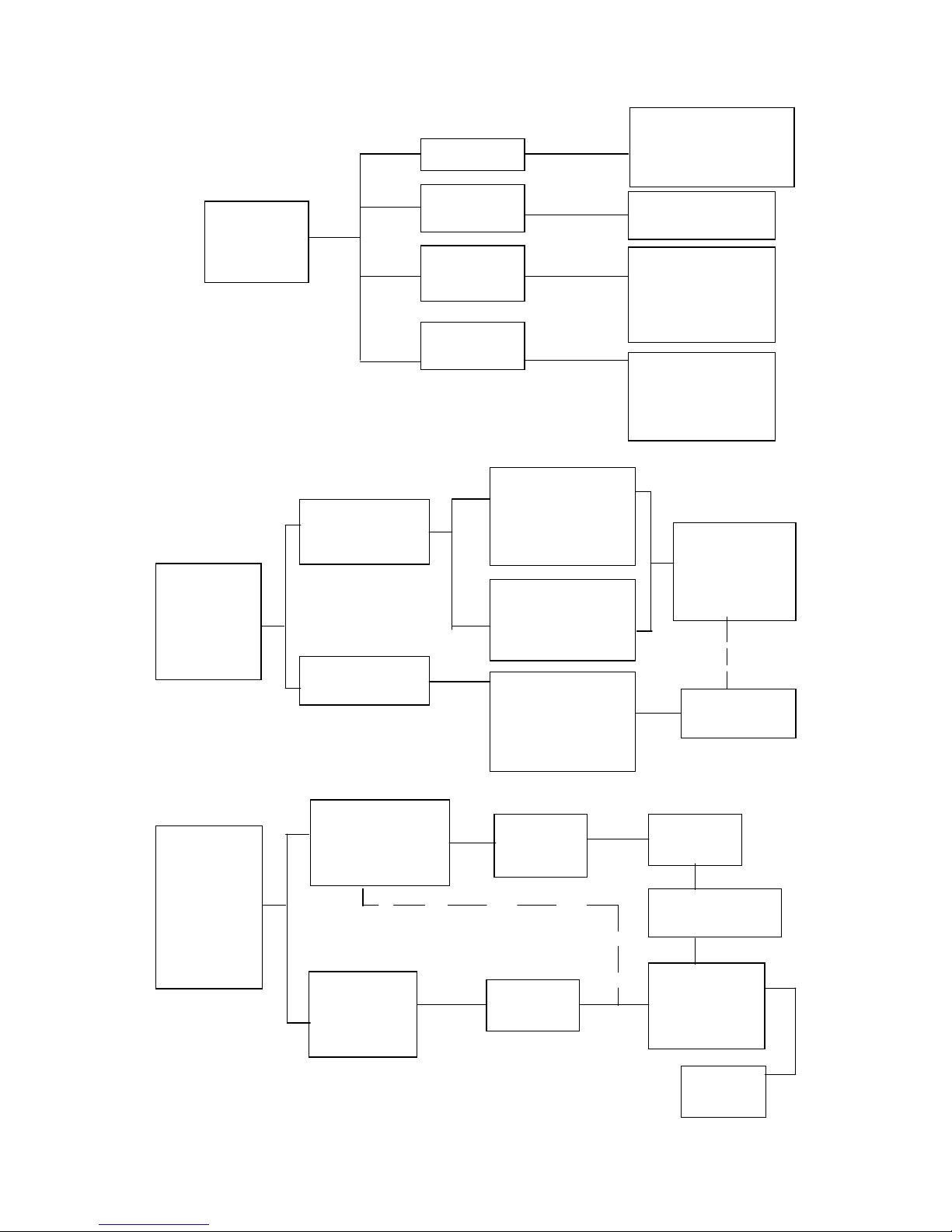
Pilo t
Burner
fails to
light
No Spark
Air in Gas
Supply
Pilot Feed
Restriction
Purge Gas Line
to Re mov e A ir
No Gas
Supply
Check Pilot
Adju s te r is F u lly
Open and that
the Pilot Tubes
are not blocked
Check Gas
Supply is Present
and that Gas
Taps are open
Che c k that th e Pilot
Flame Path is
supplying Heat to
the Thermocouple
Pilot Burner
Lights but
flame does
not become
established
Pilot Flame not
being sensed by
Thermocouple
Check that the Pilot
Flame Path is
supplying Heat to
the Thermocouple
Pilot Flame is too
small
Check that the
Thermocouple is
Connected to the
Gas Valve Co r rectly
Check that the Pilot
Flame Adjuster is
correctly set and
that the pilot feed is
Unrestricted
Reposition
Thermocouple
and / or Pilot
Flame Shroud
Replace Faulty
Thermocouple
Pilo t B urner
lights and
becomes
established
but th e Main
Burner fails
to light
Check that all
External Controls
are set to Demand
Heat
Check that
there is
Po w e r to th e
Heater
Check
Limit Stat
Reset
Check
Fuse
Check
Thermostat
Check Time
Switch
Check that the
Ga s Valve is
not Open
Circuit
Replace
Gas Valv
e
Page 24
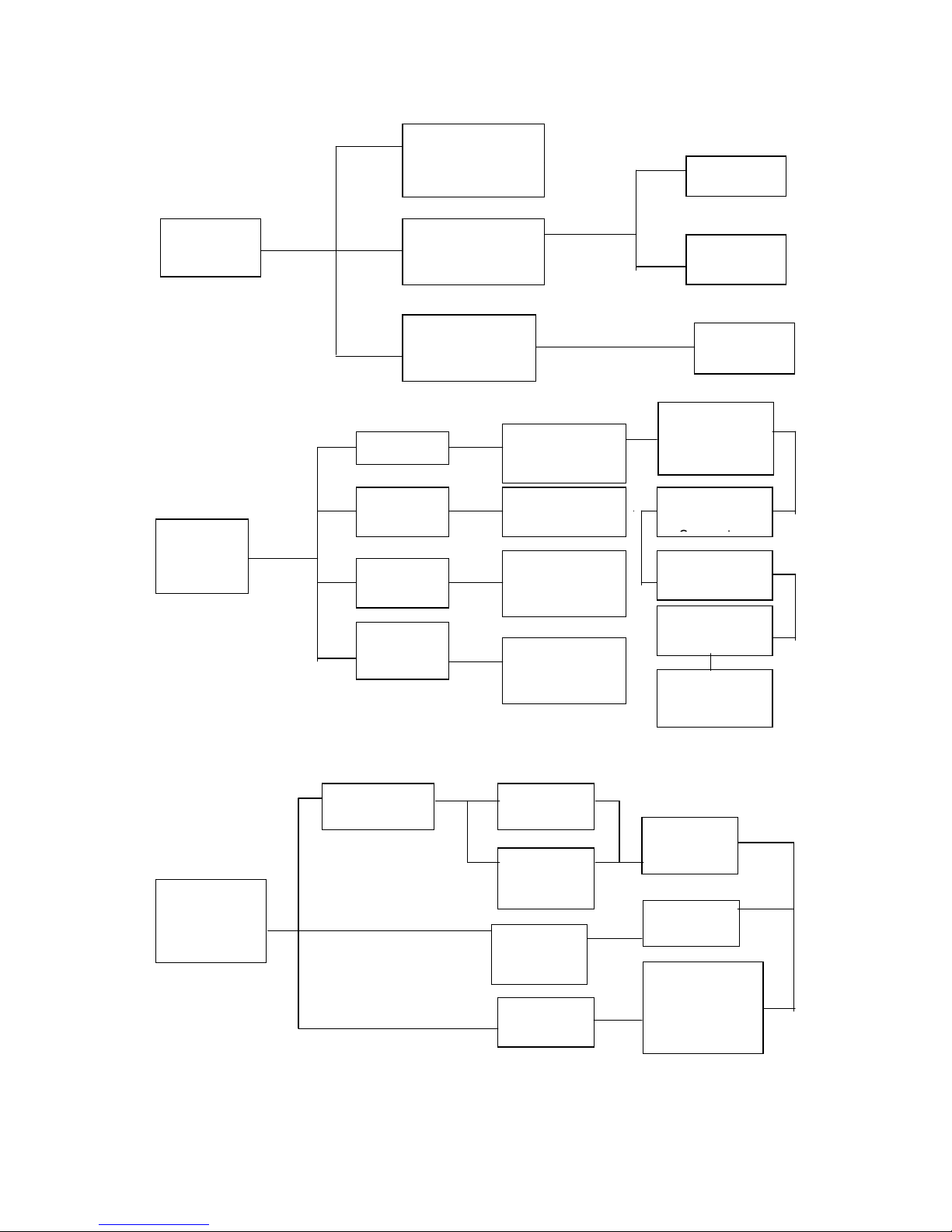
No
Operation
Check that Limit
Stat is not in Fail
Safe Position
Check Stat
Check
Timer
Check External
Controls are
Demanding Heat
Check there is
power to the
Heater
Check
Fuse
Pilot Will
Not Light
No Spark
Air in Gas
Supply
Pilot Line
Restricted
No Gas
Supply
Check Electrode
Gap is Correct
Purge System
to Rem o ve Air
Check that Pilot
Adjuster is set
Correc tly
Check Gas taps
are open and
Gas is Present
Check
Electrode is
not Cracked
Check HT
leads and
Check Spark
Generator
Check Control
Box
Replace Faulty
Unit
Pilot lights
but fails to
become
Established
Poor Signal
from Probe
Check
Flame Path
Check
Probe
Signal
Faulty
Control
Box
Pilot Flame
to Small
Replace
Faulty
Probe
Replace
Faulty Unit
Check Pilot
Flame Adjuster
is Fully O p e n
and Pilot Feed
is Unrestricted
Page 25

Pilot flame is
Established
but Main
Burner will
not Ignite
Faulty Wiring
from Control to
Valve
Replace
Faulty Control
Unit
Faulty Second
Stage Valve
Fan will
not Run
Fan
Control is
Open
Circuit
Check that
Fan will run
when Main
Gas is On
Replace
Faulty Fan
Control
Open Circuit to
Fan Motor
Check Wiring and
Connections
Fan runs
but stops
when Main
Burner is
alight
Faulty Motor
Fan Control is
Open Circuit
Low Ambient
Temperature
Check that
Fan will run
when Main
Gas is On
Check that
Fan cycles
On / Off.
Check Fan
Button,
Check Fan
Stat
Settings
Replace
Faulty Unit
Page 26
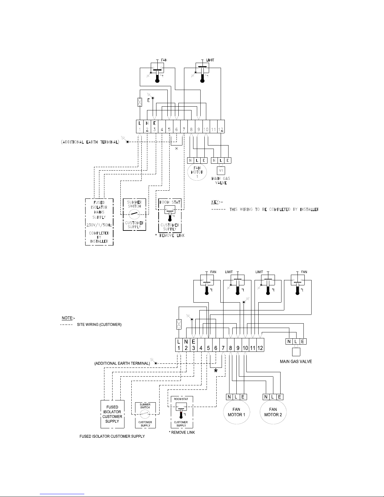
GUH 50 to 165 Piezo Ignition
6.0 Wiring Diagrams
GUH 205 – 325 Piezo Ignition
Page 27
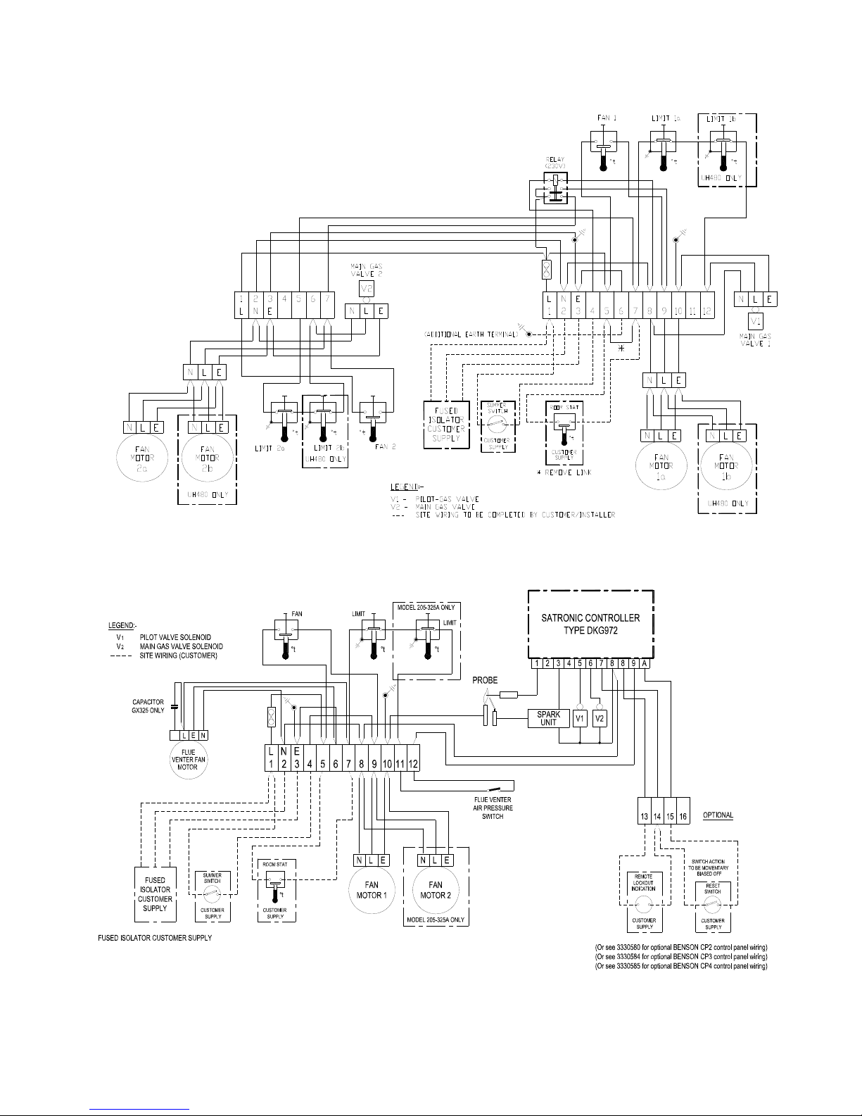
GUH 400-408 Piezo Ignition
GUH 50 – 325 Automatic Ignition
Page 28
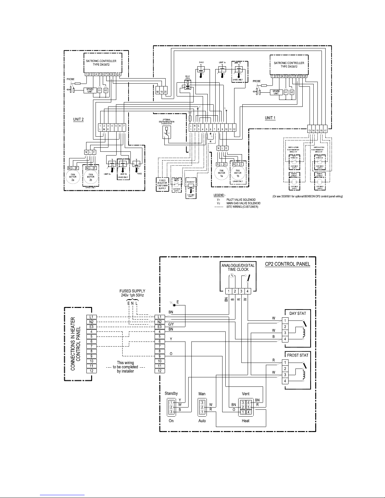
GUH 400 – 480 Automatic Ignition
T
CP 2 Control GUH 50 – 325 Piezo ignition
Page 29
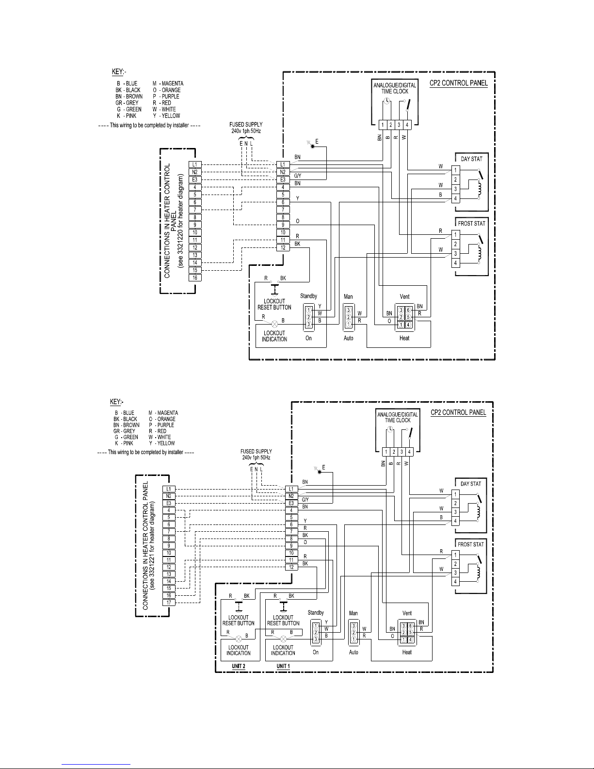
CP 2 Control GUH 50 – 325 Auto reset
CP 2 Control GUH 400 — 480 Auto reset
Page 30
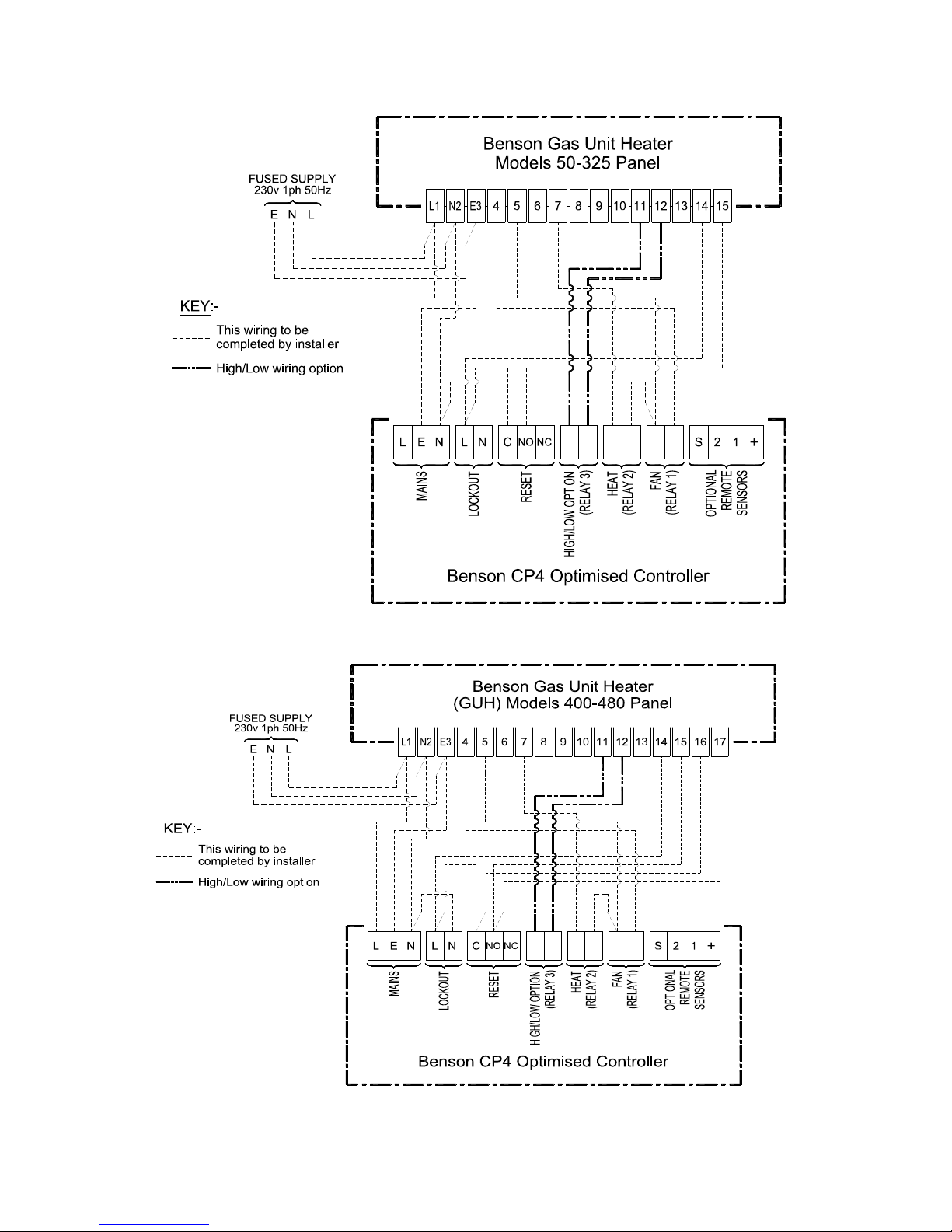
CP4 Control GUH 400 — 480
CP 4 Control GUH 50 — 325
Page 31
7.0 Technical Data
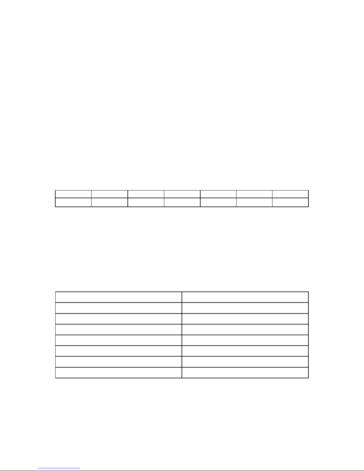
Formulae for calculating efficiency are detailed as follows
q1 is the heat of the dry products of combustion (% of heat released per unit volume of gas)
q2 is the heat of the water vapour contained in the products of combustion
(% of heat released per unit volume of gas)
C1 is the mean specific heat of
the dry products of combustion
(in MJ / (m3K) )
t1 is the average combustion air temperature (in oC)
t2 is the average temperature of the products (in
o
C)
H
i
is the net calorific valueof the gas at 1013 mbar and 15oC, dry (in MJ / m3)
H
s
is the gross calorific value of the gas at 1013 mbar and 15oC, dry (in MJ / m3)
Vf is the volume of dry products of combustion per unit volume of gas (in m
3
)
Ref Gas G110 G120 G20 G25 G30 G31
V CO2 0.26 0.32 1 0.86 4 3
The net efficiency , E (
net) (in % ) is given by : E (net) = 100 + (q1 = q2)
Where t
2
– t
1 Hs
- Hi
q1 = C1 x Vf ------------------ x 100 q2 = 0.077 ------------------- (t
2
– t1)
H
i
Hi
7.1 Technical Data Common Information
Gas supply Types
I
2E
+
I
2E ( R ) B
I
2H I2R
Destinations BE FR GB IE NL
Appliance Type B
11
PIN / report no 63AQ0533 / 160009
Electrical Supply 230V 50Hz 1ph
Fuse Rating 6 / 10 AMP
IP Rating IP44
Fan Limit Settings Fan On 60ºC Fan Off 30ºC Limit 100ºC
Page 32

MODEL NATURAL
GAS
GUH50 GUH75 GUH100 GUH125 GUH165 GUH205
HEAT
OUTPUT
kW
Btu
15.2
51,900
22.0
75,000
29.3
100,000
37.0
126,250
48.4
165,140
61.6
210,180
HEAT INPUT
(Gross)
kW
Btu
20.1
68,600
28.2
96,200
37.5
128,000
47.6
162,500
62.3
212,600
79.2
270,300
MINIMUM INLET
PRESSURE
mbar
Ins WG
17.5
7
17.5
7
17.5
7
17.5
7
17.5
7
17.5
7
BURNER
PRESSURE
mbar
Ins WG
13.2
5.3
13.0
5.2
6.5
2.6
7.1
2.8
7.4
3.0
7.4
3.0
NAT GAS
CONSUMPTION
ft3/hr
m
3
/hr
66.6
1.9
93.4
2.65
124.3
3.5
157.8
4.5
206.3
5.85
262.5
7.45
TEMPERATURE
RISE
ºC
ºF
28
82
34
93
33
91
32.6
90
32.5
90
33
91
AIR
FLOW
ft3/min
m
3
/sec
934
0.441
1114
0.526
1528
0.721
1860
0.878
2485
1.173
3060
1.444
AXIAL FAN
THROW
ft
mtrs
35
10.9
40
12.4
50
15.5
55
17.1
65
20.2
65
20.2
CENTRIFUGAL FAN
STATIC PRESSURE
Pa
Ins WG
75
0.3
100
0.4
100
0.4
125
0.5
163
0.65
125
0.5
SOUND LEVEL
Dba 57 63 63 69 72 72
GAS CONNECTION
BSP 3/4 3/4 3/4 3/4 3/4 3/4
MAIN INJECTOR
NATURAL GAS
mm
No Off
1.8
4
1.8
6
2.6
5
2.6
6
2.6
8
2.6
10
FLUE DIAMETER
mm 125 125 150 175 200 200
ELECTRICITY SUPPLY
230/1/50 230/1/50 230/1/50 230/1/50 230/1/50 230/1/50
ELECTRICAL POWER
(AMPERES)
Axial
Cent
0.4 0.8 0.8 1.5 1.7 2.0
FUSE RATING Axial
Amps 6 6 6 6 6 6
POWER ABSORPTION
Kw
Axial
Cent
0.1
0.4
0.15
0.63
0.15
0.63
0.36
0.85
0.36
1.05
0.3
1.26
AIR OUTLET
VENTILATION AREA
cm2
in
2
90
14
127
20
169
26
215
34
275
43
313
49
MOUNTING HEIGHT
(MTRS)
Min
Max
1.82
2.73
1.82
2.73
2.12
3.03
2.42
3.33
2.73
3.94
2.73
3.94
GROSS FLUE TEMP
ºC 170 180 170 180 170 180
WEIGHT
Kgs
Axial
Cent
70
81
88
101
107
120
123
136
155
175
188
216
7.2 Unit Heater Models Technical Data
Page 33

MODEL
NATURAL GAS
GUH250 GUH285 GUH325 GUH400 GUH480
HEAT
OUTPUT
kW
Btu
73.3
250,000
85.0
290,000
95.3
325,000
117.3
400,000
140.7
480,000
HEAT INPUT
(Gross)
kW
Btu
93.5
319,000
110.7
377,700
124.1
423,400
151.0
515,000
182.7
623,500
MINIMUM INLET
PRESSURE
mbar
Ins WG
17.5
7
17.5
7
17.5
7
17.5
7
17.5
7
BURNER
PRESSURE
mbar
WG
7.1
2.8
8.1
3.2
8.3
3.3
6.7
2.7
7.0
2.8
NAT GAS
CONSUMPTION
ft3/hr
m
3
/hr
300
8.5
341
9.65
396
11.2
494
14
600
17
TEMPERATURE
RISE
ºC
ºF
34.3
94
33
91
33
91
33
91
34.3
94
AIR
FLOW
ft3/min
m
3
/sec
3530
1.666
4284
2.022
4899
2.312
6120
2.888
7060
3.332
AXIAL FAN
THROW
ft
mtrs
70
21.7
80
24.8
90
28
65
20.2
70
21.7
CENTRIFUGAL FAN
STATIC PRESSURE
Pa
ins WG
125
0.5
163
0.65
163
0.65
150
0.6
163
0.65
SOUND LEVEL
Dba 72 70 70 72 73
GAS CONNECTION
BSP 3/4 3/4 3/4 2 x 3/4 2 x 3/4
MAIN INJECTOR
NATURAL GAS
mm
No Off
2.6
12
2.6
14
2.6
16
2.6
20
2.6
24
FLUE DIAMETER
mm 250 250 300 300 300
ELECTRICITY SUPPLY
230/1/50 230/1/50 230/1/50 230/1/50 230/1/50
ELECTRICAL POWER
(AMPERES)
Axial
Cent
1.9
8.4
3.1
8.4
3.3
9.6
4.0
9.6
3.9
8.4
FUSE RATING Axial
Amps 6 6 6 10 10
POWER ABSORPTION
Kw
Axial
Cent
0.3
1.26
0.72
1.26
0.72
2.1
1.1
2.1
0.6
2.5
AIR OUTLET
VENTILATION AREA
cm2
in
2
346
54
384
60
414
64
475
72
546
85
MOUNTING HEIGHT
(MTRS)
Min
Max
2.73
3.94
2.73
4.24
2.73
4.24
2.73
4.24
2.73
3.95
GROSS FLUE TEMP
ºC 170 170 170 140 150
WEIGHT
Kgs
Axial
Cent
218
246
266
313
303
351
386
442
436
492
7.2 Unit heater Technical Data Cont’d
Page 34

8.0 Reference Information
Doc/Ref Title/Subject
prEN 621 Non Domestic Gas Fired Forced Convection Air Heaters For Space Heating
BS EN 292 Parts 1 and 2; 1992 Safety of Machinery
BS EN 60204 Part 1; 1993 Safety of Machinery - Electrical
BS EN 60335 Part 1; 1988 Safety of Electrical Appliances
BS EN 55014 1993 Electromagnetic Compatibility
BS EN 50165 1995 Safety of Electrical Equipment
BS 5854 1980 Code of Practice - Flues/Flue Structures
BS 6891 1988 Installation of pipework < 28mm
BS 715 1993 Metal Flue Pipes and Fittings
BS 5440 Part 1 ; 1990 Specification/Installation of Flues
BS 5440 Part 2 ; 1989 Ventilation Requirements Gas Appliances
ISO 228/1 See also BS 2779 and BS 5380) Pipe Threads Seals and Couplings
UP / 1 Replaces IM / 5 and IM / 16 Installation of Gas Appliances
UP / 2 Replaces IM / 7 Installation of Gas Appliances
Page 35

Part Description GUH 50 GUH 75 GUH 100 GUH 125 GUH 165 GUH 205
Heat Exchanger Assy 33-10-598 33-10-599 33-10-600 33-10-601 33-10-602 33-10-603
Draught Diverter Assy 33-20-598 33-20-592 33-20-559 33-20-606 33-20-607 33-20-611
Gas Train Assembly 33-20-261 33-20-264 33-20-263 33-20-264 33-20-265 33-20-266
Pilot Installation Rhs 33-30-330 common common common common common
Control Box Assembly 33-20-326 common common common common common
Flue Kit Assembly N/A N/A N/A N/A N/A N/A
Control Box Lid 33-20-865 common common common common common
F & L Stat L4064 8” 28-60-023 common common common common common
Limit Thermostat (IMIT) N/A N/A N/A N/A N/A 28-40-059
Choke Plate Weld Assy 33-30-540 common 33-30-240 common common common
Manifold Assy Rhs 33-10-150 33-10-152 33-10-151 33-10-152 33-10-153 33-10-154
Copper Washer 91-00-052 common common common common common
Injector Nat Gas 33-30-538 common 33-30-302 common common common
Gasket 33-30-295 common common common common common
Gas Valve (Honeywell) 28-30-114 common common common common common
Pilot Burner c/w shear olive 28-90-148 common common common common common
Pilot Injector 28-90-153 common common common common common
Thermocouple 33-50-004 common common common common common
Ignition Electrode 28-90-156 common common common common common
Ignition Lead 28-02-172 common common common common common
Burner 33-00-123 common 33-00-124 common common common
Fuse Holder 28-07-050 common common common common common
Fuse 10 x 38 Axial 28-07-048 common common common common 28-07-048
Fuse 10 x 38 Centrifugal 28-07-048 common common common common 28-07-048
Fan/Motor Guard Assy Axial 28-09-041 28-09-039 28-09-039 28-09-040 28-09-036 28-09-042
Fan/Motor Guard Assy Cent 28-09-025 28-09-001 28-09-001 28-09-001 28-09-002 28-09-001
Fan Plenum Axial 33-10-626 33-10-634 33-10-540 33-10-554 33-10-528 33-10-567
Fan Plenum Cent 33-00-169 33-00-168 33-00-167 33-00-166 33-00-165 33-00-161
*Down Flow head 30 Deg 33-20-476 33-20-477 33-10-427 33-10-428 33-10-429 33-10-430
*Down Flow Head 90 Deg 33-20-502 33-20-503 33-20-504 33-20-505 33-20-506 33-20-507
*Vertical Louvre 33-20-943 common 33-20-873 common common common
*CP2 Control Panel 33-10-424 common common common common common
*Flue Ventor Assy 33-20-751 common 33-20-752 33-20-753 33-20-754 common
* Items marked are available as Optional Extras
9.0 Parts list
Page 36

Part Description GUH 250 GUH 285 GUH 325 GUH 400 GUH 480
Heat Exchanger Assy 33-10-664 33-10-604 33-10-605 33-10-603 33-10-664
Draught Diverter Assy 33-20-665 33-10-615 33-10-609 33-20-611 33-20-665
Gas Train Assembly Rhs 33-10-683 33-20-554 33-20-554 30-20-266 30-10-683
Gas Train Assembly Lhs N/A N/A N/A 33-10-712 33-10-717
Pilot Installation 33-30-330 33-30-553 33-30-553 33-30-330 33-30-330
Pilot Installation Lhs N/A N/A N/A 33-10-713 33-10-713
Control Box Assembly 33-20-326 33-20-326 33-20-326 33-10-716 33-10-715
Flue Kit Assembly N/A N/A N/A 33-21-155 33-21-155
Control Box Lid 33-20-865 common common 33-20-865 common
F & L Stat L4064 8” 28-60-023 common common 28-60-023 common
Limit Thermostat (IMIT) 28-40-059 common common common common
Choke Plate Weld Assy 33-30-240 common common 33-30-240 common
Manifold Assy Rhs 33-10-682 33-10-155 33-10-156 33-10-154 33-10-682
Manifold Assy Lhs N/A N/A N/A 33-10-715 33-10-718
Copper Washer 91-00-052 91-00-052 91-00-052 91-00-052 91-00-052
Injector Nat Gas 33-30-302 common 33-30-302 common 33-30-302
Gasket 33-30-295 common 33-30-295 common 33-30-295
Gas Valve (Honeywell) 28-30-114 28-30-103 28-30-103 28-30-114 28-30-114
Pilot Burner c/w shear olive 28-90-148 common 28-90-148 common 28-90-148
Pilot Injector 28-90-153 28-90-153 common 28-90-153 common
Thermocouple 33-50-004 35-50-004 35-50-004 35-50-004 35-50-004
Ignition Electrode 28-90-156 common 28-90-156 common 28-90-156
Ignition Lead 28-02-172 28-02-172 28-02-172 28-02-172 28-02-172
Burner 33-00-124 common 33-00-124 common 33-00-124
Fuse Holder 28-07-050 28-07-050 28-07-050 28-07-050 28-07-050
Fuse 10 x 38 Axial 28-07-048 28-07-048 28-07-048 28-07-049 28-07-049
Fuse 10 x 38 Centrifugal 28-07-048 common 28-07-051 28-07-051 28-07-051
Fan/Motor Guard Assy Axial 28-09-042 28-09-040 28-09-036 28-09-042 28-09-042
Fan/Motor Guard Assy Cent 28-09-001 28-09-001 28-09-002 28-09-002 28-09-001
Fan Plenum Axial 33-10-670 33-10-578 33-10-592 33-21-154 33-10-670
Fan Plenum Cent 33-10-672 33-00-164 33-00-163 33-10-706 33-10-672
*Down Flow head 30 Deg 33-10-678 33-10-431 33-10-432 33-10-430 33-10-678
*Down Flow Head 90 Deg 33-10-675 33-20-508 33-20-509 33-20-507 33-10-675
*Vertical Louvre 33-20-873 common 33-20-873 common 33-20-873
*CP2 Control Panel 33-10-424 common 33-10-424 common 33-10-424
*Flue Ventor Assy 33-20-754 33-20-755 TBA TBA TBA
* Items marked are available as Optional Extras
Parts list Cont’d
Page 37

SECTION B
WARRANTY
REGISTRATION
INFORMATION
Warranty terms and Conditions
1. In the first instance any warranty claim or
query concerning warranty, must be
communicated to the Service Department at
Benson Heating
2. Any part
manufactured
by Benson
Heating which
fails due to
defective
materials or
poor
workmanship
within twelve
months from the
despatch date
of the heater,
will be repaired
or replaced free
of charge,
inclusive of
parts and
labour.
3. Any part manufactured by Benson Heating
which fails due to defective materials or poor
workmanship within two years from the
despatch date of the heater will be replaced
free of charge on a parts only basis.
4. In addition to
2 and 3 above,
the heat
exchanger and
combustion
chamber carries
a ten year time
related warranty
based upon a
Page 38

S E C T I O N C
B A S I C U S E R
I N S T R U C T I O N S
10.0 Introduction
The following information is relevant to the
Gas fired GUH Cabinet Heater range
manufactured by Benson Heating. These
heaters are manufactured within a strictly
controlled quality system to ISO 9001.
All Benson Heating Cabinet Heaters are CE
marked, having been found to satisfy the
essential requirements of the following
European Directives.
Machinery Directive (89/392/EEC)
Low Voltage Directive (73/23/EEC &
93/68/EEC)
Electromagnetic Compatibility Directive
(89/336/EEC & 91/31/EEC)
Product Liability Directive (65/374/EEC)
Benson Heating support all new products
being supplied to their customers with a
comprehensive information pack, and it is the
responsibility of the owner, user, or hirer, of
such products supplied by Benson Heating
to ensure that operators are provided with
the operator manual, and that they are
suitably instructed regarding the purpose of
the manual and safety instructions. In
addition to this, operators must also be
suitably and adequately trained in the use of
the product.
Contained within the text of this manual, the
words
'Caution' and 'Warning' are used to
highlight certain points.
Caution is used when failure to follow or
implement the instruction(s) can lead to a
premature failure or damage being
occasioned to the heater or its component
parts.
Warning is used when failure to heed or
implement the instruction(s) can lead not
only to component damage, but can also
lead to a hazardous situation being created
where there is a risk of personal injury or
death
10.1 Commissioning and hand over
Warning
As part of the commissioning programme,
the commissioning engineer must go through
the following with the operator.
(i) Lighting, shutdown, and operational
information.
(ii) Safety features, data plate, and labelling.
(iii) The requirement for regular inspection especially if the heater is within a more
demanding environment - and the need for
regular servicing, carried out by competent
and qualified engineers.
Caution
After approximately 100 hours of running, the
tension on the fan belts must be checked to
ensure that it is correct, and that the belts
have not stretched.
It is strongly advised that this is undertaken
by the commissioning engineer, and not the
operator.
10.2 Servicing
Warning
Servicing must be carried out on a regular
basis, the maximum interval between
services being one year.
It is a requirement that only suitably qualified
and competent persons are allowed to
undertake the servicing.
Benson Heating advise that the planned
service schedule as detailed in section 4.1 of
the Installation, Commissioning and
Servicing Manual is adopted by the user.
Further details are available from either
Benson Heating or from the commissioning
engineer.
10.3 Start up procedure
Warning
If during the following sequence of
operations the heater fails to operate
correctly the fault should be traced and
rectified before proceeding, if necessary
referring to section 5.0 fault diagnosis.
Page 39

If for any reason the pilot light is
extinguished
no attempt should be made
to re light it within three minutes
a) Switch on electrical supply
b) Turn on gas supply, and open burner
viewing port
c) Depress and hold in control start button
whilst operating igniter until pilot light is
present
dl) Hold in start button for at least one minute
to establish pilot - carefully release button
confirming presence of pilot
Warning
If the pilot fails to become established do not
attempt to re light for at least three minutes ,
if the pilot is established continue as follows.
e) Close burner viewing port
f) Set the thermostat to the highest setting,
and the main burner will light then re-open
the viewing port and check that the main
burner is providing a good flame i.e. even,
stable, and conical.
Caution
If the fan fails to operate within approximately
two minutes and the heater goes to overheat
it will shut down through breaking the circuit
to the gas valve, the cause must be
ascertained and rectified before re-ignition.
Once the limit thermostat has tripped out it
must be manually reset to allow re-ignition to
take place.
g) Set controls as required
10.4 Ignition sequence automatic
versions
Automatic control is by way of a Satronic
controller (with automatic gas valve replacing
the manual standing pilot valve) used in
conjunction with a Satronic spark generator
(which replaces the piezo igniter as fitted to
manual units) , giving a maximum pilot
sequence of 15 seconds.
Flame supervision is via a flame sensor rod.
instead of the thermocouple as fitted to the
manual units.
The sequence is as follows: as per 10.3 a-i
The start signal will ignite the pilot, once the
flame proving has taken place the main gas
valve will supply the burner and burner
ignition will occur.
10.5 Stop procedure
(a) Set controller to off position.
(b) The fan motor will continue to run until
heat dissipation allows the fan and limit stat
to shut down the fan.
Caution
Do not use the main electrical isolator to turn
off the heater, to do so can cause damage to
the heat exchanger and combustion
chamber, and thereby invalidate the
warranty.
10.6 Shut down procedure
(
a) Follow steps 10.5 (a) and (b), when fan
stops turn main electrical isolator off, and
shut gas supply cock
10.7 Ventilation only
(
a) Set heat/ventilate switch to 'ventilate'.
10.8 Lockout situations
If either the burner or the fan and limit stat go
to lockout, the lockout must be cleared
manually before the ignition sequence can
be re-initiated.
Caution
Repeated or frequent lockouts must be
investigated and their cause determined by a
qualified and competent engineer.
Page 40

Benson Heating
Ludlow Road
Knighton
Powys
LD7 1LP
Telephone 01547 528534
Facsimile 01547 520399
Email [email protected]
Web www.bensonheating.com
Benson Heating is a Division of Benson Climate Systems Ltd
 Loading...