

Page 1
1403BSHH_AMEN
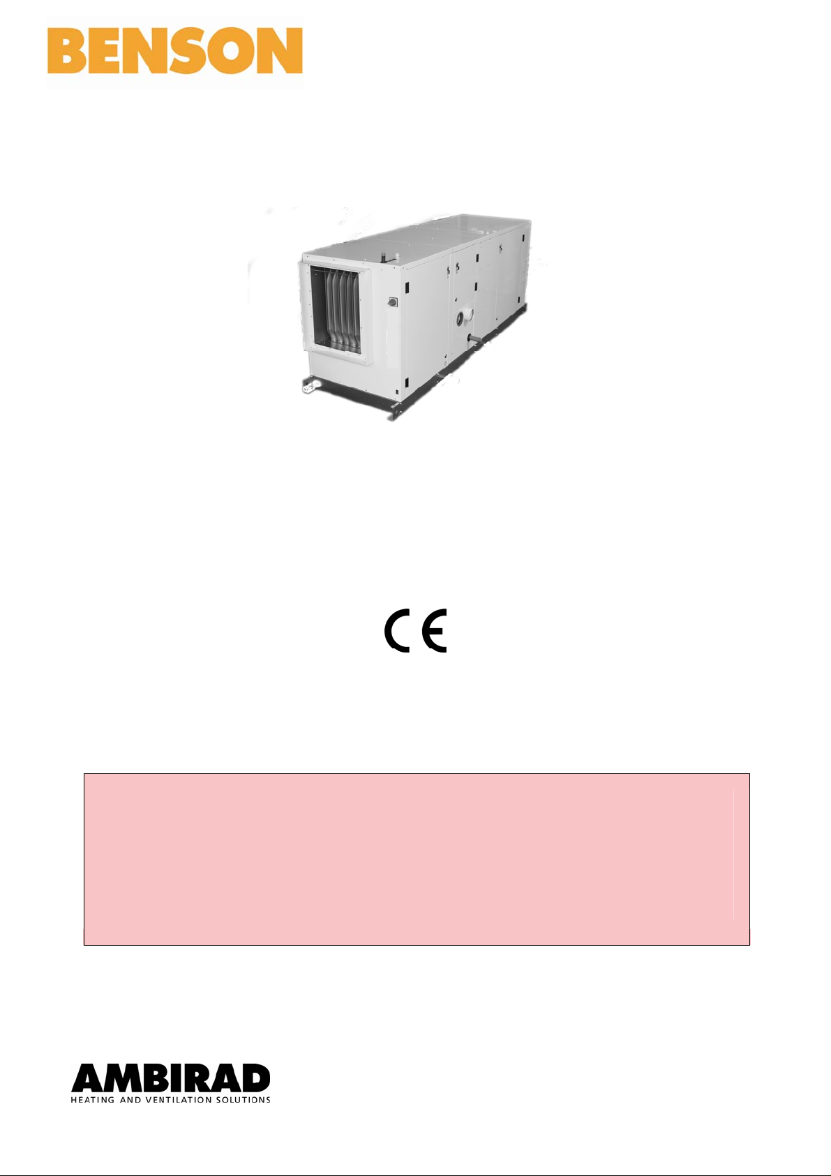
PRE-ENGINEERED VENTILATION AIR HANDLER
BSHH range (indoor system)
Centrifugal Blown, Forced Convection Appliances with
Automatic Ignition and Fanned Flues for use as Multiple
Type B & C Appliances
INSTALLATION
COMMISSIONING
SERVICING
These appliances meet the following EC Directives
DIR 2009/142/EC:GAD
DIR 2004/108/EC:EMC
DIR 2006/95/EC: LVD
DIR 2006/42/EC:MD
Please read this document carefully before commencing the installatio n and leave it with the user or
attached to the appliance or gas service meter after installation!
WARNING
Improper installation, adjustment, alteration, service or maintenance can cause property damage, injury
or death. All work must be carried out by appropriately qualified persons.
The manufacturer does not take any responsibility in the event of non-observance of the regulations
concerning the connection of the apparatus causing an evil operation possibly resulting in damage to the
apparatus and/or environment in which the unit is installed
Ambi-Rad Limited
Fens Pool Avenue, Brierley Hill, West Midlands DY5 1QA (United Kingdom)
Tel : 01384 489 700
Fax : 01384 489 707
www.ambirad.co.u
Subject to modifications
1403BSHH_AMEN,page 1/29
Page 2

Contents
1. General
1.1 General
1.2 Warranty
2. Moving and Uncrating
3. Technical Data
4. Configurations and Dimensions
5. Location and Installation
5.1 BSHH model
5.2 Duct connections
6. Combustion Air Supply and Flue System
6.1 General
6.2 Type B appliances
6.3 Type C appliances
7. Gas Connection
8. Electrical Connection
8.1 Electrical supply & connections
8.2 Thermostat controls
8.3 Fan motors
8.4 Wiring diagram
9. Commissioning, Lighting and Operation
9.1 Commissioning
9.2 Ignition system
GENERAL
1.1 General
BSHH units are design certified to the CE EN 1020
standard for use in industrial and commercial
installations only. All models and sizes are available for
use with either natural, propane or butane gas with
operating temperature between -15°C and 40°C. The
type of gas, input rate and the electrical supply
requirements are shown on the heating ratin g plate.
Before installation, check if the appliance as described
on the packaging label is in accordanc e with the correct
type and model as specified on the data plate and
complies with your customer order.
The installation manual is shipped with the heater. Verify
that the literature is correct for the heater being
installed. If the manual is incorrect for the heater,
contact the supplier before beginning installation. The
instructions in this manual apply only to the models
listed.
Installation should be done by a suitable qualified
installer in accordance with these instructions. The
installer is responsible for the safe installation of the
heater. BSHH heaters have a titanium stabili sed primary
heat exchanger with a Macro Ch annel
exchanger.
After unpacking the appliance leave it fastened to the
wooden blocks until just before siting t o prevent damage
to the base frame.
If optional equipment was ordered and supplied with this heater, please refer to additional instructions for
option(s).
1
TM
secondary heat
9.3 Operation
9.4 Burner gas pressure adjustment
10. Two Stage Burners Setting and Adjustment
11. Gas Conversion
12. Maintenance
12.1 Maintenance schedule
12.2 Heat exchanger maintenance
12.3 Burner maintenance
12.4 Burner orifice
12.5 Ignition system
12.6 Fan motor, fan
12.7 Venter motor & wheel
12.8 Operating gas valve
12.9 Combustion air pressure switch
12.10 Limit controls
12.11 Fan delay relay
12.12 Flue and combustion air piping
12.13 Air filters
13. Troubleshooting
14. Spare Parts List
15. User Instructions
Please read this document before commencing
installation.
These instructions are only valid for the country of use
as indicated on the appliance i.e. GB - IE. If these
symbols are not shown, it is necessary to obtain
appropriate technical instructions, which will provide
information concerning the necessary modification of th e
appliance for the conditions of use in the country
concerned. Such instructions may be obtained upon
request from your supplier.
Check if the local distributions conditions of electricity
supply, type of gas and pressure of the appliance are
compatible with the data plate. When installed in Great
Britain the total installation must comply with the
requirements and recommendations of British Standard
BS 6230 1991 “Installation of Gas Fired Forced
Convection Air Heaters for Commercial and Industrial
Space Heating".
The installation must also be in accordance with the
relevant requirements of "The Gas Safety (Installation
and use Regulations) and “A mendment regulations 199 0"
and the "Building and "Electrical Regul ations" (in GB the
IEE Regulations).
The requirements of the "Local Building Standards
office", the premises "Insurance" undertaking and the
"Fire Office" must also be observed.
1210SHH_AMEN,page 2/29
Page 3
Unauthorised modification of this ap pliance or departure
from use in the manner, for which it was intended by the
manufacturer or installed in a manner contrary to these
instructions, may constitute a hazard and jeopardize all
warranties.
Deviations should only be carried out after formal
consent has been obtained from t he manufacturer.
1.2 Warranty
Warranty is void if
a. Heaters are used in atmospheres containing
flammable vapours or atmospheres containing
chlorinated or halogenated hydrocarbons or any
contaminant (silicone, aluminium oxide, etc…)
that adheres to the spark ignition flame sensing
probe.
2
MOVING and UNCRATING
This unit was test operated and inspected at the factory
prior to packaging and was in proper operating c ondition.
Before leaving the factory, the unit is completely
assembled. If the heater has incurred damage in
shipment, document the damage with the transport
company and contact your supplier.
Read this booklet and become familiar with the
installation requirements of your unit. If you do not have
knowledge of local requirements, check with the gas
supplier and any other local agencies that might have
requirements concerning this installati on.
Before beginning, make preparations for necessary
supplies, tools and manpower.
:
Ensure the environment in which the air heater will be
installed will not create a hazard i.e. where excessive
(volatile) dust, flammable or corrosive subst ances and/or
vapours and combustible materials may be prese nt.
This appliance has been tested and set acc ording to the
data plate before leaving the f actory.
b. Wiring is not in accordance with the diagram
furnished with the heater.
c. Unit is installed without proper clearance to
combustible materials or without proper
ventilation and air for combustion.
d. Air throughput is not adjusted within the range
specified on the rating plate.
IMPORTANT
If the installation includes optional vertical louvers or
downturn nozzle etc., install these options before the
heater is suspended. Follow the instructions included in
the option package.
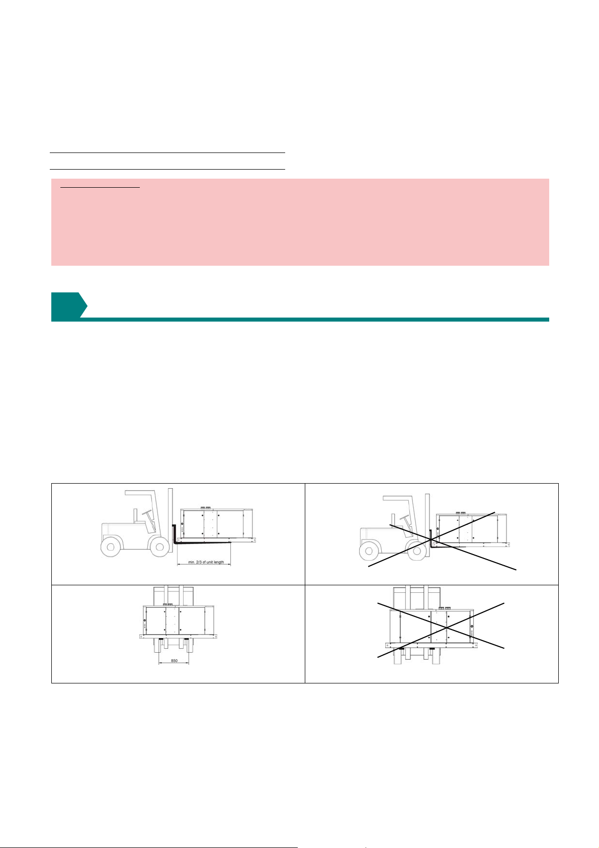
When transporting the appliance after it has been
unpacked (i.e. fork lifting, etc) note the restrictions and
recommendation indicated in figure 1.
The base frame contains internal supp ort member, which
acts as a lifting fulcrum point to prevent damage to the
underside of the appliance by lifting forks.
Figure 1: Appliance Handling Cri teria
Minimum fork length requirement : min. 2/3 of unit length
Minimum fork width for balance
WRONG
WRONG
1403BSHH_AMEN,page 3/29
Page 4
3
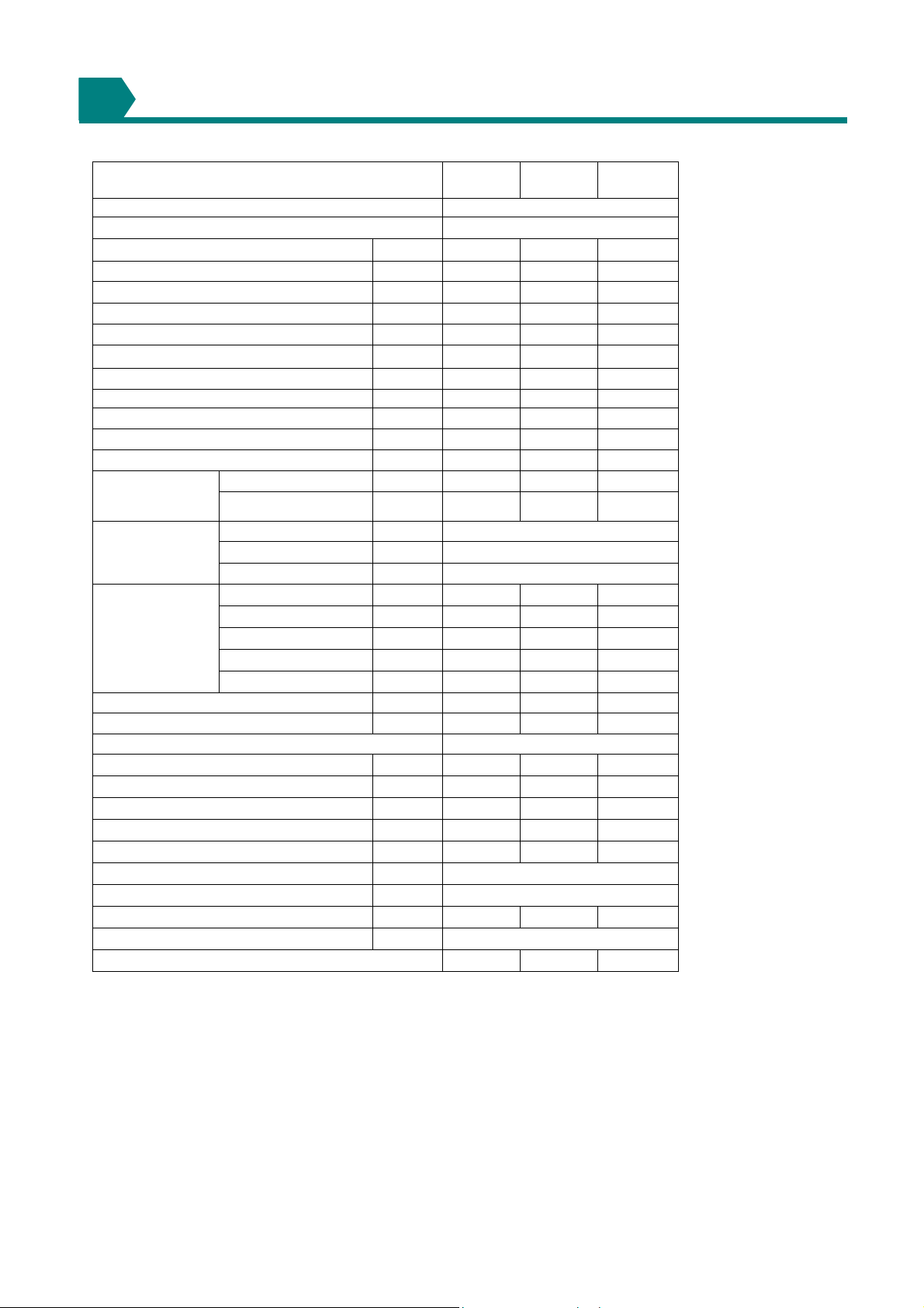
TECHNICAL DATA
Tabel 1 :
BSHH 055 083 102
Gas category 'Cat.' II2H3+
Combustion air & flue type B22p-B52-C12-C32-C42-C52-C62-C82
Heat input (Hs) kW 58.60 87.68 107.66
Heat input (Hi) kW 52.80 79.00 97.00
Heat output 100% (Hi) kW 53.86 80.19 98.94
Heat output 50% (Hi) kW 26.93 40.10 49.47
Thermal efficiency 100% (Hi) % 102.6 101.4 102.2
Burner pressure 100% (G20) 1) mbar 8.30 10.40 8.80
Burner pressure 50% (G20) 1) mbar 2.08 2.60 2.20
Burner pressure 100% (G31) mbar 15.70 34.36 23.50
Burner pressure 50% (G31) mbar 3.92 8.59 5.87
Burner pressure 100% (G30) mbar 12.31 26.93 18.42
Burner pressure 50% (G30) mbar 3.07 6.73 4.60
Burner injectors:
Quantity 1
Gas supply
pressure
Gas consumption (3)
NOX emission 100% G20 mg/kWh
NOX emission 50% G20 mg/kWh
Gas service connection
Flue & Combustion air connection collars)
Minimum airflow 4) at 15°C m3/h
Temperature rise at minimum airflow
Maximum airflow 4) at 15°C m3/h
Temperature rise at maximum airflow
Electrical connections and Fan motor rating 0.75-5.5kW / 400V 3N~50Hz
Total electric rating kW (Fan motor rating / 0,85) + 0,15
Appliance weight net kg 280 445 457
Protection grade IP 20
Quantity primary heat exchanger elements 6 9 12
Nat. Gas (G20)
Propane/Butane
(G31/G30)
Nat. Gas (G20) mbar 20(GB) / 20(IE) 2)
Propane (G31) mbar 37 2)
Butane (G30) mbar 28-30
Nat. Gas (G20) m3/h 5.59 8.36 10.26
Propane (G31) m3/h 2.16 3.23 3.97
Butane (G30) m3/h 1.64 2.45 3.01
Propane (G31) kg/h 4.12 6.16 7.57
Butane (G30) kg/h 4.17 6.23 7.65
mm
mm
mm
K
K
6.80 7.60 8.90
4.50 4.50 5.60
2)
127.32 128.48 129.79
78.48 97.81 112.22
¾" BSP
100 130 130
5500 8500 10000
28.6 27.6 28.9
8500 11800 14000
18.5 20.0 20.6
1) All burner pressures measured with all casing panels fitted and service door open. Pressure regulator sealed and not adjustable without
high/low fire control.
2) G20: Pmin. 17mbar / Pmax. 25mbar---G30: Pmin. 20mbar / Pmax. 35mbar--G31: Pmin. 25mbar / P max. 45mbar.
3) Natural gas (G20): Hi 34,02 MJ/m³--Propane (G31): Hi 88,00 MJ/m³--Butane (G30): Hi 116,09 MJ/m³ @15 °C and 1013mbar.
4) Isothermic @15°C - maximum temperature rise 40K (Please check the separate leaflet 'ventilator curves for the desired airflow and/or
static pressure with ad ju sted fan motor ratings).
1210SHH_AMEN,page 4/29
Page 5
4
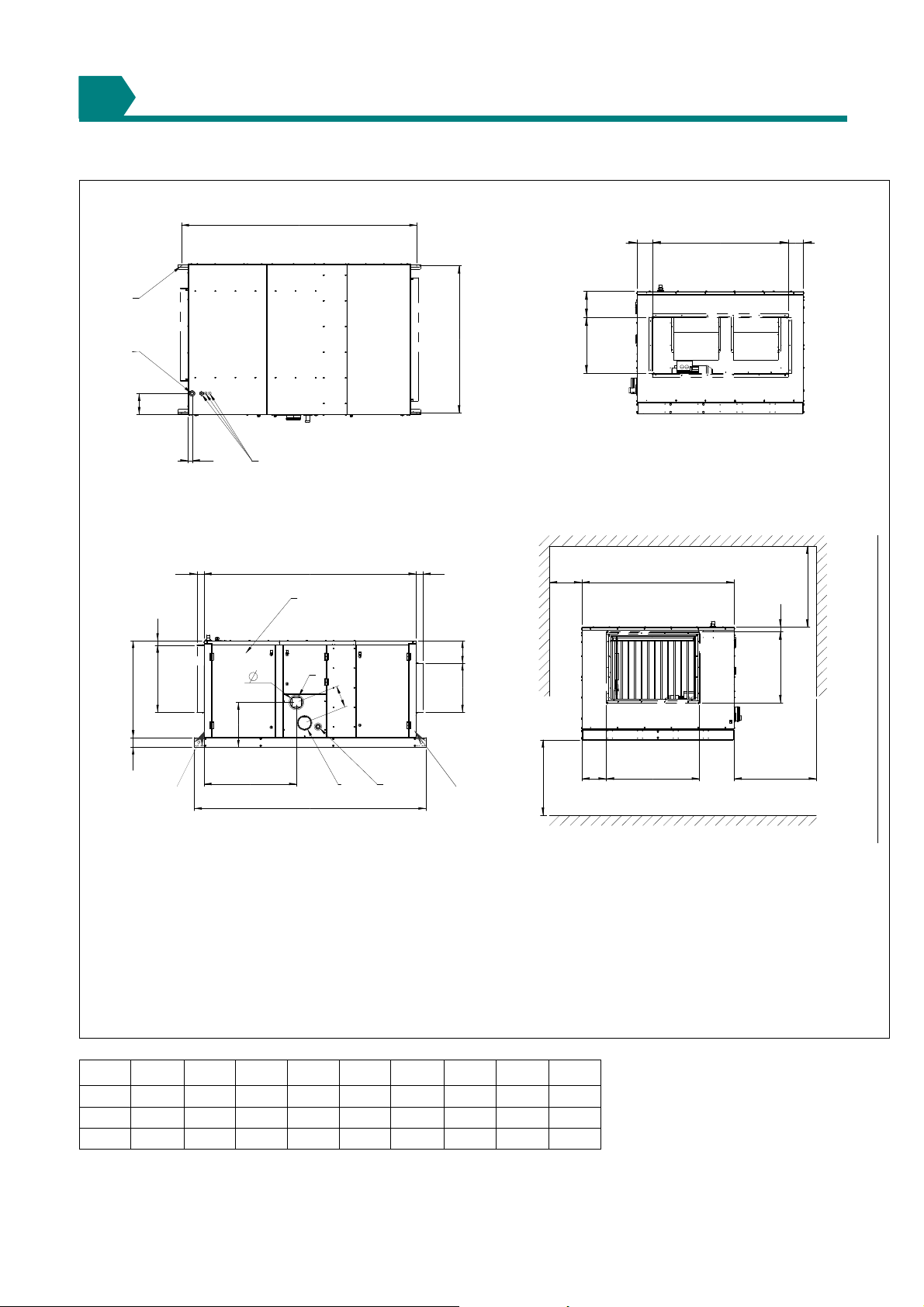
CONFIGURATIONS – DIMENSIONS - CLEARANCES
Figure 2
Top view Rear view
2289
E F E
6
230500
4
K
40
Side view
75 75
47
684
988
100
6
3
5
D
458
940
2359
2159
2
J
Front view
min
150
230500
G
1
7
6
min 2500
B
A
47
684
C
min 730
min 200
air inlet
flue outlet
electrical connections
gas connection ¾”
service panel
suspension points
condense drain dia 32 mm (female)
Type A B C
055 840 29 581 100 120 600 140 806 157
083 1468 236 899 130 134 1200 225 1434 301
102 1468 236 899 130 134 1200 225 1434 208
∅D
E F G J K
1403BSHH_AMEN,page 5/29
Page 6
5
LOCATION & INSTALLATION
5.1 General
5.1.1 Location heater
For best results, the heater should be placed with
certain rules in mind. Always ensure that minimum
clearances are maintained (cfr. figure 2). When
possible, heaters should be arranged to blow toward or
along exposed wall surfaces.
Suspended heaters are most effective when located as
close to the working zone as possible, but care should
be exercised to avoid directing the discharged air
directly on to room occupants.
Partitions, columns, counters or other obstructions
should be taken into consideration when locating the
unit heater so that a minimum quantity of airflow will be
deflected by such obstacles.
When units are located in the centre of the space to be
heated, the air should be discharged toward the
exposed walls. In large areas, units s hould be located to
discharge air along exposed walls with extra units
provided to discharge air in toward the centre of the
area. For optimum results heaters are best used in
conjunction with recirculating air fans suspended at high
level.
At those points where infiltration of cold air is excessive,
such as at entrance doors and shipping doors, it is
desirable to locate the unit so that it will discharge
directly toward the source of cold air, typically from a
distance of 4.5 to 6.0 meters or ins tall a down flow unit
over the door opening.
Do not locate the heater where it
may be exposed to water or where
the ambient temperature exceeds
The presence of chlorine vapours in the combustion air
of gas-fired heating equipment presents a potential
corrosion hazard.
Care should be taken to separate these vapours from
the combustion process. This may be done by wise
location of the unit flue and combustion air terminals
with regard to exhausters or prevailing wind directions.
Chlorine is heavier than air. Keep this fact in mind when
determining installation location of th e heater in relation
to building exhaust systems.
Where chlorine vapours are prevalent heaters with
special grade 316 AISI stainless steel heat exchangers
are recommended.
5.1.2 Installation heater
Figure 2 shows the clearances necessary to ens ure that
safety from combustibles and for servicing are
maintained. In the event that the appliance is required
to be installed on the floor then a non-combustible bas e
must be provided.
Installation on a base is required when the air handler is
composed of more than a heating and ventil ation section
– suspension becomes here forbidden.
In case the installation is done by means of supporting
points, make sure that the distance b etween supporting
points does not exceed 1.5m. In general it is
recommended to support the base where it is screwed
down with supporting points.
40°C.
Ensure that the structural elements, which will be used
to suspend or support the appliance, are adequate to
carry the weight of the appliance and its ancillary
components i.e. the flue system.
The location where the air heater is to be installed must
provide sufficient space around the heater for servicing
and clearances for safety. Beware to allow space for
the passage of vehicles i.e. lift trucks, etc …
Ensure that the air heater is i nstalled in a level plain.
The heater must be fastened securely to any base
mount framework.
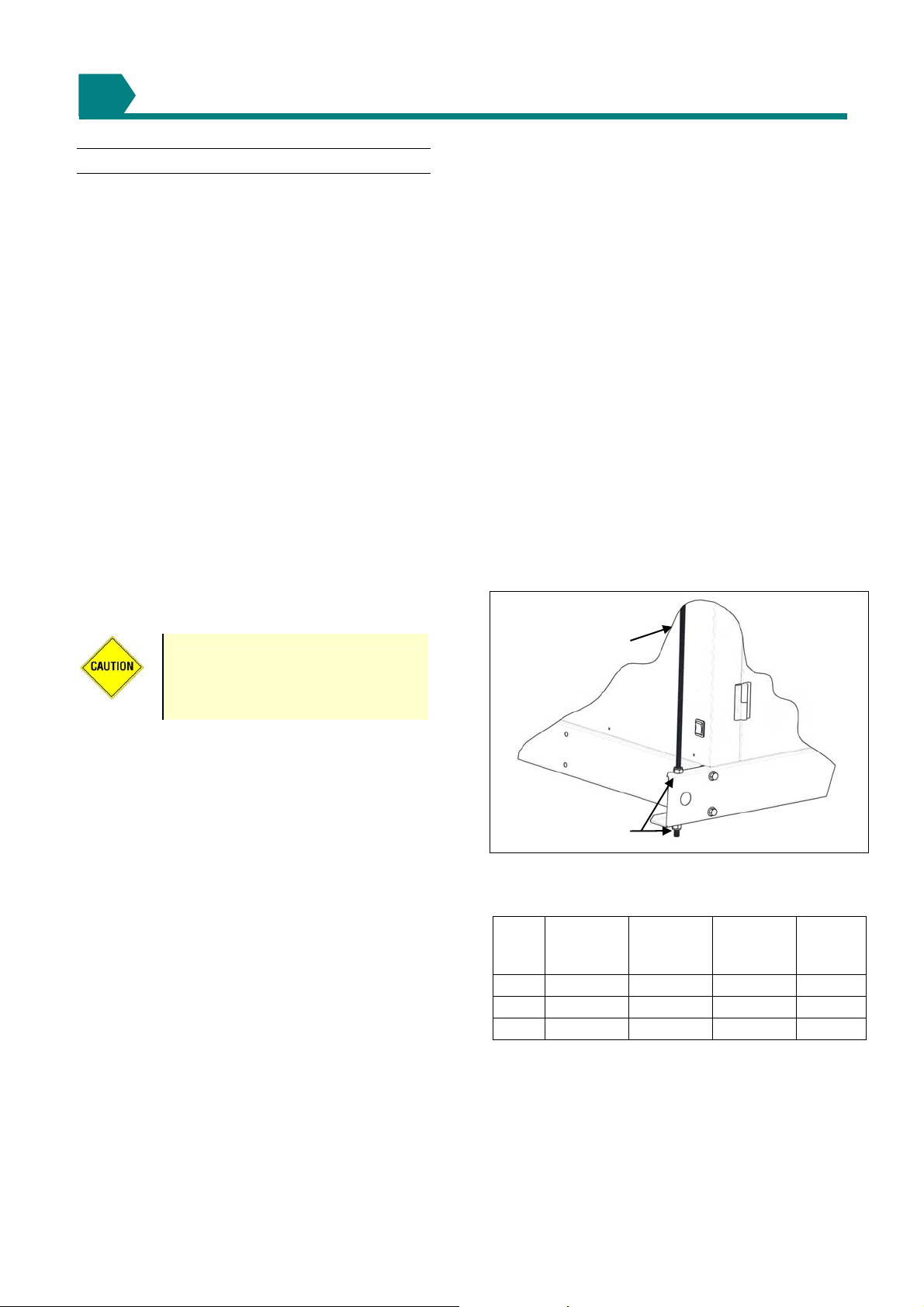
Four-point suspension is possible from the Ø 11.0 mm
holes provided in the base frame. Using drop rods etc.
Ensure that suspension fixings are lock nut secured to
secure against loosening.
When suspended, the air hea ter should be rigid so as to
avoid placing a stain on the flue s ystem and connected
services.
Figure 3 : Detail fixation (only if unit & framework is
a one-part construction )
Hanger rod M10
2x nut &
2x washer M10
Table 2: Clearances (mm) (we also refe r to figure 2)
BSHH Minimum
distance wall
not controls
side
055 150 730 2500 200
083 150 730 2500 200
102 150 730 2500 200
Minimum
distance wall
controls side
Minimum
distance
floor-bottom
Minimum.
distance
ceilingtop
1210SHH_AMEN,page 6/29
Page 7
5.2 Duct connections
The air heaters are designed to be used in conjunction with
intake and or discharge ducting. A positive seal should be
made between any ducting and the air heater. A flexible
connection is desirable to eliminate transmission of noise
and to take account of thermal expansion. Figure 5
illustrates a method of connection between the appliance
and the duct using a proprietary patented connection
system.
Consideration should be given to the application of duct
fittings directly connected to the appliance. Air inlet and
outlet elbows, transitions etc. should be des igned to ensure
an unrestricted and turbulent free ai r flow. This requirement
is to ensure that an even air temperature is maintained
when leaving the appliance thus eliminating heat exchanger
"hot-spots" and nuisance shut-down of the burner due to
over heating.
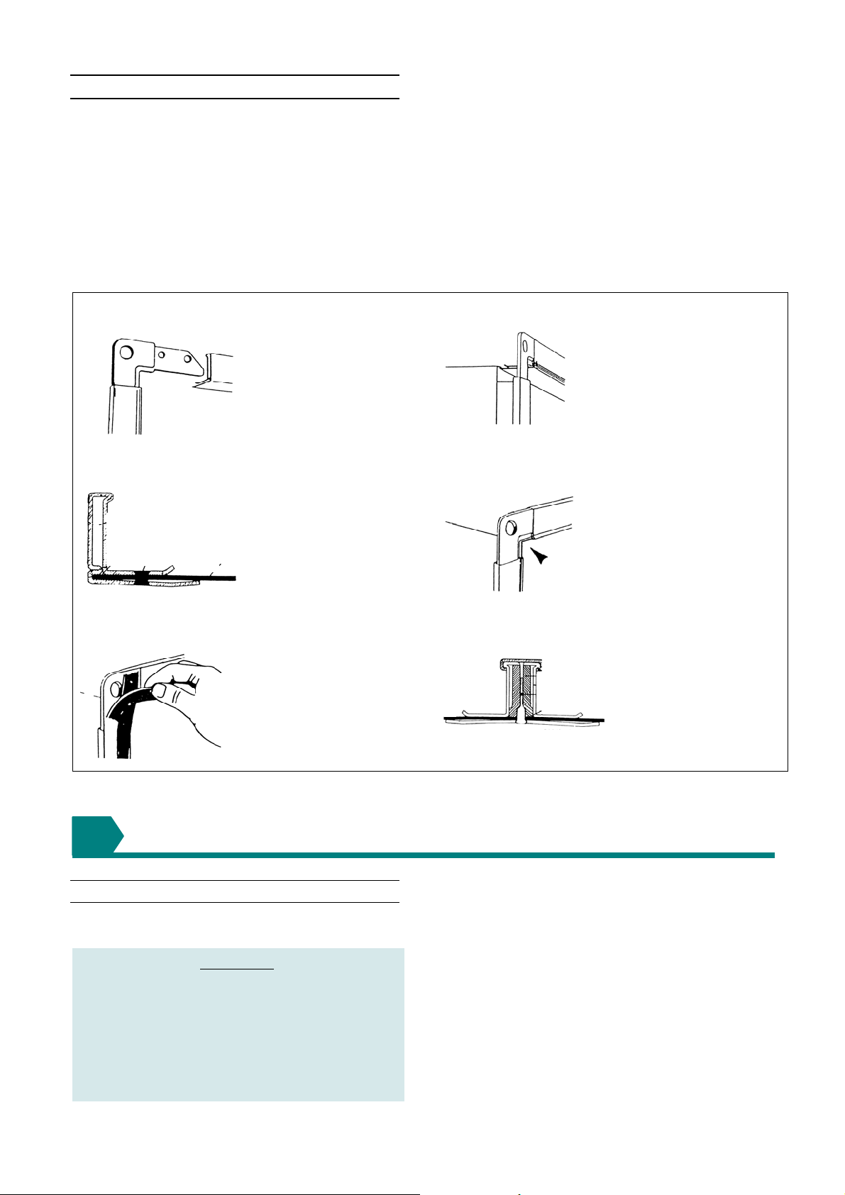
Figure 4 : Recommended procedure and method for connection of ducting and transitions to the air heaters using
a typical proprietary flange sys tem.
1 Corner jointing framework
2 Cleats between sections to be joi ned
Cut and assemble flange
into frame to suit opening
3 Fastening through all member s
Ensuring flange is mated
correctly before fastening.
5 Applying gasket seals to prevent air leakage
Check dimensions and
position on duct spigot.
4 Checking alignment a nd joint worthine ss
Checking location after
positioning.
6 Sectional view of completed joint
6
COMBUSTION AIR SUPPLY & FLUE SYSTEM
6.1 General
6.1.1 Flue requirements
IMPORTANT
The flue must be installed in accordance with
national and local re gulations. Failure to pr ovide
proper flueing could result in death, serious
injury and/or property damage. The air heater
must be installed with a flue to the outside of the
building. Safe operation of any power vented gas
apparatus requires a properly operating flue
system, correct provision for combustion air and
regular maintenance and inspection.
Model BSHH heaters may be installed as Type-B and
Type-C installations.
Flue must be in accordance with BS6230 or BS5440.
Local requirements may apply in addition to national
requirements. These unit heaters are designed to
operate safely and efficiently with either a horizontal or
vertical flue system when installed with the specific
requirements and instructions.
If this heater is replacing an existing heater, be sure that
the flue is sized properly for the heater being installed
and that the existing flue is in good co ndition.
1403BSHH_AMEN,page 7/29
Page 8
A properly sized flue system is required for safe
operation of the heater. An improperly sized flue system
can cause unsafe conditions and /or create condens ation.
The air heaters may be installed as a balanced flue (type
C) heater requiring both a combustion air inlet duc t and a
flue pipe or as a power vented heater (type B) (the
combustion air is taken from the space where heater is
installed), which requires only a flue pipe exhausting to
outdoors.
All products of combustion must be flued to outdoor
atmosphere. Each heater installed as a type B appliance
must be fitted with an individual flue pipe and the
combustion air inlet opening must be provided with a
protection grill.
Each heater installed as a type C appliance must be
fitted with an individual combustion air/flue pipe system.
Type C2 appliance, with single duct system for supply of
combustion air and evacuation of flue gasses, are not
allowed.
6.1.2 Diameter & maximum flue pipe lengths
Flue pipe diameters and maximum pipe l engths in table 3
apply to both horizontal an d vertical systems.
Add all straight sections and equivalent lengths for
elbow. The total combined length must not exceed the
maximum flue length.
6.1.3 Venter outlet attachment requirements
Depending on the size of flue pipe as determined in table
3, attach either the flue pipe directly to the collar or a
taper-type connector.
Table 3 : Maximum flue system pipe lengths
BSHH 055 083 102
flue pipe 100 1 30 130
Heater socket & pipe dia
Max straight length hor.
flue outlet connection
Max straight length vert.
flue outlet connection
Equivalent length of 45°
elbow
Equivalent length of 90°
elbow
- Use only one type of flue pipe dia
- recommended minimum flue length = 1m
mm
inlet pipe 100 130 130
flue pipe 9 9 9
m
inlet pipe 9 9 9
flue pipe 9 9 9
m
inlet pipe 9 9 9
flue pipe 0,75 0,75 0 ,75
m
inlet pipe 0,75 0,75 0,75
flue pipe 1,5 1,5 1,5
m
inlet pipe 1,5 1,5 1,5
IMPORTANT : CONDENSE DRAIN
A condense drain with trap must be fitted to the unit to
properly drain all condensation. The flue must be
installed in accordance with national and local
regulations. Failure to provide proper fl ueing could result
in death, serious injury and/or propert y damage. The air
heater must be installed with a flue to t he outside of the
building. Safe operation of any power vented gas
apparatus requires a properly operating flue system,
correct provision for combustion air and regular
maintenance and inspection. The combustion products
are loaded with moisture, some of which will condense
out within the flue. No condensate leakage is permit ted.
BSHH indoor horizontal flue runs must rise by 1° (17mm
per meter) from the appliance to ensure that the
condense returns to the flue d rain.
Gasket sealed single wall seamless heavy gauge
aluminium pipes are required for use with condensing
gas appliances. All joints must be sealed to prevent
leakage of flue gases or condensation into the building.
For testing, the flue pipe should include a sealable test
point. Ideally the test point should be at least 450mm
away from the air heater flue connection socket.
However if a concentric flue is attached directly to the
connection sockets then the combusti on should be tested
through the flue outlet collar via a drilled test point which
must be securely plugged on completion . Follow the flue
pipe manufacturer’s installation instructions for making
joints, including connections to the air heater, for
passing through a building element and for support
requirements.
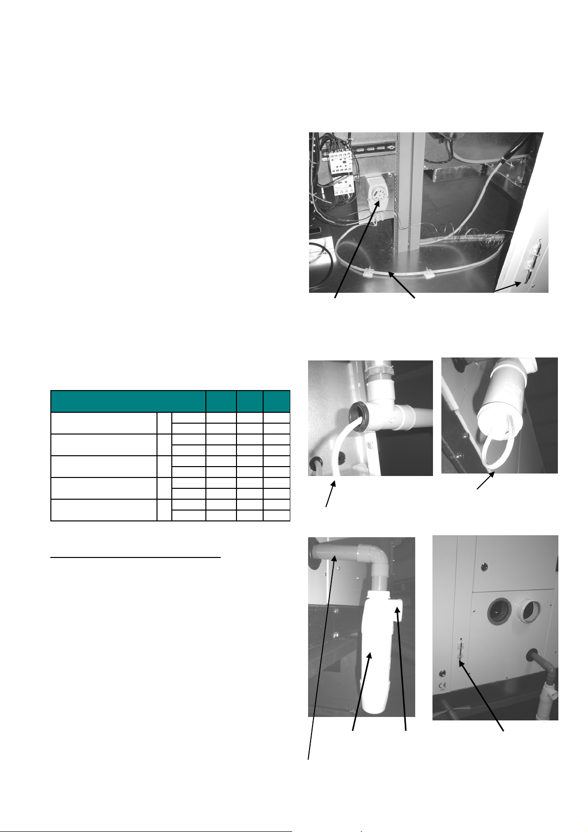
Figure 5a
Antifrost thermostat
inside unit to be set
at 3 - 5°C
Electrical heating
resistance
External sensor for
antifrost thermostat
Figure 5b Figure 5c
Electrical heating resistance
Electrical heating resistance
positioned inside condensate
trap
Figuur 5d Figuur 5e
Condensate trap
(option nr OP928)
Dia 32mm connection
Connection for PVC
tube dia 40mm
Sensor
thermostat
1210SHH_AMEN,page 8/29
Page 9
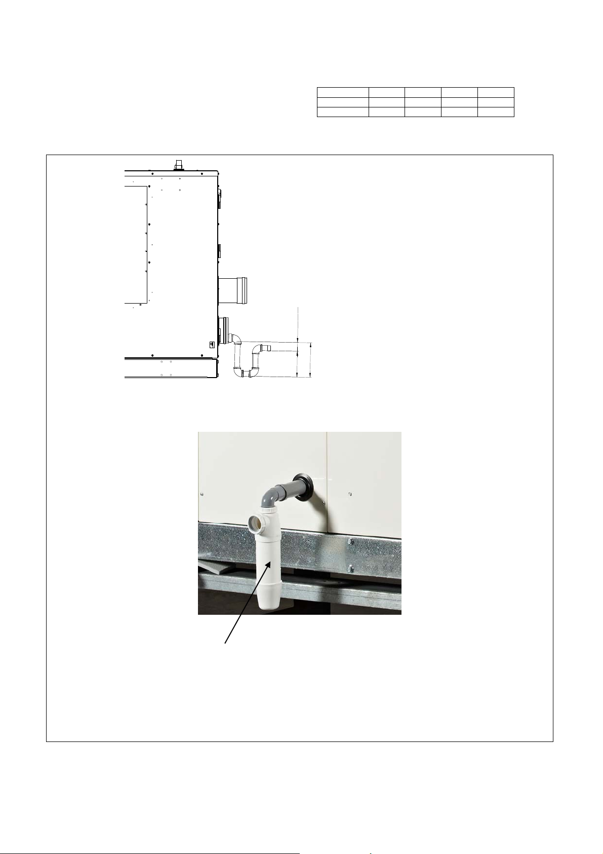
A PVC tube with collar of dia 32 is provided to drain the
condensate from the heat exchanger. Th e condensate
trap is optional.
REMARK : Fill condensate trap with clean water be fore
commissioning the unit.
Figure 6
Ensure that dimensioning of cond ensate drain can
handle condense rates as indicated below.
Condense drain rates of flow
BSHH 055 083 102
Nat. gas l/h 22 33 41
Propane l/h 13 19 24
m
m
0
5
n
i
m
C
D
C = D + minimum 50mm (= min. 180mm)
D = minimum 130mm
Condensate trap (option nr OP928)
1403BSHH_AMEN,page 9/29
Page 10
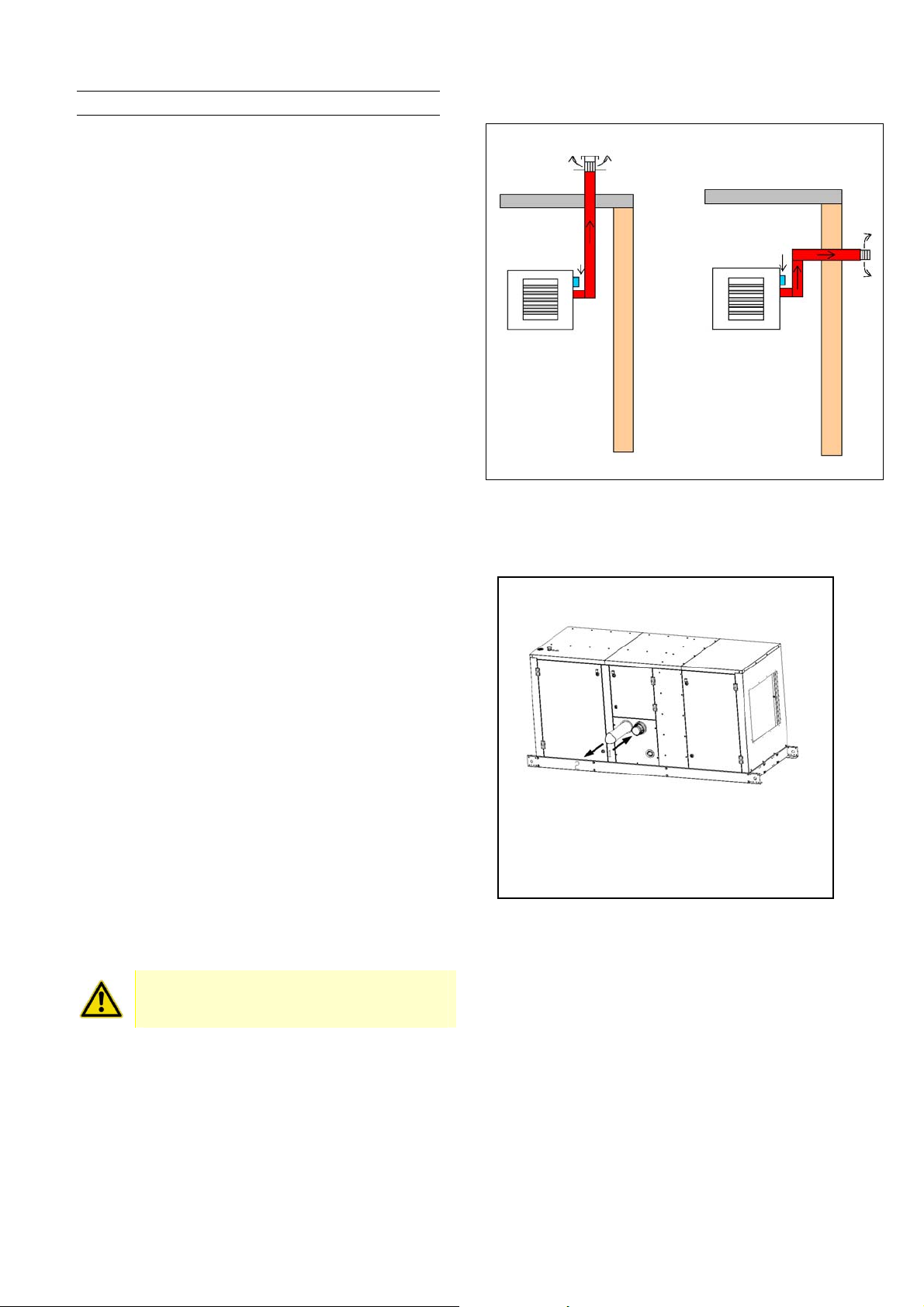
6.2 Type B appliances
6.2.1 Flues for power vented installations
If the air heater is to be installed as a type B appliance,
air for combustion will be taken from within the space
where the heater is installed.
Single wall flue seamless aluminium or stainless steel
pipes are required. All joints must be sealed to prevent
products of combustion from leaking into the buil ding. If
the flue passes through a combustible element of the
building it must be enclosed by a sleeve of noncombustible material and separated from the sleeve by a
minimum of 25 mm air break. The temperature of any
combustible material near to the flue must not exceed
65°C when the heater is in operation. The flu e must be at
least 150 mm away from any combustible materi al.
Single wall flue pipe exposed to cold air or run through
unheated areas should be insulated. Where
condensation is unavoidable, provision m ust be made for
the condensation to flow freely to a point to which it can
be released, i.e. a drain or gully. The condensatio n drain
from the flue must be constructed from non-corrodible
material not less than 20 mm diameter. Copper or copper
based alloys must not be used for co ndensation drains.
For testing, the flue pipe should include a sealable test
port. The port must be at least 450 mm awa y from the air
heater flue connection socket.
Follow the flue pipe manufacturer’s installation
instructions for making joints, including connections to
the air heater, for passing through a building element
and for support requirements.
6.2.2 Air supply
Ensure that an adequate air supply for combustion and
ventilation is provided within the building in accordance
with BS6230/BS5440 plus other relevant regulations &
rules in force.
It is important to ensure that there is an adequate air
supply at all times for both combustion and heating
requirements.
Modern buildings involve greater use of insulation,
improved vapour barriers, and weather proofing. These
practices mean that buildings are sealed much tighter
than in the past.
Proper combustion air supply for a power vented Type B
installation requires ventilation of the heated space.
Natural infiltration of air may not be adequate. Use of
exhaust fans aggravates this situation. It is important to
ensure that there is adequate combustion air supply at
all times. Reliance on doors and windows is not allowed.
Ensure that the air combustion inl et opening at the side of
the unit cannot be obstructed (cfr. fig 7b).
When these air heaters are installed in type B
applications, designed to take air for com bustion
from the space in which it is installed. Do not
restrict the combustion air intake.
Figure 7a : Approve d appliances ty pe B
B52/B22* – Roof
B52/B22* – Wall
* : only Belgium
Figure 7b : Type B appli ances – Combus tion air and
flue pipe sockets
1 Combustion air inlet opening
2 Flue pipe outlet collar
1210SHH_AMEN,page 10/29
Page 11
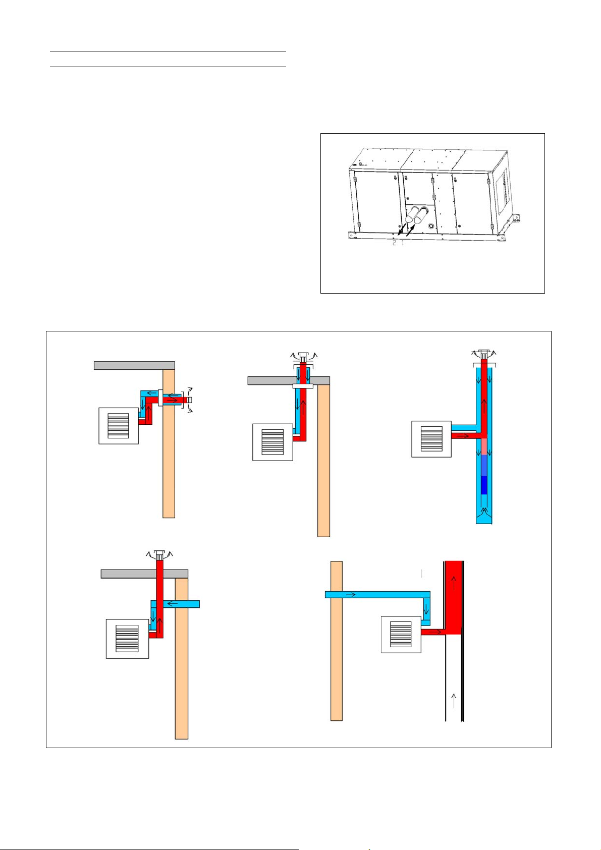
6.3 Type C appliances
Balanced flue air heaters are designed to be fitted with a
combustion air inlet duct that obtains outdoor air and a
flue pipe that exhausts flue products to outdoors.
Single wall flue seamless aluminium or stainless steel
pipes are required. All joints must be sealed to prevent
products of combustion from leaking into the buil ding. If
the flue passes through a combustible element of the
building it must be enclosed by a sleeve of noncombustible material and separated from the sleeve by a
minimum of 25 mm air break. The temperature of any
combustible material near to the flue must not exceed
65°C when the heater is in operation. The flu e must be at
least 150 mm away from any combustible materi al.
Single wall flue pipe exposed to cold air or run through
unheated areas should be insulated. Where
condensation is unavoidable, provision m ust be made for
the condensation to flow freely to a point to which it can
be released, i.e. a drain or gully. The condensatio n drain
from the flue must be constructed from non-corrodible
material not less than 20 mm diameter. Copper or copper
based alloys must not be used for co ndensation drains.
For testing, the flue pipe should include a sealable test
port. The port must be at least 450 mm awa y from the air
heater flue connection socket.
Figure 8b : Approved a ppliances type C
C12
C32
Follow the flue pipe manufacturer’s installation
instructions for making joints, including connections to
the air heater, for passing through a building element
and for support requirements.
Type C2 appliances must not be applied !
Figure 8a : Type C appliances - Combustion air and
flue pipe sockets
1 Combustion air inlet opening
2 Flue pipe outlet collar
C42
C52
C82
Concentric wall or roof terminal needs to be Mugro type 2000 (M&G) or Burfix (dia 100 or dia 130)
1403BSHH_AMEN,page 11/29
Page 12
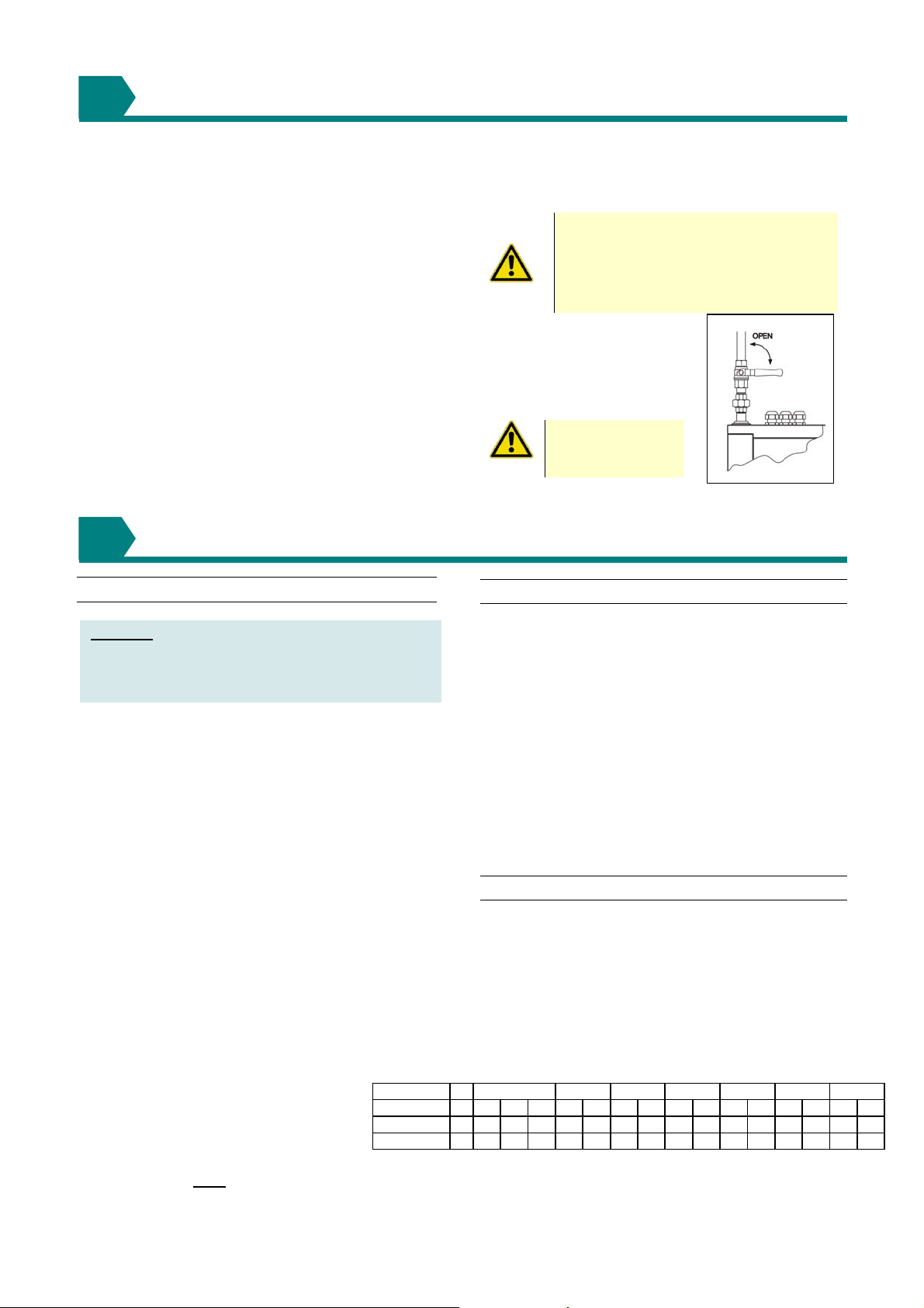
7
Connection to a gas service may only be carried out by
suitably qualified persons. All piping must be in
accordance with requirements outlined in the National
Gas Codes (different for each country). Gas supply
piping installation should also conform to good practice
and any local codes. Support gas piping with pipe
hangers, metal strapping, o r other suitable mate rial.
All sealing products shall be resistant to the action of
liquefied petroleum gas or any other chemical
constituents of the gas being supplied. Install a ground
joint union and manual shutoff the g as cock upstream of
the unit control system (see figure 9). The unit is
equipped with a nipple that extends outsid e the cabinet.
The gas connection is 3/4”. Leak test all connections by
brushing on a leak detecting solution. Check that the
gas category is in accordance with the data described
on the air heater. An adequate gas supply sized to
provide the dynamic pressure for the vol ume required by
the air heater(s) is essential to maintain the nominal
heat input.
GAS CONNECTION
Do not rely on the unit to support the gas
pipe!
8
ELECTRICAL CONNECTION
8.1 Electrical supply & connections
Atten ti on: Serious damage can occur to burner
relay when faulty connection of thermostat, reset
switch or burner failure lamp. Switching of wires
for reset switch and flame failure (e.g. in a remote
control box) will destroy the burner relay.
The electrical installation may onl y be carried out by an
appropriately qualified person current to IEE
Regulations. The supply line to the heater should
include a main switch adjacent to the appliance. The
minimum clearance distance betwe en the contacts must
be more than 3 mm. All electrical connectio ns should be
made in the heater control compartment (refer to figure
10). Connections should be in accordance with the
terminal markings and the wiring diagram affixed to the
air heater. The minimum external cont rol required for th e
air heater is a room thermostat. It is essential that the
main input line and neutral to terminals L and N
remain live at all times even when the heater is
switched off to ensure correct operation of the unit
and to let the fan operate independent of the heating
control. Never incorporate controls that isolate the
appliance electricall y.
A burner reset switch with red indicato r light is fitted on
the heater. To add a remote reset button, make
connections to the terminals in the electric box as
indicated on the wiring diagram.
IMPORTANT : If the reset button requires activating
for any reason, the cause must be deter mined. After
determining and correcting the problem, restart the
heater and monitor long enough to ensure proper
operation (approx. 5 minutes).
Check that the electrical specification is in
accordance with the specified data on the
air heater. A unique appliance wiring
diagram is supplied as a separate document
attached to this one plus an additio nal copy
attached to the air heater.
These appliances must
1210SHH_AMEN,page 12/29
be earthed.
Motor rating kW
Phase
Voltage
Load rating
V 230 230 400 230 400 230 400 230 400 230 400 230 400 230 400
A 5,2 3,3 1,9 4,5 2,6 5,9 3,4 8,3 4,8 11 6,5 15 8,6 19 11
~133333333333333
Ensure that a gas supply line includes a filter and has
been tested and purged in accordance with prescribed
practice prior to commissioning and taking the ai r heater
into service.
Figure 9 :
Gas connection detail
This appliance is equipped for a
maximum gas supply pressure of
50mbar. Pressure testing supply piping:
test pressures above 50mbar:
disconnect the heater and manual valve
from the gas supply line that is to be
tested. Cap or plug the supply line..
NEVER use a
FLAME
to test for GAS
SOUNDNESS !
8.2 Thermostat controls
Ancillary controls are required to provide timed heat
cycles, room comfort temperature level, frost protection,
override air circulation etc. These are not included with
the appliance and should be ordered separa tely.
Do not attempt to control more than 1 air heater from
a single thermostat or control panel unless a prope rly
wired relay is fitted. Follow the instructions supplied
with such panels.
The location of the room thermostat or sensor is very
important. It should not be positioned on a cold wall or
cold surface. Avoid location in draughty areas or where it
may be influenced by heat sources e.g. the sun, process
plant, etc. The thermostat should be mounted on a
vibration free surface and mounted about 1,5 metres
above floor level. Follow the thermostat manufacturers
instructions. The thermostat must be suitable for
potential free contacts.
8.3 Fan motors
The centrifugal blowers fitted to the BSHH/RHH air
heaters are of the forward curved type therefore, the
speed setting for the static pressure imposed by the air
distribution system will govern the motor loading. All
heaters leave the factory with the drives set to the
specified conditions of the appliance. Table 4 provides
the motor characteristics for the various sizes. Refer to
section 9 to learn how to carry out adjus tments necessary
to alter the fan speed and motor load factors.
Table 4 : Maximum motor load rating
345,50,75(1) 1,1 1,5 2,2
(1) only possible on 083 model
Page 13
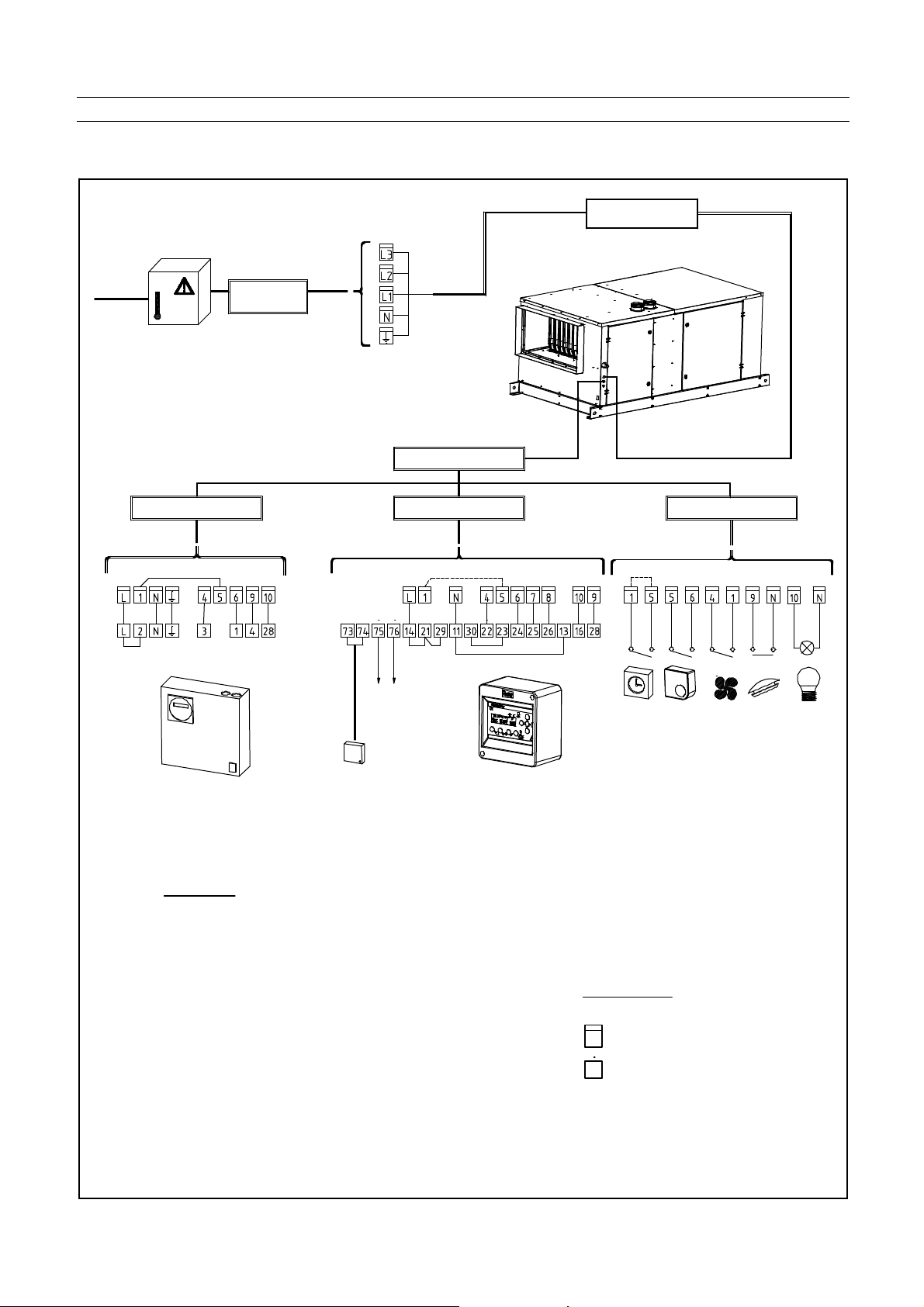
8.4 Wiring connections on the ter minal board
Not
Figure 10 :
Mains Isolator Must be installed within
1 metre of the appliance
3 phase
415V 3N 50Hz
AS1
J1
240V
Permanent
M a ins Su ppl y
External Controls
Energymizor Mk3
230V
Low
Voltage
Thermistor Ro om
or Duct Sensor
Slave / Ma ster
Connections
(If Required)
J1
Power Supply
J1
240V
Time control
thermostat
O t h er C ontr ol s
Fan only facility
Room/Duct
Lock-out reset
Lock-out lam p
(240V)
es:
Remove link wir es shown dotted
1.
Retain/ins ert link wires shown solid
2.
Term inals shown may not be in
3.
nume rrical order . Unused terminals
may not be shown at all.
1 Phase supply cable 2,5 mm
4.
minimum.
Controls cables 0,75 mm for
5.
up to 200 metre run.
Energymizor Sensor cable
6.
0 ,25 mm (sc reened)
7.
Ma ster/sl ave ca ble 0,1mm,
bell wire type (no scree n
necessary)
Fuse ra ting must be sufficiently
8.
sized to handle heater & mo tor
loadings.
Legend:
Heater ter minals
Contr ols terminals
1403BSHH_AMEN,page 13/29
Page 14

9
COMMISSIONING, LIGHTING and OPERATION
9.1 Commissioning
Normally BSHH air heaters do not require
commissioning. Final testing after production ensures
that, if installation has been carried out by a suitably
qualified person and strictly in accordance with this
document, the appliance is ready to be taken into
service.
9.1.1 Check
Prior to start up heater, carry out follow ing checks to
ensure :
o Check suspension . Unit must be secure. Verify th at
no other parts are fitted which are not individually
supported and secured.
o Check piping f or leaks and proper gas line pressure.
Bleed gas lines of trapped air.
o Check electrical wiring and ensure that wiring
conforms to the wiring diagram. Be sure all wire
sizes meet requirements.
o Phase supply cable to correct terminals.
o Check polarity. Verify that line voltage exists
between the black “L1” and earth ground.
o Verify that t he appliance is earthed by conducting a n
earth continuity test.
o Current rating and fuse value.
o Correct supply gas pressure.
o Correct bur ner gas pressure.
o Satisfacto ry & smooth ignition.
Supplementary checks in case of an BSHH
installation
o Check clearances from combustibles. Requirements
are in section 5.
o Check vent system to be sure that it is installed
according to the instructions in section 6, venting
requirements.
o Check if condensate drain trap is filled with clean
water.
9.1.2 Heater start-up
o This heater does not have a pilot flame. It is
equipped with an ignition device that autom atically
lights the burner. Do not try to light the burner by
hand.
o Before operating, smell all around the heater area
for gas. Be sure to smell next to t he floor because
propane gas is heavier than air and will settle near
the floor.
o Do not use this appliance if an y part has subjected
to water ingress. Immediately call a qualified
service technician to inspect the appliance and to
replace any part of the control s ystem and any gas
control.
s
:
For your safety, follow the instructions
exactly otherwise damage or injury
could occur !
o When overheating occurs or when gas supply is not
turned off, shut the manual gas tap before turning
off the electric power.
o In addition to the above requirements checks to
ensure that the fan performance and motor load
factors are correct for the application and in
accordance with the appliance dat a plate.
9.1.3 Drives : general and adjustmen ts
Adjustment may be necessary to set the fa n duty for the
static pressure and motor load requirements. Before
starting work on the fan assembly:
o Set extern al controls to off or their lowest setting.
o Turn OFF
o Switch OFF
after the air circulating fan ha s stopped.
o Carry out adjustments as appropriate.
. Rotational speed checks should be carried out
N.B
using an infrared tachometer or stroboscope.
Adjusting the fan speed can be carried out by altering
the diameter of the adjustable drive pulley on the motor
shaft.
o Loosen the belt tension device and remove he
drive belt.
o Refer to figure 11 and note that the out er section
of the drive pulley is secured by a hexagon socket
screw to a flat on the pulley hub, this is positioned
by loosening the hexagon socket screw
sufficiently to enable the pulley to be either
opened or closed by turning it on the thread on
which it is engaged.
o It should be noted that one complete turn of the
pulley half is equal to approximatel y 8% of the fan
speed. Closing the pulley increases th e speed and
opening decreases the speed.
o After making speed adjustments tension belt in
accordance with the dimensions given in figure
11 and check pulley alignment to ensure the belt
runs correctly.
. Always ensure that the pulley is tightened onto a
N.B
flat of the hub before switching on the fan, even when
testing a reset condition.
If the amount of adjustment is not achieved with the
range obtainable with the pulleys fitted, it will be
necessary to change the driven pulley fitted on the
blower and possibly the size of the drive V belt. After
adjustment ensure the motor l oad rating is not e xceeded!
the gas supply to the air heater.
the electricity supply to the air heater
Opening the pulley too far will cause the belt to
touch the bottom of the V grove resulting in a
significant reduction of belt life time and l oss of
grip.
1210SHH_AMEN,page 14/29
Page 15
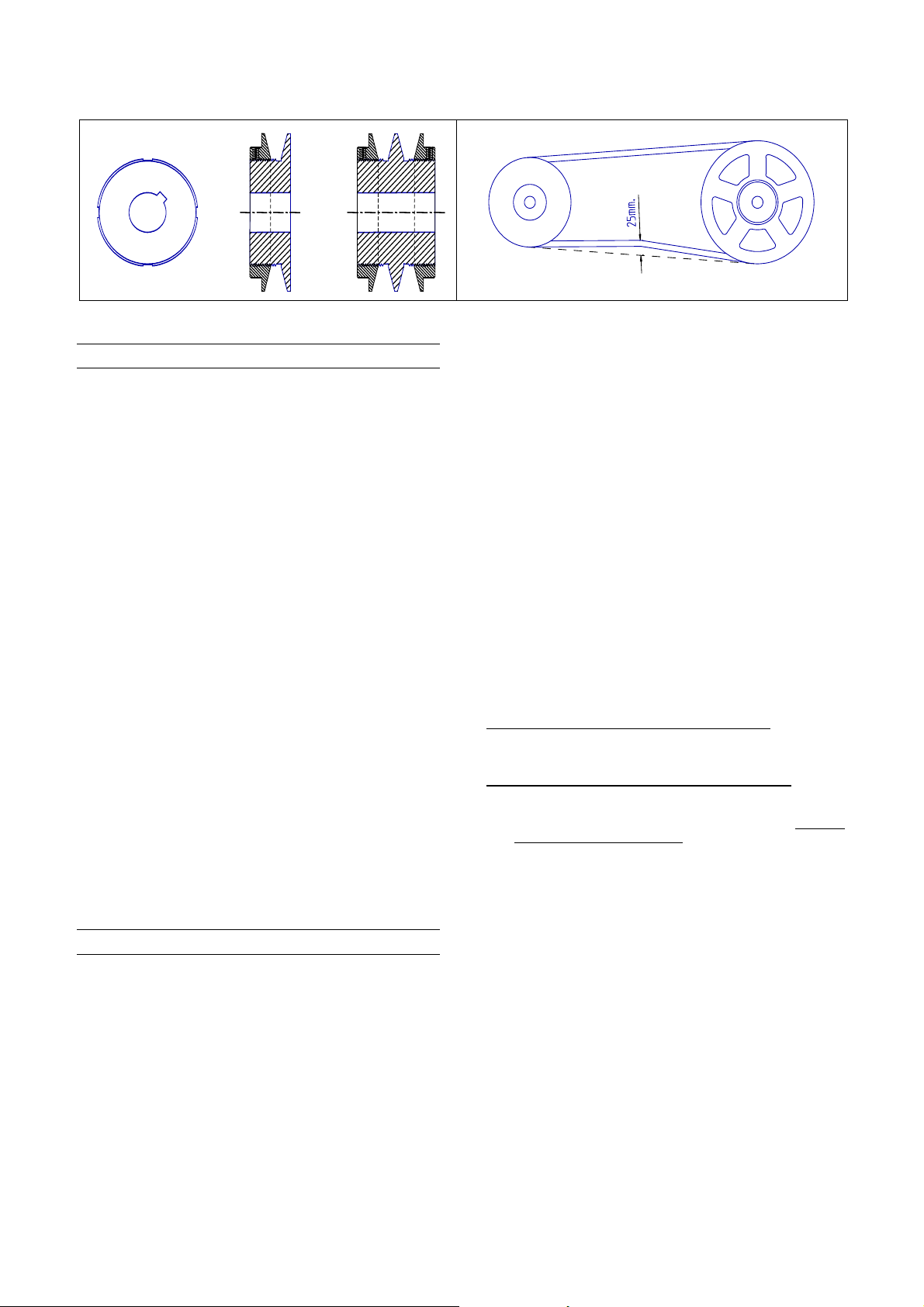
Figure 11 : Pulley and dr ive belt adjustmen t
9.2 Ignition system
o Ensure that air discharge louvers are set to open.
o Switch on electrical sup ply.
o Turn on gas suppl y.
o Set tim e switch (if fitted) to an 'ON' cycle.
o Set room thermostat to 'ON' position.
o If reset bu tton on heater and/or on remote control (if
fitted) lights up, press reset button.
o Thermostat calls for heat, energizing the venter
motor.
o When adequate airflow for combustion is proven by
an air proving switch and a prepurge period has
elapsed, the integral igniter and multifunctional gas
control operate. The ignition spark ignites the gas
creating the burner flame.
o Burner flame is sensed by a flame rod sensor and
when the heat exchanger is warmed up (+/- 30
seconds) and the fan control relay closes, the fan
motor is energized.
o If the flame is extinguished during the main burner
operation, the integrated control system closes the
main valve and attempts to relight the burner. The
unit will attempt 5 ignitions before entering a “lock
out” mode. Lock out is indicated by the red warning
light on the heater. To end this mode push on the
reset switch.
o For a new installation or if the appliance has been
turned off for an extended period then up to 3
attempts to light the air heater may be necessary. If
the heater still does not light, consult the faultfinding guide.
9.3 Operation
In case of a not continuous running fan (= ventilation),
simultaneously to the ignition circuit and gas valve circuit
being energised, electrical power is supplied to a time
delay relay that will activate the fan. The air circulation
fan will start after about 20 à 60 seconds.
In the event of the combustion air volume fa lling below a
safe level, the burner will be extinguished a re-start cycl e
will commence after adequate combustion air volume has
been restored.
If the burner flame is extinguished fo r any reason during
a run cycle, an automatic attempt for re -ignition will take
place, if the burner does not relight after 5 attempts,
then safety shut down and lockout will occur. Manual
intervention to reset is necessary to put the air heater
back into service.
In the event of overheating for any reason, thermally
activated fail safe overheat controls operate to switch off
the burner.
The overheat control (LC3), will switch off the burner and
itself set to a lockout condition which also requires
manual intervention to reset to restore the heater to
operational condition. A cooling time of 1 minute is
necessary before thermal re-s etting can be carried out
When the set temperature or the heating tim e period has
been reached, electrical power to the burner rel ay will be
switched off and the burner will ex tinguish. In case of a
not continuous running fan, the air fan will continue to
run for about 60 – 120 seconds until th e heat exchanger
has been cooled down to a safe l evel.
To turn off the air heater for a short per iod
a) turn room thermostat to lowe st setting.
b) to relight reset thermostat.
To turn off the air heater for prolonged period
a) turn room thermostat to low setting or ‘OFF’ position
b ) shut off gas supply to th e appliance
c) switch off electricity suppl y to the air heater after air
circulation fan has stopped.
d) to relight follow lighting instructions.
The gas service tap must only be operated in
emergencies, for servicing or prolonged periods of
shutdown of the air heater .
,
;
1403BSHH_AMEN,page 15/29
Page 16
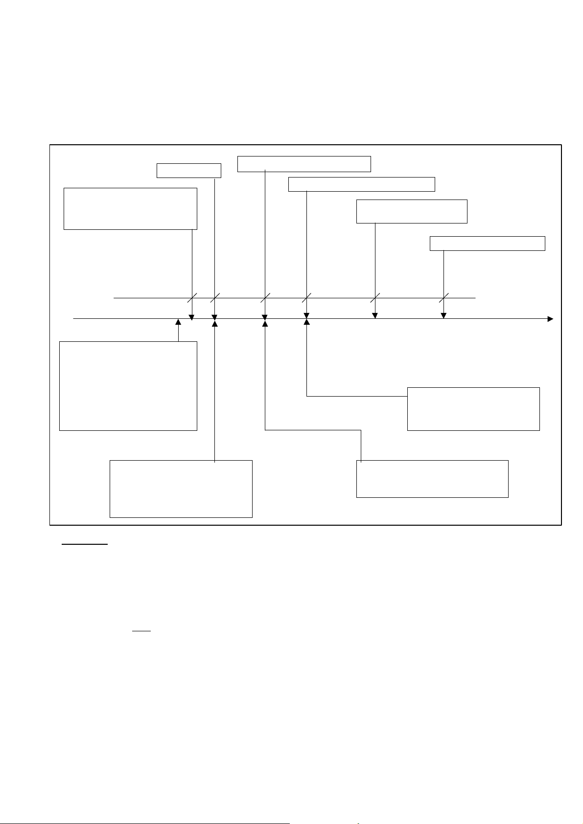
Figure 12 : Ignition system
The BSHH heater is equipped with a direct spark integrated control relay. The control rela y monitors the safety devices
and controls the operation of the venter motor an d the gas valve between heat cycles.
The time line below illustrates a normal heat cycle.
The time line below illustrat es a normal heat cycle.
Sta rt pr e- pu rg e
Ene r gi sa t io n of ve nt er mot or .
If the differential pressure switch
is in normally closed position
(start position).
Start position
Fir st he at de m and sign al .
Check on pressure switch.
Must be i n cl o se d or st ar t pos iti on .
If not, there will be no power to
the venter motor.
The power to the burner relay is off
until the pressure switch goes to
normally closed - or start position.
Power to gas valve and i gnitor
Sens or checks for the presence of a flame
En d of heat dem and .
De-e n er gi s at io n of ga s va l ve .
Ignition
time=
Pre-purge
time
Safety
time
Normal operation
of burner relay
Post -p ur g e ti me
20 se c 5 se c 10 se c
De-energisation of ven t er motor
time
If no flame, then repeat starting
at pre-purge fo r 5 attempts.
If no i on is at i on af te r 5 a tt e mp ts, th en
lock-out.
Safety check on flame sensor.
If there is a flame, the relay will
go to lock-out. The light in the red reset
Line output during ignition time to control
high fire start on two stage or modulation
applications.
switch, mounted visi bly on the heater
will glow.
Definitions
•Start position: The system is not in locko ut position and can p roceed with the start-u p sequence upon a de mand for
•Pre-purge time: This is a period of 20 seconds during which the combustion fan (venter) operates prior to activation
•Safety time: The safety time is the delay between the g as valve being energized a nd the flame sensor checking
Note
•Post-purge time: This is the time of 10 seconds between burner shutdo wn and the moment th e combustion fan (venter )
heat.
of the ignition device.
for the presence of a flame. This is a period of 5 s econds.
: If no flame is sensed, the burner relay will attempt ignition 5 times before going into lock-
out mode.
is de-energized.
1210SHH_AMEN,page 16/29
Page 17
9.4 Burner gas pressure adjustment
The gas pressure is set for the required heat input b efore
the appliance leaves the factory. Provided that the gas
supply to the air heater is in accordance with the supply
pressure described on the appliance data plate, the
operating pressure will not require adjustment.
To check the pressure use the following procedure:
o Ascertain from the heater’s data plate the correct
operating gas pressure;
o Turn the room thermostat control to its lowest
setting;
o Connect a manometer to the test point on the gas
manifold;
o Adjust the room thermostat to call for heat i.e. above
room ambient temperature;
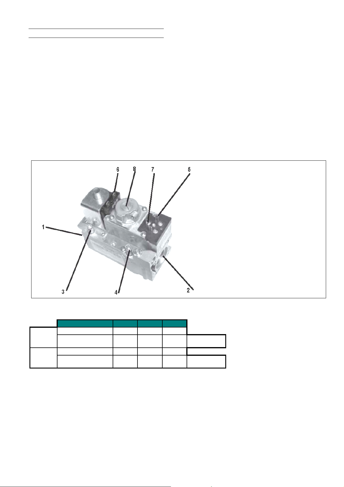
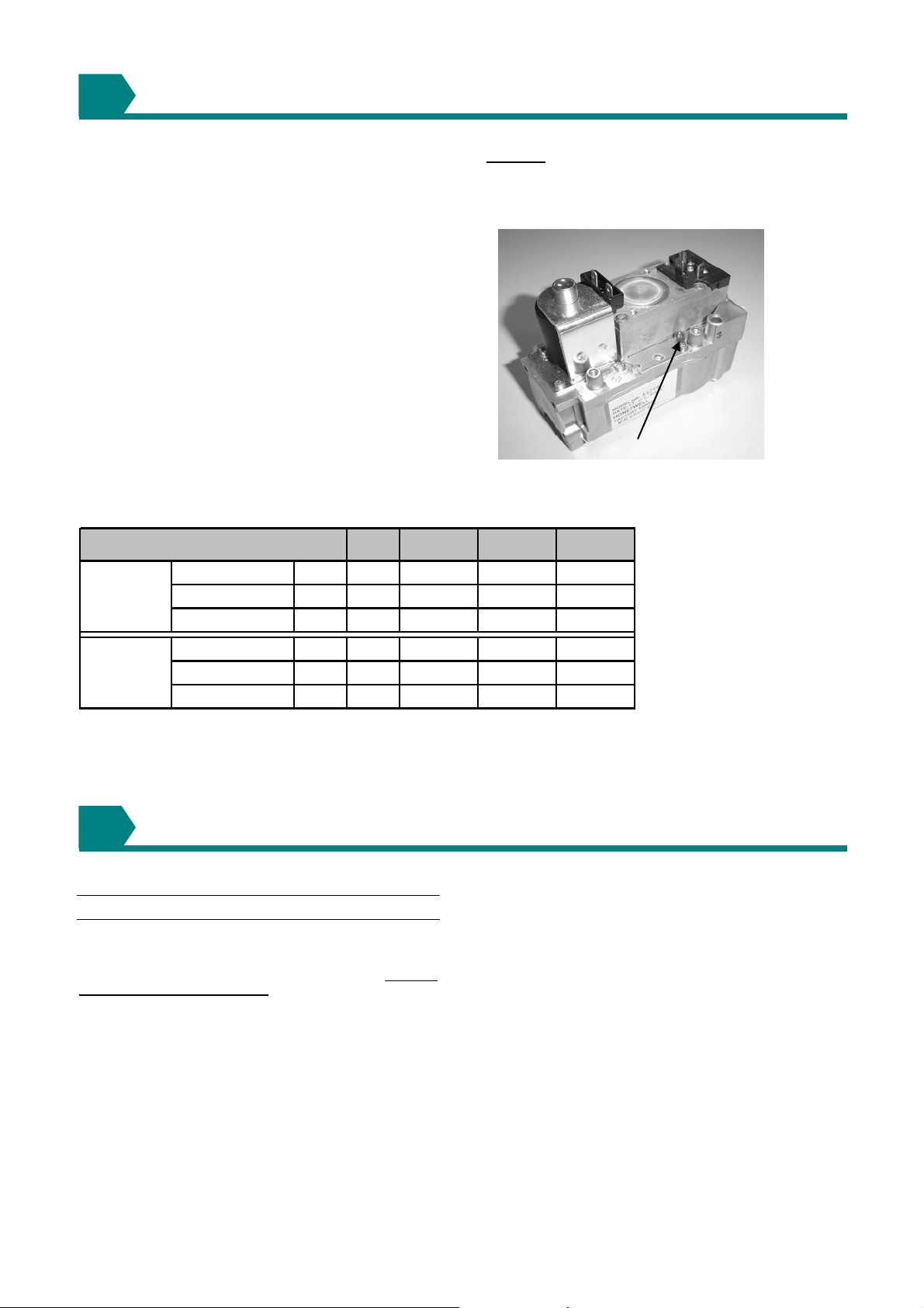
Figure 13: Honeywell gas valve
o Observe the burner gas pressure on the manometer
and compare to the required pressure on the data
plate;
o If nec essary, adjust the burner gas pressure. Remove
the cover screw. Turn the regulator screw anticlockwise to decrease pressure or clockwise to
increase pressure (see figure 13). A djusting the burner
pressure may only be carried ou t by suitably qualified
persons.
o Set room thermostat to lowest setting to turn OFF the
burners. Replace the test poi nt screw/cap and with the
main burner OFF, test for gas soundness using a leak
detector fluid.
Reset temperature control/room thermostat to comfort
operating level.
1) Gas inlet
2) Gas outlet
3) Inlet pressure tap
4) Outlet pressure tap
5) 6.3mm AMP terminals and screws for wiring
6) 6.3mm AMP terminals
7) Earth terminal/screw (line voltage models only)
8) Pressure regulator adjustment screw
Table 5 : Burner jets and press ures
BSHH
Nat Gas
G20
Prop Gas
G31
Burner jet dia 6,80 7 , 60 8,40
Burner pressure mbar 8,30 10, 40 8,80
Burner jet dia 4,50 4 , 50 5,60
Burner pressure mbar 15,70 34,36 23,50
055 083 102
inlet pressure
20 mbar
inlet pressure
37 mbar (*)
1403BSHH_AMEN,page 17/29
Page 18
10
TWO STAGE BURNERS SETTING & ADJUSTMENT
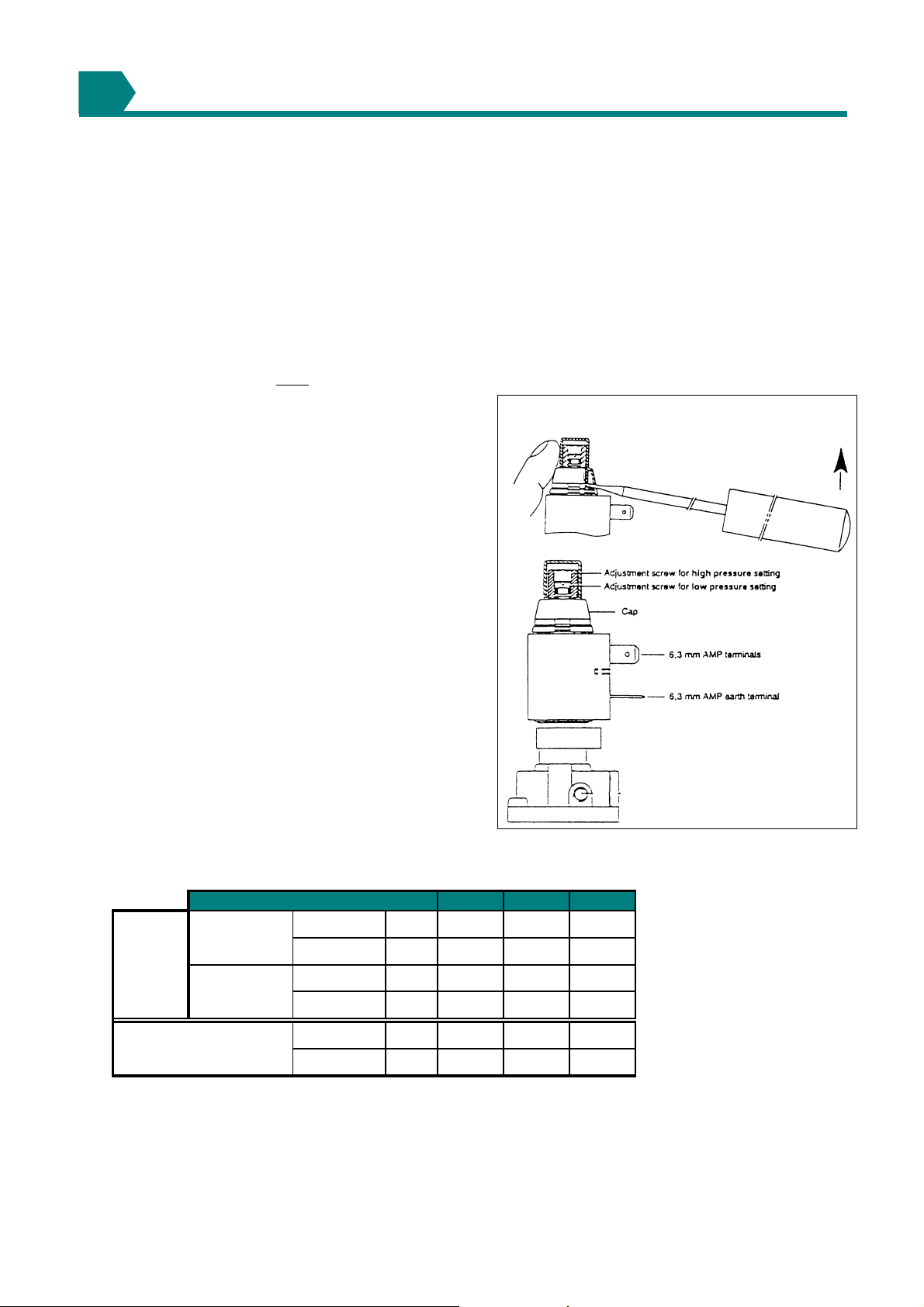
The BSHH air heaters can be optionally equipped with
two stage burners. The type of gas control fitted is the
"Honeywell" VR 4601P/B or VR 4601A/B either a re fitted
with a two-stage pressure governor model V4336A.
Regulation is possible for the pressure range 1,5 - 20
mbar for natural gas and 4 -37 mbar for propane gas.
The appliances are fitted with a relay to ensure that
during burner start-up the initial firing rate is 100% to
ensure good burner cross lighting.
Adjusting the burner pressure may only be carried out
by suitably qualified persons.
Setting (refer to figure 14) :
Allow time for pressure to stabilise before and during
making adjustments.
a. Leve r off the plastic cover c ap
b. Maxim um high rate setting must
first after which the minimum low ra te setting can be
adjusted. Any adjustment of the maximum setting
influences the minimum setting.
c. Do not adjust maximum or minimum setti ngs above
or below the pressures stated on the air heater data
plate.
Adjusting maximum pressure setting :
a. Energise high/low regulator, set gas control in
operation and wait until an outlet pressure is
recorded on pressure gauge.
b. Use a 10 mm screwdriver to turn adjustment screw
for maximum pressure setting clockwise to increase
and counter-clockwise to decrease pressure until
desired maximum pressure is obtaine d.
c. Check maximum pressure setting several times.
Table 6 : High/low burner gas pr essures and low rate co nsumption values
Pressure @
Burner
pressure
100%
Pressure @
50%
be adjusted
Model
nat. G20 mbar 8,30 10,40 8,80
prop. G31 mbar 15,70 34,26 23,50
nat. G20 mbar 2,08 2,60 2,20
prop. G31 mbar 3, 92 8,59 5,87
Adjusting minimum pressure setting :
a. Disconnect electrical connection of high/low
regulator.
b. Set gas control in operation and wait until an
outlet pressure is recorded on pressure gauge.
c. If minimum pressure setting needs adjustment
then use a 3.5 mm screwdriver to turn adjustment
screw for minimum pressure setting, clockwise to
increase or counter-clockwise to decrease
pressure, until desired minimum pressure setting
is obtained.
d. Wire high/low regulator in circuit.
e. Check maximum pressure setting, re-adjust if
necessary and check minimum pressure again.
Figure 14 :
055 083 102
Gas consumption @ 50%
Ref. 15°C, 1013mbar (1)
Note : burner pressures for propane gas s es are approx. Based on regulated supply pressure
(1) -
-
Low fire rate must not be reduced bel ow the values stated above for 50 % RATING
nat gas G20 net calorific value 34,02 MJ/m³ @ 15°C & 1013 m bar
prop gas G31 net calorific value 88,00 MJ/m³ @ 15°C & 1013 mbar
nat. G20 m³/h 2,79 4,18 5,13
prop. G31 kg/ h 1,08 1,61 1,98
1210SHH_AMEN,page 18/29
Page 19
11
GAS CONVERSION
This air heater is designed to operate on natural,
propane or butane gas and will be supplied as ordered
for the gas type specified. In the event it is required to
convert to a different gas type to that which has been
supplied, conversion of the gas burner must be carried
out. This can only be carried out by an appropriately
qualified person current to IEE regulations
An approved conversion kit to suit t he appropriate gas
type must be used.
In addition to changing the burner injectors, and
adjusting the burner gas pressure (pressure regulator
or throttle adjusting screw), for s ealing the governor or
the throttle adjusting screw it is necessary to fix data
plate over stickers as supplied with the conversion kit
of parts (propane see figu re 15).
After conversion re-commission appli ance according to
section 9 of this document.
Table 7 : High/low burner gas pressures
Type
Injector dia (1x) m m 6,80 7,60 8,90
Natural
gas G20
burner pressure 100% mbar 8,30 10,40 8,80
burner pressure 50% mbar 2,08 2,60 2,20
Remark:
high percentage of b utane can caus e sooting of t he
heat exchanger.
Figure 15
Always check the propane gas quality, a too
055 083 102
Throttle adjustment screw
Propane
gas G31
burner pressure 100% mbar 15,70 34,36 23,50
burner pressure 50% mbar 3,92 8,59 5,87
Injector dia (1x) m m 4,50 4,50 5,60
12
MAINTENANCE & SERVICE
12.1 Maintenance schedule
General:
Before commencing servicing, turn off the main gas
supply and switch off the main elec tricity supply after the
air circulation fan has stopped.
The heater will operate with a mi nimum of maintenance.
It is recommended that maintenance is carried out at
least once a year by a suitably qualified person. More
frequent servicing may be required dependent upon the
environmental circumstances where the air heater is
installed. Regular inspection is necessary, especially in
dirty areas, to assess the servicing fr equency.
Check condition and security of flue and combustion air
system.
Check for security and worthiness of the suspension or
mounting system.
Maintenance Schedule:
The following procedures should be carried out at least
once each year (see figure 16).
• Clean all dirt, lint, and gre ase from the fan and motor.
• Check the heat exchanger an d externally for evidence
of physical damage.
• Check the burner for scale, dust, or lint ac cumulation.
Clean if required.
• Check the vent or vent/combustion air system for
soundness. Replace any parts that do not appear
sound.
• Check the wiring for any damage. Replace damaged
wiring.
1403BSHH_AMEN,page 19/29
Page 20
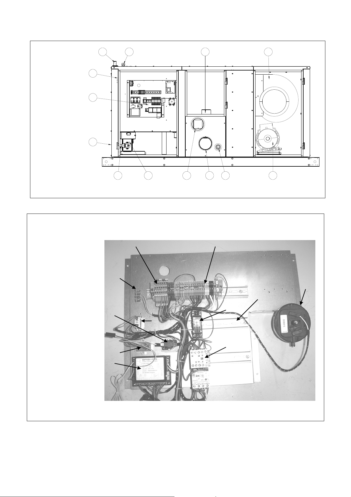
Figure 16a : Location components BSHH models
4
1. Burner lockout
indicator/reset
button
2. Wiring panel
3. Capillary thermal
overheat control
with manual
reset (LC3)
4. Gas connection
5. Cable entry
connections
6. Combustion flue
gas extraction
fan with motor
7. Blower
8. Motor
9. Drain
10. Combustion air
inlet
11. Flue gas outlet
12. Burner box
assembly
13. Gas manifold
injector & test
point
3
2
1
Figure 16b :Detail wiring pane l
5 76
1213
11
10
89
Components
14. Electronic burner
controller
15. Interference
suppresser filter
16. Time delay relay
17. Earthing
18. Wiring terminals for
electrical controls
19. Relay two stage (**)
20. Motor starter
21. Differential pressure
switch (flue gas)
22. Connexion supply
voltage
23. 24V relay (**)
24. GM44 (*) (**)
25. Relay
(*) = not illustrated
(**)= not standard
16
15
14
17
22
18
21
23
19
25
20
1210SHH_AMEN,page 20/29
Page 21
12.2 Heat exchanger maintenance
This heater is equipped with a T-CORE² heat e xchanger.
Remove any external dirt or dust accumulation. Visually
check the heat exchanger for cracks and holes. If a crack
or hole is observed, replace the heat exchanger.
A T-CORE² heat exchanger has a primary and secondary
heat exchanger – check both sections.
12.3 Burner maintenance
This heater has a unique one-piece T-CORE
assembly designed to provide controlled flame stability
without lifting or flashback. The burner can be remove d
as a unit for inspection or service : see below for
removal instructions.
Inspect the burner/control compartment annually to
determine if cleaning is necessary. If there is an
accumulation of dirt, dust, and/or lint, clean the
compartment and follow the instructions below to rem ove
and clean the burner.
Use of eye protection is recommended.
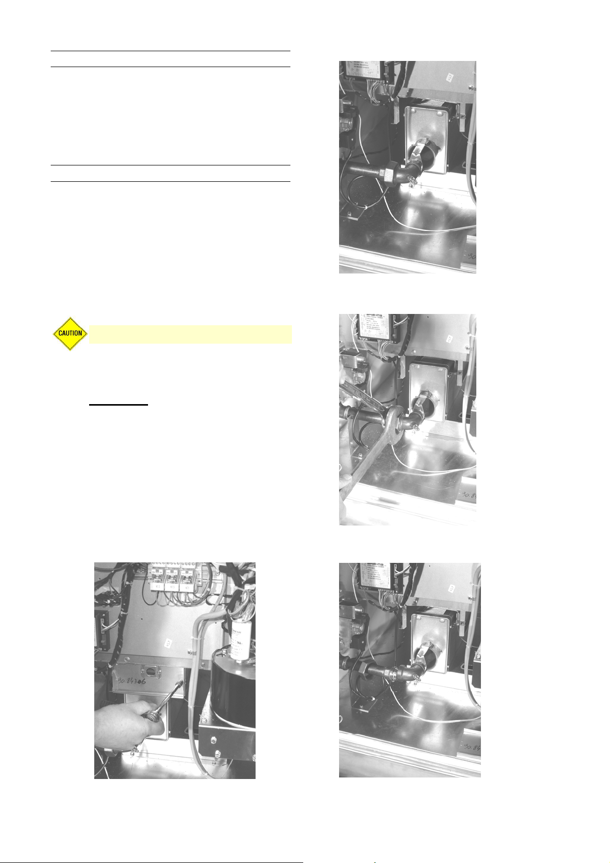
12.3.1 Burner removal :
®
2
burner
Figure 18
Figure 19
Disconnect gas manifold at the 90° elbow
Instructions
1. Outsid e the cabinet, shut the gas
2. Tu rn off the electric su pply.
3. Disco nnect the gas supply at the
4. Open the access door.
5. Remove burner :
Figure 17
Remove 2 screws of the burner shield
supply off at the manual valve
ahead of the union
union outside of the cabinet.
Figure 20
Gas manifold is split
1403BSHH_AMEN,page 21/29
Page 22
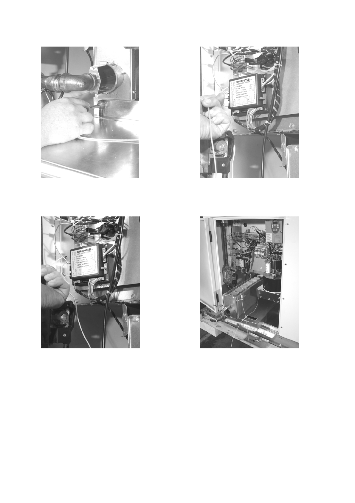
Figure 21 Figure 22
Remove 2 screws of the burner slider Disconnect wire o f the igniti on electrode at the
burner controller
Figure 23 Figure 24
Disconnect flame sensor wire at the burner controller Remove burner box (togeth er with flame sensor
and ignition electrode
1210SHH_AMEN,page 22/29
Page 23
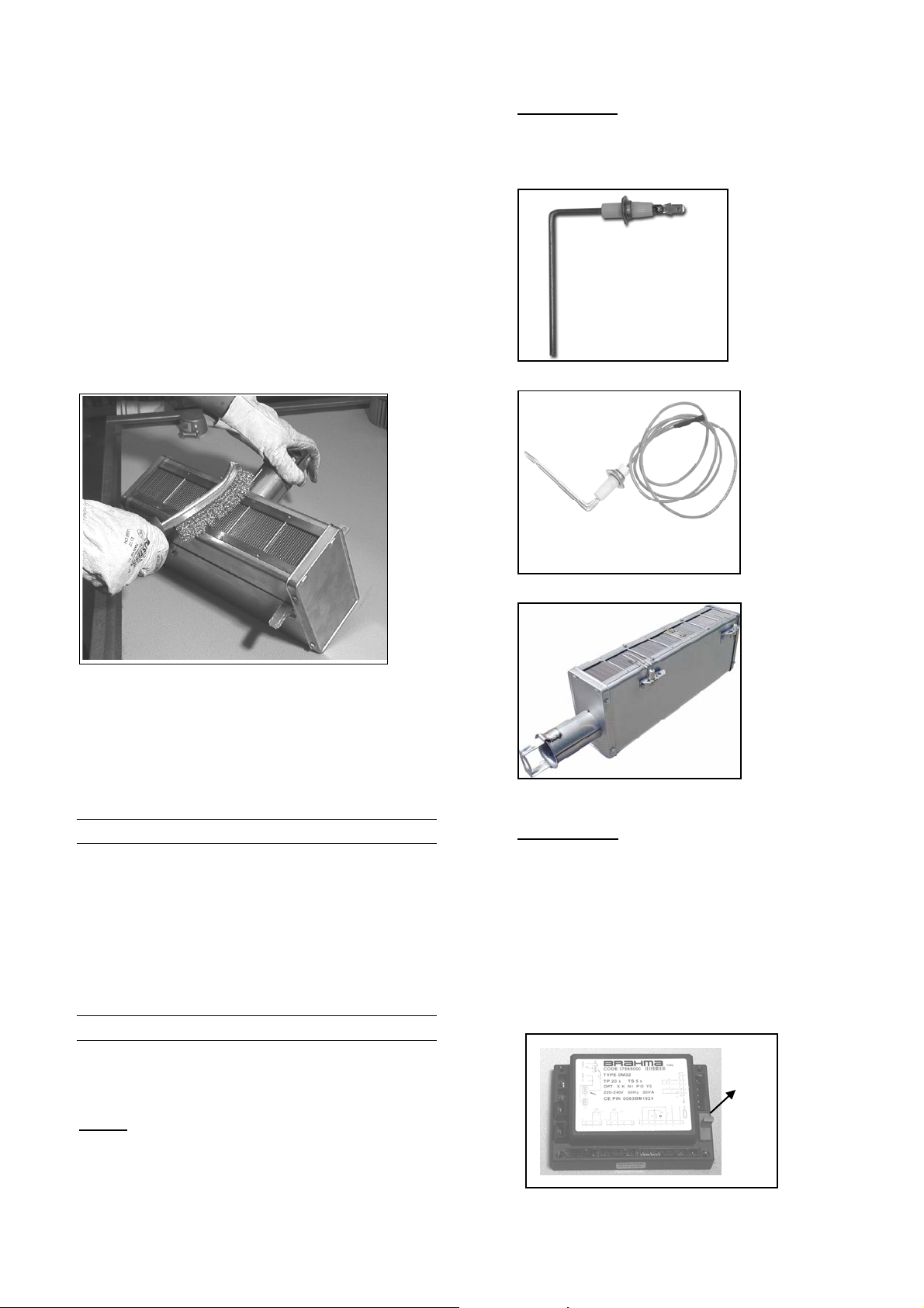
12.3.2 Inspect and clean the burner :
With the burner assembly removed, shine a flas hlight on
the burner ribbons. Look for carbon buildup, scale, dust,
lint, and/or anything that might restrict flow through the
spaces between the burner ribbons. Holding the burner
assembly so that any foreign material will fall away from
the burner, use a stiff bristle brush to loosen and
remove any foreign material(s). If the burner is
excessively dirty, remove one of the burner end caps.
Remove the four screws that hold the end cap to the
burner housing. Lightly tap the end cap to remove it.
Clean all foreign material from the burner and venturi.
Use pressurized air to clean complete ribbon tray of the
burner. After the burner is thoroughly clean, replace the
end cap making sure that it is tight against the burner
housing. NOTE: If any of the burner components are
damaged or deteriorated, replace the bu rner assembly.
Figure 25
Flame sensor - Refer to fig ure 16 and locate the
flame sensor. Disconnect the wire, remove the
screw and the flame sensor. Clean with an emery
cloth..
Figure 26 : Flame sensor
Figure 27 : Igniter
12.3.3 Reinstall the burner :
Repeat ‘Burner Removal’ steps above in the opposite
order.
12.4 Burner orifice
The burner orifice normally needs to be replaced only
when a change in gas is made. When ordering a
replacement orifice, provide (MJ/m3) heating value and
specific gravity of gas, as well as the model and serial
number of the unit. When removing or replacing the
burner orifice be careful not to damage t he venturi tube
and/or the bracket.
12.5 Ignition system
The igniter and flame sensor are fixed on the burner
body. For replacement burner bod y needs to be removed
(we here for refer to section 11.3 : Burner maintenance).
Igniter - Refer to figure 16 and locate the igniter.
Disconnect the wire; remove the screw and the igniter.
Clean the igniter assembly with an emery cloth.
Spark gap must be maintained to 3 m m.
Important: When reassembling, the wire must remain
attached to the igniter.
Figure 28 :Burner body
Control relay
burner relay monitors the operation of the heater
including ignition. Do not open the control relay.
Each heating season check the lead wires for
insulation deterioration and good conn ections.
Proper operation of the direct spark ignition system
requires a minimum flame signal of 1.0 micro am ps
(DC) as measured by a microampmeter.
For further information and check out procedure on
the direct spark ignition system and the
Troubleshooting Flow Chart.
Figure 29 : Control relay
- See figure 29. The electronic
Fuse
1403BSHH_AMEN,page 23/29
Page 24
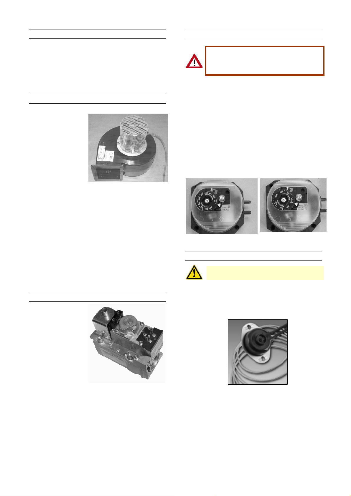
2.6 Fan motor, fan
The fan motor is equipped with thermal overload
protection of the automatic reset type. Should the m otor
fail to run, it may be because of improper voltage
characteristics. Make certain that the correct voltage is
available at the motor.
Remove dirt and grease from the motor and the fan. Use
care when cleaning the fan to prevent i mbalance.
12.7 Venter motor & wheel
Figure 30
Remove dirt and
grease from the motor
casing, the venter
housing, and the
venter wheel. Venter
motor bearings are
permanently lubricated. Follow these
instructions for replacement of the
venter motor and
wheel assembly. Keep all hardware removed to be
used in reassembling and installing the replacement
parts.
1. Turn off the gas and disconnect the electric po wer.
2. Open the control compartment acc ess door.
3. Disconnect the three venter motor wires at the
terminal and ground screw .
4. Holding the motor, remove the screws that attach
the motor plate to the venter housing. Remove the
motor and wheel assembly from the heater.
5. Reassemble with the replacement venter m otor and
wheel assembly.
6. Follow the wiring diagram to properly connect the
wires.
7. Restore power to the heater and turn on the gas.
Light, following the instructions on the lighting
instruction plate. Check for proper operatio n. Close
the access door.
12.8 Operating gas valve
See figure 31
The main operating
quick opening gas
valve is powered
through the
thermostat and safety
controls. The main
control valve is of the
diaphragm type
providing regulated
gas flow and is
adjusted at the
factory. The gas valve
requires no field maintenance except c areful removal of
external dirt accumulation and checking of wiring
connections. Instructions for testing pressure settings
are in sections 9 and 10.
12.9 Combustion air pressure switch
Safe operation of this unit requires proper
venting flow. Never bypass the
combustion air pressure switch or a ttempt
to operate the unit without the venter
opera ting.
The combustion air pressure switch ensures that proper
combustion airflow is available. The switch senses the
differential pressure between the negative pressure in
the flue gas collector box and the pressure in the control
section. (For switch location, see figure 16). On startup
when the heater is cold, the sensing pressure is at the
most negative level, and as the heater and flue system
warm up, the sensing pressure beco mes less negative.
If a restriction or excessive flue pipe length causes the
sensing pressure to be below the allowable level, the
pressure switch will shut off the main burner. If it is
determined that the pressure switch needs replacing,
use only the factory-authorized re placement part that is
designed for the model and size of heater being
serviced.
Figure 32 : pressure switch
055-102: PN 30 60618 420 083:PN 30 60617 300
12.10 Limit controls
All units are equipped with a temperature activated limit
control. The control is factory set and non-adjustable. I f
either set point is reached, the limit control will interrupt
the electric power to the gas valve. This safety device
provides protection in the case o f motor failure or lack of
airflow due to restrictions (for location, see figure 16).
Figure 33
Never bypass the limit controls, hazardous
conditions could resu lt
1210SHH_AMEN,page 24/29
Page 25
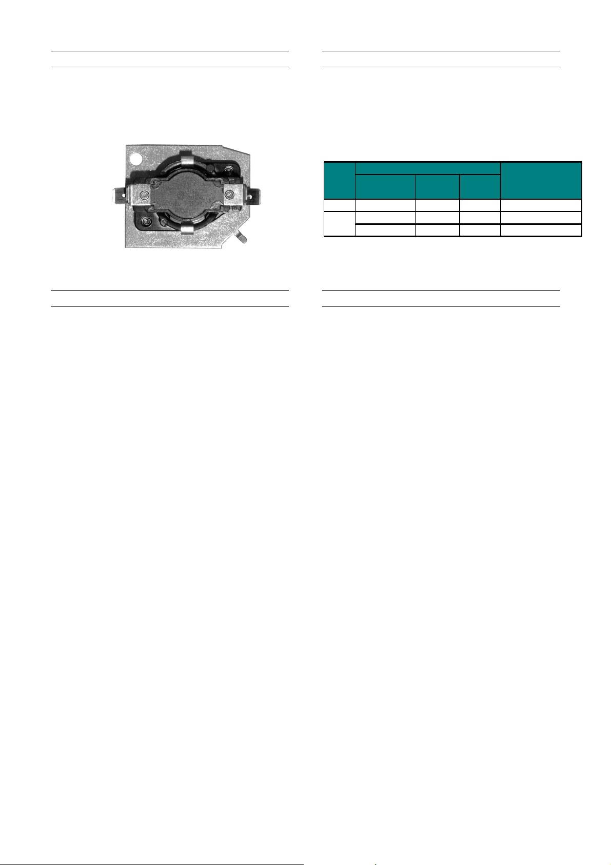
12.11 Fan delay relay
(mm)
(mm)
In case of a not continuous running fan, the fan delay
relay will activate the blower fan motor maximum 60
seconds after the gas valve has opened. The fan will
stop after maximum 120 seconds after th e gas valve has
shut down.
Figure 34 :
12.12 Flue and combustion air piping
Check the complete system at least once a year.
Inspection should include all joints, seams , concentric
adapters and the flue terminal cap. Replace any
defective or heavily corroded parts.
12.13 Air filters
BSHH units have an optional facility for air intake filters.
Standard racks are provided to accommodate 50mm
nominal thickness filter elements. Unless otherwise
specified, filters supplied will be expendable type
synthetic pleated elements. The sizes and quantities
required to suit individual appliances are listed in table
8.
Table 8 : Filter size & quantities schedule
Filter dimensions
Length
Width
Reznor PN
4 496 395 60 61038 395496
4 496 395 60 61038 395496
2 624 496 60 61038 496624
SHH
Qty required
055
083
102
12.14 Condense drain system
Check yearly the condensate disposal system. Remove
the condensate trap and flush it with clean water to
remove any deposit. Check that the piping to the
sanitary drain has not been damaged. Verify that
sanitary drain is not obstructed.
1403BSHH_AMEN,page 25/29
Page 26

y
(
)
)
)
)
(
.
13
TROUBLESHOOTING
General troubleshooting
PROBLEM PROBABLE CAUSE R EMEDY
Venter motor
will not start
Burner will
not light
Burner cycl e
on and off
fan motor will
not run
Fan or venter
motor turns
on and off
while burner
is operating
1. No power to unit. 1. Turn on power, check supply fuses or circuit breaker.
2. No power to venter motor. 2. Check connections at burner rela
3. Integrated burner relay defec tive. 3. Replace burner relay.
4. Defective venter motor. 4. Replace venter motor.
5. Fluse blown
6. Fuse burner relay blown. 6. Replace fuse.
7. LC3 open. 7 a) Reset LC3.
8. Unit in lock-out. 8. Push on reset button.
9.Room thermo stat open. 9.Set thermostat above room temperature.
1. Main valve not operating. 1. a) Check voltage on valve during ignition period.
2. Air in the gas line. 2. Purge gas line.
3. Gas pressure too high or too low. 3. a) Supply pressure should be 20 mbar for natural gas or 37 mbar for
4. No Spark: 4. Check the following :
Loose wire connections. a) Be certain all wire connections are solid.
a
b) Incorrect sp ark gap. b) Maintain spark gap at 3 mm.
c) Spark cable has a short circuit to ground. c) Replace worn or grounded spark cable.
Spark electrode has a short circuit to d) Replace if ceramic spark electrode is cracked or grounded.
d
e) Burner relay not grounded. e) Check burner relay ground wire.
f) Unit not properly grounded. f) Make certain unit is properly field grounded (earthed) and properly
g) Faulty burner relay. g) If voltage is available to the burner relay and all other causes ha ve
5. Combustion air pressure switch 5. First check the following :
not closing upon power to venter. a) Make sure unit is properly vented.
1. Gas pressure too high or too low. 1. Supply pressure should be 15 mbar for natural gas (UK only) or 37
2. Burner relay not grounded. 2. Check burner relay ground wire connection.
3. Faulty burner relay. 3. If (220/240) volts is available to the burner relay and all other causes
4. Flame sensor grounded. 4. Be certain flame sensor lead is not grounded or insulation or ceramic is
5. Cracked ceramic at sensor. 5. Replace sensor.
6. Incorrect polarity. 6. Check polarity and if necessary reverse line voltage wires to terminal
1. Circuit open. 1. Check wiring and connections.
2. Defective fan time delay relay 2. Replace the time delay relay.
3. Defective motor. 3. Replace blower & motor .
1. Motor internal thermal protection device
cycling on and off.
F3.1). 5. Replace fuse.
Replace LC3.
b
c) Check if there is obstruction at the fan side.
b) Check connect or on main gas valve.
c
Check connector on burner relay.
d) Replace valve.
propane gas.
b) Obstruction in the gas line.
c) Gas line connection diameter too small.
phased
been eliminated, replace burner relay.
b) Remove obstructions from vent.
c) Replace faulty tubing to pressure switch.
d) Replace faulty pressure switch.
mbar for propane gas.
have been eliminated, replace burner relay.
not cracked. Replace as required.
block connections.
1. Check motor load against motor rating plate. Replace motor if needed.
and/or venter motor terminals.
L1 to hot lead L2 to neutral).
1210SHH_AMEN,page 26/29
Page 27
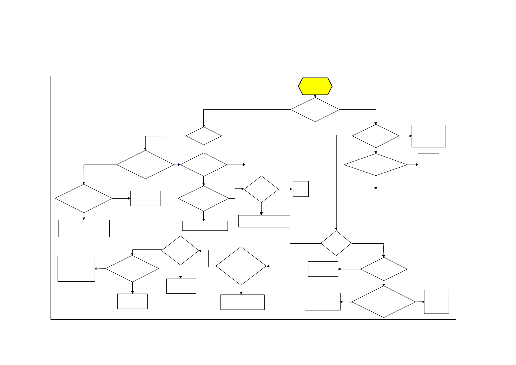
Flowchart
The integrated control relay monitors the operation of the heater. If the heater fails to operate properly, review the flow chart below and see the operating sequence in
section 9.
The general troubleshooting chart on the follo wing pages will also help you to determine the problem.
Trial for
Ignition
Call f o r Heat
Is t he r e
minimum flame current
a t t he con trol
module?
NO
Che ck connec tio ns to flame
sensor and/or moisture in
the burner assembly.
Check gas pressure
and supply voltage.
If ei t her are low,
corre ct and repea t
startup.
YES NO
Is there minimum
flame current at the fla me
sensor?
YES
Re place c ontro l
module.
NO
YES
Is the
igniter position
correct in the gas
flow?
NO
Reposition
spark igniter.
YES NO
Does g a s ig n ite?
Is the flame
sen s or corrode d ?
NO
Is the sensor
located in flame ?
NO
Reposition flam e sensor.
Ai r i n t h e
gas line?
Yes
YES
Bleed a ir from
gas line.
YES
Is burner
jet ope ning
corr e ct s i ze for
gas use d? (chec k
rating label on
heater)
Clean f la me
sensor wit h emery
cloth or steel wool.
Is the
YES
he at e r g rounded
(earthed)?
Connect ground wire (earth)
to unit chassis.
NO
Change injector
(correct si ze shown on
heater rating label)
YES NO
YES
Is there a
spark across gap at
Re place
flame
sensor.
NO
Check wiring and
connectio ns to gas
igniter?
YES
Replace gas
valve.
valve.
Is t he r e
line voltag e at s par k
igniter?
NO
Is there line voltage to
the co ntrol rela y?
NO
Check wir ing
connections
Is gas
flowing ?
YES
NO
line voltage to the gas
Is the re
valve?
NO
YES NO
Is there line
voltage from valve ou tput on
control module to
chass is ?
YES
YES
Check connection
at sp ark igniter.
_______________
Replace igniter
Re place
control
relay
Replace
ignition
control
module.
1403BSHH_AMEN,page 27/29
Page 28

14
SPARE PARTS
GAS SECTION
Description Part number Application
Gas valve single stage burners nat. gas 03 25136 Natural gas
Gas valve single stage burners prop. gas 03 25265 Propane
Gas valve 2 stage burners nat. gas 03 25136 02 Natural gas
Gas valve 2 stage burners prop. g as 03 25136 02 (type 055) Propane
Gas valve 2 stage burners prop. g as 03 35136 P437 (types 083/10 2) Propane
Gas valve modulating burners nat. gas 03 35145 Natural gas
Gas valve modulating burners prop. gas 03 35145 (type 055) Propane
Gas valve modulating burners prop. gas 03 35136 M337 (types 08 3/102) Propane
ELECTRICAL SECTION
Description Part number Application
Control relay 03 25322 All
Spark ignitor 05 25159 All
Flame sensor 05 25140 All
Fan control time delay relay 03 2516 7 All
Limit control LC3 03 24959 01 083/102
Limit control LC3 03 24959 02 055
Pressure switch 30 60618 420 055/102
Pressure switch 30 60617 300 083
Reset switch/burner fail lamp 60 61988 All
Suppresser filter 30 61747 All
Combustion fan motor 20 25745 01 All
Main wiring assembly 1-stage 06 41660 All
Wiring assembly 2-stage 06 41662 All
Relay 2 stage 30 61736 230V All
AIR HANDLING SECTION
Description Part number Application
Centrifugal blower 02 25749 02 055
Centrifugal blower 02 25749 04 083/102
MISCELLANEOUS
Description Part number Application
Silicon tubing 06 20224 CM All
Differential pressure switch, air flow proving
& or clean filter control
Air filters 60 61038 395496 See table 7
Air filters 60 61038 496624 See table 7
30 60617 All
Always quote model size/type & serial number when ordering spares!
1210SHH_AMEN,page 28/29
Page 29

15
13
USER INSTRUCTIONS
15.1 Operating:
How the air heater works:
Gas is burned by an atmospheric burner which fires into a heat
exchanger. The gas burner is controlled by a double gas valve
via an electronic burner control, which is actuated automatically
via external controls i.e. a room thermostat and/or a time switch.
The burner is ignited by a spark igniter. When the burner fires
and warms the heat exchanger, a time delay relay is activated
and switches on the fan after maximum 60 seconds.
At the end of a heating cycle the burner is switched off, the air
circulation fan will continue to run until 120 seconds after heat
demand. Thereafter the fan will remain off until the next cycle is
initiated.
Safety:
1. Flame failure is detected by the flame sensor which will
immediately result in gas valve shut down.
2. Safety against overheating is assured by a overheat
control. This is a control that locks out and switches off
the burner in the event of gross overheating for any
reason. Manual intervention is necessary to reset this
control device. Resetting of the automatic burner control
may also be required.
3. The location of the air heater should be maintained at
normal atmospheric pressure. Changes to the building
after air heater installation, should have regard to the
heating installation, i.e. structural changes causing
excessive draughts from doors, windows etc. Other air
handlers and installation of air extraction equipment,
which may cause a negative pressure environment, can
seriously affect the operation of this type of air heater,
especially if combustion air supply is not ducted.
15.2 To light the heater
1. Switch on the electricity supply to the air heater.
2. Turn on the gas supply to the air heater.
3. Ensure time switch (if fitted) is set to a 'ON' cycle.
4. Adjust control/room thermostat to desired temperature.
5. Air heater will light automatically when the room
thermostat calls for heat.
6. If the appliance does not light:
a) check if the burner control does not require resetting.
An indicator light glows at the front panel of the
appliance and on a remote control (if fitted). Reset by
pushing light/button on appliance or the remote control.
b) check if thermal overheat control requires resetting
7. If the thermal overheat control requires resetting and
doing so restarts the air heater, wait until the appliance
warms to thermal equilibrium, to ensure the overheat
control does not lock out again. If it does and the
temperature near the heater is less than 30°C , then
switch off the appliance and call for service. If the
temperature is over 30°C, take appropriate action to
reduce the ambient temperature near the air heater.
15.3 Air circulation:
1. The space heating process is for air to be circulated
through the appliance whereby it gains heat from a heat
exchanger. The air is directly discharged into the space
to be heated. The air is eventually recirculated.
Therefore it is very important that an unobstructed path
for the circulation of the air will be maintained. This is
particularly important if the air heater has been installed
to blow through the wall between two rooms.
2. Sometimes the air circulation fan of the appliance is
connected to a remote over-ride switch. This enables
cool air to be used for circulation purposes when the air
heater is not used for heating purposes e.g. in summer.
To use this feature:
a) switch ON electricity
b) switch ON manual override switch, this may be fitted
as a feature on a remote composite control.
15.4 Maintenance
1. Maintenance and service must only be carried out by
appropriately qualified persons e.g. "Corgi" registered
undertakings.
2. It is in your interest to ensure proper service and
maintenance is carried out at a regular basis. Periods
between service are dependent upon the local
environment where the heater is installed. All gas
appliances should be serviced at least once a year.
3. In case of any damage to the appliance, it must be shut
down completely and checked by an appropriately
qualified person.
4. In the event of difficulties in resolving any of these
matters, please do not hesitate to contact AmbiRad or
their official distributor.
Subject to modifications
1403BSHH_AMEN,page 29/29
 Loading...