


Rsi S Series
Rsi S Series
Low Voltage
Low Voltage
Variable Frequency Drive
Variable Frequency Drive
Instruction Manual
Instruction Manual
890049-00-00
2016 Benshaw Corporation
©
Benshaw retains the right to change specifications and illustrations in text without prior notification.
The contents of this document may not be copied without the explicit permission of Benshaw.


iii
Safety Information
Safety Information
Read and follow all safety instructions in this manual precisely to avoid unsafe operating conditions,
property damage, personal injury, or death.
Safety symbols in this manual
Indicates an imminently hazardous situation which, if not avoided,
will result in severe inj
ury or death
.
Indicates a potentially
hazardous situation which, if not avoided, could result in injury or death.
Indicates a potentially hazardous situation that, if not avoided, could result in
minor injury or
property
damage.
Safety information
•
Do not open the cover of the equipment while it is on or operating. Likewise, do not operate the
inverter while the cover is open
. Exposure of high voltage terminals or charging area to the
external environment may result in an electric shock. Do not remove any covers or touch the
internal circuit boards (PCBs) or electrical contacts on the product when the power is on or
during operation. Doing so may result in serious injury, death, or serious property damage.
•
Do not open the cover of the equipment even when the power supply to the inverter has
been turned off unless it is necessary for maintenance or regular inspection. Opening the
cover may result in an electric shock even when the power supply is off
.
•
The equipment may hold charge long after the power supply has been turned off. Use a multimeter to make sure that there is no voltage before working on the inverter, motor or motor cable.
•
This equipment must be grounded for safe and proper operation.
•
Do not supply power to a faulty inverter. If you find that the inverter is faulty, disconnect the
power supply and have the inverter professionally repaired.
•
The inverter becomes hot during operation. Avoid touching the inverter until it has cooled to
avoid burns
.
•
Do not allow foreign objects, such as screws, metal chips, debris, water, o
r oil to get inside the

Quick Reference Table
iv
inverter.
Allowing foreign objects inside the inverter m
ay cause the inverter to malfunction or
result in a fire
.
•
Do not operate the inverter with wet hands. Doing so may result in electric shock.
•
Check the information about the protection level for the circuits and devices.
The following connection terminals and devices are the Electrical Protection level 0 per IEC -
61140. This means that the circuit protection level depends on the basic insulation. If there is no
basic insulation this may cause electric shock. When installing or wiring the connection terminals
and devices, take the same protective action as with the power wire.
- Multi-function Input: P1-P5, CM
- Analog Frequency Input: VR, V1, I2, TI
- Safety Function: SA, SB, SC
- Analog Output: AO, TO
- Contact: Q1, EG, 24, A1, B1, C1, S+, S-, SG
- Fan
•
The protection level of this equipment (inverter) is the Electrical Protection level I.
•
Do not modify the interior workings of the inverter.
Doing so
will void the warranty.
•
The inverter is designed for 3-phase motor operation. Do not use the inverter to operate a single
phase motor.
•
Do not place heavy objects on top of electric cables. Doing so may damage the cable and
result in an electric shock.
Note
–
Short Ci
rcuit Current Rating, SCCR
Maximum allowed prospective short-circuit current at the input power connection is defined in IEC
60439-1 as 100 kA. Depending on the selected MCCB, the “S” Series inverter is suitable for use in
circuits capable of delivering a maximum of 100 kA RMS symmetrical amperes when protected by a
100 kaic rated breaker or fuses.

v
Safety Information
Quick Reference Table
The following table contains situations frequently encountered while working with inverters. Refer
to the situations in the table to quickly and easily locate answers to your questions.
Situation Reference
I want to run a slightly higher rated motor than the inverter’s rated capacity.
p.348
I want to configure the inverter to start operating as soon as the power source i
s
applied.
p. 81
I want to configure the motor’s parameters.
p.143
I want to set up sensorless vector control.
p.146
Something seems to be wrong with the inverter or the motor.
p.336
What is auto tuning? p.143
What are the recommended wiring lengths? p. 24
The motor is too noisy. p. 176
I want to apply PID control on my system. p. 135
What are the factory default settingss for P1–P5 multi-function terminals?
p. 27
I want to view all of the parameters I have modified. p. 186
I want to review recent fault and warning histories. p. 302
I want to change the inverter’s operating frequency using a potentiometer. p. 52
I want to install a frequency meter using an analog terminal. p. 29
I want to display the supply current to motor. p. 55
I want to operate the inverter using a multi-step speed configuration. p. 75
The motor runs too hot. p. 213
The inverter is too hot. p. 5
I want to change the items that are monitored on the keypad. p. 207


Table of Contents
vii
Contents
1 Preparing the Installation ...................................................................................... 1
Product Identification .......................................................................................... 1
Part Names ........................................................................................................... 2
Installation Considerations .................................................................................. 4
Selecting and Preparing a Site for Installation ................................................... 5
Cable Selection ..................................................................................................... 9
2 Installing the Inverter .......................................................................................... 11
Mounting the Inverter ........................................................................................ 13
Cable Wiring ....................................................................................................... 17
Post-Installation Checklist ................................................................................. 35
Test Run .............................................................................................................. 37
3 Learning to Perform Basic Operations ............................................................. 39
About the Keypad .............................................................................................. 39
Learning to Use the Keypad .............................................................................. 43
Application Examples ........................................................................................ 47
Monitoring the Operation ................................................................................. 55
4 Learning Basic Features ....................................................................................... 59
Setting Frequency Reference ............................................................................ 62
Frequency Hold by Analog Input ....................................................................... 74
Changing the Displayed Units (Hz↔Rpm) ....................................................... 74
Setting Multi-step Frequency............................................................................ 75
Command Source Configuration ...................................................................... 77
Local/Remote Mode Switching ......................................................................... 79
Forward or Reverse Run Prevention ................................................................. 81
Power-on Run ..................................................................................................... 81
Reset and Restart ............................................................................................... 82
Setting Acceleration and Deceleration Times .................................................. 84
Acc/Dec Pattern Configuration ......................................................................... 88

Table of Contents
viii
Stopping the Acc/Dec Operation ...................................................................... 91
V/F(Voltage/Frequency) Control ....................................................................... 91
Torque Boost ......................................................................................................94
Output Voltage Setting ...................................................................................... 95
Start Mode Setting ........................................................................................... 96
Stop Mode Setting ............................................................................................. 97
Frequency Limit ............................................................................................... 100
2nd Operation Mode Setting ............................................................................ 102
Multi-function Input Terminal Control ............................................................ 103
P2P Setting ....................................................................................................... 105
Multi-keypad Setting ....................................................................................... 107
User Sequence Setting .................................................................................... 108
Fire Mode Operation ........................................................................................ 117
5 Learning Advanced Features ............................................................................ 119
Operating with Auxiliary References .............................................................. 120
Jog operation.................................................................................................... 125
Up-down Operation ......................................................................................... 128
3-Wire Operation.............................................................................................. 129
Safe Operation Mode ...................................................................................... 130
Dwell Operation ............................................................................................... 132
Slip Compensation Operation ......................................................................... 133
PID Control ....................................................................................................... 135
Auto Tuning ...................................................................................................... 143
Sensorless Vector Control for Induction Motors ............................................ 146
Sensorless Vector Control for PM (Permanent-Magnet) Synchronous Motors
154
Kinetic Energy Buffering (KEB) Operation ..................................................... 165
Torque Control ................................................................................................. 168
Energy Saving Operation ................................................................................. 171
Speed Search Operation .................................................................................. 172
Auto Restart Settings ....................................................................................... 176
Table of Contents
ix
Operational Noise Settings (carrier frequency settings) ............................... 178
2nd Motor Operation ....................................................................................... 179
Supply Power Transition .................................................................................. 181
Cooling Fan Control ......................................................................................... 182
Input Power Frequency and Voltage Settings ................................................ 182
Read, Write, and Save Parameters ................................................................. 183
Parameter Initialization ................................................................................... 183
Parameter View Lock ....................................................................................... 184
Parameter Lock ................................................................................................ 185
Changed Parameter Display ........................................................................... 186
User Group ........................................................................................................ 186
Easy Start On .................................................................................................... 188
Config(CNF) Mode ........................................................................................... 189
Timer Settings .................................................................................................. 190
Brake Control .................................................................................................... 191
Multi-Function Output On/Off Control ........................................................... 192
Press Regeneration Prevention ....................................................................... 193
Analog Output .................................................................................................. 195
Digital Output ................................................................................................... 200
Keypad Language Settings ............................................................................. 207
Operation State Monitor ................................................................................. 207
Operation Time Monitor .................................................................................. 210
6 Learning Protection Features ........................................................................... 213
Motor Protection ............................................................................................. 213
Inverter and Sequence Protection .................................................................. 220
Under load Fault Trip and Warning ................................................................. 223
Fault/Warning List ............................................................................................ 229
7 RS-485 Communication Features .................................................................... 231
Communication Standards ............................................................................. 231
Communication System Configuration .......................................................... 232

Table of Contents
x
Communication Protocol ................................................................................ 239
Compatible Common Area Parameter ........................................................... 241
Expansion Common Area Parameter ............................................................. 245
8 Table of Functions .............................................................................................. 255
Operation Group .............................................................................................. 255
Drive group (PAR→dr) ..................................................................................... 257
Basic Function group (PAR→bA) ....................................................................262
Expanded Function group (PAR→Ad) ........................................................... 268
Control Function group (PAR→Cn)................................................................. 273
Input Terminal Block Function group (PAR→In) ........................................... 280
Output Terminal Block Function group (PAR→OU) ...................................... 285
Communication Function group (PAR→CM) ............................................... 290
Application Function group (PAR→AP) ......................................................... 295
Protection Function group (PAR→Pr) ........................................................... 298
2nd Motor Function group (PAR→M2) .......................................................... 303
User Sequence group (US) .............................................................................. 305
User Sequence Function group(UF) ................................................................ 308
Groups for LCD Keypad Only .......................................................................... 329
9 Troubleshooting .................................................................................................. 333
Trips and Warnings ........................................................................................... 333
Troubleshooting Faults .................................................................................... 336
Troubleshooting Other Faults ......................................................................... 339
10 Maintenance ......................................................................................................... 345
Regular Inspection Lists ................................................................................... 345
Storage and Disposal ....................................................................................... 348
11 Technical Specification ....................................................................................... 351
Drive Ratings .................................................................................................... 351
Product Specification Details .......................................................................... 355
External Dimensions (IP 20 Type) .................................................................... 358

Table of Contents
xi
Fuse and Reactor Specifications ..................................................................... 363
Terminal Screw Specification .......................................................................... 364
Braking Resistor Specification ......................................................................... 365
Continuous Rated Current Derating ............................................................... 366
Heat Emmission ............................................................................................... 368
12 Applying Drives to Single-Phase Input Application .................................... 370
Introduction ...................................................................................................... 370
Power(HP), Input Current and Output Current............................................... 371
Input Frequency and Voltage Tolerance ......................................................... 371
Product Warranty ....................................................................................................... 372
UL mark ........................................................................................................................ 373
Manual Revision History ........................................................................................... 374

Preparing the Installation
0

Preparing the Installation
1
1 Preparing the Installation
This chapter provides details on product identification, part names, correct installation and cable
specifications. To install the inverter correctly and safely, carefully read and follow the instructions.
Product Identification
Product name and specifications are detailed on the nameplate (label). The illustration below
shows the nameplate. Check the nameplate before installing the product and make sure that the
product meets your requirements. For more detailed product specifications, refer to 11.1 Drive
Ratings.
N
ote
Check the product name
, open the packaging
, and
then
confirm
that the product is
free from
defect
s.
Contact your supplier if you have any issues or questions about your product.
Output
Specifications
RSI – 003 – SS – 4 – C
RSI – Benshaw Redi Start Inverter
003 – HP
001 – 1 HP
002 – 2 HP
003 – 3 HP
005 – 5 HP
007 – 7.5 HP
010 – 10 HP
SS – Benshaw “S” Series
4 – Voltage Class: 2 – 240V
4 – 480V
C – Open Chassis
(Nema/UL Open
type, IP
-00)
RSI-003-SS-4C
Input: 380 – 480V 3 Phase 50/60Hz.
HD: 5.9A ND: 7.5A
Output: 0-Input V 3 Phase 0.01 – 400 Hz.
HD: 5.5A ND: 6.9A
4.2 kVA
Ser. No.:
Inspected By:
Model Number
Power
Source

Preparing the Installation
2
Part Names
The illustration below displays part names. Details may vary between product groups.
Three Phase 230V / 460V
0.5 HP~5 HP (0.4~3.7kW )
Cooling fan
Cooling fan cover
Top cover
Inverter body
Keypad
Control terminal block
Front cover (L)
Front cover (R)
(Option)

Preparing the Installation
3
Three Phase 230V / 460V
7.5 HP~ 10 HP (5.5
––––
7.5kW)
Cooling fan cover
Top cover
Inverter body
Control terminal cover
Front cover
Cable guide
Control terminal
block
Keypad
Cooling fan
Preparing the Installation
4
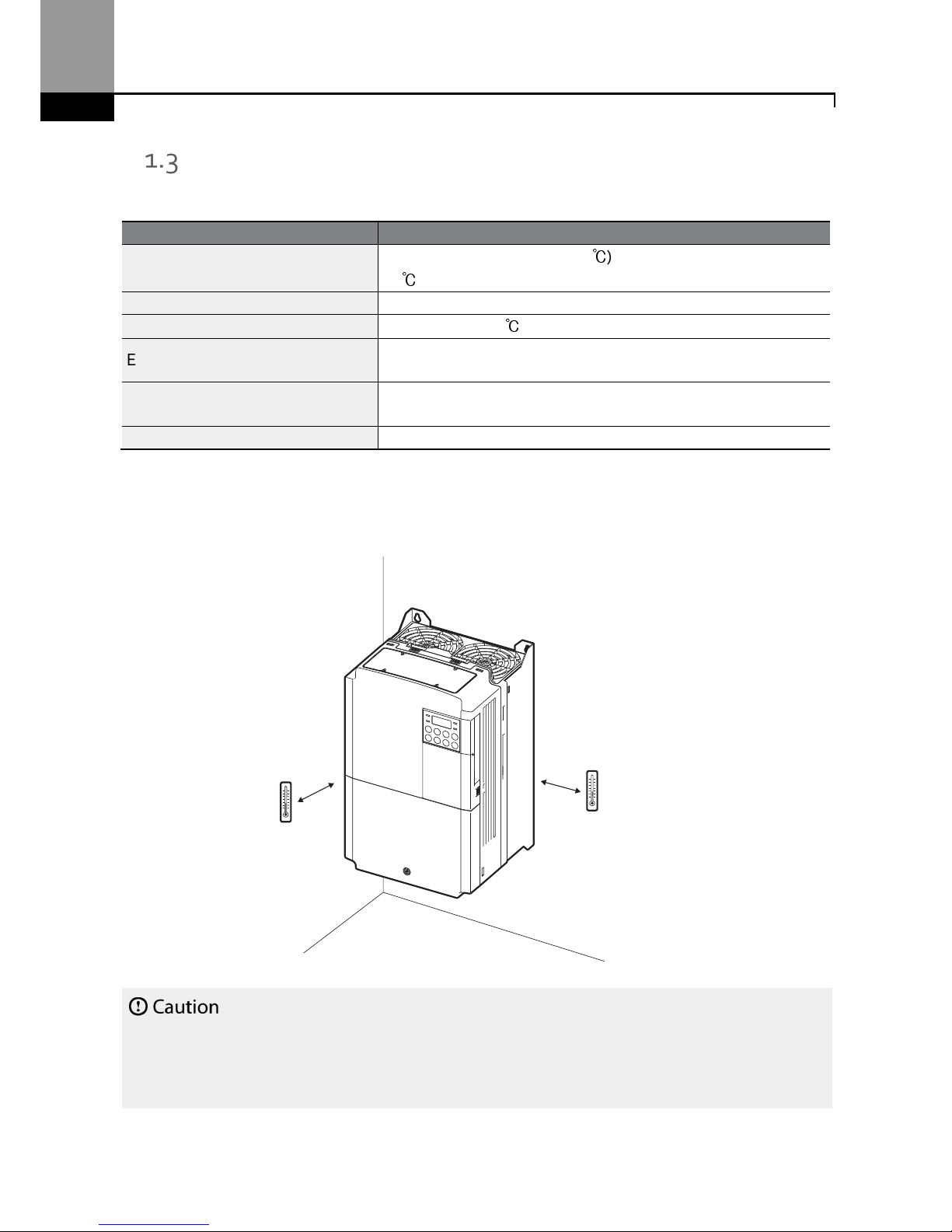
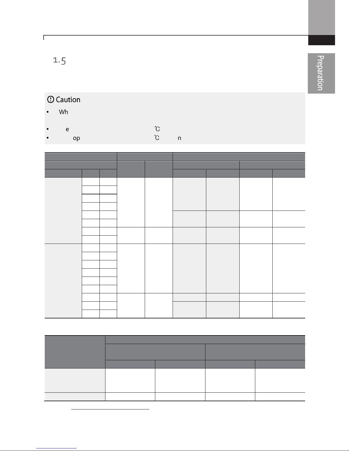
Installation Considerations
The environment can significantly impact the lifespan and reliability of the product. The table below
details the ideal operation and installation conditions for the inverter.
Items
Description
Ambient Temperature*
Heavy Duty: 14–104°F (-10–40℃) Normal Duty: 14–122°F (-10–
50℃)
Ambient Humidity
90% relative humidity (no condensation
)
Storage Temperature
- 4–149°F (-20–65℃)
Environmental Factors
An environment free
from
corrosive or
flammable gas
es
, oil
residue or dust
Altitude/Vibration
L
ower than
3,280 ft
(1,000 m)
above
sea level/
less than
1G
(9.8m/sec2)
Air Pressur
e 20.7
– 31.3 inHg
(10 –
15 PSI,
70 –
106kPa
)
* The ambient temperature is the temperature measured at a point 2” (5 cm) from the surface of
the inverter.
Do not allow the ambient temperature to exceed the allow
able range
while operating
the inverter.
See side by s
ide installation
on pages 7 and 8.
2”
2”

Preparing the Installation
5
Selecting and Preparing a Site for Installation
When selecting an installation location consider the following points:
•
The inverter must be installed on a wall that can support the inverter’s weight.
•
The location must be free from vibration. Vibration can adversely affect the long term
operation of the inverter.
•
The inverter can become very hot during operation. Install the inverter on a surface that is fireresistant or flame-retardant and with sufficient clearance around the inverter to allow air to
circulate. The illustrations below detail the required installation clearances.
See side by side installation on pages 7 and 8.
2” minimum
2” minimum
2” minimum
4” minimum
4” minimum

Preparing the Installation
6
•
Ensure sufficient air circulation is provided around the inverter when it is installed. If the
inverter is to be installed inside a panel, enclosure, or cabinet rack, carefully consider the
position of the inverter’s cooling fan and the ventilation louver. The cooling fan must be
positioned to efficiently transfer the heat generated by the operation of the inverter.
See side by side installation on pages 7 and 8.
Preparing the Installation
7
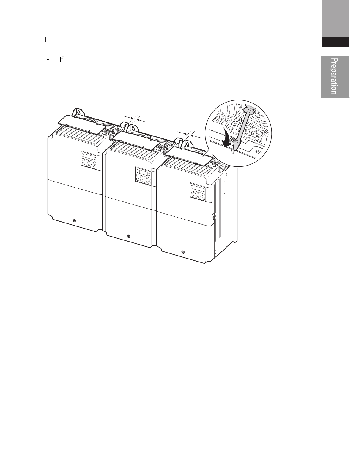
•
If you are installing multiple inverters in one location, arrange them side-by-side and remove
the top covers. The top covers MUST be removed for side-by-side installations. Use a flat
head screwdriver to remove the top covers.
0.1”
0.1”
Preparing the Installation
8
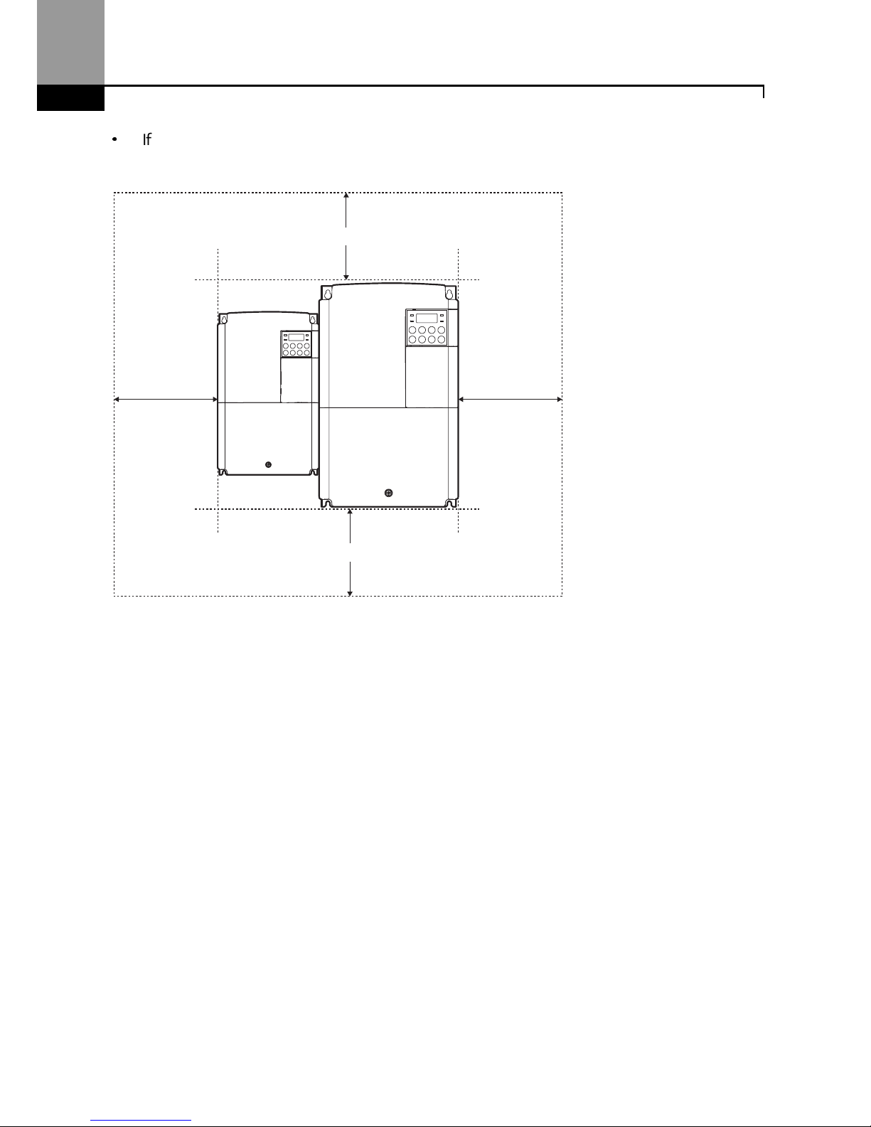
•
If you are installing multiple inverters, of different ratings, provide sufficient clearance to meet
the clearance specifications of the larger inverter.
2” minimum
2” minimum
4” minimum
4” minimum
Preparing the Installation
9
Cable Selection
When you install power and signal cables in the terminal blocks, only use cables that meet the
required specification for the safe and reliable operation of the product. Refer to the following
information to assist you with cable selection.
•
Wherever possible use cables with the largest cross-sectional area for main power wiring to
ensure that voltage drop does not exceed 2%.
•
Use copper cables rated for 600V, 75℃ for power terminal wiring.
•
Use copper cables rated for 300V, 75℃ for control terminal wiring.
Ground Cable and Power Cable Specifications
Load
Ground
Power I/O
mm2 AWG
mm2
AWG
HP kW
R/S/T
U/V/W
R/S/T
U/V/W
3–Phase
200V
0.5 0.4
4 12
2 2 14 14
1 0.75
2 1.5
3 2.2
5 3.7
3.5 3.5 12 12
5.4 4
7.5 5.5
5.5 10 6 6 10 10
10 7.5
3–Phase
400V
0.5 0.4
4 12 2 2 14 14
1 0.75
2 1.5
3 2.2
5 3.7
7.5 5.5
4 12
2.5 2.5 14 14
10 7.5
4 4 12 12
Signal (Control) Cable Specifications
Terminals
Signal Cable
Without
Crimp Terminal Connectors
(Bare wire)
With
Crimp
Terminal
Connectors
(Bootlace Ferrule)
mm2
AWG
mm2
AWG
P1~P
5*/CM/VR/V1/I2
/AO/Q1/EG/24/TI/TO*
/SA,SB,SC/S+,S-,SG
0.75 18 0.5 20
A1/B1/C1
1.0 17 1.5 15
* Refer to Step 4 Control Terminal Wiring.

Preparing the Installation
10
11
Installing the Inverter
2 Installing the Inverter
This chapter describes the physical and electrical installation methods, including mounting and
wiring of the product. Refer to the flowchart and basic configuration diagram provided below to
understand the procedures and installation methods to be followed to install the product
correctly.
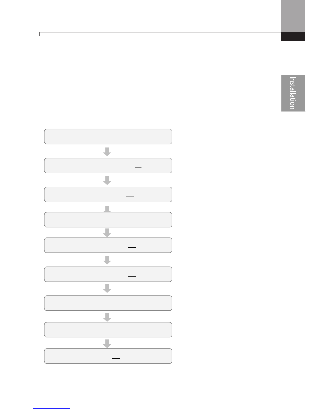
Installation Flowchart
The flowchart lists the sequence to be followed during installation. The steps cover equipment
installation and testing of the product. More information on each step is referenced in the steps.
*
Product Identification (p.1)
Select the Installation Location (p.4)
Mounting the Inverter (p.13)
Wiring the Ground Connection (p.21)
Power and Signal Wiring (p.22)
Post-Installation Checks (p.35)
Turning on the Inverter
Parameter Configuration (p.47)
Testing (p.37)
Installing the Inverter
12
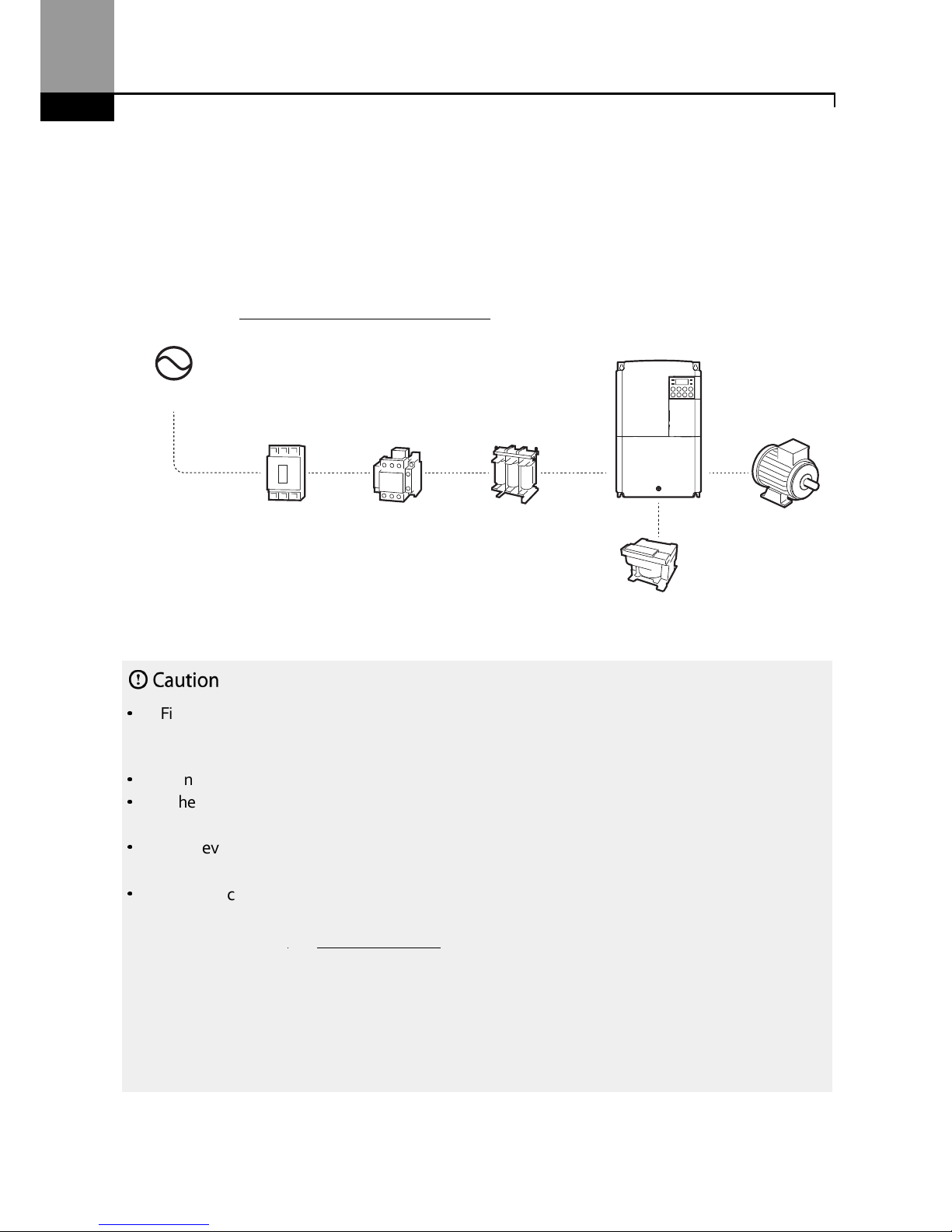
Basic Configuration Diagram
The reference diagram below shows a typical system configuration showing the inverter and
peripheral devices.
Prior to installing the inverter, ensure that the product is suitable for the application (power rating,
capacity, etc). Ensure that all of the required peripheral devices (breakers, contactors, etc.) and
optional devices (filters, brake resistors, etc.) are sized correctly. For more details on peripheral
devices, refer to 11.4 Fuse and Reactor Specifications.
•
Figures in this manual are shown with covers or circuit breakers removed to show a more detailed
view of the installation arrangements. Install covers and circuit breakers before operating the
inverter. Operate the product according to the instructions in this manual.
•
Do not start or stop the inverter using a magnetic contactor installed on the input power supply.
•
If the inverter is damaged and loses control, the machine may cause a dangerous situation. Install
an additional safety device such as an emergency brake to prevent these situations.
•
High levels of current draw during power-on can affect the system. Ensure that correctly
rated circuit breakers are installed to operate safely during power-on situations.
•
Reactors can be installed to improve the power factor. Note that reactors may be installed
within 30 ft (9.14 m) from the power source if the input power exceeds 10 times 0f inverter
capacity. Refer to 11.4 Fuse and Reactor Specification and carefully select a reactor that
meets
the requirements.
Power source
Circuit
breaker
Input side
Magnetic
contactor
(Optional)
AC reactor
DC reactor
Output side
Motor
(Optional)
(Optional)
13
Installing the Inverter
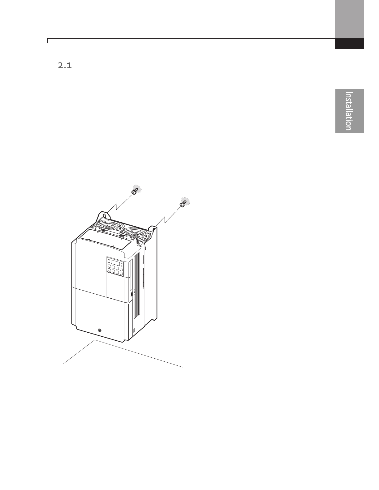
Mounting the Inverter
Mount the inverter on a wall or inside a panel following the procedures provided below. Before
installation, ensure that there is sufficient space to meet the clearance specifications, and that
there are no obstacles impeding the cooling fan’s air flow.
Select a wall or panel suitable to support the installation. Refer to 11.3 External Dimensions and
check the inverter’s mounting bracket dimensions.
1 Use a level to draw a horizontal line on the mounting surface, and then carefully mark the
mounting points.
2 Drill the two upper mounting bolt holes, and then install the mounting bolts. Do not fully
tighten the bolts at this time. Fully tighten the mounting bolts after the inverter has been
mounted.

Installing the Inverter
14
3 Mount the inverter on the wall or inside a panel using the two upper bolts, and then fully
tighten the mounting bolts. Ensure that the inverter is placed flat on the mounting surface,
and that the installation surface can securely support the weight of the inverter.

15
Installing the Inverter
•
Do not transport the inverter by lifting with the inverter’s covers or plastic surfaces. The inverter
may tip over if covers break, causing injuries or damage to the product. Always support the
inverter using the metal frames when moving it.
•
Hi-capacity inverters are very heavy and bulky. Use an appropriate transport method that is
suitable for the weight.
Note
The quantity and dimensions of the mounting brackets
vary based on frame size. Refer to
0
External Dimensions for detailed information about your model.
Inverters with small frames (0.4–0.8kW) have only two mounting brackets. Inverters with large
frames have 4 mounting brackets.

Installing the Inverter
16
•
Do not install the inverter on the floor or mount it sideways against a wall.
The inverter MUST be
installed vertically, on a wall or inside a panel, with its rear flat on the mounting surface.

17
Installing the Inverter
Cable Wiring
Open the front cover, remove the cable guides and control terminal cover, and then install the
ground connection as specified. Complete the cable connections by connecting an appropriately
rated cable to the terminals on the power and control terminal blocks.
Read the following information carefully before carrying out wiring connections to the inverter. All
warning instructions must be followed.
•
Install the inverter before carrying out wiring connections.
•
Ensure that no small metal debris, such as wire cut-offs, remain inside the inverter. Metal debris in
the inverter may cause inverter failure.
•
Tighten terminal screws to their specified torque. Loose terminal block screws may allow the
cables to disconnect and cause short circuit or inverter failure. Refer to 11.5 Terminal Screw S for
torque specifications.
•
Do not place heavy objects on top of electric cables. Heavy objects may damage the cable and
result in electric shock.
•
The power supply system for this equipment (inverter) is a grounded system.
Only use a grounded
power supply system for this equipment (inverter). Do not use a TT, TN, IT, or corner grounded
system with the inverter.
•
The equipment may generate direct current in the protective ground wire. When installing the
residual current device (RCD) or residual current monitoring (RCM), only Type B RCDs and RCMs
can be used.
•
Use cables with the largest cross-sectional area, appropriate for power terminal wiring, to ensure
that voltage drop does not exceed 2%.
•
Use copper cables rated at 600V, 75℃ for power terminal wiring.
•
Use copper cables rated at 300V, 75℃ for control terminal wiring.
•
Separate control circuit wires from the main circuits and other high voltage circuits.
•
Check for short circuits or wiring failure in the control circuit. They could cause system failure or
device malfunction.
•
Use shielded cables when wiring the control circuit.
Failure to do so may cause malfunction due to
interference. If a ground is needed, use STP (Shielded Twisted Pair) cables.
•
If you need to re-wire the terminals due to wiring-related faults, ensure that the inverter keypad
display is turned off and the charge lamp under the front cover is off before working on wiring
connections. The inverter may hold a high voltage electric charge long after the power supply has
been turned off.

Installing the Inverter
18
Step 1 Front Cover, Control Terminal Cover and Cable Guide
The front cover, control terminal cover and cable guide must be removed to install cables. Refer to
the following procedures to remove the covers and cable guide. The steps to remove these parts
may vary depending on the inverter model.
0.5HP~3HP (0.4
––––
2.2kW) 3-phase
1 Loosen the bolt that secures the front cover (right side). Push and hold the latch on the right
side of the cover. Then remove the cover by lifting it from the bottom and moving it away from
the front of the inverter.
2 Remove the bolt that secures the front cover (left side) (❶). Push and hold the latch on the left
side of the cover. Then remove the cover by lifting it from the bottom and moving it away from
the front of the inverter (❷).

19
Installing the Inverter
3 Connect the cables to the power terminals and the control terminals. For cable specifications,
refer to 1.5 Cable Selection.
5HP~10HP (3.7
––––
7.5kW) 3-phase
1 Loosen the bolt that secures the front cover. Then remove the cover by lifting it from the
bottom and away from the front.
Installing the Inverter
20
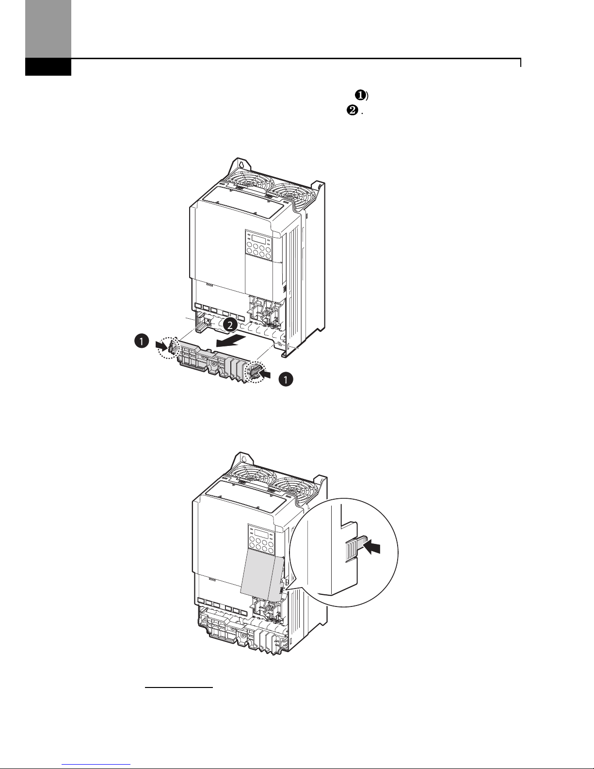
2 Push and hold the levers on both sides of the cable guide (❶) and then remove the cable guide
by pulling it directly away from the front of the inverter (❷). In some models where the cable
guide is secured by a bolt, remove the bolt first.
3 Push and hold the tab on the right side of the control terminal cover. Then remove the cover by
lifting it from the bottom and moving it away from the front of the inverter.
4 Connect the cables to the power terminals and the control terminals. For cable specifications,
refer to 1.5 Cable Selection.
21
Installing the Inverter
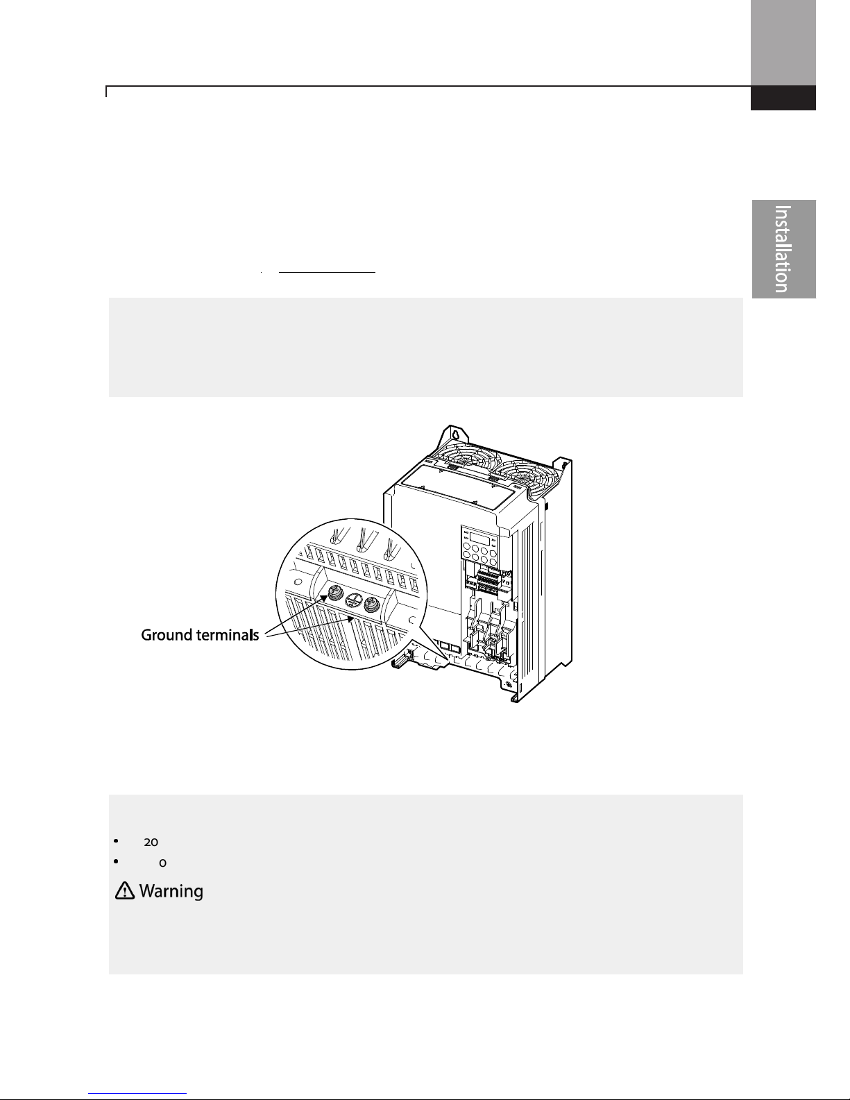
Step 2 Ground Connection
Remove the front cover(s), cable guide, and the control terminal cover. Then follow the
instructions below to install the ground connection for the inverter.
1 Locate the ground terminal and connect an appropriately rated ground cable to the
terminals. Refer to 1.5 Cable Selection to find the appropriate cable specification for your
installation.
2 Connect the other ends of the ground cables to the supply earth (ground) terminal.
Note
•
200 V products require Class 3 grounding. Resistance to ground must be < 100Ω.
•
400 V products require Special Class 3 grounding. Resistance to ground must be < 10Ω.
Install g
round
connections for
the inverter and the motor
by following the correct
specifications to
ensure safe and accurate operation. Using the inverter and the motor without the specified grounding
connections may result in electric shock.
Note
To connect an LCD
keypad, remove the plastic knock
-
out from the bottom of the
front cover
(right
side) or from the control terminal cover. Then connect the signal cable to the RJ-45 port on the control
board.

Installing the Inverter
22
Step 3 Power Terminal Wiring
The following illustration shows the terminal layout on the power terminal block. Refer to the
detailed descriptions to understand the function and location of each terminal before making
wiring connections. Ensure that the cables selected meet or exceed the specifications in 1.5 Cable
Selection before installing them.
•
Apply rated torques to the terminal screws. Loose screws may cause short circuits and
malfunctions. Tightening the screw too much may damage the terminals and cause short circuits
and malfuctions.
•
Use copper wires only with 600V, 75℃ rating for the power terminal wiring, and 300V, 75℃rating
for the control terminal wiring.
•
Do not connect two wires to one terminal when wiring the power.
•
Power supply wiring must be connected to the R, S, and T terminals. Connecting them to the
output
(U, V, W terminals) will cause damage to the inverter. Arrangement of the input phase sequence is
not critical.
•
Motor must be connected to the U, V, and W Terminals.
23
Installing the Inverter
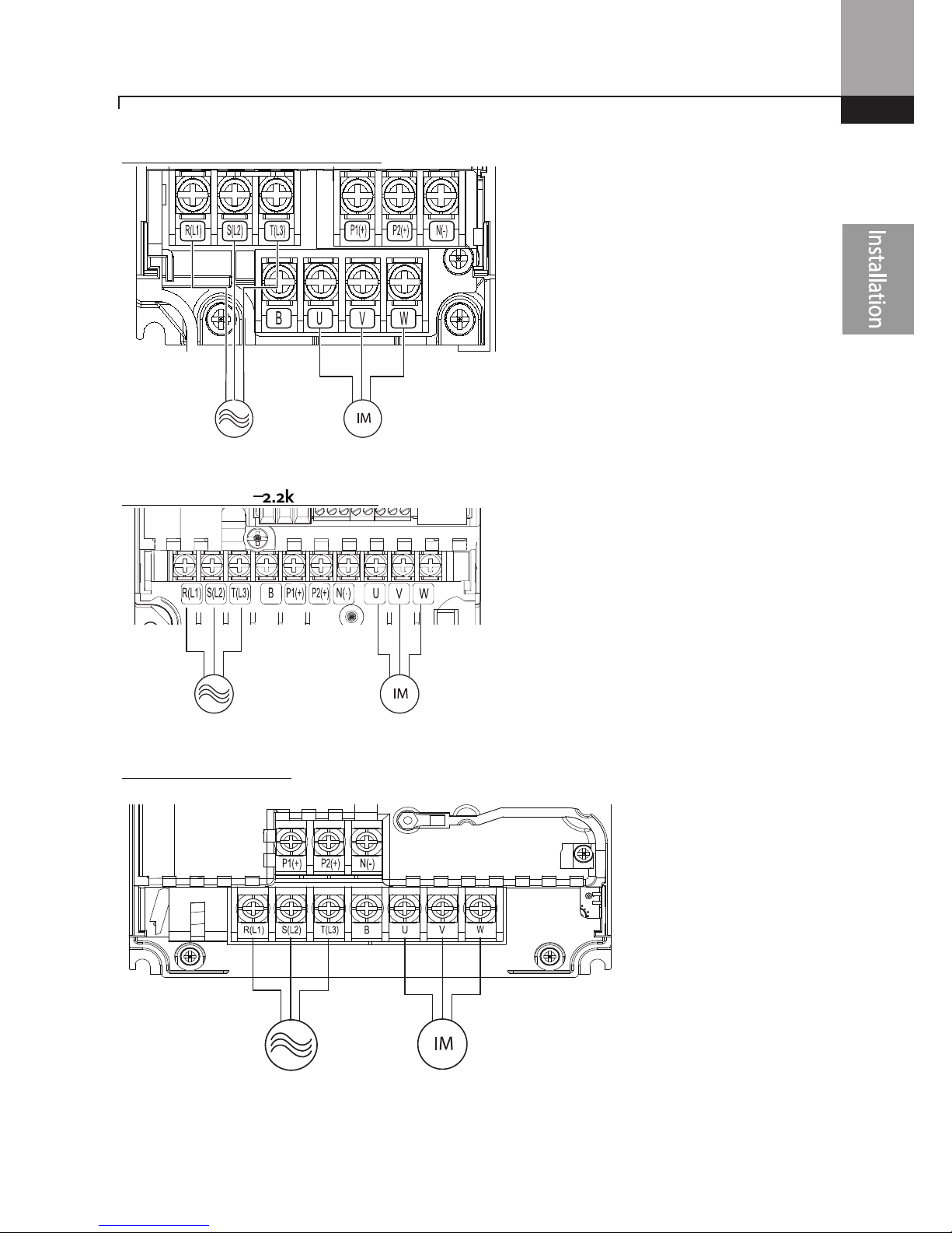
0.5HP~1.0HP (0.4~0.8kW) 3-phase
2.0HP~3.0HP (1.5
––––
2.2kW) 3-phase
5.0HP (3.7kW) 3-phase
3-phase AC Input Motor
3-phase AC Input Motor
3-phase AC Input
Motor
Installing the Inverter
24
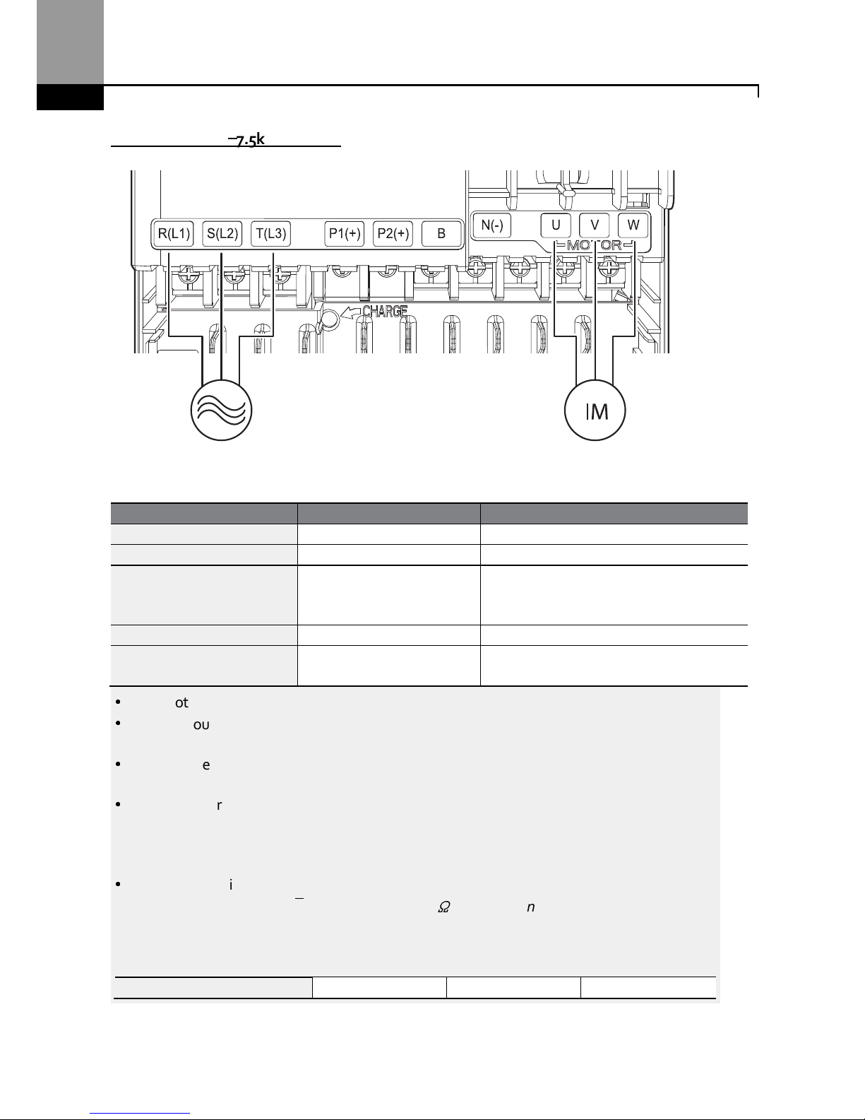
7.5HP~ 10HP (5.5
––––
7.5kW) 3-phase
Power Terminal Labels and Descriptions
Terminal Labels
Name
Description
R(L1)/S(L2)/T(L3)
AC power input terminal
Main supply AC power connections.
P2(+
)/N(-) DC link termi
nal DC voltage terminals.
P1(+)/P2(+) DC reactor terminal
DC reactor wiring connection.
(When you
use the DC reactor, must remove shortbar)
P2(+)/B Brake resistor terminals
Brake resistor wiring conne
ction
.
U/V/W Motor output terminals
3-phase ind
uction motor wiring
connections.
•
Do not use 3 core cables to connect a remotely located motor to the inverter
.
•
When you operating Brake resistor, the motor may vibrate under the Flux braking
operation. In this case, turn off the Flux braking(Pr.50).
•
Make sure that the total cable length does not exceed 665ft (202m). For inverters < =
4.0kW capacity, ensure that the total cable length does not exceed 165ft (50m).
•
Long cable runs can cause reduced motor torque in low frequency applications due to
voltage drop. Long cable runs also increase a circuit’s susceptibility to stray capacitance and
may trigger over-current protection devices or result in malfunction of equipment
connected to the inverter.
•
Voltage drop is calculated by using the following formula:
Voltage Drop (V) = [√3 X cable resistance (mΩ/m) X cable length (m) X current(A)] / 1000
Use cables with the largest possible cross-sectional area to ensure that voltage drop is
minimized over long cable runs. Lowering the carrier frequency and installing a micro surge
filter may also help to reduce voltage drop.
Allowed Carrier Frequency
<
15 kHz
<
5 kHz
<
2.5 kHz
3-phase AC input Motor
25
Installing the Inverter
Do not connect power to the inverter until installati
on has been
fully
completed and the inverter is
ready to be operated. Doing so may result in electric shock.
•
Power supply cables must be connected to the R, S, and T terminals. Connecting power cables to
other terminals will damage the inverter.
•
Use insulated ring lugs when connecting cables to R/S/T and U/V/W terminals.
•
The inverter’s power terminal connections can cause harmonics that may interfere with other
communication devices located near to the inverter. To reduce interference the installation of
noise filters or line filters may be required.
•
To avoid circuit interruption or damaging connected equipment, do not install power factor
correction capacitors, surge protection, or electronic noise filters on the output side of the
inverter.
Installing the Inverter
26
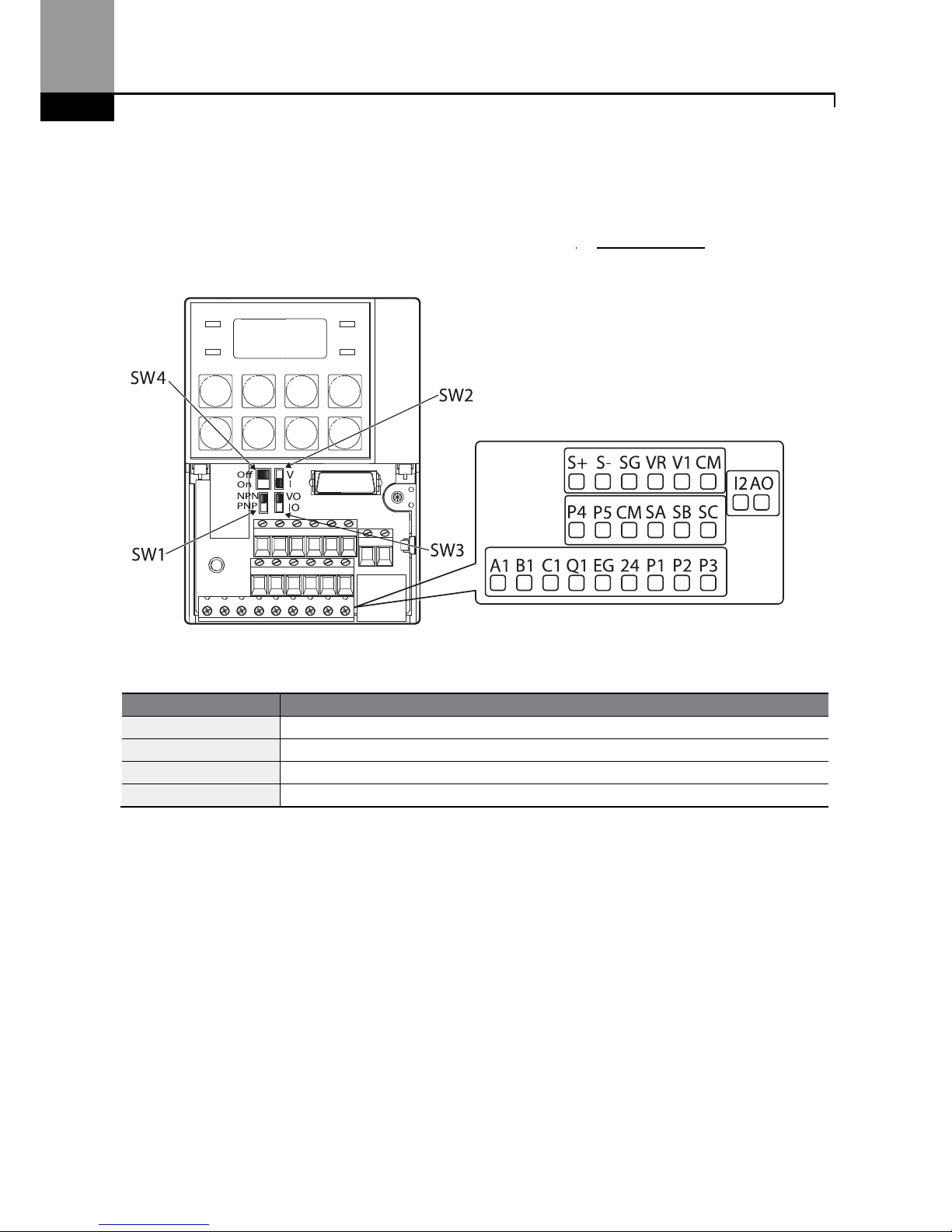
Step 4 Control Terminal Wiring
The illustrations below show the detailed layout of control wiring terminals, and control board
switches. Refer to the detailed information provided below and 1.5 Cable Selection before installing
control terminal wiring and ensure that the cables used meet the required specifications.
<Standard I/O>
Control Board Switches
S
witch
Description
SW1
NPN
/
PNP
mode
selection switch
SW2
analog
voltage
/
current
input
terminal
selection switch
SW3
analog
voltage
/
current
output
terminal
selection switch
SW4
Terminati
ng Resistor selection switch

27
Installing the Inverter
<Standard I/O>
Input Terminal Labels and Descriptions
Funct
ion Label
Name
Description
Multi-function
terminal
configuration
P1–P5
Multi-function Input 1-7
Configurable for multi
-function input
terminals. Factory default terminals
and setup are as follows:
•
P1: Fx
•
P2: Rx
•
P3: BX
•
P4: RST
•
P5: Speed-L
Standard I/O includes up to P5
only.
CM
Common
Sequence
Common terminal for analog
terminal inputs and outputs.
Analog input
configuration
VR
Potentiometer frequency
reference input
Used to setup or modify a
frequency
reference via analog voltage or
current input.
Relay output
Default: Trip
Multi-function input
Default:
Analog input
Safety function
Power
Analog output
Default: Frequency
RS-485
Terminating resistor
Installing the Inverter
28
Funct
ion Label
Name
Description
•
Maximum Voltage Output: 12V
•
Maximum Current Output:
100mA,
•
Potentiometer: 1–5kΩ
V1
Voltage input for frequency
reference input
Used to set
up or modify a
frequency
reference via analog voltage input
terminal.
•
Unipolar: 0–10V (12V Max.)
•
Bipolar: -10–10V (±12V Max.)
I2
Voltage/current input for
frequency reference input
Used to setup or modify a
frequency
reference via analog voltage or
current input terminals.
Switch between voltage (V2) and
current (I2) modes using a control
board switch (SW2).
V2 Mode:
•
Unipolar: 0–10V (12V Max.)
I2 Mode
•
Input current: 4–20mA
•
Maximum Input current: 24mA
•
Input resistance: 249Ω
TI
Pulse input for frequency
reference input (pulse train)
Setup or modify
frequency
references using pulse inputs from 0
to 32kHz.
•
Low Level: 0–2.5V
•
High Level: 3.5–12V
(For Standard I/O, Pulse input TI and
Multi-function terminal P5 share the
same terminal. Set the ln.69 P5
Define to 54(TI).).
Safety functionality
configuration
SA Safety input A
Used to block the output from the
inverter in an emergency.
Conditions:
•
Normal Operation: Both the SA
and SB terminals are connected
to the SC terminal.
•
Output Block: One or both of
the SA and SB terminals lose
connection with the SC
terminal.
SB Safety input B
SC Safety in
put power source
DC 24V,
<
25mA

29
Installing the Inverter
Output/Communication Terminal Labels and Descriptions
Function
Label
Name
Description
Analog output
AO
Voltage/Current
Output
Used to send inverter output information
to external
devices: output frequency, output current, output
voltage, or a DC voltage.
Operate switch (SW3) to select the signal output type
(voltage or current) at the AO terminal.
Output Signal Specifications:
•
Output voltage: 0–10V
•
Maximum output voltage/current: 12V/10mA
•
Output current: 0–20mA
•
Maximum output current: 24mA
•
Factory default output: Frequency
TO Pulse Output
Se
nds pulse signals to external devices to provide a
single output value from the inverter of either: output
frequency, output current, output voltage, or DC
voltage.
Output Signal Specifications:
•
Output frequency: 0–32kHz
•
Output voltage: 0–12V
•
Factory default output: Frequency
For Standard I/O, Pulse output TO and Multi-function
output Q1 share the same terminal. Set the OU.33Q1
Define to 38(TO).)
When connecting to a pulse between the inverters,
• Multiple I/O< -> Multiple I/O : Connect to TO -
>
TI, CM -> CM
• Standard I/O <-> Standard I/O : Connect to Q1
-> P5, EG -> CM
• Multiple I/O <-> Standard I/O : Do not support.
Digital output
Q1
Multi
-
functional
(open collector)
DC 26V, 100mA or less
Factory default output: Run
EG Common
Common ground
contact for an open collector (with
external power source)
24
External 24V
power source
Maximum output current: 150mA
A1/C1/B1
Fault signal
output
Sends out alarm signals when the inverter’s safety
features are activated (AC 250V <1A, DC 30V < 1A).
•
Fault condition: A1 and C1 contacts are
connected (B1 and C1 open connection)
•
Normal operation: B1 and C1 contacts are
connected (A1 and C1 open connection)
Communication S+/S-/SG RS-485 signal line
Used to send or receive RS
-
485 signals. Refer to
7 RS
-
485 Communication Ffor more details.

Installing the Inverter
30
Preinsulated Crimp Terminal Connectors (Bootlace Ferrule) .
Use preinsulated crimp terminal connectors to increase reliability of the control terminal wiring.
Refer to the specifications below to determine the crimp terminals to fit various cable sizes.
Cable Spec.
Dimensions
(inches/mm
)
AWG
mm2 L* P d1 D
26 0.25
10.4
0.4 /
6.0
0.04 /
1.1
0.1 /
2.5
12.4
0.5 /
8.0
22 0.50 12.0
0.45 /
6.0
0.05 /
1.3
0.125
/ 3.2
20 0.75 12.0
0.45 /
6.0
0.06 /
1.5
0.13 /
3.4
* If the length (L) of the crimp terminals exceeds 0.5” (12.7mm) after wiring, the control terminal
cover may not close fully.
To connect cables to the control terminals without using crimp terminals, refer to the following
illustration detailing the correct length of exposed conductor at the end of the control cable.
Note
•
While making wiring connections at the control terminals, ensure that the total cable length
does not exceed 165ft (50m).
•
Ensure that the length of any safety related wiring does not exceed 100ft (30m).
•
Ensure that the cable length between an LCD keypad and the inverter does not exceed 10ft
0.2”

31
Installing the Inverter
(3.04m)
. C
able connection
s longer than 10ft
(3.04m)
may cause signal errors.
•
Use ferrite material to protect signal cables from electro-magnetic interference.
•
Take care when supporting cables using cable ties, to apply the cable ties no closer than 6
inches from the inverter. This provides sufficient access to fully close the front cover.
•
When making control terminal cable connections, use a small flat-tip screw driver (0.1in wide
(2.5mm) and 0.015in thick (0.4mm) at the tip).
SA,SB, SC, they are shorted, have 24V voltage.
Do not connect power to the inverter until
installation has been fully completed and the inverter is ready to be operated. Doing so may result in
electric shock.
Step 5 PNP/NPN Mode Selection
The ”S” Series inverter supports both PNP (Source) and NPN (Sink) modes for digital inputs at the
terminals. Select an appropriate mode to suit requirements using the PNP/NPN selection switch
(SW1) on the control board. Refer to the following information for detailed applications.
PNP Mode (Source)
Select PNP using the PNP/NPN selection switch (SW1). Note that the factory default setting is NPN
mode. CM is is the common ground terminal for all analog inputs at the terminal, and P24 is 24V
internal source. If you are using an external 24V source, build a circuit that connects the external
source (-) and the CM terminal.
0.1” or less
0.015” or less

Installing the Inverter
32
+
NPN Mode (Sink)
Select NPN using the PNP/NPN selection switch (SW1). Note that the factory default setting is
NPN mode. CM is is the common ground terminal for all analog inputs at the terminal, and P24 is
24V internal source.

33
Installing the Inverter
Step 6 Disabling the EMC Filter for Power Sources with Asymmetrical Grounding
An EMC filter prevents electromagnetic interference by reducing radio emissions from the
inverter. EMC filter use is not always recommended, as it increases leakage current. If an inverter
uses a power source with an asymmetrical grounding connection, the EMC filter MUST be
disconnected.
Asymmetrical Grounding
Connect
ion
One phase
of a delta
connectio
n is
grounded
Intermediat
e grounding
point on
one
phase of a
delta
connection
The end
of
a single
phase is
grounded
A 3-phase
connection
without
grounding
•
Do not use the EMC filter if the inverter uses a power source with an asymmetrical grounding
structure, for example a grounded delta connection. Personal injury or death by electric shock
may result.
•
Wait at least 10 minutes before opening the covers and exposing the terminal connections.
Before
starting work on the inverter, test the connections to ensure all DC voltage has been fully
discharged. Personal injury or death by electric shock may result.
Before using the inverter, confirm the power supply’s grounding system. Disable the EMC filter if
the power source has an asymmetrical grounding connection. Refer to the figures below to locate
the EMC filter on/off terminal and replace the metal bolt with the plastic bolt. If the EMC filter is
required in the future, reverse the steps and replace the plastic bolt with the metal bolt to reconnect
the EMC filter.

Installing the Inverter
34
Step 7 Re-assembling the Covers and Routing Bracket
Re-assemble the cable routing bracket and the covers after completing the wiring and basic
configurations. Note that the assembly procedure may vary according to the product group or
frame size of the product.
Steel bolt Plastic bolt

35
Installing the Inverter
Post-Installation Checklist
After completing the installation, check the items in the following table to make sure that the
inverter has been safely and correctly installed.
Items
Check Point
Ref. Result
Installation Location/Power
I/O Verification
Is the instal
lation location appropri
ate? p.4
Does the environment
meet
the
inverter’s operating conditions?
p.5
Does the power source match the
inverter’s rated input?
p.351
Is the invert
er’s rated output su
fficient
to supply the equipment?
(Degraded performance will result in
certain circumstances. Refer to 11.7
Continuous Rated Current D for details.
p.351
Power Terminal Wiring
I
s a circuit br
eaker installed on the
input side of the inverter?
p.12
Is the circuit breaker
correctly
rated
? p.
351
Are
the power source cables
correctly
connected to the R/S/T terminals of
the inverter?
(Caution: connecting the power source
to the U/V/W terminals will damage
the inverter.)
p.22
Are
the
motor
output
cables
connected in the correct phase
rotation (U/V/W)?
(Caution: motors will rotate in reverse
direction if three phase cables are not
wired in the correct rotation.)
p.22
Are the
cables used in the power
terminal connections correctly rated?
p.9
I
s the inverter grounded
co
rrectly
?
p.21
Are the power terminal screws and
the ground terminal screws
tightened to their specified torques?
p. 22
Are the ov
erload pro
tection circuits
installed correctly on the motors (if
multiple motors are run using one
inverter)?
-
Is the inverter separated from the
power source by a magnetic
contactor (if a braking resistor is in
p.12

Installing the Inverter
36
Items
Check Point
Ref. Result
use)?
Are power factor correction
capacitor
s
,
surge protection and electromagnetic
interference filters installed correctly?
(These devices MUST not be installed
on the output side of the inverter.)
p.22
Control Terminal Wiring
Are STP (shielded twisted pair)
cables used for control terminal
wiring?
-
Is the shielding of the STP wiring
properly grounded?
-
If 3-wire operation is required,
are the
multi-function input terminals
defined prior to the installation of
the
control wiring connections?
p.26
Are the control cables properly
wired?
p26
Are the control terminal screws
tightened to their specified torques?
p.17
Is the total
cable
length of
all control
wiring < 165ft (100m)?
p.24
Is the total length of
s
afety wiring
<
100ft (30m)?
p.24
Miscellaneous
Are option
al card
s connected
correctly?
-
Is there any debris
left inside the
inverter?
p.17
Are any cables
contacting
adjacent
terminals, creating a potential short
circuit risk?
-
Are the control terminal
c
onnections
separated from the power terminal
connections?
-
Have
the capacitors been replaced if
they have been in use for > 2 years?
-
Have
the
fans been replaced if they
have been in use for > 3 years?
-
Has
a fuse
been
installed for the
power source?
p.363
Are the connections
to the
motor
separated from other connections?
-

37
Installing the Inverter
Note
STP (Shielded Twisted Pair) cable has
a
highly conductive
, shielded
screen around twisted
cable
pairs.
STP cables protect conductors from electromagnetic interference.
Test Run
After the post-installation checklist has been completed, follow the instructions below to test the
inverter.
1 Turn on the power supply to the inverter. Ensure that the keypad display light is on.
2 Select the command source.
3 Set a frequency reference, and then check the following:
•
If V1 is selected as the frequency reference source, does the reference change according to
the input voltage at VR?
•
If V2 is selected as the frequency reference source, is the voltage/current selector switch
(SW2) set to voltage, and does the reference change according to the input voltage?
•
If I2 is selected as the frequency reference source, is the voltage/current selector switch
(SW2) set to current, and does the reference change according to the input current?
4 Set the acceleration and deceleration time.
5 Start the motor and check the following:
•
Ensure that the motor rotates in the correct direction (refer to the note below).
•
Ensure that the motor accelerates and decelerates according to the set times, and that the
motor speed reaches the frequency reference.
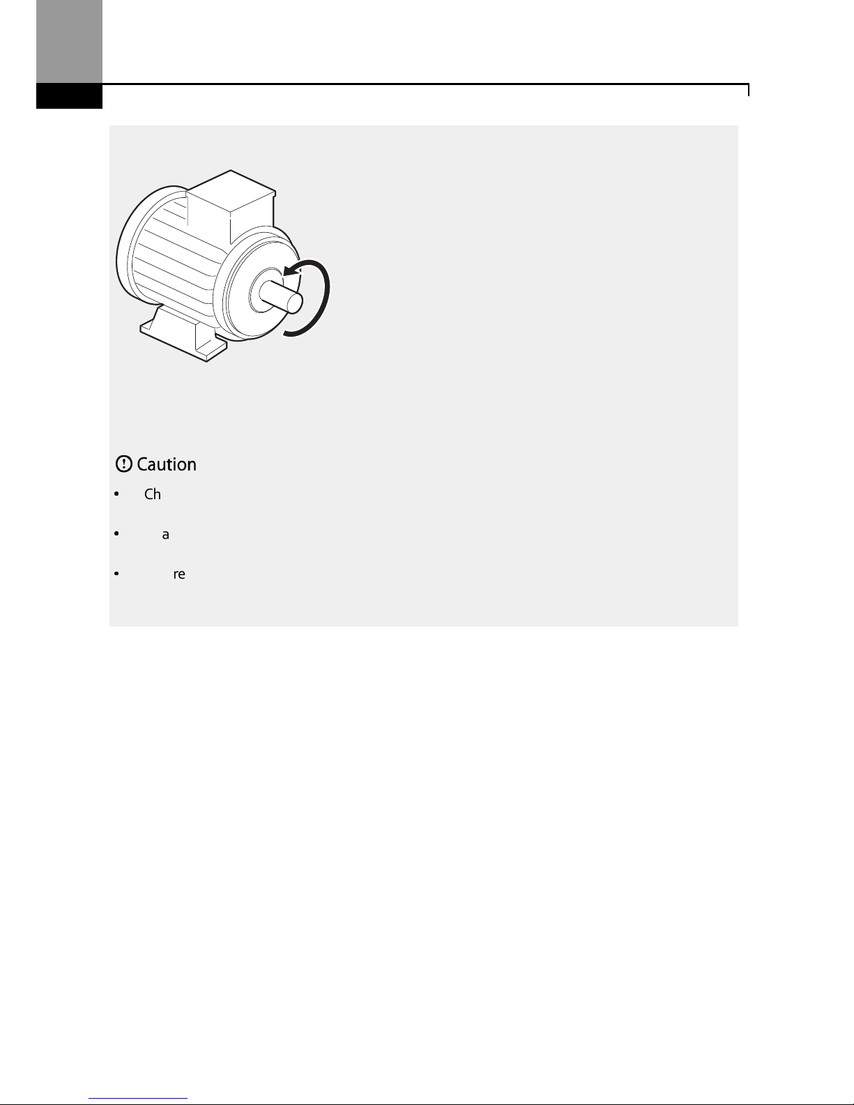
N
ote
If the forward command (
Fx) is on, the motor should rotate counterclockwise when viewed from
the load side of the motor. If the motor rotates in the reverse direction, switch the cables at the
U
and V terminals.
Verifying the
Motor
Rotation
1 On the keypad, set the drv (Frequency reference source) code in the Operation group to 0
(Keypad).
2 Set a frequency reference.
3 Press the [RUN] key. Motor starts forward operation.
4 Observe the motor’s rotation from the load side and ensure that the motor rotates
counterclockwise (forward).
Installing the Inverter
38
If the motor r
otates
in the reverse direction, two of the U/V/W terminals need to be switched.
•
Check the parameter settings before running the inverter. Parameter settings may have to be
adjusted depending on the load.
•
To avoid damaging the inverter, do not supply the inverter with an input voltage that exceeds
the rated voltage for the equipment.
•
Before running the motor at maximum speed, confirm the motor’s rated capacity. The “S” Series
inverters can be used to easily increase motor speed, use caution to ensure that motor speeds
do
not accidently exceed the motor’s rated capacity.
Forward operation
Learning Advanced Features
39
3 Learning to Perform Basic Operations
This chapter describes the keypad layout and functions. It also introduces parameter groups and
codes required to perform basic operations. The chapter also outlines the correct operation of the
inverter before advancing to more complex applications. Examples are provided to demonstrate
how the inverter actually operates.
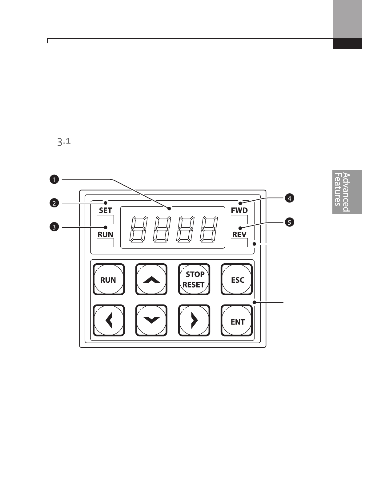
About the Keypad
The keypad is composed of two main components – the display and the operation (input) keys.
Refer to the following illustration to identify part names and functions.
Display
Keys
Learning Advanced Features
40
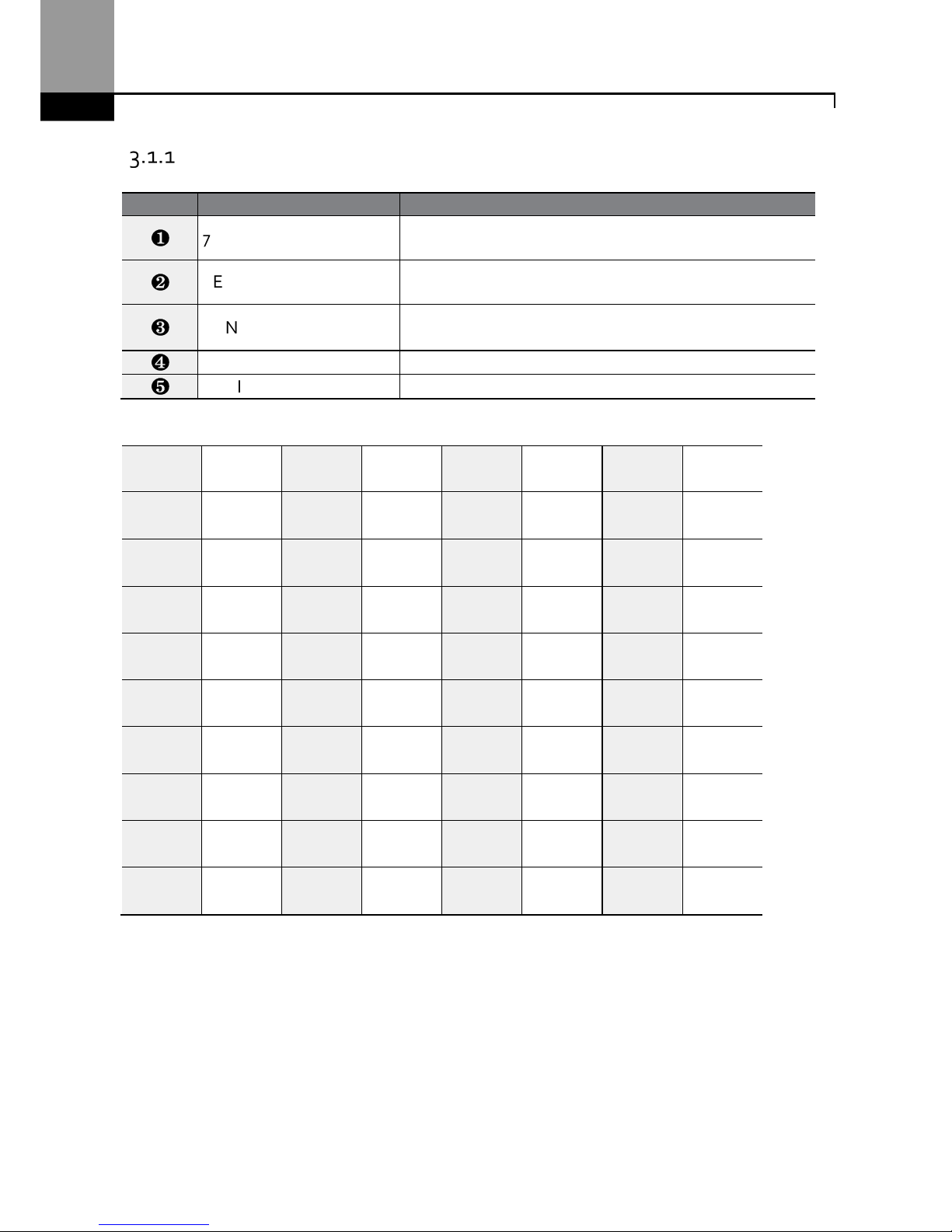
About the Display
The following table lists display part names and their functions.
No. Name
Function
❶
7-Segment Display
Displays current operational status and parameter
information.
❷
SET Indicator
LED
flashes
during parameter configuration and when the
ESC key operates as the multi-function key.
❸
RUN Indicator
LED t
urns on (steady) during an operation, and
flashes
during acceleration or deceleration.
❹
FWD Indicator
LED t
urns on (steady) during for
ward operation.
❺
REV Indicator
LED t
urns on (steady) during reverse operation.
The table below lists the way that the keypad displays characters (letters and numbers).
0
0
a
A
k
K
u
U
1
1
b
B
l
L
v
V
2
2
c
C
m
M
w
W
3
3
d
D
n
N
x
X
4
4
e
E
o
O
y
Y
5
5
f
F
p
P
z
Z
6
6
g
G
q
Q - -
7
7
h
H
r
R - -
8
8
i
I
s
S - -
9
9
j
J
t
T - -
Learning Advanced Features
41
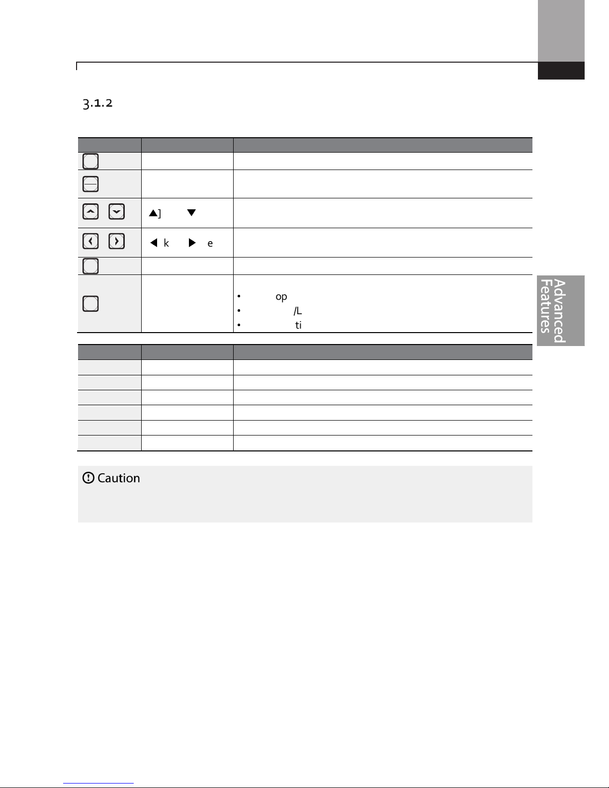
Operation Keys
The following table lists the names and functions of the keypad’s operation keys.
Install a separate emergency stop switc
h in t
he
circuit
. The [STOP/RESET] key on the keypad works
only when the inverter has been configured to accept an input from the keypad.
Key Name
Description
[RUN] key Used to run the inverter (inputs a RUN command).
[STOP/RESET] key
STOP: stops the inverter.
RESET: resets the inverter following fault or failure condition.
,
[▲] key, [▼] key
Switch between codes, or to increase or decrease parameter
values.
,
[◀] key, [▶] key
Switch between groups, or to move the cursor during
parameter setup or modification.
[ENT] key
Used to select, confirm, or save a parameter value.
[ESC] key
A multi
-
function key used to configure different functions, such as:
•
Jog operation
•
Remote/Local mode switching
•
Cancellation of an input during parameter setup
RUN
STOP
RESET
ENT
ESC

Learning Advanced Features
42
Control Menu
The ”S” Series inverter control menu uses the following groups.
Group
Display
Description
Operation
-
C
onfigure
s basic parameters for inverter operation
.
These include reference source , control source,
acceleration/deceleration times, etc. The actual
speed (frequencies) during acceration and
deceleration will not be displayed on the 7-segment
(LED) display, only if an LCD keypad is in use.
Drive
dr
C
onfigure
s parameters for basic operations
. These
include jog operation, motor capacity evaluation,
torque boost, and other keypad related parameters.
Basic
ba
C
onfigure
s basic parameters,
including
motor
-
related parameters and multi-step frequencies.
Advanced
ad
C
onfigur
e acceleration or deceleration patterns
and to setup frequency limits.
Control
cn
Configures sensorless vector - related features.
Input Terminal
in
Configures
input terminal
–
related features
,
including digital multi–functional inputs and
analog inputs.
Output Terminal
ou
Configures
output terminal
–
related features such
as relays and analog outputs.
Communication
cm
Configures communication
features
for RS-485 or
other communication options.
Application
ap
Configures
PID control
–
related sequ
ences and
operations.
Protection
pr
Configures motor or inverter protection features.
Motor 2 (Secondary Motor)
m2
C
onfigure
s secondary
motor
related features.
The
secondary motor (M2) group
appears on the keypad
only when one of the multi-function input terminals
(In.65–In.71) has been set to 26 (Secondary motor).
User Sequence
us
Used to implement simple sequences with various
function blocks.
User Sequence Function
uf

Learning Advanced Features
43
Learning to Use the Keypad
The keypad enables movement between groups of parameters and the parameters within each
group. At code level, you can set parameter values and turn on or off specific functions. Refer to 8
on page 255 to find the functions you need.
Confirm the correct values (or the correct range of the values), and then follow the examples below
to configure the inverter with the keypad.
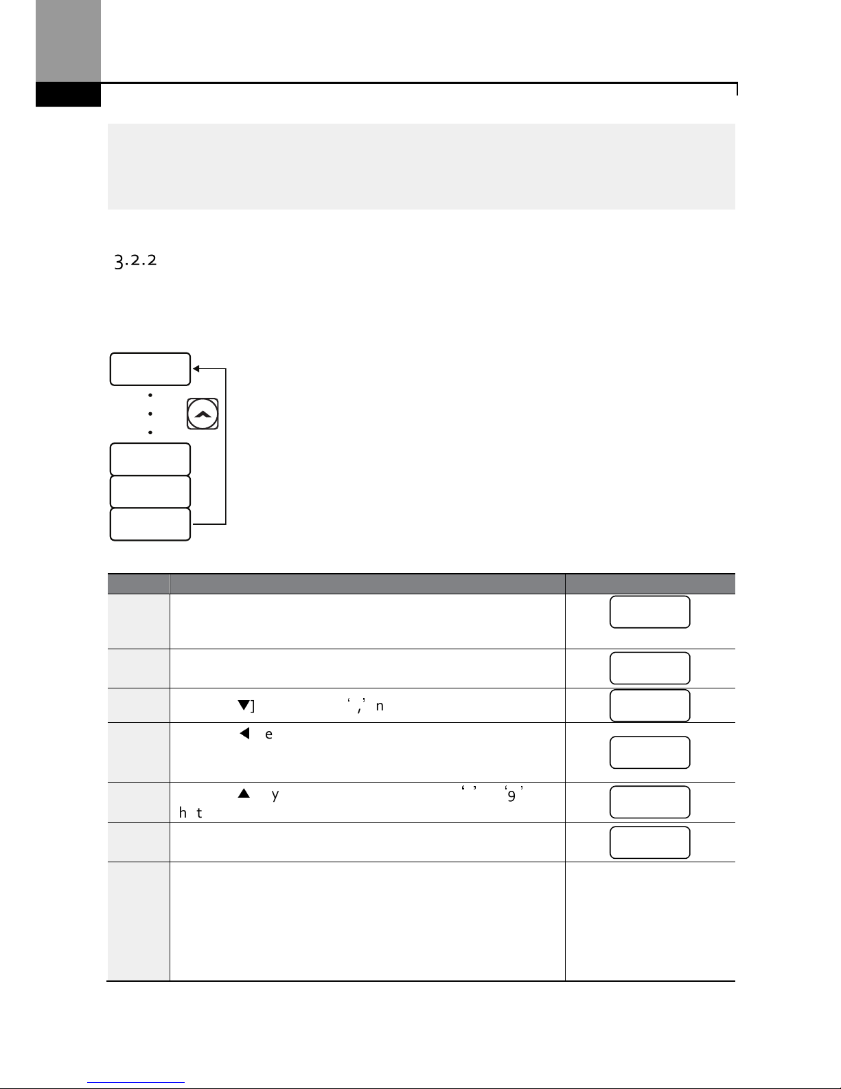
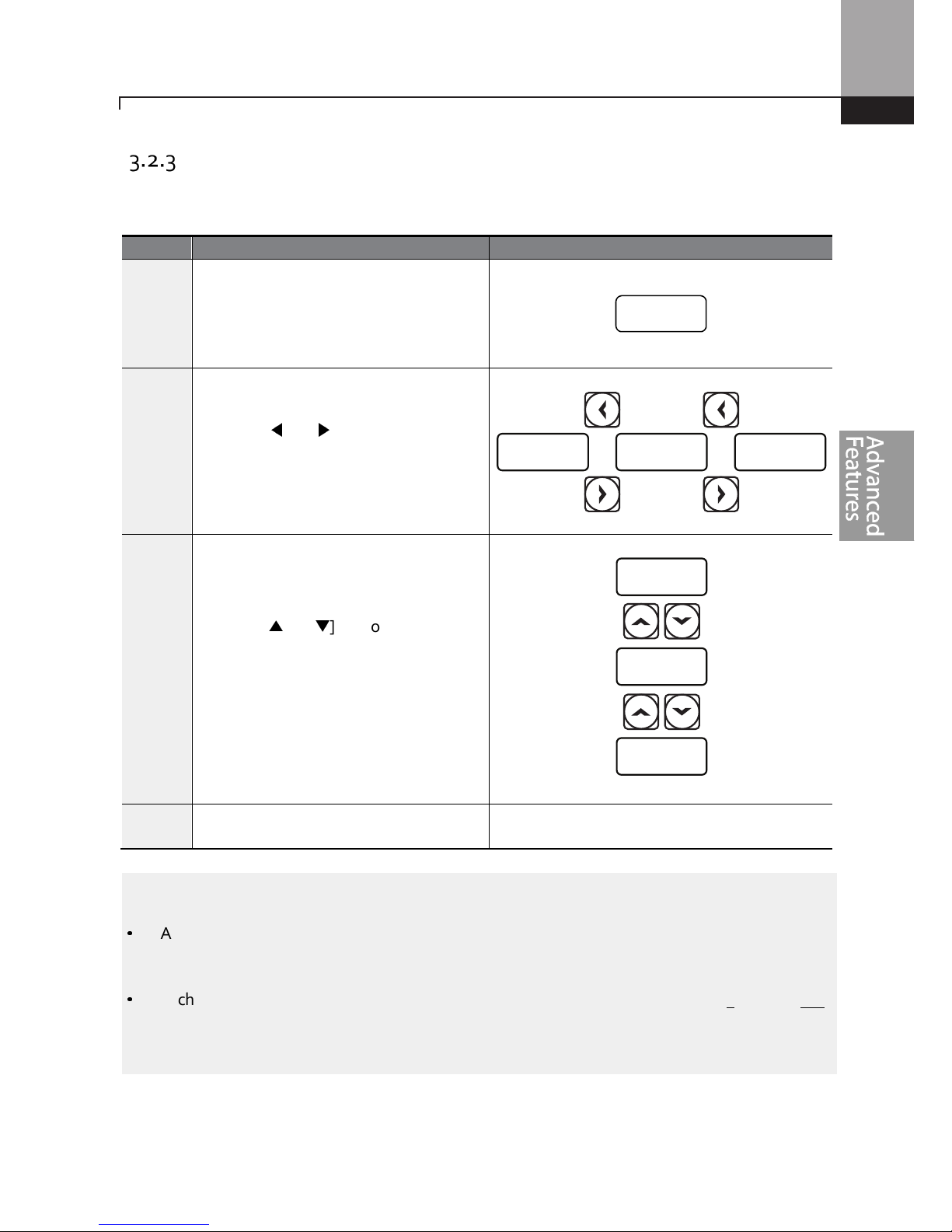
Group and Code Selection
Follow the examples below to switch between groups and codes.
Step
Instruction
Keypad Display
1
Move to the group you
want using the [◀] and
[▶] keys.
2
Move up and down
through the codes using
the [▲] and [▼] keys
until you locate the
code that you require.
Note
For some settings, pressing the [▲] or [▼] key may skip choices . This is because certain code numbers
have been intentionally left blank (or reserved) for new functions to be added in the future. Also some
features may have been hidden (disabled) because a certain code has been set to disable the functions
for relevant codes.
CM
AP IN
UF DR
0.00
PR CN
US BA
M2 AD
OU
0.00
DEC
DRC
ACC
0.00
Learning Advanced Features
44
As an example
, i
f Ad.
24 (Frequency Limit)
is set
to 0 (No), the
next codes, Ad.
25 (Freq Limit Lo) and
Ad.26 (Freq Limit Hi), will not be displayed. If you set code Ad.24 to 1 (Yes), this enables the frequency
limit features, codes Ad.25 and 26 will appear to allow the maximum and minimum frequency
limitations to be set up.
Navigating Directly to Different Codes
The following example details navigating to code dr. 95, from the initial code in the Drive group (dr.
0). This example applies to all groups whenever you would like to navigate to a specific code
number.
Step
Instruction
Keypad Display
1
Ensure that you are currently at the first code of the Drive group
(dr.0).
2
Press the [ENT] key.
Number ‘9’ will flash. (default setting)
3
Press the [▼] key to display ‘5,’ in the ones position.
4
Press the [◀] key to move to the tens position.
The cursor will move to the left and ‘05’ will be displayed. This
time the number ‘0’ will be flashing.
5
Press the [▲] key to increase the number from ‘0’ to ‘9,’ in
the tens position .
6
Press the [ENT] key.
Code dr.95 is displayed.
DR.95
DR. 8
DR. 2
DR. 0
‘9’
‘
5’
‘0’5
‘9’5
dr.95
dr.0
Learning Advanced Features
45
Setting Parameter Values
Follow the instructions below to set or modify parameter values.
Note
•
A flashing number on the display indicates that the keypad is waiting for an input from the user.
Changes will be saved when the [ENT] key is pressed while the number is flashing. The setting
change will be canceled if you press any other key.
•
Each code’s parameter values have default features and ranges specified. Refer to 8 on page 255
for information about the features and ranges before setting or modifying parameter values.
Step
Instruction
Keypad Display
1
Select the group and code to setup or
modify. Press the [ENT] key (The SET
LED will flash indicating Program mode).
The first number on the right side of the
display will flash.
2
Press the [◀] or [▶] key to move the
cursor to the number that you would like
to modify.
3
Press the [▲] or [▼] key to adjust the
value, and then press the [ENT] key to
confirm it.
The selected value will flash on the
display.
4
Press the [ENT] key again t
o save the
change.
-
)5.0 %.0 5.)
^.0
%.0
$.0
5.’0’

Learning Advanced Features
46
Configuring the [ESC] Key
The [ESC] key is a multi-functional key that can be configured to carry out a number of different
functions. Refer to 4.6 Local/Remote Mode Switch for more information about the other functions of
the [ESC] key. The following example shows how to configure the [ESC] key to perform a jog
operation.
Step
Instruction
Keypad Display
1
En
sure that you are currently at the first code of the
Operation
group, and that code 0.00 (Command Frequency) is displayed.
2
Press the [▶] key.
You have moved to the initial code of the Drive group (dr.0).
3
Press the [▲] or [▼] key to select code dr.90 (ESC key
configuration), and then press the [ENT] key.
Code dr.90 currently has an initial parameter value of 0.
4
Press the [▲] key to modify the value to 1 (Jog key) and then
press the [ENT] key.
The new parameter value will flash.
5 Press the [ENT] key again to save changes
. -
Note
•
If the code dr. 90 (ESC key configuration) is set to 1 (JOG Key) or 2 (Local/Remote), the SET
indicator will flash when the [ESC] key is pressed.
•
The factory default setting for code dr. 90 is 0 (move to the initial position). You can navigate back
to the initial position (code 0.00 of the Operation group) immediately, by pressing the [ESC] key
while configuring any codes in any groups.
DR.90 ) !
ENT
ENT
DR. 2
DR. 00.00
0.00
dr.0
0
dr.90
‘1’

Learning Advanced Features
47
Application Examples
Acceleration Time Configuration
The following is an example demonstrating how to modify the ACC (Acceleration time) code value
(from 5.0 to 16.0) from the Operation group.
ACC
0.00
5.0 16.0
ENT
ENT
ENT
Step
Instruction
Keypad Display
1
Ensure th
at the first code of the Operation group is displayed and
code 0.00 (Command Frequency) is displayed.
2
Press the [▲] key.
The display will change to the second code in the Operation
group, the ACC (Acceleration Time) code.
3
Press the [ENT] key.
The number ‘5.0’ will be displayed, with ‘0’ flashing. This indicates
that the current acceleration time is set to 5.0 seconds. The
flashing value is ready to be modified by using the keypad.
4
Press the [◀] key to move to the left.
‘
5’ will be flashing now. This indicates the flashing value, ‘5’ is
ready to be modified.
5
Press the [▲] key to change the number ‘5’ to ‘6’, in the one’s
place.
6
Press the [◀] key to move to the tens place.
The number in the tens position, ‘0’ in ‘06’ will start to flash
7
Press the [▲] key to change the number from ‘0’ to ‘1’, to
match the tens place and then press the [ENT] key.
Both digits will flash on the display.
8
Press the [ENT] key once again to save changes.
‘
ACC’ will be displayed. The change to the acceleration time
setup has been completed.
0.00
acc
5.’0’
‘5’.0
‘6’.0
‘0’6.0
‘16’.0
acc

Learning Advanced Features
48
Frequency Reference Configuration
The following is an example to demonstrate configuring a frequency reference of 30.05 (Hz) from
the first code in the Operation group (0.00).
0.00 30.00 30.05
ENT
ENT ENT
Step Instruction
Keypad
Display
1
Ensure that the first code of the Operation group is selected, and the code 0.00
(Command Frequency) is displayed.
2
Press the [ENT] key.
The value, 0.00 will be displayed with the ‘0’ in the hundredths place value
flashing.
3
Press the [◀] key 3 times to move to the tens place.
The ‘0’ at the tens place will start to flash.
4
Press the [▲] key to change it to ‘3’.
5
Press the [▶] key 3 times.
The ‘0’ at the hundredths place position will flash.
6
Press the [▲] key to change it to ‘5’.
The parameter value will flash on the display.
7
Press the [ENT] key to save changes.
Flashing stops. The frequency reference has been configured to 30.05 Hz.
Note
•
A flashing number on the display indicates that the keypad is waiting for input from the user.
Changes are saved when the [ENT] key is pressed while the value is flashing. Changes will be
canceled if any other key is pressed.
•
The ”S” Series inverter keypad display can display up to 4 digits. However, 5-digit figures can be
used and are accessed by pressing the [◀] or [▶] key, to allow keypad input.
0.00
0.0’0’
‘0’0.00
30.00
30.0’0’
30.0’5’
30.05

Learning Advanced Features
49
Jog Frequency Configuration
The following example demonstrates how to configure Jog Frequency by modifying code dr.11 in
the Drive group (Jog Frequency) from 10.00(Hz) to 20.00(Hz). You can configure the parameters for
different codes in any other group in exactly the same way.
Step
Instruction
Keypad Display
1 Go to code 11(Jog Frequency) in the Drive group.
2
Press the [ENT] key
.
The current Jog Frequency value (10.00) for code dr.11 is
displayed.
3
Press the [◀] key 3 times to move to the tens place.
Number ‘1’ at the tens place will flash.
4
Press the [▲] key to change the value to ‘2,’ in the tens place
and then press the [ENT] key.
All parameter digits will flash on the display.
5
Press the [ENT] key once again to save
the
changes
.
Code dr.11 will be displayed. The parameter change has been
completed.
DR.11
@),))
10.0) @0.00!0.00
ENT
ENT ENT
dr.11
10.00
‘1’
0.00
’20.00’
dr.11

Learning Advanced Features
50
Initializing All Parameters
The following example demonstrates parameter initialization using code dr.93 (Parameter
Initialization) in the Drive group. Once executed, parameter initialization will delete all modified
values for all codes and groups.
Step
Instruction
Keypad Display
1 Go to code 0 (Jog Frequency) in the Drive group.
2
Press the [ENT] key
.
The current parameter value (9) will be displayed. (default
setting)
3
Press the [▼] key to change the ones place to ‘3’ of the target
code, ’93.’
4
Press the [◀] key to move to the tens place.
‘
03’ will be displayed.
5
Press the [▲] or [▼] key to change the ‘0’ to ‘9’ of the target
code, ’93.’
6
Press the [ENT] key.
Code dr.93 will be displayed.
7
Press the [ENT] key once again.
The current parameter value for code dr.93 is set to 0 (Do not
initialize).
8
Press the [▲] key to change the value to 1 (All Grp), and then
press the [ENT] key.
The parameter value will flash.
9
Press the [E
NT] key once again.
Parameter initialization begins. Parameter initialization is
complete when code dr.93 reappears on the display.
Note
Following parameter initialization, a
ll parameters are re
set to factory default values.
Ensure
that
parameters are reconfigured before running the inverter again after an initialization.
ENT
ENT
OR OR
DR.93 ) !
DR. 0 ( )3# (3
dr.0
9
3
0
3
9
3
dr.93
0
1
dr.93

Learning Advanced Features
51
Frequency Setting (Keypad) and Operation (via Terminal Input)
Step
Instruction
Keypad Display
1 Turn on the inverter.
-
2
Ensure that the first code of the Operation group is selected,
and code 0.00 (Command Frequency) is displayed, then press
the [ENT] key.
The first digit on the right will flash.
3
Press the [◀] key 3 times to go to the tens place.
The number ‘0’ at the tens place will flash.
4
Press the [▲] key to change it to 1, and then press the [ENT]
key.
The parameter value (10.00) will flash.
5
Press the [ENT] key once again to save changes.
A change of reference frequency to 10.00 Hz has been
completed.
6
Refer to the wiring diagram at the bottom of the table, and
close the switch between the P1 (FX) and CM terminals.
The FWD indicator light comes on steady. The RUN indicator
light flashes as the drive accelerates from 0 Hz. to 10 Hz.
When the drive frequency of 10 Hz. is reached, the RUN
indicator light becomes steady (not flashing).
7
When the frequency reference is reached (10Hz), open the
switch between the P1 (FX) and CM terminals.
The RUN indicator light flashes again and the decelerating
frequency is displayed. When the frequency reaches 0Hz, the
RUN and FWD indicator lights turn off, and the frequency
reference (10.00Hz) is displayed again.
SET
RUN
FWD
REV
10.00
SET
RUN
FWD
REV
10.00
0.0’0’
‘0’0.00
’10.00’
10.00
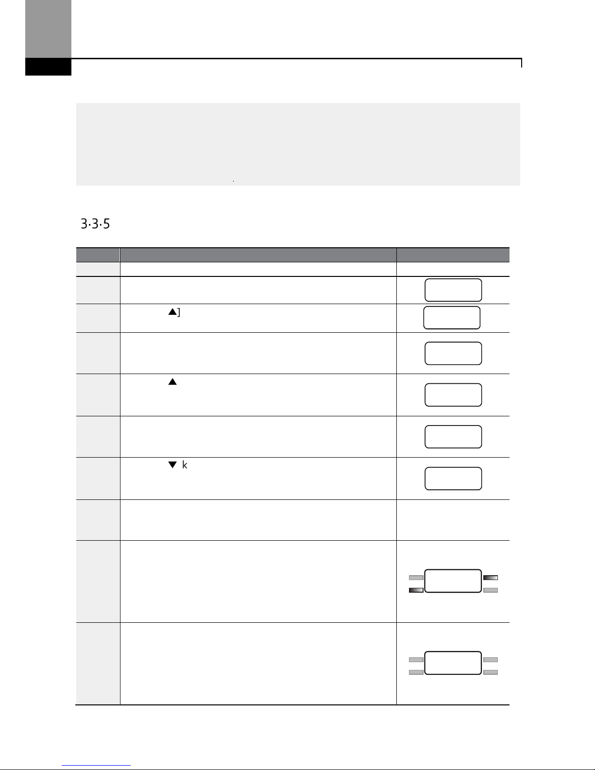
Learning Advanced Features
52
Note
The instructions in the table are based on the factory default parame
ter settings.
The inverter
may not
work correctly if the default parameter settings are changed after the inverter is purchased. In such
cases, initialize all parameters to reset the values to factory default parameter settings
before following
the instructions in the table (refer to 5.23).
Frequency Setting (Potentiometer) and Operation (Terminal
Input)
Step
Instruction
Keypad Display
1 Turn on the inve
rter. -
2
Ensure that the first code of the
Operation group
is selected,
and the code 0.00 (Command Frequency) is displayed.
3
Press the [▲] key 4 times to go to the Frq (Frequency reference
source) code.
4
Press the [ENT] key.
The Frq code in the Operation group is currently set to 0
(keypad).
5
Press the [▲] key to change the parameter value to 2
(Potentiometer), and then press the [ENT] key.
The new parameter value will flash.
6
Press the [ENT] key once again.
The Frq code will be displayed again. The frequency input has
been configured for the potentiometer.
7
Press the [▼] key 4 times.
Returns to the first code of the Operation group (0.00).From
here frequency setting values can be monitored.
8
Adjust
the
potentiometer
to verify the
frequency reference
changes. The frequency reference will change eventhough
the drive is not running yet.
-
9
Refer t
o the wiring diagram at the bottom of the table, and
close the switch between the P1 (FX) and CM terminals.
The FWD indicator light comes on steady. The RUN indicator
light flashes as the drive accelerates from 0 Hz. to the
frequency reference. When the drive frequency is reached,
the RUN indicator light becomes steady (not flashing).
10
When
the
frequency reference
is
reache
d (10
Hz),
open
the
switch between the P1 (FX) and CM terminals.
The RUN indicator light flashes again and the decelerating
frequency is displayed. When the frequency reaches 0Hz, the
RUN and FWD indicators turn off, and the frequency reference
is displayed again.
SET
RUN
FWD
REV
10.00
SET
RUN
FWD
REV
10.00
0.00
F
rq
0
‘
2’
F
rq
0.00
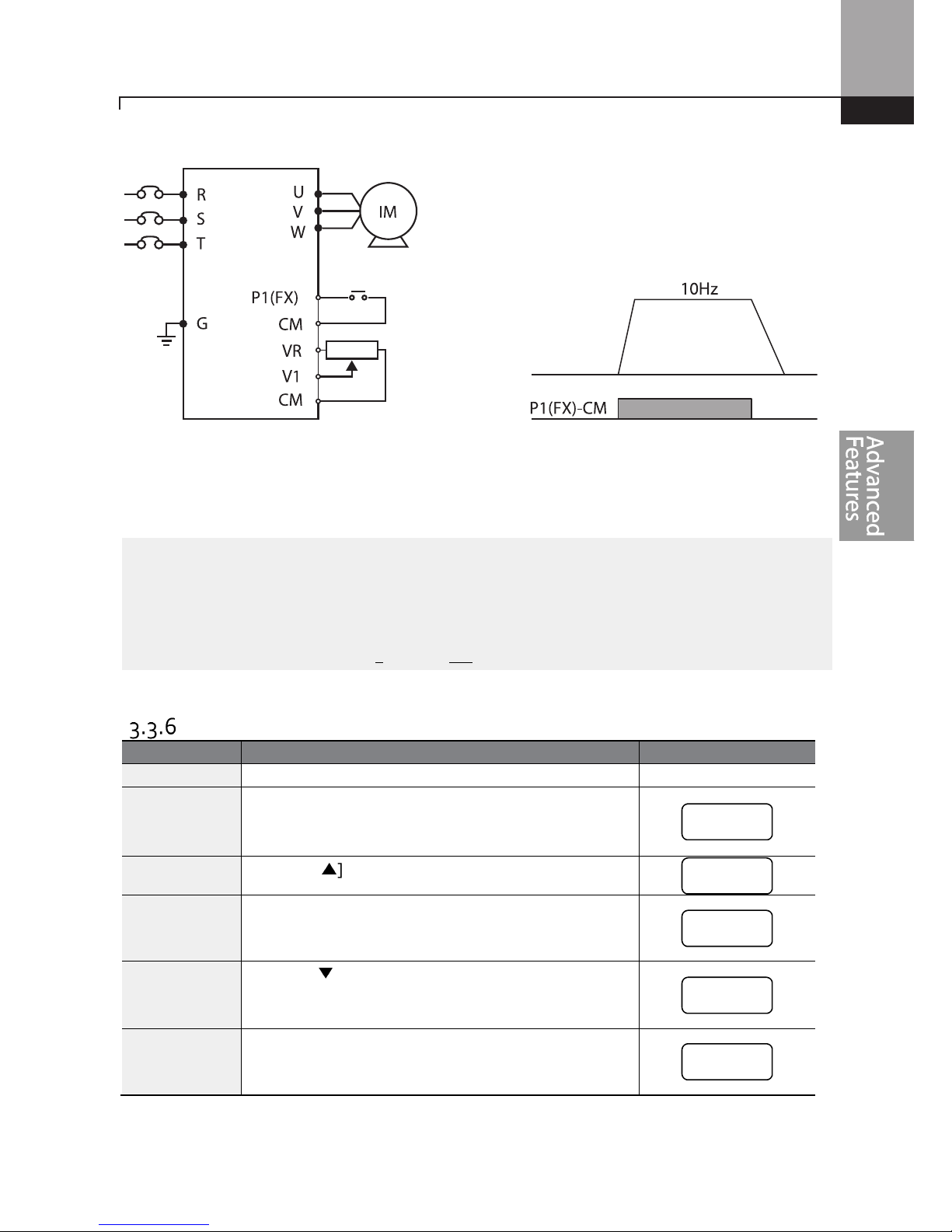
Learning Advanced Features
53
[Wiring Diagram] [Operation Pattern]
Note
The instructions in the table are based on the factory default parameter settings.
The inverter may not
work correctly if the default parameter settings are changed after the inverter is purchased. In such
cases, initialize all parameters to reset the factory default parameter settings before following the
instructions in the table (refer to 5.23 on page 183).
Frequency Setting (Potentiometer) and Operation (Keypad)
Step
Instruction
Keypad D
isplay
1
Turn on the inverter.
-
2
Ensure that the first code of the
Operation group
is
selected, and the code 0.00 (Command Frequency) is
displayed.
3
Press the [▲] key 4 times to go to the drv code.
4
Press the [ENT] key.
The drv code in the Operation group is currently set to 1
(Analog Terminal).
5
Press the [▼] key to change the parameter value to 0
(Keypad), and then press the [ENT] key.
The new parameter value will flash.
6
Press the [ENT] key once again.
The drv code is displayed again. The frequency input has
been configured for the keypad.
Frequency
0.00
drv
1
‘0’
drv

Learning Advanced Features
54
Step
Instruction
Keypad D
isplay
7
Press the [▲] key.
To move to the Frq (Frequency reference source) code.
8
Press the [ENT] key.
The Frq code in the Operation group is set to 0 (Keypad).
9
Press the [▲] key to change it to 2 (Potentiometer), and
then press the [ENT] key.
The new parameter value will flash.
10
Press the [ENT] key once again.
The Frq code is displayed again. The frequency input has
been configured for potentiometer.
11
Press the [▼] key 4 times.
Returns to the first code of the Operation group (0.00).
From here frequency setting values can be monitored.
12
Adjust the potentiometer to verify the frequency
reference changes. The frequency reference will
change eventhough the drive is not running yet.
-
13
Press the [RUN] key on the keypad.
The FWD indicator light comes on steady. The RUN
indicator light flashes as the drive accelerates from 0 Hz.
to the frequency reference. When the drive frequency
is reached, the RUN indicator light becomes steady (not
flashing).
14
When
the frequency reaches th
e reference (10Hz), press
the [STOP/RESET] key on the keypad.
The RUN indicator light flashes again and the
decelerating frequency is displayed.
When the frequency
reaches 0Hz, the RUN and FWD indicator lights turn off,
and the frequency reference is displayed again.
[Wiring Diagram] [Operation Pattern]
SET
RUN
FWD
REV
10.00
SET
RUN
FWD
REV
10.00
Frequency
key
key
frq
0
‘
2’
frq
0.00
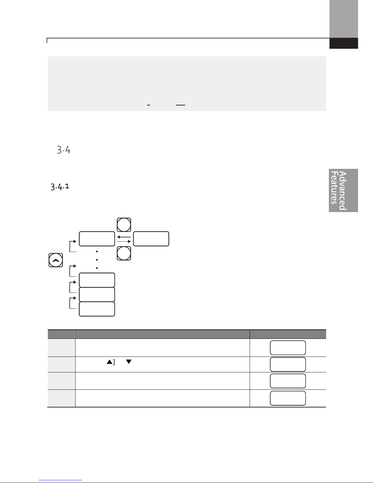
Learning Advanced Features
55
Note
The instructions in the table are based on the factory default
parameter settings.
The inverter may not
work correctly if the default parameter settings are changed after the inverter is purchased. In such
cases, initialize all parameters to reset the factory default parameter settings before following the
instructions in the table (refer to 5.23 on page 183).
Monitoring the Operation
Output Current Monitoring
The following example demonstrates how to monitor the output current in the Operation group
using the keypad.
Step
Instruction
Keypad Display
1
Ensure that the first code of the
Operation group
is selected,
and the code 0.00 (Command Frequency) is displayed.
2
Press the [▲] or [▼] key to move to the Cur code.
3
Press the [ENT] key.
The output current (5.0A) is displayed.
4
Press the [ENT] key again.
Returns to the Cur code.
CUR 5.0
ENT
ENT
DEC
ACC
0.00
0.00
cur
5.0
cur
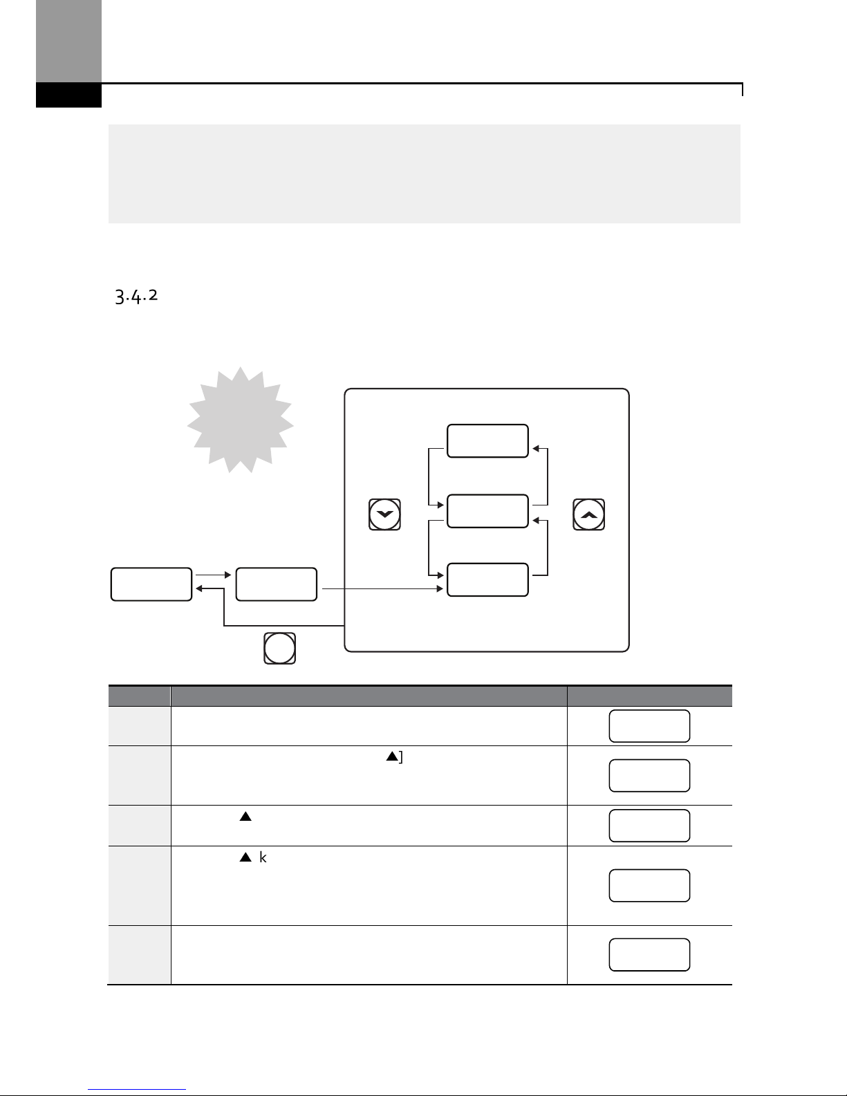
Learning Advanced Features
56
Note
You
can use the dCL (DC link voltage monitor) and
v
OL (output voltage mon
itor) codes in the
Operation group in exactly the same way as shown in the example above, to monitor each function’s
relevant values.
Fault Trip Monitoring
The following example demonstrates how to monitor fault conditions in the Operation group using
the keypad.
Step
Instruction
Keypad Display
1
Refer to t
he
example
keypad display.
An over current trip fault has occurred.
2
Press the [ENT] key, and then the [▲] key.
The operation frequency at the time of the fault (30.00Hz) is
displayed.
3
Press the [▲] key.
The output current at the time of the fault (5.0A) is displayed.
4
Press the [▲] key.
The operation status at the time of the fault is displayed. ACC
on the display indicates that the fault occurred during
acceleration.
5
Press the [STOP/RESET] key.
The inverter resets and the fault condition is cleared. The
frequency reference is displayed on the keypad.
STOP
RESET
ACC
OCT30.00
5.0
30.00
Acceleration
Current (A)
Frequency
Over current
trip
oct
30.0
0
5.0
acc
30.00
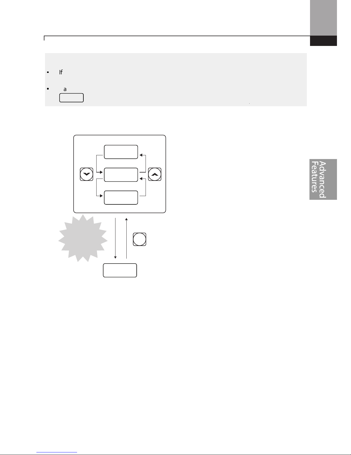
Learning Advanced Features
57
Note
•
If multiple faults occur at the same time, a maximum of 3 fault records can be retrieved as shown
in the following example.
•
If a warning condition occurs while running at a specified frequency, the current frequency and the
signal will be displayed alternately, at 1 second intervals. Refer to 6.3 for more details.
STOP
RESET
30.00
OLT
OVT
OCT
Over current
Over voltage
Over load
3
simultaneous
trips
warn

Learning Advanced Features
58

Learning Advanced Features
59
4 Learning Basic Features
This chapter describes the basic features of the ”S” Series inverter. Check the reference page in the
table to see the detailed description for each of the advanced features.
Basic
Tasks
Description
Ref.
Frequency reference
source
configuration for the keypad
Configures the inverter to allow you to setup or modify
frequency reference using the Keypad.
p.62
Frequency reference
source
configuration using V1 or V2
Configures the inverter to allow
input
voltage
s at
terminals
V1 or V2 to control the frequency reference.
p.63,
p.70
Frequency reference
source
configuration using I2
Configures the inverter to allow
input
currents at
terminal
I2 to control the frequency reference.
p.68
Frequency reference
source
configuration using TI
terminal (pulse input)
Configures the inverter to allow an input pulse at the
terminal TI to control the frequency reference.
p.71
Frequency reference
source
configuration using RS-485
communication
Configures the inverter to allow communication signals
from controllers, such as PLCs or PCs, to setup or modify a
frequency reference.
p.73
Frequency hold
c
ontrol
when
using analog inputs
Enables the user to hold a fr
equency steady with a digital
input when using analog inputs at terminals.
p.74
Motor speed display options
M
otor speed
is
displayed either in frequency (Hz) or
speed
(rpm).
p.74
Multi
-
step
speed (
frequency
)
configuration
Configures multi
-
step frequencies
using
digital
inputs
at the
terminals defined for each step frequency.
p.75
Command source
configuration for keypad
buttons
Configures inverter operation using the [FWD], [REV] and
[Stop] keys on the keypad.
p.77
Command source
(Start/Stop)
configuration for
terminal inputs
Configures inverter start/stop operation using digital inputs
at the FX/RX terminals.
p.77
Command source
configuration for RS-485
communication
Configures inverter operation from communication signals
from controllers, such as PLCs or PCs.
p.79
Local/remote switching via
the [ESC] key
Configures the inverter to switch between local and remote
operation modes when the [ESC] key is pressed.
When the inverter is operated using remote inputs (any
input other than from the keypad), this configuration can
be used to control the inverter from the keypad without
altering saved parameter settings. It overrides the remote
settings to control the inverter from the keypad in
emergency situations.
p.79
M
otor rotation
(direction)
control
Configures the inverter to prevent operating
t
he
motor
in a
specific direction.
p.81
Automatic start
-
up at power
-
on
Configures the
inverter to start operat
ing at power
-
on.
With this configuration, the inverter begins to run and the
p.81

Learning Advanced Features
60
Basic
Tasks
Description
Ref.
motor accelerates as soon as power is supplied to the
inverter. The start command must be maintained at the
Fx/Rx terminals.
Automatic restart after reset
of a fault condition
Configures the inverter to start operating
when the inverter
is reset after a fault. In this configuration, the inverter starts
to run and the motor accelerates as soon as the inverter is
reset. The start command must be maintained at the Fx/Rx
terminals.
p.82
Acc/Dec time configuration
based on the Max. Frequency
Configures the acceleration and deceleration times
for the
motor. The time scale is based on starting from a
stopped
state (0 Hz.) to the maximum frequency.
p.84
Acc/Dec time configuration
based on the frequency
reference
Configures acceleration and deceleration times
for the
motor based on the existing operating frequency to the
next frequency reference.
p.85
Mu
lti-st
age Acc/Dec time
configuration using the
multi-function terminal
Configures multi
-stage acceleration and deceleration times
for the motor based on defined parameters using the
digital input terminals.
p.86
Acc/Dec time using a switch
frequency.
Enables two independent
accelerati
on and deceleration
times below and above a set switch frequency.
p.88
Acc/Dec pattern
configuration
Enables modification of the accelera
tion and deceleration
gradient patterns. Basic patterns to choose from include
linear and S-curve patterns.
p.88
Acc/Dec stop command
Stops the current acceleration or deceleration and
controls
motor operation at a constant speed. A digital input
terminal must be configured for this command.
p.91
Linear V/F pattern operation
Configures the inverter
to run a
motor
at a constant torque.
To maintain the required torque, the operating frequency
may vary during operation.
p.91
Square reduction V/F pattern
operation
Configures the inverter
to run
the motor
at a square
reduction V/F pattern. Fans and pumps are appropriate
loads for square reduction V/F operation.
p.92
User V/F pattern
configuration
Enables the user to configure
a V/F pattern
to match the
characteristics of a motor and load. This configuration is for
special-purpose motor applications to achieve optimal
performance.
p.92
Manual torque boost
M
anual configuration of the inverter’s output voltage
during starting and low speed operation to produce a
torque boost. This configuration is for loads that require a
large amount of starting torque.
p.94
Automatic torque boost
Automatic configur
ation
of
the inverter’s output voltage
to
produce a momentary torque boost. This configuration is
for loads that require a large amount of starting torque.
p.94
Output voltage adjustment
A
djust
s the output voltage to the motor when the input
voltage to the inverter differs from the motor’s rated
p.95

Learning Advanced Features
61
Basic
Tasks
Description
Ref.
voltage.
Accelerating start
Accelerating start is the typical
method
to start motor
operation. The typical application configures the motor to
accelerate to a target frequency in response to a run
command. There may be other start or acceleration
conditions defined.
p.96
Start after DC braking
C
onfigures the
inverter to perform DC braking before the
motor starts rotating. This configuration is used when the
motor will be rotating before the start command is suppli
ed
to the inverter.
p.96
Deceleration stop
Deceleration stop is the
typical method used
to stop a
motor. The motor decelerates to 0Hz and stops on a stop
command. There may be other stop or deceleration
conditions defined.
p.97
Stopping by DC braking
Configures the inverter to apply DC braking during motor
deceleration. The frequency at which DC braking occurs
must be defined. When the motor reaches the defined
frequency, DC braking is applied.
p.97
Free-run stop
Configures the inverter to turn off
output to the motor
using a stop command. The motor will free-run until it
slows down and stops.
p.98
Power braking
Configures the inverter to
pro
vide optimal
motor
deceleration without tripping the over-voltage protection.
p.99
Start/maximum frequency
configuration
Configures the
frequency reference
limits by defining a
start frequency and a maximum frequency.
p.100
Upper/lower frequency limit
configuration
Con
figures the
frequency reference
limits by defining an
upper limit and a lower limit.
p.100
Frequency jump
Configures the inverter to avoid
running a motor in
mechanically resonating frequencies.
p.101
2nd Operation Configuration
Used to configure a
second set of control and speed
reference sources (i.e. local/remote) and switch between
them using a digital input terminal.
p.102
Multi
-
function input terminal
control configuration
Configure the digital input terminals. Add time delays
(On/Off delay),logic (NO/NC operation) and view status.
p.103
P2P communication
configuration
Config
ures the inverter to share input and output devices
with other inverters.
p.105
Multi-keypad configuration
E
nables the user to monitor multiple inverters with one
monitoring device.
p.106
User sequence configuration
Enables the user to implement sim
ple sequences using
various function blocks.
p.108

Learning Advanced Features
62
Setting Frequency Reference
The ”S” Series inverter provides several methods to setup and modify a frequency reference for
operation. These include:
• The keypad
• Analog inputs, V1 and V2 (voltage inputs), I2 (current input)
• Pulse input, TI
• Digital input, RS-485 signals from PLC and
• If UserSeqLink is selected, the common area can be linked with user sequence
output and can be used as frequency reference.
The Frq parameter code (Frequency reference source) in the Operation group includes the
following choices.
Group Code Name
LCD
Display
Parameter Setting
Setting
Range
Unit
Operation Frq
Frequency
reference
source
Ref Freq
Src
0 KeyPad
-1
0–12
-
1 KeyPad
-2
2 V1
4 V2
5 I2
6 Int 485
8 Field Bus
9 UserSeqLink
12 Pulse
Keypad as the Source (KeyPad-1 setting)
To use the keypad as a frequency reference input source, go to the Frq code in the Operation group
and change the parameter value to 0 (Keypad-1). Program the frequency reference at the
Command Frequency code (0.00) in the Operation group.
Group Code Name
LCD
Display
Parameter
Setting
Setting
Range
Unit
Operation
Frq
Frequency
reference source
Freq Ref
Src
0 KeyPad-1 0–12
0.00
Frequency
reference
0.00
Min to
Max
Frq*
Hz
* You cannot set a frequency reference that exceeds the Max. Frequency, as configured with dr.20.

Learning Advanced Features
63
Keypad as the Source (KeyPad-2 setting)
The KeyPad-2 setting uses the [▲] and [▼] keys to modify a frequency reference. Go to the Frq
code in the Operation group and change the parameter value to 1 (Keypad-2). This allows
frequency reference values to be increased or decreased by pressing the [▲] and [▼] keys.
Group Code Name
LCD
Display
Parameter
Setting
Setting
Range
Unit
Operation
Frq
Frequency
reference source
Freq Re
f
Src
1 KeyPad-2 0–12 -
0.00
Frequency
reference
0.00
Min to
Max Frq*
Hz
* You cannot set a frequency reference that exceeds the Max. Frequency, as configured with dr.20.
V1 Terminal as the Source
Set and modify the frequency reference using voltage inputs at the V1 terminal. Use voltage inputs
ranging from 0 to 10V (unipolar) for forward only operation. Use voltage inputs ranging from -10
to +10V (bipolar) for both directions, where negative voltage inputs are used for reverse operation.
4.1.3.1 Setting a Frequency Reference for 0–10V Input
Set code In.06 (V1 Polarity) to 0 (unipolar) in the Input Terminal group (IN). The input to the V1
terminal can be from an external 0-10V source or use the voltage output from the VR terminal when
connecting a potentiometer. Refer to the diagrams below for wiring connections to the V1 terminal.
[External source] [Potentiometer using internal source (VR)]
Group
Code
Name
LCD Displ
ay Parameter Setting
Setting Range
Unit
Operation Frq
Frequency
reference
source
Freq Ref
Src
2 V1 0–12 -
In
01
Frequency at
maximum
analog input
Freq at
100%
Maximum
frequency
0.00–
Max. Frequency
Hz
05
V1
input
monitor
V1 Monitor
[V]
0.00 0.00–12.00 V
06
V1
polarity
options
V1 Polarity 0 Unipolar
0–1
-
07 V1 input filter V1 Filter 10
0–10000
ms
V1
CM
VR
V1
CM

Learning Advanced Features
64
Group
Code
Name
LCD Displ
ay Parameter Setting
Setting Range
Unit
time constant
08
V1
minimum
input voltage
V1 volt x1 0.00
0.00–10.00
V
09
V1
output at
minimum
voltage (%)
V1 Perc y1 0.00
0.00–100.00
%
10
V1
maximum
input voltage
V1 Volt x2 10.00
0 .00– 12.00
V
11
V1
output at
maximum
voltage (%)
V1 Perc y2 100.00 0–100 %
16
Rotation
direction
options
V1
Inverting
0 No 0–1 -
17
V1
Quantizing
level
V1
Quantizing
0.04
0.00*, 0.04–
10.00
%
* Quantizing is disabled if ‘0’ is selected.
0–10V Input Voltage Setting Details
Code
Description
In.01 Freq at 100%
Configures the
frequency reference
at the maximum
input
voltage when a
potentiometer is connected to the control terminal block. A frequency set
with code In.01 becomes the maximum frequency only if the value set in
code In.11 (or In.15) is 100(%).
•
Set code In.01 to 60.00 and use default values for codes In.02–In.16.
Motor will run at 60.00Hz when a 10V input is provided at V1.
•
Set code In.11 to 50.00 (%) and use default values for codes In.01–In.16.
Motor will run at 30.00Hz (50% of the default maximum frequency–
60Hz) when a 10V input is provided at V1.
In.
05 V1 Monitor[V]
Configures the inverter to monitor the i
nput voltage at
V1.
In.07 V1 Filter
V1 Filter may be used when there are
variations to the applied
reference
frequency (i.e.noise filter). Variations
can be mitigated by increasing the time
constant, but this will delay the response time when changing the reference
frequency.
The value t (time) indicates the time required for the frequency to reach 63%
of the reference, when external input voltages are provided in multiple
steps.

Learning Advanced Features
65
Code
Description
[V1 Filter ]
In.08 V1 Volt x1
In.09 V1 Perc y1
In.10 V1 Volt x2
In.11 V1 Perc y2
These parameters are used to configur
e the gradient level and offset values
of the Output Frequency, based on the Input Voltage.
[In.08 Volt x1 (min. volts), In.09 V1 Perc Y1, (min. % speed)]
[In.10 Volt y1, (max. volts), In.11 V1 Perc y2 (max. % speed)]
In.16 V1 Inverting
Inverts the
direction of
rotation.
Set this code to 1 (Y
es) if you need the
motor to run in the opposite direction from the existing rotation.
In.17.V1 Quantizing
Quantizing may be used when the noise level is high in the analog input (V1
terminal) signal.
Quantizing is useful when you are operating a noise-sensitive system,
because it suppresses any signal noise. However, quantizing will diminish
system sensitivity (resultant power of the output frequency will decrease
based on the analog input).
You can also turn on the low-pass filter using code In.07 to reduce the noise,
but increasing the value will reduce responsiveness and may cause
pulsations (ripples) in the output frequency.
100%
63%
V1 Filter(t)
V1 input from
external source
Frequency
V1
In.10
In.08
In.09
In.11
Frequency reference
input

Learning Advanced Features
66
Code
Description
Parameter values for quantizing refer to a percentage based on the
maximum input. Therefore, if the value is set to 1% of the analog maximum
input (60Hz), the output frequency will increase or decrease by 0.6Hz per
0.1V difference.
When the analog input is increased, an increase to the input equal to 75% of
the set value will change the output frequency, and then the frequency will
increase according to the set value. Likewise, when the analog input
decreases, a decrease in the input equal to 75% of the set value will make an
initial change to the output frequency.
As a result, the output frequency will be different at acceleration and
deceleration, mitigating the effect of analog input changes over the output
frequency.
[V1 Quantizing]
4.1.3.2 Setting a Frequency Reference for -10–10V Input
Set the Frq (Frequency reference source) code in the Operation group to 2 (V1), and then set code
In.06 (V1 Polarity) to 1 (bipolar) in the Input Terminal group (IN). Use the output voltage from an
external source to provide input to V1.
[V1 terminal wiring]
V1
CM

Learning Advanced Features
67
[Bipolar input voltage and output frequency]
Group Code Name
LCD
Display
Parameter
Setting
Setting
Range
Unit
Operation Frq
Frequency
reference
source
Freq Ref
Src
2 V1 0–12 -
In
01
Frequency at
maximum
analog input
Freq at
100%
60.00
0– Max
Frequency
Hz
05
V1
input
monitor
V1
Monitor
0.00 0.00–12.00V V
06
V1
polarity
options
V1
Polarity
1 Bipolar 0–1 -
12
V1 minimum
input voltage
V1- volt
x1
0.00 10.00–0.00V V
13
V1
output at
minimum
voltage (%)
V1- Perc
y1
0.00
-100.00–
0.00%
%
14
V1
maximum
input voltage
V1- Volt
x2
-10.00
-12.00 –
0.00V
V
15
V1
output at
maximum
voltage (%)
V1- Perc
y2
-100.00
-100.00–
0.00%
%
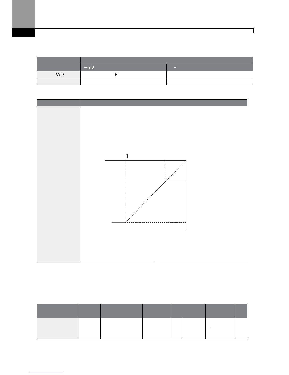
Learning Advanced Features
68
Rotational Directions for Different Voltage Inputs
Command / Voltage
Input
Input
voltage
0
––––
10V -10
––––
0V
FWD
For
ward
Reverse
REV Reverse
Forward
-10–10V Voltage Input Setting Details
Code
Description
In.12 V1 - volt x1
In.13 V1-Perc y1
In.14 V1-Volt x2
In.15 V1- Perc y2
Sets the gradient level and off
set value of the output frequency
in relation to
the input voltage. These codes are displayed only when In.06 is set to 1
(bipolar).
As an example, if the minimum input voltage (at V1) is set to -2 (V) with 10%
output ratio, and the maximum voltage is set to -8 (V) with 80% output ratio
respectively, the output frequency will vary within the range of 6 - 48 Hz.
[In.12 V1-volt X1 (min. volts), In.13 V1 Perc y1 (min. % speed)]
[In.14 V1 volt x2 (max. volts), In.15 V1 Perc y (max. % speed)]
For details about the 0–+10V analog inputs, refer to the code descriptions In.08
V1 volt x1–In.11 V1 Perc y2 on page 65.
4.1.3.3 Setting a Reference Frequency using Input Current (I2)
You can set and modify a frequency reference using input current at the I2 terminal after selecting
current input at SW 2 (Switch 2). Set the Frq (Frequency reference source) code in the Operation
group to 5 (I2) and apply 4–20mA input current to I2.
Group Code Name LCD Display
Parameter
Setting
Setting
Range
Unit
Operation Frq
Frequency
reference
source
Freq Ref
Src
5 I2
0–12
-
In.14 In.12
In.13
-8V -2V
6Hz
48Hz
In.15
V1 input
Frequency reference

Learning Advanced Features
69
Group Code Name LCD Display
Parameter
Setting
Setting
Range
Unit
In
01
Frequency at
maximum analog
input
Freq at
100%
60.00
0–
Maximum
Frequency
Hz
50
I2 input monitor
I2 Monitor 0.00
0.00–24.00
mA
52
I2
input filter time
constant
I2 Filter 10
0–10000
ms
53
I2 minimum
i
nput
current
I2 Curr x1 4.00
0.00–20.00
mA
54
I2 output at
minimum c
urrent
(%)
I2 Perc y1 0.00
0–100
%
55
I2 maximum
input current
I2 Curr x2 20.00
0.00–24.00
mA
56
I2 output at
maximum
current (%)
I2 Perc y2 100.00
0.00
–
100.00
%
61
I2 rotation
direction options
I2 Inverting 0 No
0–1
-
62
I2
Quantizing
level
I2
Quantizing
0.04
0*, 0.04–
10.00
%
* Quantizing is disabled if ‘0’ is selected.
Input Current (I2) Setting Details
Code
Description
In.01 Freq at 100%
Configures the
frequency reference
for operation
at
the maximum current
(when In.56 is set to 100%).
•
If In.01 is set to 60.00Hz, and default settings are used for In.53–56, 20mA
input current (max) to I2 will produce a frequency reference of 60.00Hz.
•
If In.56 is set to 50.00 (%), and default settings are used for In.01 (60Hz)
and In.53–55, 20mA input current (max) to I2 will produce a frequency
reference of 30.00Hz (50% of 60Hz).
In.50 I2 Monitor
Used to monitor
input
current at I2.
In.52 I2 Filter
Configures the time for the operation frequency to reach 63% of target
frequency based on the input current at I2.
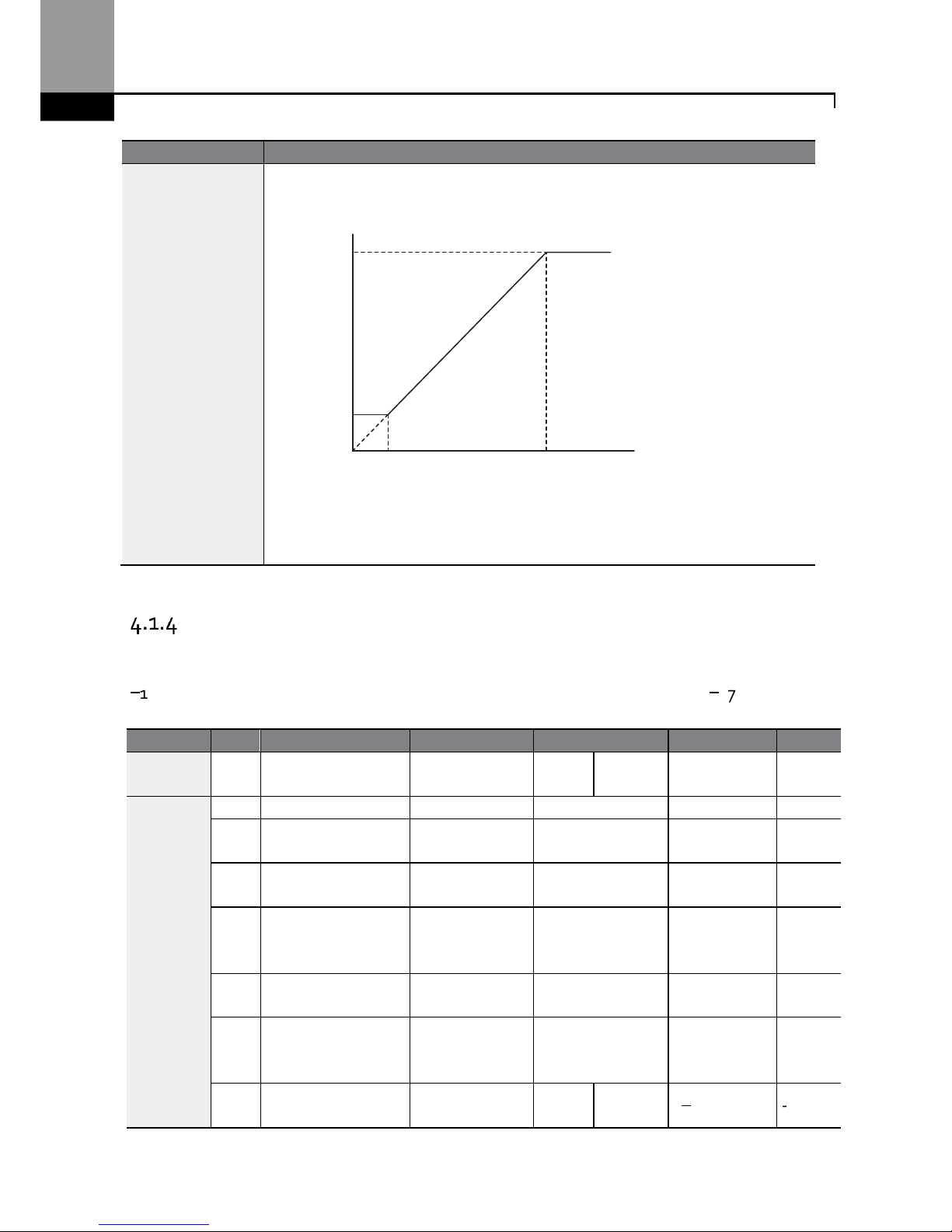
Learning Advanced Features
70
Code
Description
In.53 I2 Curr x1
In.54 I2 Perc y1
In.55 I2 Curr x2
In.56 I2 Perc y2
Configures the gradient level and off
set value of the output frequency.
[Gradient and off-set configuration based on output frequency]
[In.53 I2 Curr x1 (min. current), In.54 I2 Perc y1 (min. % speed)]
[In.55 I2 Curr x2 (max. current), In.56 i2 Perc y2 (max. % speed)]
Setting a Frequency Reference with Input Voltage (Terminal I2)
Set and modify a frequency reference using input voltage at I2 (V2) terminal by setting SW2 (switch
2) to V2. Set the Frq (Frequency reference source) code in the Operation group to 4 (V2) and apply
0–12V input voltage to I2 (=V2, Analog current/voltage input terminal). Codes In.35–47 will only be
displayed when I2 is set to receive voltage input (Frq code parameter is set to 4).
Group
Code
Name
LCD Display
Parameter Setting
Setting R
ange
Unit
Operation Frq
Frequency
reference source
Freq Ref Src 4 V2 0–12 -
In
35 V2
input display
V2 Monitor
0.00 0.00–12.00
V
37
V2
input filter time
constant
V2 Filter 10 0–10000 ms
38
Mini
mum V2 i
nput
voltage
V2 Volt x1 0.00 0.00–10.00 V
39
Out
put% at
minimum V2
voltage
V2 Perc y1 0.00 0.00–100.00 %
40
Maximum
V2 input
voltage
V2 Volt x2 10.00 0.00–10.00 V
41
O
utput% at
maximum V2
voltage
V2 Perc y2 100.00 0.00–100.00 %
46
Invert
V2
rotational
direction
V2 Inverting 0 No
0–1
-
I2
In.55
In.53
In.54
In.56
Frequency Reference
input
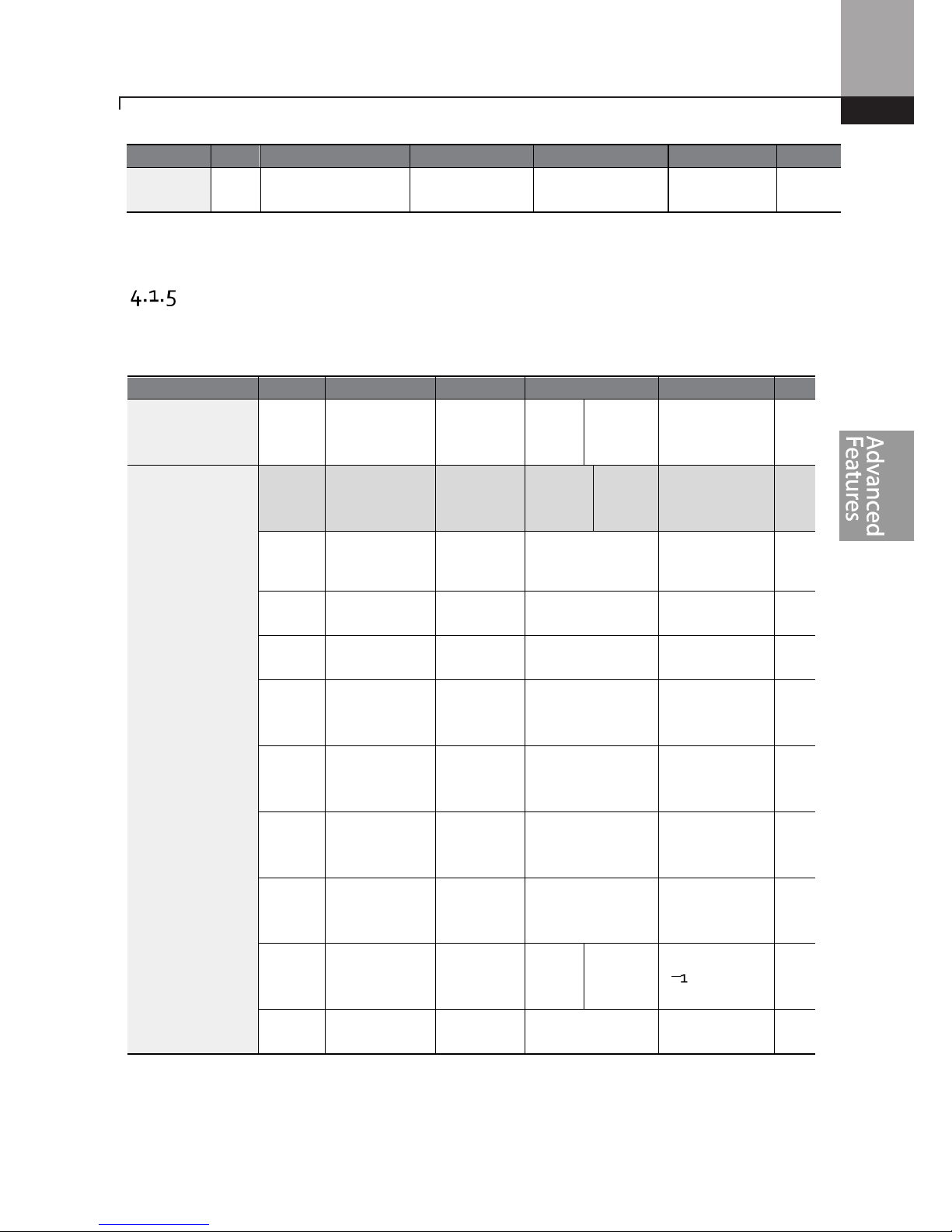
Learning Advanced Features
71
Group
Code
Name
LCD Display
Parameter Setting
Setting R
ange
Unit
47 V2 quantizing level V2 Quantizing 0.04
0
.00
*, 0.04
–
10.00
%
* Quantizing is disabled if ‘0’ is selected.
Setting a Frequency with TI Pulse Input
Set a frequency reference by setting the Frq (Frequency reference source) code in Operation group
to 12 (Pulse). When using the Standard I/O board, set parameter In.69 (P5 Define) to 54 (TI) and
provide a 0–32.00kHz pulse frequency to P5.
Group
Code
Name
LCD Display
Parameter Setting
Setting Range
Unit
Operation Frq
Frequency
reference
source
Freq Ref
Src
12 Pulse 0–12 -
In
69
P5 terminal
function
setting
P5 Define 54 TI 0-54 -
01
Frequency at
maximum
analog input
Freq at
100%
60.00
0.00
–
Maximum
frequen
cy
Hz
91
Pulse input
display
Pulse
Monitor
0.00 0.00–50.00 kHz
92
TI input filter
time constant
TI Filter 10 0–9999 ms
93
TI input
minimum
pulse
TI Pls x1 0.00 0.00–32.00 kHz
94
Output% at
TI
minimum
pulse
TI Perc y1 0.00 0.00–100.00 %
95
TI Inp
ut
maximum
pulse
TI Pls x2 32.00 0.00–32.00 kHz
96
Output% at TI
maximum
pulse
TI Perc y2 100.00 0.00–100.00 %
97
Invert TI
direction of
rotation
TI Inverting 0 No
0–1
-
98
TI q
uantizing
level
TI
Quantizing
0.04
0.00*, 0.04
–
10.00
%
* Data shaded in grey applies to the Standard I/O board only.
*Quantizing is disabled if ‘0’ is selected.
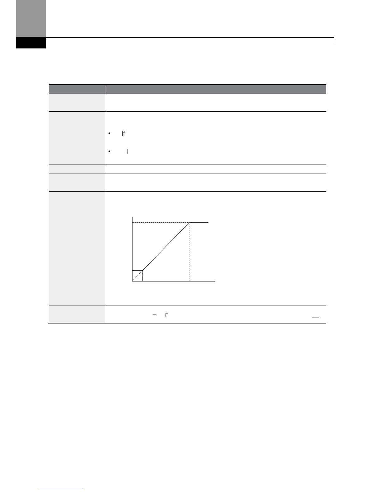
Learning Advanced Features
72
TI Pulse Input Setting Details
Code
Description
In.69 P5 Define
For Standard I/O,
Pulse input TI and Multi
-
function terminal P5 sh
are the sam
e
terminal. Set the In.69 (P5 Define) to 54(TI).
In.01 Freq at 100%
Configures the
frequency reference
at the m
aximum
pulse input
. The
frequency reference is based on 100% of the value set with In.96.
•
If In.01 is set to 60.00 and codes In.93–96 are set at default, 32kHz input to
TI yields a frequency reference of 60.00Hz.
•
If In.96 is set to 50.00 and codes In.01, In.93–95 are set at default, 32kHz
input to the TI terminal yields a frequency reference of 30.00Hz.
In.
91 Pulse Monitor
Displays the pulse
frequency supplied at
TI.
In.92 TI Filter
Sets the time for the pulse input at TI to reach 63% of its nominal frequency
(when the pulse frequency is supplied in multiple steps).
In.93 TI Pls x1
In.94 TI Perc y1
In.95 TI Pls x2
In.96 TI Perc y2
Configure
s the
gradient level
and
offset
values
for the output frequency
.
[In.93 TI Pls x1 (min. pulse freq.), In.94 TI Perc y1 (min. % speed)]
In.95 TI Pls x2 (max. pulse freq.), In.96 TI Perc y2 (max. % speed)]
In.97 TI Inverting
–
In.98 TI Quantizing
Identical to In.16–17 (refer to In.16 V1 Inverting/In.17.V1 Quantizing on page 65).
In.96
In.94
In.93 In.95
TI
Frequency reference
input
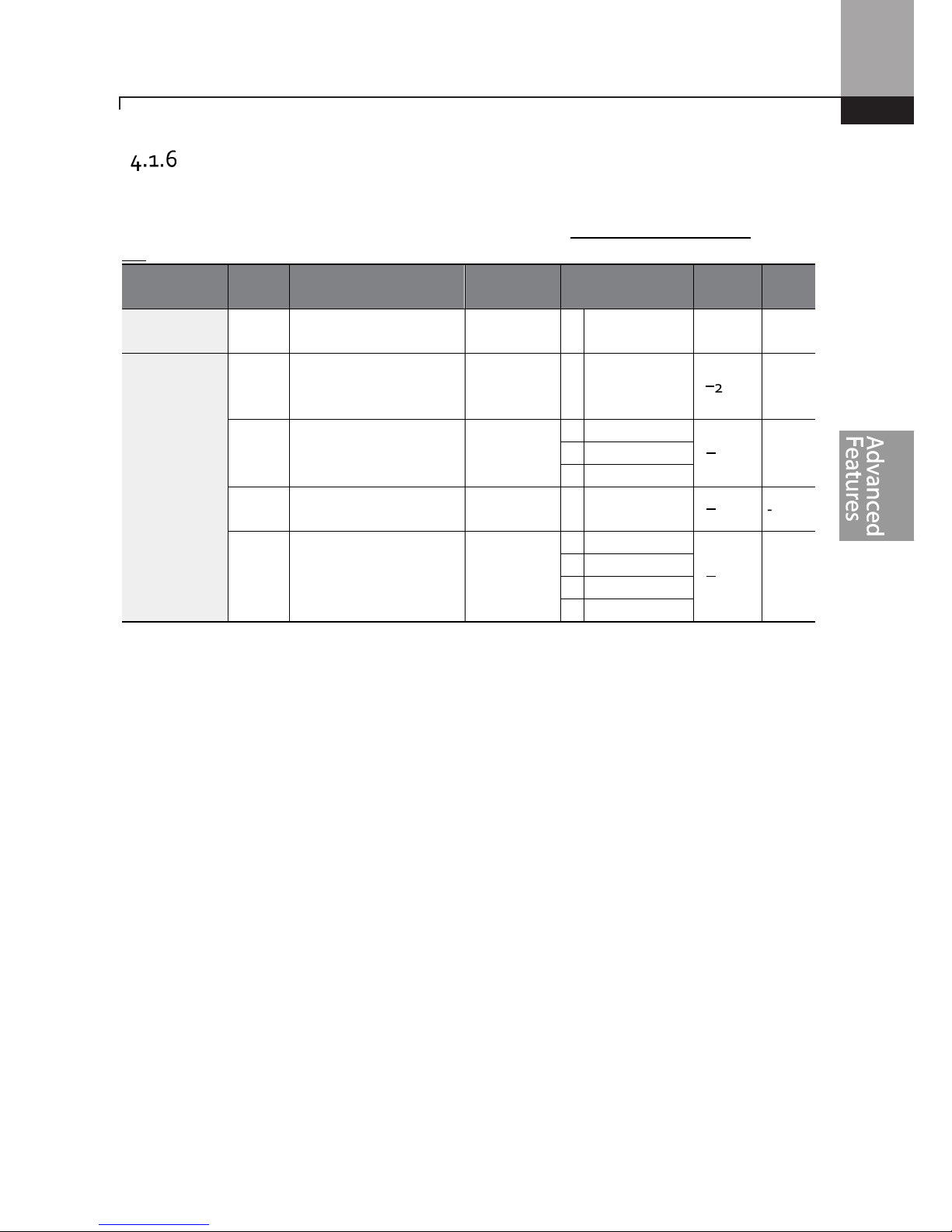
Learning Advanced Features
73
Setting a Frequency Reference via RS-485 Communication
Control the inverter with advanced controllers such as PLC’s or PC’s via RS-485 communication. Set
the Frq (Frequency reference source) code in the Operation group to 6 (Int 485) and use the RS-485
signal input terminals (S+/S-/SG) for communication. Refer to 7 RS-485 Communication F on page
231.
Group Code Name LCD Display Parameter Setting
Setting
Range
Unit
Operation Frq
Frequency reference
source
Freq Ref Src 6 Int 485 0–12 -
In
01
Inverter ID
Integrated RS-485
communication
Int485 St ID - 1
1–250
-
02
Protocol
Integrated RS-485
communication
Int485 Proto
0 ModBus RTU
0–2
-
1 Reserved
2 LS Inv 485
03
I
ntegrated
communication speed
Int485
BaudR
3 9600 bps
0–7
-
04
Integrated
communication frame
configuration
Int485
Mode
0 D8/PN/S1
0–3
-
1 D8/PN/S2
2 D8/PE/S1
3 D8/P
O/S1
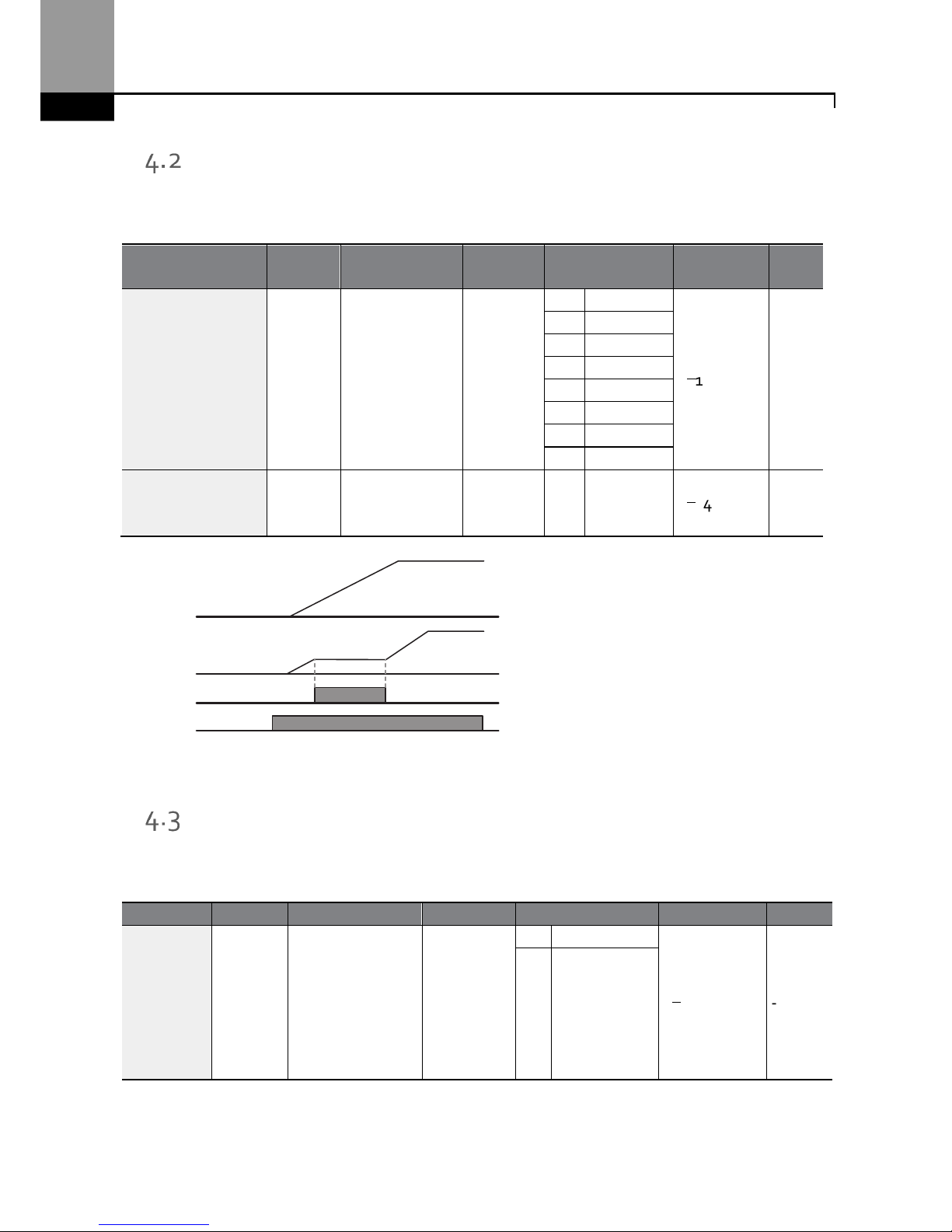
Learning Advanced Features
74
Frequency Hold by Analog Input
When the frequency reference is via an analog input, you can hold the operation frequency by
assigning a digital input as “analog hold”. The operation frequency will be fixed at the existing
analog input signal when the digital input terminal is activated.
Group Code Name
LCD
Display
Parameter Setting
Setting
Range
Unit
Operation Frq
Frequency
reference
source
Freq Ref
Src
0 Keypad
-1
0–12
-
1 Keypad
-2
2 V1
4 V2
5 I2
6 Int 485
8 Field
Bus
12 Pulse
In 65–69
Px terminal
configuration
Px
Define(Px
: P1–P5)
21
Analog
Hold
0–54
-
Changing the Displayed Units (Hz↔↔↔↔Rpm)
You can change the units used to display the operational speed of the inverter by setting Dr. 21
(Speed unit selection) to 0 (Hz) or 1 (Rpm). This function is available only with the LCD keypad.
Px
Frequency reference
Operating frequency
Run command
Group
Code
Name LCD Display
Parameter Setting
Setting Range
Unit
dr 21
Speed unit
selection
Hz/Rpm Sel
0 Hz Display
0–1
-
1
Rpm Display
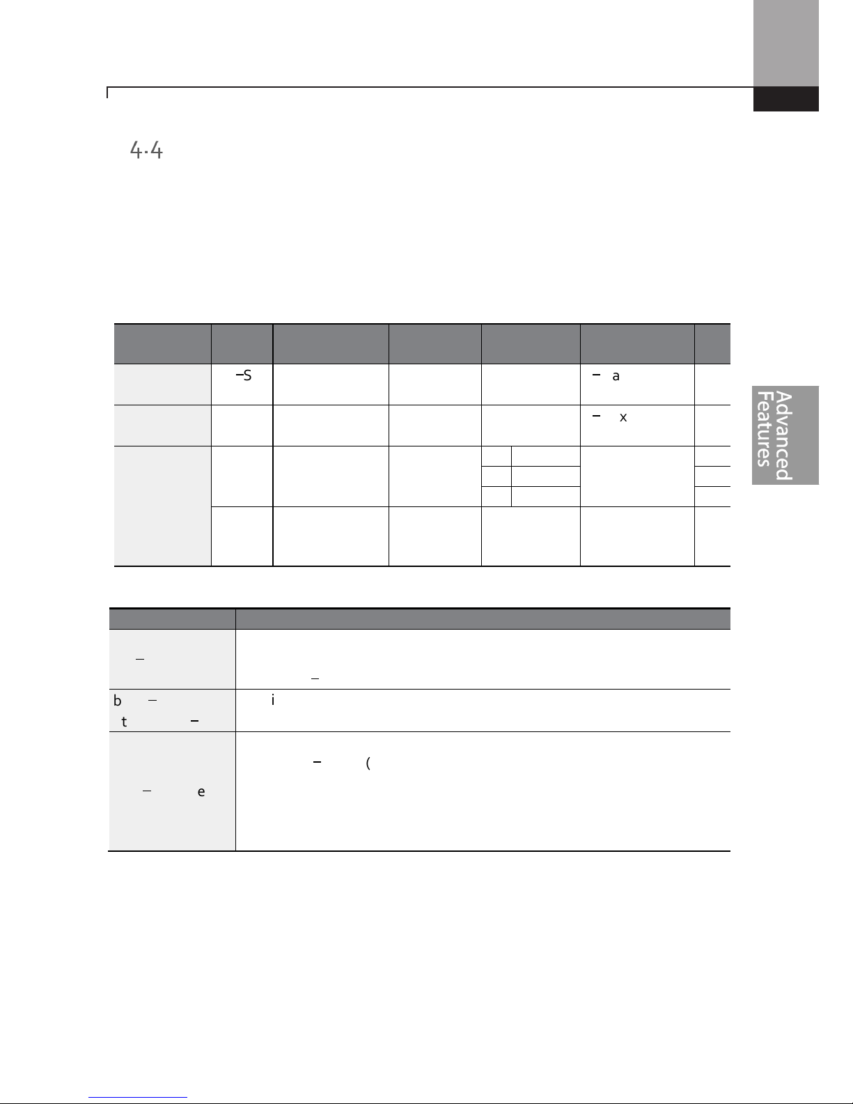
Learning Advanced Features
75
Setting Multi-step Frequency
Multi-step operations can be carried out by assigning different speeds (or frequencies) to the Px
terminals. Step 0 uses the frequency reference source set with the Frq code in the Operation group.
The digital input terminals can be programmed to provide fixed speed inputs (multi-step
frequencies). Parameters in the Input Group, In.65 through In.71 can be assigned 7 (Speed-L), 8
(Speed-M) and 9 (Speed-H). The step frequencies are set using parameters St1 through St3 (multistep frequencies 1 through 3) in the Operations Group. The digital inputs are recognized as a 3 bit
binary input. Additional speeds are set with parameters bA.53–56 (multi-step frequencies 4–7).
Group Code Name LCD Display
Parameter
Setting
Setting Range Unit
Operation
St1–St3
Multi-step
frequency 1–3
Step Freq
-
1–3
-
0–Maximum
frequency
Hz
bA 53–56
Multi-step
frequency 4–7
Step Freq
-
4–7
-
0–Maximum
frequency
Hz
In
65–71
Px terminal
configuration
Px Define
(Px: P1–P5)
7 Speed
-L
0–54
-
8 Speed
-M -
9 Speed
-H -
89
M
ulti-step
command delay
time
InCheck Time 1 1–5000 ms
Multi-step Frequency Setting Details
Code
Description
Operation group
St 1–St3
Step Freq - 1–3
Configure
multi
-
step frequency
1–3.
If an LCD keypad is in use, bA.50–52 is used instead of St1–St3 (multi-step
frequency 1–3).
bA.53–56
Step Freq - 4–7
Configure
multi
-
step
frequency
4–7.
In.65–69 Px Define
Choose the terminals
to setup
as multi
-
step input
s,
and then set the
relevant
codes (In.65–69) to 7(Speed-L), 8(Speed-M), or 9(Speed-H).
EX: Using terminals P3, P4 and P5 set to Speed-L, Speed-M and Speed-H
respectively, the following multi-step operation will be available.
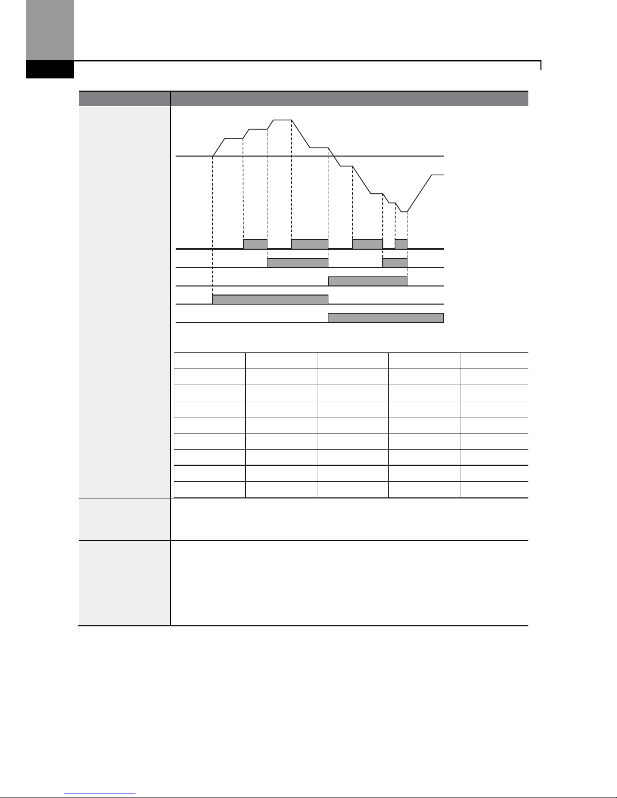
Learning Advanced Features
76
Code
Description
[An example of a multi-step operation]
Speed Fx/Rx P5 P4 P3
0
- - -
1
- -
2
-
-
3
-
4
- -
5
-
6
-
7
The parameters for the eight (8) speeds in the above example are:
Ref. Freq.=30Hz., St1=45Hz., St2=60Hz., St3=15Hz., bA.53=15Hz., bA.54=50Hz,
bA.55=55Hz., bA.56-60Hz.
In.89 InCheck Time
Set a
time interval for the inverter to check for
additional
terminal block
input
s
after receiving an input signal.
After adjusting In.89 to 100ms and an input signal is received at P5, the inverter
will search for inputs at other terminals for 100ms, before proceeding to
accelerate or decelerate based on P5’s configuration.
P3
P4
P5
RX
FX
Step 0
1
2
3
4
5
6
7
0
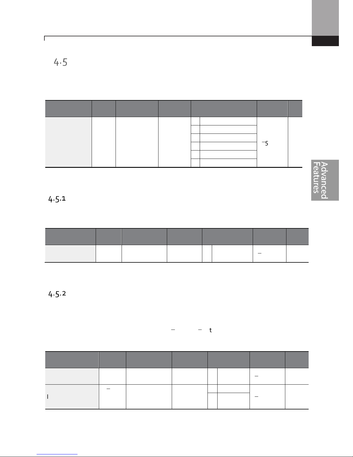
Learning Advanced Features
77
Command Source Configuration
The start and stop commands can come from various sources. Input devices available to select
include keypad, digital input terminals (Px), RS-485 communication and field bus adapter. If
UserSeqLink is selected, the common area can be linked with user sequence output and can be
used as command.
Group Code Name LCD Display Parameter Setting
Setting
Range
Unit
Operation
drv
Command
Source
Cmd
Source*
0 Keypad
0–5
-
1 Fx/Rx-1
2 Fx/Rx-2
3 Int 485
4 Field Bus
5 UserSeqLink
* Displayed under DRV-06 on the LCD keypad.
The Keypad as a Command Input Device
The keypad can be selected as the start/stop source for the inverter. This is configured by setting
the drv (command source) code to 0 (Keypad). Pressing the [RUN] key on the keypad starts the
inverter and the [STOP/RESET] key stops it.
group Code Name LCD Display Parameter Setting
Setting
Range
Unit
Operation
drv
Command
source
Cmd
Source*
0 KeyPad
0–5
-
* Displayed under DRV-06 on the LCD keypad.
Terminal Block as a Command Input Device (Fwd/Rev Run
Commands)
The digital input terminals can be selected as the start/stop command source. This is configured by
setting the drv (command source) code in the Operation group to 1(Fx/Rx). Select 2 terminals for
the forward and reverse operations, codes In.65–69 for P1–P5 to 1(Fx) and 2(Rx) respectively. This
application also enables both terminals to be turned on or off at the same time, constituting a stop
command that will cause the inverter to stop operation.
Group Code Name LCD Display
Parameter
Setting
Setting
Range
Unit
Operation
drv Command
source
Cmd
Source*
1 Fx/Rx-1
0–5
-
In
65–71
Px terminal
configuration
Px
Define(Px:
P1– P5)
1 Fx
0–54
-
2 Rx
* Displayed under DRV-06 on the LCD keypad.

Learning Advanced Features
78
Fwd/Rev Command by Multi-function Terminal – Setting Details
Code
Description
Operation group
drv– Cmd Source
Set to 1(Fx/Rx-1).
In.65–71 Px Define
Assign a terminal for f
orward
(Fx) operation.
Assign a terminal for reverse (Rx) operation.
Terminal Block as a Command Input Device (Run and Rotation
Direction Commands)
The digital inputs can be selected to operate as the start/stop source along with direction of
rotation. This is configured by setting the drv (command source) code in the Operation group to
2(Fx/Rx-2). Select 2 terminals for run and rotation direction commands, codes In.65–69 for P1–P5
to 1(Fx) and 2(Rx) respectively. This application uses the Fx input as a run command while the Rx
input determines the motor’s rotation direction.
Group Code Name LCD Display
Parameter
Setting
Setting
Range
Unit
Operation
Drv
Command
source
Cmd
Source*
2 Fx/Rx-2
0–5
-
In
65–69
Px terminal
configuration
Px Define
(Px: P1 – P5)
1 Fx
0–54
-
2 Rx
* Displayed under DRV-06 on the LCD keypad.
Run Command and Fwd/Rev Change Command Using Multi-function Terminal – Setting Details
Code
Description
Operation group
drv Cmd Source
Set to 2(Fx/Rx-2).
In.65–71 Px Define
Assign a terminal for run command (Fx).
Assign a terminal for changing rotation direction (Rx).
FX
RX
Frequency reference
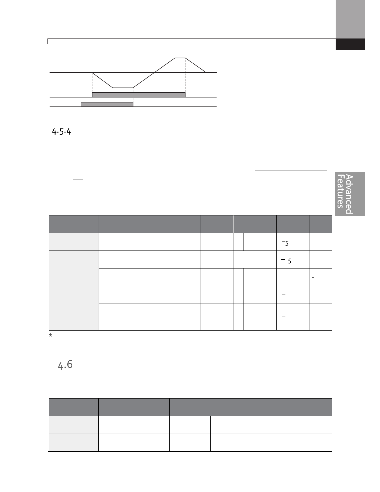
Learning Advanced Features
79
RS-485 Communication as a Command Input Device
Internal RS-485 communication can be selected as a command input device by setting the drv
(command source) code in the Operation group to 3(Int 485). This configuration uses advanced
controllers such as PCs or PLCs to control the inverter by transmitting and receiving signals via the
S+, S-, and Sg terminals at the terminal block. For more details, refer to 7 RS-485 Communication F
on page 231.
Group Code Name
LCD
Display
Parameter
Setting
Setting
Range
Unit
Operation
drv Command source
Cmd
Source*
3 Int 485
0–5
-
CM
01 Inverter ID
I
ntegrated
communication
Int485 St
ID
1
1–250
-
02 Protocol
I
ntegrated
communication
Int485
Proto
0 ModBus
RTU
0–2
-
03 I
ntegrated
communication speed
Int485
BaudR
3 9600 bps
0–7
-
04 I
ntegra
ted
communication frame
setup
Int485
Mode
0 D8 / PN /
S1
0–3
-
* Displayed under DRV-06 on the LCD keypad.
Local/Remote Mode Switching
Local/remote switching with the [ESC] key is used to override control and operate the system
manually using the keypad. The [ESC] key is programmable to many other functions. For other
functions, refer to 3.2.4 Configuring the [ESC] K on page 46.
Group Code Name
LCD
Display
Parameter Setting
Setting
Range
Unit
dr 90 [ESC
] key
functions
- 2 Local/Remote
0–2
-
Operation
drv Command
source
Cmd
Source*
1 Fx/Rx-1 0–5
-
FX
RX
Frequency

Learning Advanced Features
80
* Displayed under DRV-06 on the LCD keypad.
Local/Remote Mode Switching Setting Details
Code
Descripti
on
dr.90
[ESC] key functions
Set
dr.
90
to
2(Local/Remote)
to perform
local/remote
switch
ing
using
the [ESC]
key. Once the value is set, the inverter will automatically begin operating in r
emote
mode. Changing from local to remote will not alter any previously configured
parameter values and the operation of the inverter will not change.
Press the [ESC] key to switch the operation mode back to “local.” The SET light
will
flash, and the inverter will operate using the [RUN] key on the keypad. Press the
[ESC] key again to switch the operation mode back to “remote.” The SET light will
turn off and the inverter will operate according to the previous drv code
configuration.
N
ote
L
ocal/
R
emote
Operation
•
Full control of the inverter is available with the keypad during local operation.
•
During local operation, jog commands will only work if one of the P1–P5 multi-function terminals
(codes In.65–69) is set to 13(RUN Enable) and the relevant terminal is turned on.
•
During remote operation (remote operation), the inverter will operate according to the previously
set frequency reference source and the command received from the input device.
•
If Ad.10 (power-on run) is set to 0(No), the inverter will NOT operate on power-on even when the
following terminals are turned on:
- Fwd/Rev run (Fx/Rx) terminal
- Fwd/Rev jog terminal (Fwd jog/Rev Jog)
- Pre-Excitation terminal
To operate the inverter manually with the keypad, switch to local mode. Use caution when
switching back to remote operation mode as the inverter will stop operating. If Ad.10 (power-on
run) is set to 0(No), a command through the input terminals will work ONLY AFTER all the
terminals listed above have been turned off and then turned on again.
•
If the inverter has been reset to clear a fault during an operation, the inverter will switch to local
operation mode at power-on, and full control of the inverter will be with the keypad. The inverter
will stop operating when operation mode is switched from “local” to “remote”. In this case, a run
command through an input terminal will work ONLY AFTER all the input terminals have been
turned off.
Inverter Operation During Local/Remote Switching
Switching operation mode from “remote” to “local” while the inverter is running will cause the inverter
to stop operating. Switching operation mode from “local” to “remote” however, will cause the inverter
to operate based on the command source:
•
Analog commands via terminal input: the inverter will continue to run without interruption based
on the command at the terminal block. If a reverse operation (Rx) signal is ON at the terminal

Learning Advanced Features
81
block
at startup, the inverter will operate in the rev
erse direction even if it was running in the
forward direction in local operation mode before the reset.
•
Digital source commands: all command sources except terminal block command sources (which
are analog sources) are digital command sources that include the keypad, LCD keypad, and
communication sources. The inverter stops operation when switching to remote operation mode,
and then starts operation when the next command is given.
Use l
ocal/remote
operation
mode
switch
ing only when it is necessary.
Improper mode switching will
result in interruption of the inverter’s operation.
Forward or Reverse Run Prevention
The rotation direction of motors can be configured to prevent motors from running in either
direction. If Ad.09 is set to 2 Reverse Prev, pressing the [REV] key on the LCD keypad will cause the
motor to decelerate to 0Hz and stop. The inverter will remain on.
Group
Code
Name
LCD Display
Parameter Setting
Setting Range
Unit
Ad 09
Run prevention
options
Run Prevent
0 None
0–2 -
1 Forward Prev
2 Reverse Prev
Forward/Reverse Run Prevention Setting Details
Code
Description
Ad.09 Run Prevent
Choose a direction to
prevent
.
Setting
Description
0 None
Do not set run p
revention
.
1 Forward
Prev
Set f
orward
run pr
e
vention
.
2 Reverse Prev
Set r
everse
run prevention
.
Power-on Run
The power-on Run command can be set to start inverter operation after powering up. To enable
power-on run set the drv (command source) code to 1(Fx/Rx-1) or 2 (Fx/Rx-2) in the Operation
group. The digital input must be active (closed) during power up.
Group Code Name LCD Display
Parameter
Setting
Setting
Range
Unit
Operation drv
Command
source
Cmd
Source*
1, 2 Fx/Rx-1 or
Fx/Rx-2
0–5 -

Learning Advanced Features
82
Group Code Name LCD Display
Parameter
Setting
Setting
Range
Unit
Ad 10 Power-on run
Power
-
on
Run
1 Yes 0–1 -
* Displayed under DRV-06 on the LCD keypad.
Note
•
A fault may be triggered if the inverter starts operation while a motor’s load (fan-type load) is in
free-run state. To prevent this from happening, set bit4 to 1 in Cn. 71 (speed search options) of the
Control group. The inverter will perform a speed search at the beginning of the operation.
•
If the speed search is not enabled, the inverter will begin its operation in a normal V/F pattern and
accelerate the motor. If the inverter has been turned on without power-on run enabled, the
terminal block command must first be turned off, and then turned on again to begin the inverter’s
operation.
Use caution
when operating the inverter w
ith
Power
-
on Run
enabled
as
the motor
will begin rotating
when the inverter starts up.
Reset and Restart
Automatic restart after a fault reset can be setup with parameter Pr.08 set to 1 (Yes). The number of
reset attempts and the time delay between reset attempts are set with parameters Pr.09 and Pr.10.
The digital input for the run command (Fx/Rx-1) must remain closed to allow the inverter to run
after a successful reset. When a fault occurs, the inverter cuts off the output and the motor will freerun. Another fault may occur if the inverter begins its operation while motor load is in a free-run
state.
Group Code Name LCD Display Parameter Setting
Setting
Range
Unit
Operation
drv Command
source
Cmd
Source*
1 2 Fx/Rx-1 or
Fx/Rx-2
0–5
-
Pr
08 Reset restart
setup
RST Restart
1 Yes
0–1
09 No. of a
uto Retry
0 0–10

Learning Advanced Features
83
Group Code Name LCD Display Parameter Setting
Setting
Range
Unit
restart
Number
10 A
uto restart
delay time
Retry Delay
1.0
0–60
sec
* Displayed under DRV-06 in an LCD keypad.
Note
•
To prevent a repeat fault from occurring, set Cn.71 (speed search options) bit 2 equal to 1. The
inverter will perform a speed search at the beginning of the operation.
•
If the speed search is not enabled, the inverter will start its operation in a normal V/F pattern and
accelerate the motor.
•
With parameter Pr.08 set to 0 (No), when
the inverter is powered up with the run command made,
the inverter will not start. The run command (digital input) must be first turned off, and then
turned on again to begin the inverter’s operation.
Use caution
when operating the inverter w
ith Power
-
on Run enabled
as
the mo
tor will begin rotating
when the inverter starts up.
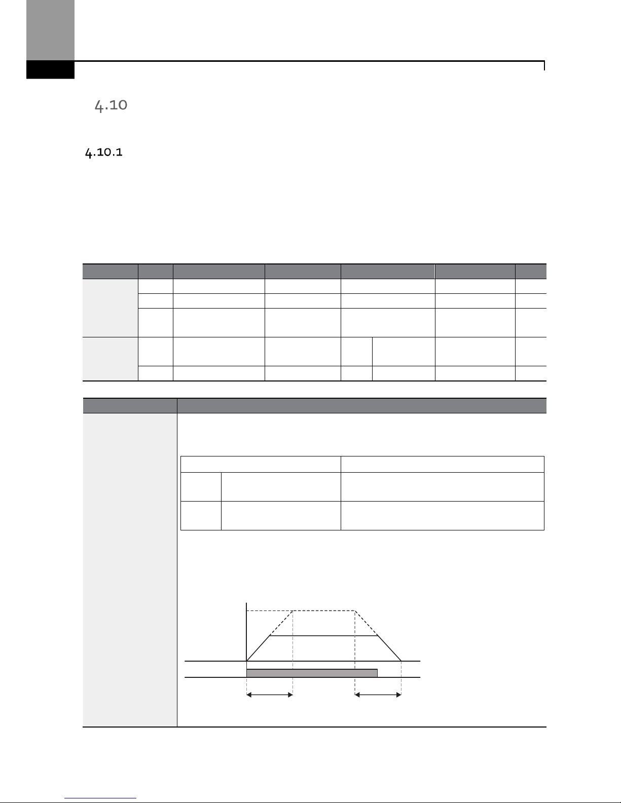
Learning Advanced Features
84
Setting Acceleration and Deceleration Times
Acc/Dec Time Based on Maximum Frequency
Acceleration time set at the ACC (Acceleration time) code in the Operation group (dr.03 in an LCD
keypad) refers to the time required for the inverter to reach the maximum frequency from a
stopped (0Hz) state. The Acc/Dec time values are based on maximum frequency when parameter
bA. 08 (Acc/Dec reference) in the Basic group is set to 0 (Max Freq, default setting). Likewise, the
value set at the dEC (deceleration time) code in the Operation group (dr.04 in an LCD keypad) refers
to the time required to return to a stopped state (0Hz) from the maximum frequency.
G
roup
Code
Name
LCD Display
Parameter
Setting
Setting Range
Unit
Operation
ACC Acceleration time
Acc Time
20.0 0.0–600.0
sec
dEC Deceleration time
Dec Time
30.0 0.0–600.0
sec
20
Maximum
frequency
Max Freq 60.00 40.00–400.00 Hz
bA
08
Acc/Dec reference
frequency
Ramp T Mode 0 Max Freq 0–1 -
09 Time scale
Time scale
1
0.1sec
0–2 -
Acc/Dec Time Based on Maximum Frequency – Setting Details
Code
Description
bA.08
Ramp T Mode
Set the parameter value to 0 (Max Freq) to setup Acc/Dec time based on
maximum frequency.
Configuration
Description
0 Max Freq
Set the Acc/Dec time based on maximum
frequency.
1 Delta Freq
Set the Acc/Dec time based on operati
ng
frequency.
If, for example, maximum frequency is 60.00Hz, the Acc/Dec times are set to 5
seconds, and the frequency reference for operation is set at 30Hz (half of 60Hz),
the time required to reach 30Hz therefore is 2.5 seconds (half of 5 seconds).
Max. Freq.
Frequency
Run cmd
Acc. time Dec. time
Learning Advanced Features
85
Code
Description
bA.09 Time scale
Use
the time scale for all time
-
related values.
It is pa
rticularly
useful when a more
accurate Acc/Dec times are required because of load characteristics, or when the
maximum time range needs to be extended.
Configuration
Description
0 0.01sec
Sets
0.01 second as the minimum unit.
1 0.1sec
Sets
0.1 second as the minimum unit.
2 1sec Sets
1 second as the minimum unit.
N
ote that the range of maximum
time value
s may change automatically when
the units are
change
d.
If for example, the acceleration time is set at 6000 seconds, a time scale change from 1 second to 0.01
second will result in a modified acceleration time of 60.00 seconds.
Acc/Dec Time Based on Operation Frequency
Acc/Dec times can be set based on the time required to reach the next step frequency from the
existing operation frequency. To set the Acc/Dec time values based on the existing operation
frequency, set bA. 08 (acc/dec reference) in the Basic group to 1 (Delta Freq).
Group
Code
Name
LCD Display
Parameter Setting
Setting Range
Unit
Operation
ACC Acceleration time
Acc Time
20.0
0.0–600.0
sec
dEC D
eceler
ation time
Dec Time
30.0
0.0–600.0
sec
bA 08 Acc/Dec reference
Ramp T Mode
1
Delta Freq
0–1 -
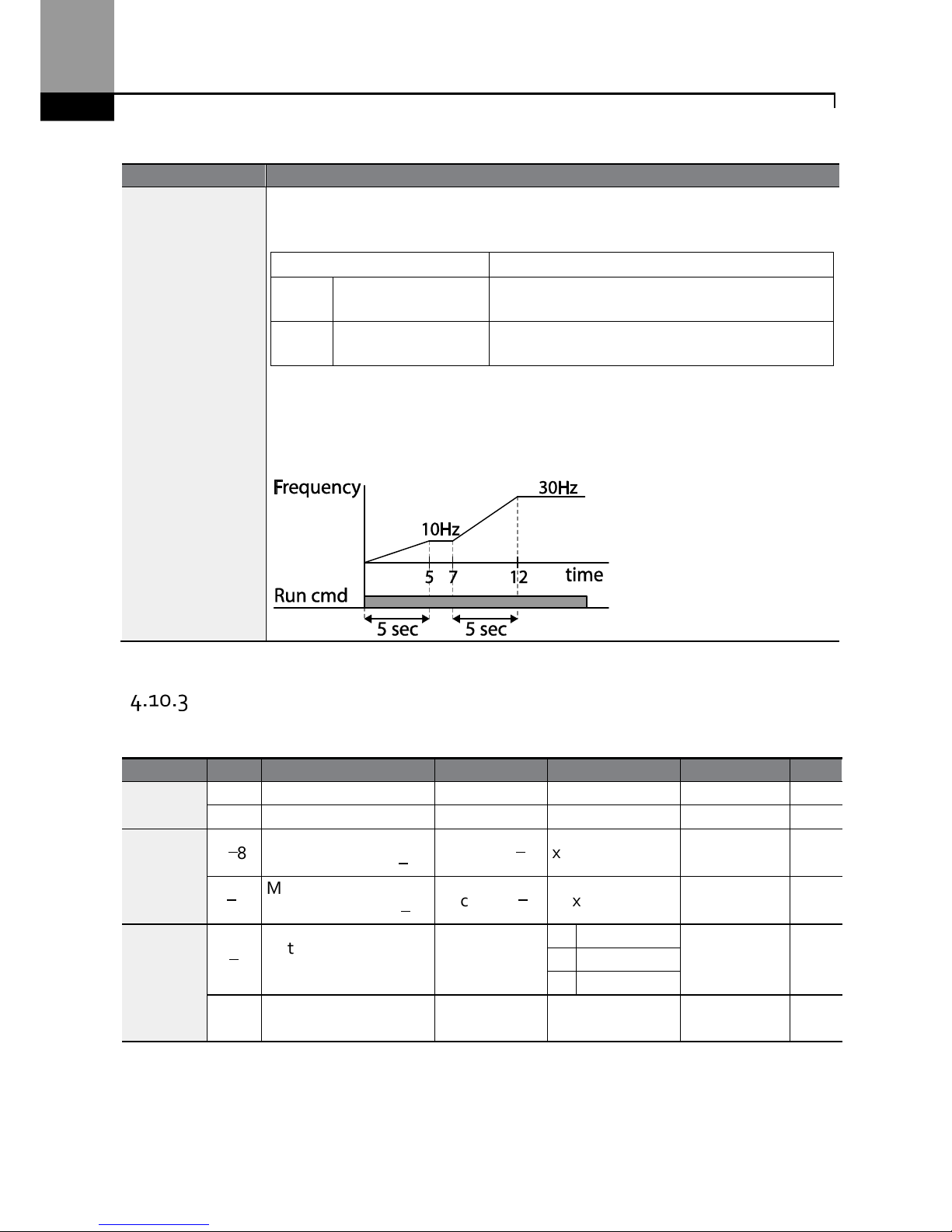
Learning Advanced Features
86
Acc/Dec Time Based on Operation Frequency – Setting Details
Code
Description
bA.08
Ramp T Mode
Set the parameter value to 1 (Delt
a Freq) to set Acc/Dec time
s based on
M
aximum
frequency.
Configuration
Description
0 Max Freq
Set the Acc/Dec time based on
M
aximum
frequency.
1 Delta Freq
Set the Acc/Dec time based on
O
peration
frequency.
If Acc/Dec times are set to 5 seconds, and multiple frequency references are used
in
the operation in 2 steps, at 10Hz and 30 Hz, each acceleration stage will take 5
seconds (refer to the graph below).
Multi-step Acc/Dec Time Configuration
Acc/Dec times can be configured via digital input terminals by setting the ACC (acceleration time)
and dEC (deceleration time) codes in the Operation group.
Group
Code
Name
LCD Display
Parameter Setting
Setting Range
Unit
Operation
ACC
Acceleration time
Acc Time
20.0
0.0–600.0
sec
dEC D
eceleration time
Dec Time
30.0 0.0–600.0
sec
bA
70–82
M
ulti-step
acceleration time1–7
Acc Time 1–7
x.xx 0.0–600.0 sec
71–83
M
ulti-step
deceleration time1–7
Dec Time 1–7
x.xx 0.0–600.0 sec
In
65–69
Px terminal
configuration
Px Define
(Px: P1–P5)
11 XCEL
-L
0–54 -
12 XCEL
-M
49 XCEL
-H
89
M
ulti-step command
delay time
In Check Time 1 1–5000 ms
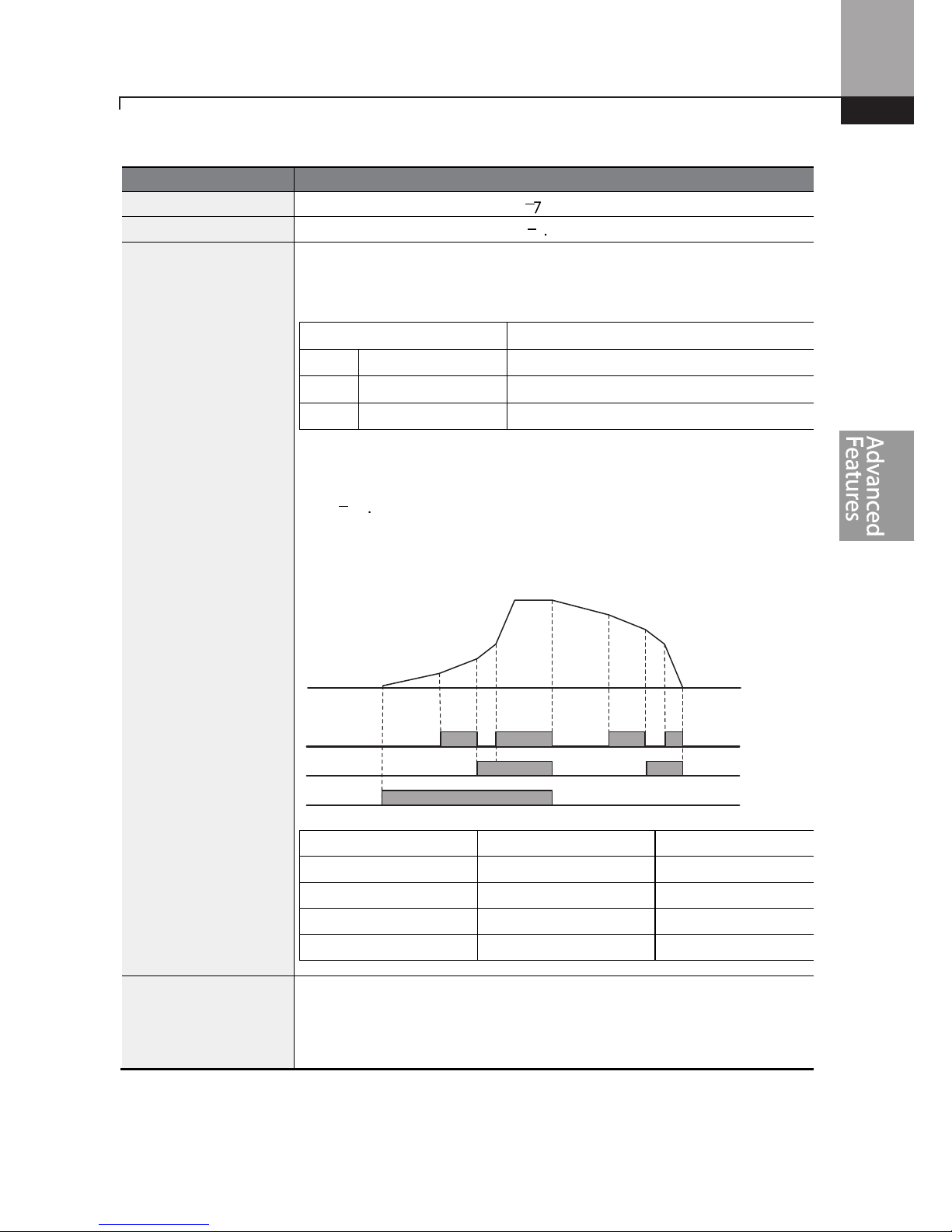
Learning Advanced Features
87
Acc/Dec Time Setup via Multi-function Terminals – Setting Details
Code
Description
bA. 70–82 Acc Time 1–7
Set multi-step acceleration time1–7.
bA.71–83 Dec Time 1–7
Set multi-step deceleration time1–7.
In.65–69
Px Define (P1–P5)
Choose and configure the terminals to use for multi-step Acc/Dec time
inputs.
Config
uration
Description
11 XCEL
-L
Acc/Dec command
-L
12 XCEL
-M
Acc/Dec command
-M
49 XCEL
-H
Acc/Dec command
-H
Acc/Dec commands are recognized as binary code inputs and will control
the acceleration and deceleration based on parameter values set with
bA.70–bA.83.
If, for example, the P4 and P5 terminals are set as XCEL-L and XCEL
respectively, the following operation will be available.
Acc/Dec time
P5 P4
0 - -
1 -
2
-
3
In.89 In Check Time
Set the time for the inverter to check for other terminal block inputs. If
In.89 is set to 100ms and a signal is supplied to the P4
terminal, the inverter
searches for other inputs over the next 100ms. When the time expires, the
Acc/Dec time will be set based on the input received at P4.
P4
P5
Frequency
Acc0
Acc1
Acc2
Acc3 Dec0
Dec1
Dec2
Dec3
Run cmd

Learning Advanced Features
88
Configuring Acc/Dec Time Switch Frequency
You can switch between two different sets of Acc/Dec times (Acc/Dec gradients) by configuring the
switch frequency without configuring the multi-function terminals.
Group
Code
Name
LCD Display
Para
meter Setting
Setting Range
Unit
Operation
ACC Acceleration time
Acc Time
10.0 0.0–600.0
sec
dEC Deceleration time Dec Time 10.0
0.0–600.0
sec
bA
70
M
ulti-step
acceleration time1
Acc Time-1 20.0
0.0–600.0
sec
71
M
ulti-step
deceleration time1
Dec Time-1 20.0
0.0–600.0
sec
bA 69
Acc/Dec switch
frequency
Xcel Change
Frq
30.00
0–Maximum
frequency
Hz
Acc/Dec Time Switch Frequency Setting Details
Code
Description
bA.69
Xcel Change Fr
When
the
Acc/Dec switch frequency (
bA.69
, Xcel Change Fr) is
set and the
inverter
operation is at or below the set frequency, it will use the accel and decel times set
in parameters bA.70 and 71. If the operation frequency is above the switch
frequency, it will use the accel and decal times set in parameters ACC and dEC
codes.
If you configure the P1–P5 multi-function input terminals for multi-step Acc/Dec
gradients (XCEL-L, XCEL-M, XCEL-H), the inverter will operate based on the
Acc/Dec inputs at the terminals instead of the Acc/Dec switch frequency
configurations.
Acc/Dec Pattern Configuration
Acc/Dec gradient level patterns can be configured to enhance and smooth the inverter’s
acceleration and deceleration curves. The linear pattern features a linear increase or decrease to the
output frequency, at a fixed rate. With an S-curve pattern, a smoother and more gradual increase or
decrease of output frequency is performed. S-curve gradient level can be adjusted using codes Ad.
03–06 in the Advanced group.
Group
Code
Name
LCD Display
Parameter Setting
Setting Range
Unit
bA 08 Acc/Dec reference
Ramp T mode
0
Max Freq
0–1 -
bA.69
 Loading...