

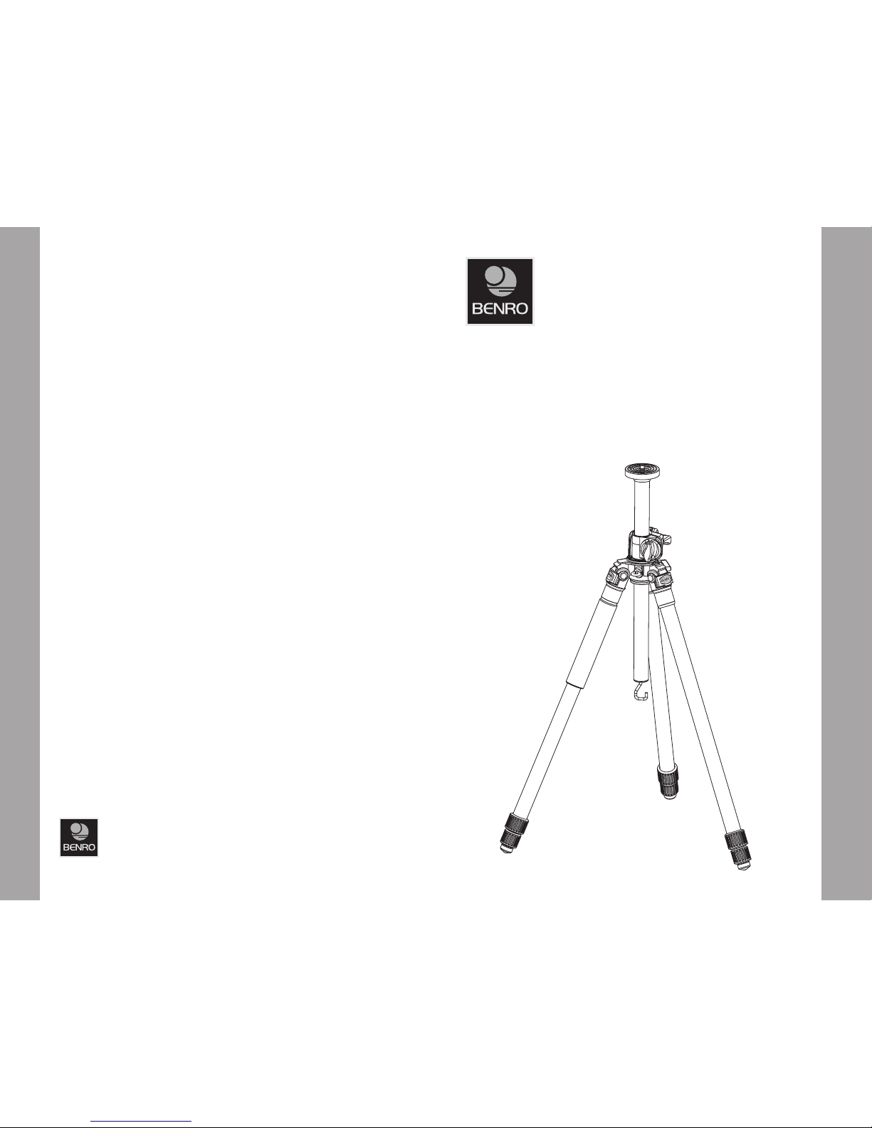
HVC-SERIES FLEXPOD TRIPODS
OPERATING INSTRUCTIONS
Thank you for making Benro your choice for professional photographic
equipment. Your Benro gear is manufactured to provide years of
dependable ser vice. In order to obtain optimum satisfaction and
performance, we suggest that you carefully read these instructions.
USER NOTICE
Do not exceed the maximum specified •
load capacity (see specific ations on the
package label or visit www.benro.com).
Always ensure that Leg and Head Lock s •
are tightly engaged before mounting any
gear on your Tripod.
Do not use any Tripod below temperatures •
of −4°F or above +158°F (−20°C / +70°C).
Always clean and dry any Tripod after it •
has been exposed to wet, dust y, sandy
or salty conditions. Your Tripod is not
recommended for use in salt water. If
required, clean tripod using a mild soap
solution applied with a soft cloth, rinse
with fresh water and dry with sof t towel.
Remove any dust, dirt or sand from all Leg
Locks, Leg Sections and all moving par ts.
Do not leave any Tripod in the sun •
for prolonged periods and avoid high
temperature exposure.
Avoid leaving any Tripod or Monopod •
unattended in areas where people could
trip over the gear and get hurt.
Remove camera, lens, and all gear from •
any tripod when transporting.
For your safety, don’t let your Benro •
gear come in contact with any electrical
power source.
OPERATING INSTRUCTIONS AND USER NOTICE
8 Westchester Plaza
Elmsford, NY 10523
T 914.347.3300
F 914.347.3309
info@Benro.com
Benro.com
Specifications and design ar e subject
to change without notice.
A. Vertical Column Positioning (FIGURE 6)
See instructions above for Raising and
Lowering the Center Column.
B. Angular and Horizontal Column
Positioning (FIGURES 7 & 8)
Unlock the Center Column by turning the
Center Column Locking Knob counterclockwise. Then raise the Center C olumn
up until it clears the main casting. Unlock
the Horizontal Locking Knob by turning
counter-clockwise and position the
Column at the desired angle. Turn both
the Center Column and Horizontal Locking
Knobs clockwise to lock.
C. Center Column Panning and Rotation
(FIGURE 9)
Unlock the center column Pan Lock Knob
to Pan the entire Flex Column assembly
and/or to rotate the Center Column. Re-lock
when the desired position is reached.
NOTE: In the horizontal or an angular
Column position, it is recommended that
you carefully hang your camera bag or other
weight on the Center Column Weight Hook at
the opposite end of the mounted equipment
or camera. This weight will act as a counter
balance to help stabilize the Tripod and
reduce the chance of it falling over because
of unequal weight distribution.
Reversible Center Column (FIGURE 10)
In addition to the Flex movement, your Tripod
has the ability to reverse the Center Column.
To reverse the Center Column, loosen the
Center Column Locking Knob and pull the
Center Column out. Insert the Center Column
through the bottom with the Mounting
Plate upside-down and retighten the Center
Column Locking Knob securely.
NOTE: Do not reverse the C enter Column
when a camera or equipment is mounted.
Interchangeable Spiked and Rubber Feet
(select models) (MAIN FIGURE)
Most Benro tripods include interchangeable
Stainless Steel Spiked or Rubber Feet. They
provide the right contact depending on the
surface or terrain that the tripod will be used
in. To remove the Rubber Feet simply unscrew
each Rubber Foot counter-clockwise and
replace with the provided Spiked Feet. Tighten
the Spiked Feet using the included Wrench.
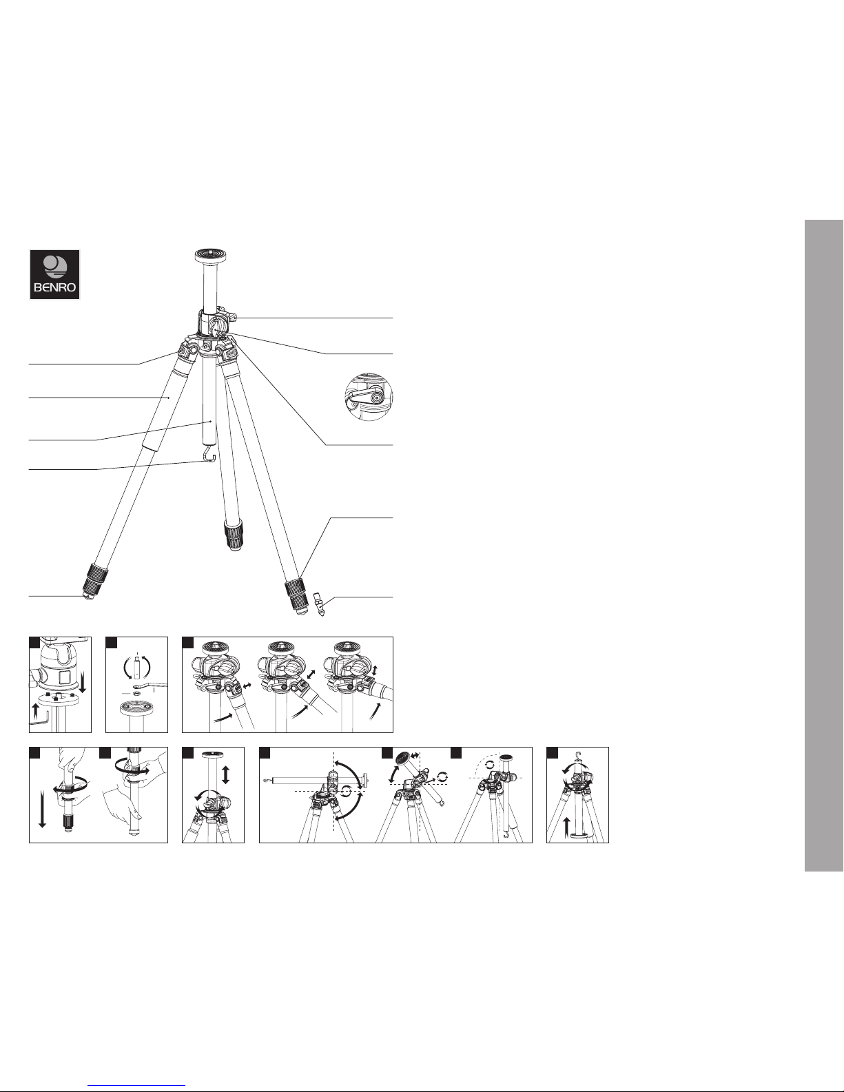
SETUP
Head Mounting (FIGURES 1 & 2)
If your Tripod did not come with a Head,
select one of the fine Benro Ballheads or
Panheads that match your size Tripod and
install by screwing the Head clockwise
onto the 3/8" Mounting Thread of the Top
Plate. Once it is hand tight, secure by fully
tightening the Head Locking Screw(s) from
below with the included Allen Key.
Most Heads have a 3/8” b ase mount so
your Benro Tripod is shipped with the 3/8
Mounting Thread exposed, but if the Head
you choose uses a 1/4 –20 you can attach
it by simply reversing the Mounting Screw.
To do this turn the Locking Nut counterclockwise (using the supplied Wrench) until
it becomes loos e, and unscrew the Mounting
Screw until it can be completely removed.
Reverse the Screw, so that the threads are in
position and screw it back into place, secure
with the Locking Nut using the Wrench.
NOTE: Allow enough of the screw threads to
be available for maximum security when the
Tripod Head is mounted onto the Tripod. It’s
recommended that at least 5 to 6 threa ds be
exposed before locking the Mounting Screw
in place.
OPERAT ION
Before using your Tripod, adjust each
Leg Section to the desired height and
Leg Angle Setting.
Make sure that the Tripod is firmly resting
on a level surface and mount your camera
securely on the Tripod Head. Always engage
any safety locks on the Tripod Head to
prevent any accidental dismounting.
FOR BEST RESULTS: Do not raise the Tripod
higher than necessar y and extend the largest
diameter Leg Sections first. Only extend the
Center Column if required to reach maximum
height or to fine-tune the vertical position.
FOR EXTR A STABILITY: Carefully hang your
camera bag or other weight on the Weight
Hook at the bottom of the Center C olumn.
NOTE: Never carry your Tripod with camera
gear attached.
Leg Angle Adjustment (FIGURE 3)
To accommodate uneven terrain, awkward
shooting situations or for low angle shooting,
your Benro Tripod includes a 3-position Leg
Angle Adjustment Sliding Lock. Each Leg can
be adjusted by pulling the Leg Angle Lock
out and selecting one of the three positions.
Please make sure that the Leg Angle Lock is
securely pushed back into the lock position
after you have selected the desired Le g Angle.
Leg Section Adjustment (FIGURES 4 & 5)
Each Leg section can be adjusted to the
desired length by turning the leg lock grip
1/2 turn (180°) clockwise until the Leg is
free to slide in or out. Once the desired
length is achieved, turn the Leg Lock Grip
counter-clockwise until the Leg Section is
securely locked. Repeat this step for each
Leg and each Section until the Tripod is set
to the desired height.
NOTE: To prevent any accidental damage
to your gear, always remove any mounted
equipment (camera, etc.) from the Tripod
before adjusting the Leg Sections.
Raising and Lowering the Center Column
(FIGURE 6)
To raise or lower the Center Column, turn
the Center Column Locking Knob clockwise
and set the Column to the desired position.
While holding the Column in position, turn
the Center Column Locking Knob counterclockwise to secure the Column in place.
Don’t over-tighten the Center Column Lock,
as this could damage the threads.
NOTE: Take special care when raising or
lowering the Center Column, if a camera or
equipment is mounted on the Tripod. Never
loosen the Center Column Locking Knob
without holding the Center Column. Failure
to follow these instructions could result in
damaged equipment.
Multi-Position Flex Column
(FIGURES 6, 7, 8 & 9)
The Flex Column offers rapid and convenient
vertical, angular and horizontal Center
Column positioning. The Center Column
can be converted from a st andard vertical
orientation to a horizontal cross bar. In
the horizontal position, a mounted camera
can have a clear view straight up or down
(without the Tripod legs getting in the way),
to achieve challenging and creative angles.
The Flex column is ideal for flat artwor k,
close-up macro photography and fo r shoots
that require total flexibility in camera
position. When the column is returned to
the standard vertical orientation, it’s unique
design positions it back in the center of
the main casting ensuring perfect center of
gravity and balance.
Center Column
Locking Knob
Center Column
Pan Lock Lever
Horizontal
Locking Knob
Weight Hook
Leg Lock Grip
Closed Cell Foam Grip
Leg Angle Adjustment Lock
Rubber Foot
Reversible
Center Column
3
Unlock Lock
4 5
Locking
Nut
1/4-20 + 3/8
Mounting Screw
Wrench
2
6
90°
7 98
OPERATING INSTRUCTIONS
(continued on back page)
Interchangeable
Spiked Foot
(on select models)
10
1
 Loading...