


Specificati ons and design are subjec t
to change without notice.
Travel Flat Series Tripods
75 Virginia Road
North Whit e Plains, NY 10603
T 914.347.3300
F 914.347.3309
info@BenroUSA.com
BenroUSA.com
Operating Instructions
Thank you for making Benro your choice for professional photographic
equipment. Your Benro gear is manufactured to provide years of
dependable service. In order to obtain optimum satisfaction and
performance, we suggest that you carefully read these instructions.
SETUP
Head Mount ing FIGURES 1 & 2
If your Tripod did not come wit h a Head,
select one o f the fine Benro Ballheads or
Panheads that match your siz e Tripod an d
install by screwing t he Head clockwise onto
the 3/8" Mounting Threa d of the Top Plate.
OPERATION
Before using your Tripod, f irmly pull the
three Legs out until th ey stop and adjust
each Leg Secti on to the desired height.
Make sure that the Tripod is fir mly resting
on a level surface a nd mount your camera
securely on the Tripod H ead. Always
engage any safet y locks on the Tripod Head
to prevent any accidental dismounting.
FOR BEST RESULTS: Do not raise th e Tripod
higher than necess ary and extend the
largest diameter L eg Sections first. On ly
add the Center Column if re quired to reach
maximum height or to f ine-tune the vertical
position.
NOTE: Never carr y your Trip od with camera
gear attached.
Leg Section Adjustment
FIGURES 1 & 2
Each Leg sec tion can be adjusted to the
desired length by tu rning the leg lock grip
1/2 turn (180°) clockwise until the Leg is f ree
to slide in or out. Once th e desired length is
achieved, turn the Le g Lock Grip counterclockwise unt il the Leg Section is securely
locked. Repeat t his step for each Leg and
each Section u ntil the Tripo d is set to the
desired height.
NOTE: To prevent any accidental damag e
to your gear, always remove any mounted
equipment (camera , etc.) from the Tripod
before adjusting the Leg Sections .
Center Colum n
FIGU RES 3, 4 & 5
The Center Column can b e attached when
additional heig ht is required. Simply screw
the Center Column onto the Tripod Top
Plate. The Center Column has t wo sections
and can be exte nded using the Lock Grip
adjustments simi lar to the Lock Grips on the
Leg Sections.
NOTE: Take special care when ra ising or
lowering the Center Colum n, if a camera or
equipment is mounte d on the Trip od. Never
loosen the Center Colu mn Locking Knob
without holding the Center Column. Failure
to follow these instr uctions could result in
damaged equipment.
Intercha ngeable Spiked and Rub ber Feet
(select mo dels)
MAIN FIGURE
Most Benro trip ods include interchangeable
Stainless Steel Spiked o r Rubber Feet.
They provide the right contact depending
on the surface or te rrain that the tripod
will be used in. To remove the Rubb er Feet
simply unscrew each Ru bber Foot counterclockwise an d replace with the provided
Spiked Feet. Tig hten the Spiked Feet using
the included Wrench.
USER NOTICE
• Do not exceed the ma ximum specified
load capacit y (see specifications at
www.BenroUSA.com).
• Always ensure that Leg and H ead Locks
are tightly engage d before mounting any
gear on your Tripod.
• Always clean and dr y any Tripod af ter it
has been expo sed to wet, dusty, sandy
or salty condi tions. Your Tripod is n ot
recommended fo r use in salt water. If
required, clean tripod using a mild soap
solution applie d with a soft cloth, rinse
with fresh water and dr y with soft towel.
Remove any dust, dir t or sand from all Leg
Locks, Leg Se ctions and all moving parts .
• Do not leave any Tripod in the sun for
prolonged p eriods and avoid high
temperature exposure.
• Avoid leaving any Tripod or Monop od
unattended in a reas where people could
trip over the gear and ge t hurt.
• Remove camera, l ens, and all gear from
any tripod when transporting.
• For your safety, don’t l et your Benro
gear come in contac t with any electrical
power source.
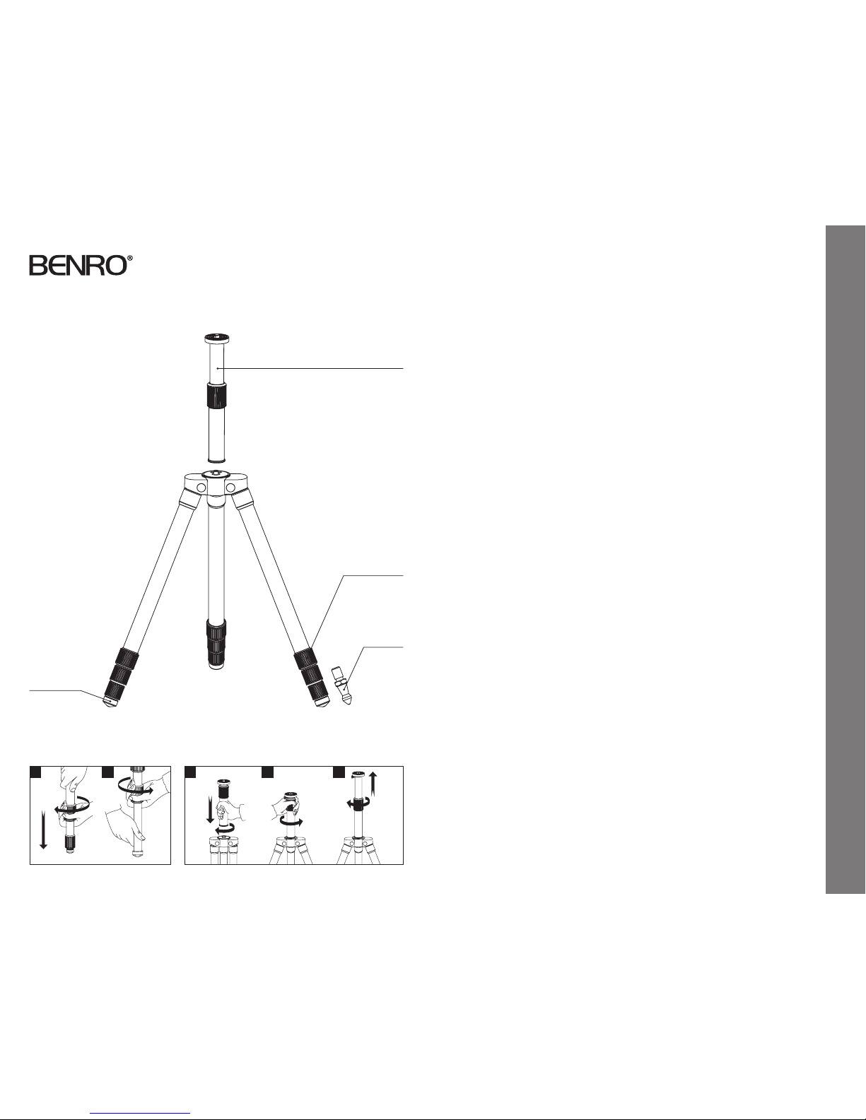
Two-Piece Exten dable
Center Column
Leg Lock Grip
Rubber Foot
3
Unlock Lock
1 2
4 5
Operating Instructions & User Notice
Interchangeable
Spiked Fo ot
(on select models)
 Loading...