

BENRO Travel Angel Operating Instructions Manual
Travel Angel Series Tripods (Including Transfunctional Models)
75 Virginia Road
North Whit e Plains, NY 10603
T 914.347.3300
F 914.347.3309
info@BenroUSA.com
BenroUSA.com
Intercha ngeable Spiked and Ru bber Feet
(select mo dels)
MAIN FIGURE
Most Benro trip ods include interchangeable
Stainless Steel Spiked o r Rubber Feet.
They provide the right contact depending
on the surface or te rrain that the tripod
will be used in. To remove the Rubb er Feet
simply unscrew each Ru bber Foot counterclockwise an d replace with the provided
Spiked Feet. Tig hten the Spiked Feet using
the included Wrench.
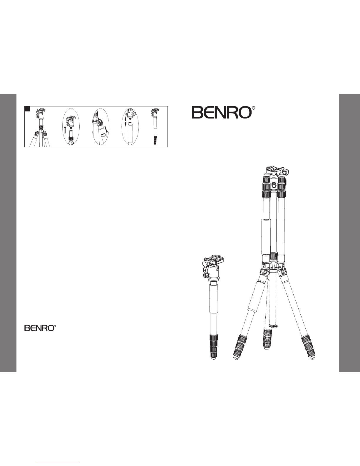
Transfunctio nal Feature – Convertin g to
a Monopod (se lect models)
FIGURE 9
To assemble as a monopod f irst unscrew
the Ballhead and Top Plate from the ce nter
column. Unscrew the Sing le tripod leg (the
one with the foam gri p). Screw the B allhead
and Top Plate onto the top of the Single Leg .
USER NOTICE
• Do not exceed the ma ximum specified
load capacit y (see specifications at
www.BenroUSA.com).
• Always ensure that Leg and H ead Locks
are tightly engage d before mounting any
gear on your Tripod.
• Always clean and dr y any Tripod af ter it
has been expo sed to wet, dusty, sandy
or salty condi tions. Your Tripod is n ot
recommended fo r use in salt water. If
required, clean tripod using a mild soap
solution applie d with a soft cloth, rinse
with fresh water and dr y with soft towel.
Remove any dust, dir t or sand from all Leg
Locks, Leg Se ctions and all moving part s.
• Do not leave any Tripod in the sun for
prolonged p eriods and avoid high
temperature exposure.
• Avoid leaving any Tripod or Monop od
unattended in a reas where people could
trip over the gear and ge t hurt.
• Remove camera, l ens, and all gear from
any tripod when transporting.
• For your safety, don’t l et your Benro
gear come in contac t with any electrical
power source.
Operating Instructions & User Notice
Operating Instructions
Thank you for making Benro your choice for professional photographic
equipment. Your Benro gear is manufactured to provide years of
dependable service. In order to obtain optimum satisfaction and
performance, we suggest that you carefully read these instructions.
Specificati ons and design are subjec t
to change without notice.
9
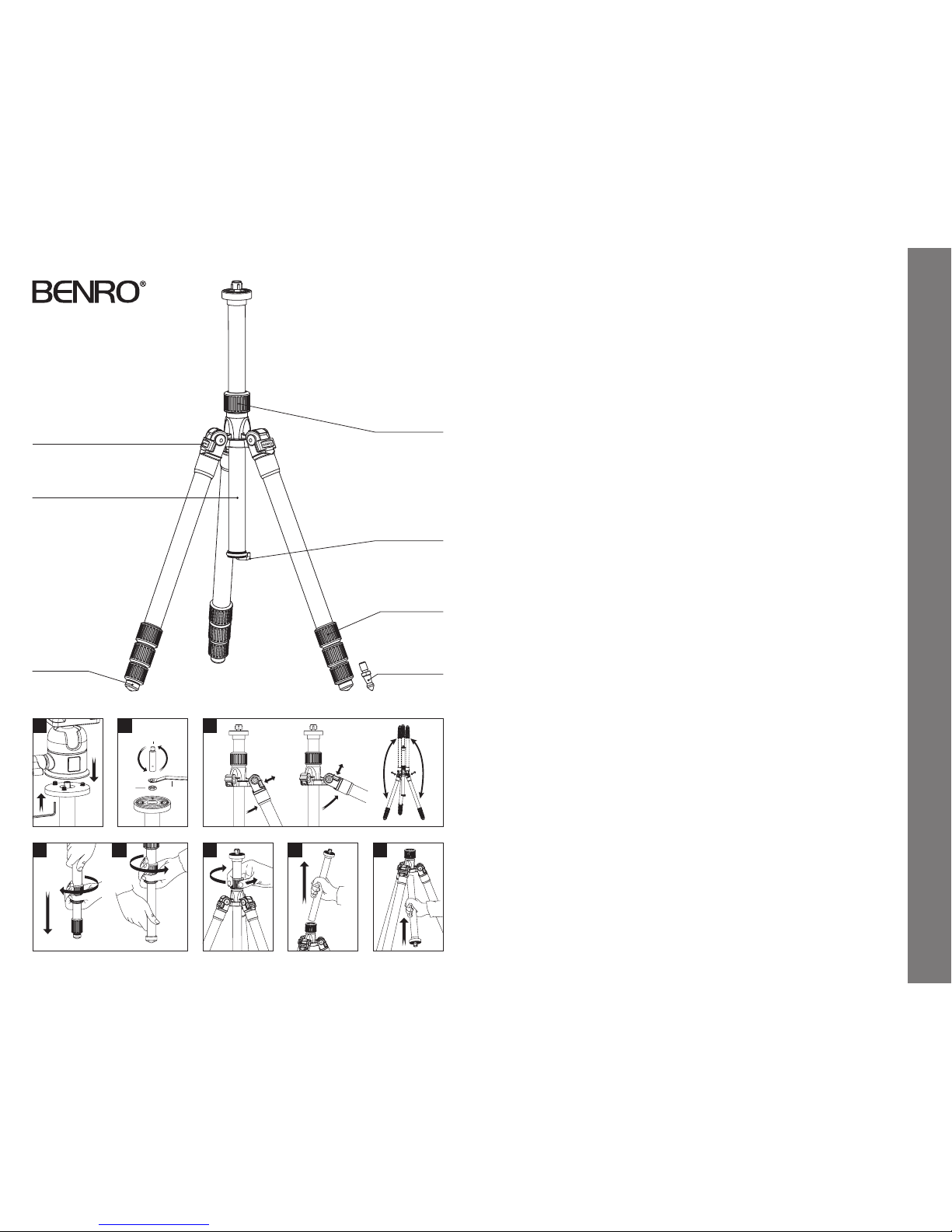
SETUP
Head Mount ing FIGURES 1 & 2
If your Tripod did not come wit h a Head,
select one o f the fine Benro Ballheads or
Panheads that match your siz e Tripod an d
install by screwing t he Head clockwise
onto the 3/8" Mounting Thre ad of the Top
Plate. Once it is hand tight, s ecure by fully
tightening the Head Lo cking Screw(s) (on
select models) from below.
Most Heads have a 3/8" base m ount so
your Benro Tripod is shippe d with the
3/8 Mounting Thread ex posed, but if the
Head you choose us es a 1/4–20 you can
attach it by simpl y reversing the Mounting
Screw. To do this turn the Locking Nut
counter-clock wise (using the supplied
Wrench) until it becomes lo ose, and
unscrew the Mounting S crew until it can
be completely rem oved. Reverse the Screw,
so that the threads are in p osition and
screw it back into place, s ecure with the
Locking Nut using the Wrench.
NOTE: Allow enough o f the screw threads
to be available for ma ximum security
when the Tripod Head is mou nted onto
the Tripod. It’s recomme nded that at least
5 to 6 threads be expo sed before locking
the Mounting Screw in p lace.
OPERATION
Before using your Tripod, a djust each Leg
Section to the d esired height and Leg
Angle Setting.
Make sure that the Tripod is fir mly resting
on a level surface a nd mount your camera
securely on the Tripod H ead. Always
engage any safet y locks on the Tripod Head
to prevent any accidental dismounting.
FOR BEST RESULTS: Do not raise th e Tripod
higher than necess ary and extend the
largest diameter L eg Sections first. On ly
extend the Center Co lumn if required to
reach maximum hei ght or to fine-tune the
vertical position.
FOR EXTR A STABILIT Y: Care fully hang
your camera bag o r other weight on the
Retractab le Spring-Loaded Weight Hoo k at
the bottom of the Ce nter Column.
NOTE: Never carr y your Trip od with camera
gear attached.
Leg Angle Adju stment
FIGURE 3
To accommodate uneven terrain, awk ward
shooting situations or for low angle shooting,
your Benro Tripod include s a 2-p osition Leg
Angle Adjustment Sli ding Lock. Each Leg can
be adjusted by pulli ng the Leg Angle Lock
out and selec ting one of the two positions.
Please make sure that the Le g Angle Lock is
securely pushe d back into the lock position
after you have sele cted the desired Leg Angle.
After use, the Leg A ngle Adjustment Sliding
Lock releases the Travel Angel ’s uniqu e
Tripod Legs so they can be f olded up 180°
making it ex tremely compact for easy
carrying and packing.
Leg Section Adjustment
FIGURES 4 & 5
Each Leg sec tion can be adjusted to the
desired length by tu rning the leg lock grip
1/2 turn (180°) clockwise until the Leg is f ree
to slide in or out. Once th e desired length is
achieved, turn the Le g Lock Grip counterclockwise unt il the Leg Section is securely
locked. Repeat t his step for each Leg and
each Section u ntil the Tripo d is set to the
desired height.
NOTE: To prevent any accidental damag e
to your gear, always remove any mounted
equipment (camera , etc.) from the Tripod
before adjusting the Leg Sections .
Raising an d Lowering the Center Colu mn
FIGURE 6
To raise or lower the Center Column, tur n
the Center Column Locki ng Knob clockwise
and set the Column to the d esired position.
While holding the Co lumn in position, turn
the Center Column Locki ng Knob counterclockwise to s ecure the Column in place.
Don’t over-tighten the Center Co lumn Lock,
as this could damage the th reads.
NOTE: Take special care when ra ising or
lowering the Center Colum n, if a camera or
equipment is mounte d on the Trip od. Never
loosen the Center Colu mn Locking Knob
without holding the Center Column. Failure
to follow these instr uctions could result in
damaged equipment.
Reversible Ce nter Column
FIGURES 7 & 8
Your Tripod has the ability to revers e the
Center Column for close -up photography,
copy work and for dif ficult to reach objects.
To reverse the Center Column, unscrew th e
Retractab le Weight Hook located on the
bottom of the Cente r Colu mn. Loosen the
Center Column Lockin g Knob and pull
the Center Column out. Ins ert the Center
Column through the bo ttom with the
Mounting Plate upside -down and retighten
the Center Column Locki ng Knob securely.
The Center Column has an anti -twist groove
(on select mod els), be sure to li ne-up the
groove with the key befo re inserting the
Column back into the Main C asting.
NOTE: Do not revers e the Center Column
when a camera or e quipment is mounted.
Center Column
Locking Knob
Retractable
Weight H ook
Leg Lock Grip
Leg Angle Adjustme nt Lock
Rubber Foot
Interchangeable
Spiked Fo ot
(on select models)
Reversible Center Column
3
Unlock Lock
4 5
Locking
Nut
1/4-20 + 3/8
Mounting Screw
Wrench
21
6 7 8
Operating Instructions
(continued on back page)
 Loading...