

75 Virginia Road
North Whit e Plains, NY 10603
T 914.347.3300
F 914.347.3309
info@BenroUSA.com
BenroUSA.com
HD Series 3-Way Panhead
Operating Instructions
Thank you for making Benro your choice for professional photographic
equipment. Your Benro gear is manufactured to provide years of
dependable service. In order to obtain optimum satisfaction and
performance, we suggest that you carefully read these instructions.
Specificati ons and design are subjec t
to change without notice.
1 2
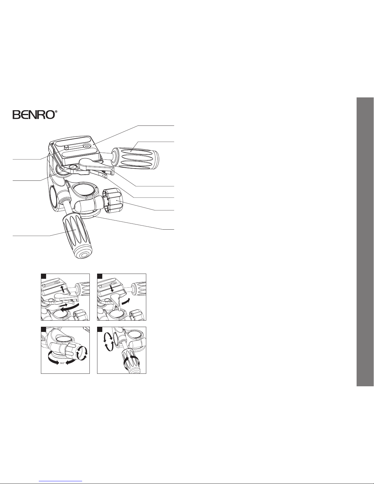
Quick Release Plate
Horizontal Tilt Lock
Plate Locking Lever
Pan Lock
Base
Mounting Screw
Front/Rear Tilt Lo ck
Security Locking Lever
Bubble Level
SETUP
Head Mounting
Install by screwin g the head clockwise onto
the 3/8" Mounting Threa d of the Top Plate of
the Tripod or Monopo d. Once it is hand tight,
secure by fully tighte ning the Head Locking
Screw(s) (on select models) from below.
OPERATION
Three-way p ositioning of camera and
lens movement is direc tly controllable
on the HD Series 3- Way Panheads. Two
comfortable Handles provide both
movement and lock ing of front to rear
Tilt, and side to sid e Tilt. Plus, a separate
Locking Knob p ermits the entire Head
assembly to move fre ely within a 360°
rotational adjustment.
Quick Release Plate
The HD Series 3- Way Panheads incor porate
a Quick Release Plate s ystem. It offers a
quick method of mo unting or releasing a
Camera or Equipme nt from the Head. It’s
important th at the correct Quick Release
Plate be used along w ith the proper
mounting screw (1/4–20 is included as the
standard size but s pare 1/4–20 and 3/8
plates are available as acce ssories). Extra
Plates are recommende d as you can screw
one to each Camera or L ens for even greater
convenience when rapidly mounting and
dismounting gear.
Quick Release Locking Lever
(FIGURES 1 & 2)
When used prop erly, the patented Dual
Lock Quick Releas e system offers two levels
of security f or your gear. To remove the
Quick Release Plate, s queeze both the Plate
Locking Lever and th e Security Locking
Lever and pull the large r Locking Lever
out. The Quick Re lease Plate will disengage
allowing it to be remove d.
To reconnect the Quick Re lease Plate, insert
the angled par t of the Plate into the groove
on the opposite side o f the Locking Levers
and press down fl at. The Locking Levers will
automatically eng age the locking system and
will return to the saf ety lock position. Press
the Plate Locking Lever in f irmly to secure.
Pan Control
(FIGURE 3)
Horizontal rot ation or Panning can be easily
accomplished by f irst loosening the Pan Lock
and then rotating He ad on Platform. Once
in position tighten th e Pan Lock securely.
NOTE: Do not over tighten t he Pan Lock as
this could damage the lo cking mechanism.
Tilt Contro l
(FIGURE 4)
Front to Rear Angle or Tilt a djustments can
be easily accomplishe d by first loosening
the Tilt Lock (be sur e to hold on firmly to
balance weight of the ca mera). Position as
required and then t ighten Handle securely.
You have the same Control and Lock
available on the othe r axis for Horizontal
Angle or Tilt adjus tments.
NOTE: Do not over tighten t he Tilt Locks as
this could damage the lo cking mechanism.
FOR ADDITIONAL CONTROL: Depending
on your requiremen ts you may find it
convenient to reorient th e camera or lens
90° on the Quick R elease Plate and remount
so that the Tilt Control s give you different
positioning support.
USER NOTICE
• Do not exceed the ma ximum specified
load capacit y (see specifications at
www.BenroUSA.com).
• Always ensure that all Panhea d locks are
tightly engaged b efore mounting any gear.
• Always clean and dr y any Panhead after
it has been exp osed to wet, dusty, sandy
or salty condi tions. Your Panhead is n ot
recommended fo r use in salt water. If
required, clean Pan head using a mild
soap solution ap plied with a soft cloth,
rinse with fresh wate r and dry with soft
towel. Remove any dust, dir t or sand from
all locks and all m oving parts.
• Do not leave any Panhead in the su n
for prolonge d periods and avoid high
temperature exposure.
• Avoid leaving any Tripod or Monop od
unattended in a reas where people could
trip over the gear and ge t hurt.
• Remove camer a, lens, and all gear from any
Tripod or Monopod when transporting.
• For your safety, don’t l et your Benro
gear come in contac t with any electrical
power source.
3 4
Operating Instructions & User Notice
 Loading...