

DJ Series Tilthead
75 Virginia Road
North Whit e Plains, NY 10603
T 914.347.3300
F 914.347.3309
info@BenroUSA.com
BenroUSA.com
Operating Instructions
Thank you for making Benro your choice for professional photographic
equipment. Your Benro gear is manufactured to provide years of
dependable service. In order to obtain optimum satisfaction and
performance, we suggest that you carefully read these instructions.
Specificati ons and design are subjec t
to change without notice.
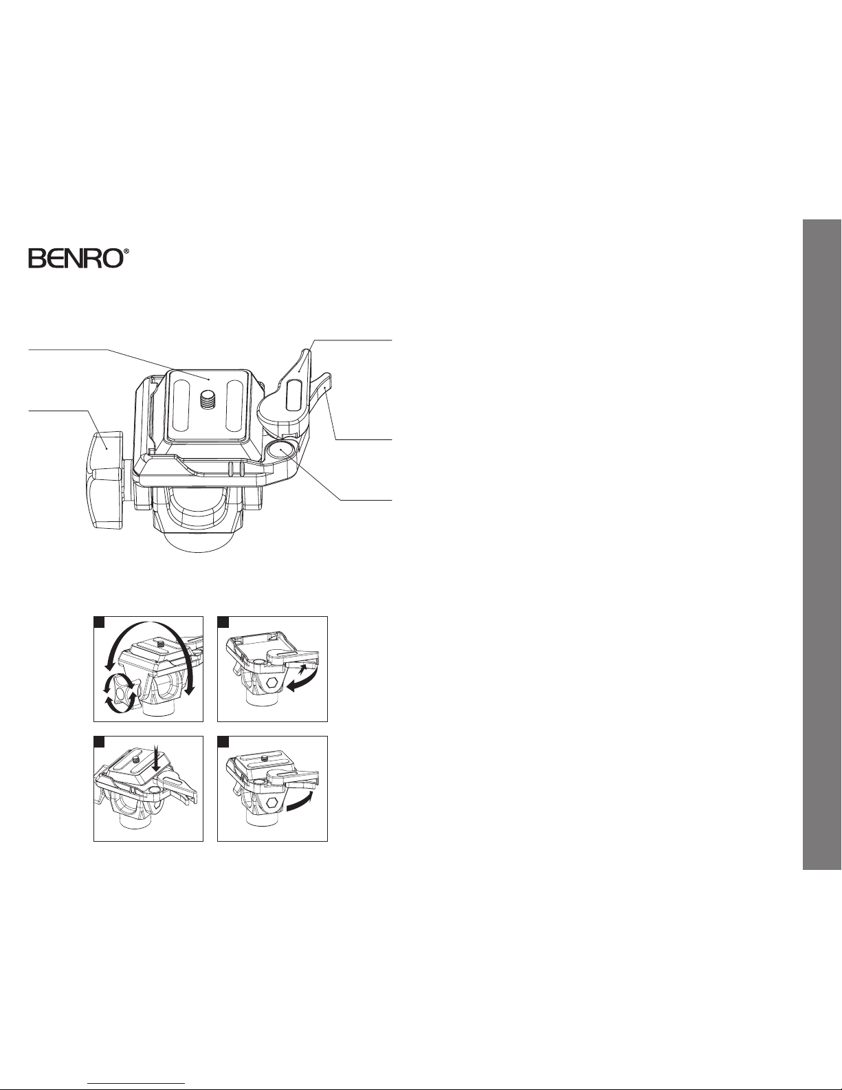
Bubble Level
Quick Release Plate
Tilt Lock Knob
Securi ty
Locking Lever
Plate Locking Lever
SETUP
Head Mounting
Install by screwin g the head clockwise onto
the 3/8" mounting thread of t he top plate
of the Monopod . Once it is hand tight, if
available, secure by f ully tightening the
Head Locking Sc rew(s) (on select m odels)
from below.
OPERATION
Positioning Adjustments (FIGURE 1)
Horizontal rotation or panning can be
easily accomplished by s wiveling the
entire Monopod.
Front to rear angle or tilt adjus tments can
be easily accomplishe d by first loosening
the Tilt Lock Kno b (be sure to hold firmly to
balance weight of the ca mera). Position as
desired and tighten th e Knob securely.
Depending on your requirements, you may
find it convenient to re orient the camera or
lens 90° on the Qu ick Release Plate and then
remount. This allo ws the Tilt Control Knob
to give you differe nt positioning support.
NOTE: Do not over tighten t he Locking
Knob as this could dama ge the Tilthead
locking mechanism.
Quick Release Plate
The DJ Series Tilthe ad incorporates a Quick
Release Plate syste m. It offers a quick
method of mountin g or releasing a Camera
or Equipment from th e Head. It’s important
that the correct Q uick Release Plate be used
along with the prop er mounting screw
(1/4–20 is included as t he standard size but
spare 1/4–20 and 3/8 plates are available as
accessories). Extr a Plates are recommended
as you can screw one to each C amera or
Lens for even greater convenience when
rapidly mounting and dismounting gear.
Quick Release Locking Lever
(FIGU RES 2, 3 & 4)
When used prop erly, the patented Dual
Lock Quick Releas e system offers two levels
of security f or your gear. To remove the
Quick Release Plate, s queeze both the Plate
Locking Lever and th e Security Locking
Lever and pull the large r Locking Lever
out. The Quick Re lease Plate will disengage
allowing it to be remove d.
To reconnect the Quick Re lease Plate, insert
the angled par t of the Plate into the groove
on the opposite side o f the Locking Levers
and press down fl at. The Locking Levers will
automatically eng age the locking system and
will return to the saf ety lock position. Press
the Plate Locking Lever in f irmly to secure.
USER NOTICE
• Do not exceed the ma ximum specified
load capacit y (see specifications at
www.BenroUSA.com).
• Always ensure that all Til thead locks
are tightly engage d before mounting
any gear.
• Always clean and dr y any Tilthead after
it has been exp osed to wet, dusty, sandy
or salty condi tions. Your Tilthe ad is not
recommended fo r use in salt water. If
required, clean b allhead using a mild
soap solution ap plied with a soft cloth,
rinse with fresh wate r and dry with soft
towel. Remove any dust, dir t or sand from
all locks and all m oving parts.
• Do not leave any Tilthea d in the sun
for prolonge d periods and avoid high
temperature exposure.
• Avoid leaving any Tripod or Monop od
unattended in a reas where people could
trip over the gear and ge t hurt.
• Remove camer a, lens, and all gear from any
Tripod or Monopod when transporting.
• For your safety, don’t l et your Benro
gear come in contac t with any electrical
power source.
1
3
2
4
Operating Instructions & User Notice
 Loading...