

Reversible Ce nter Column (FIGURES 7 & 8)
Your Tripod has the ability to revers e the
Center Column for close -up photography,
copy work and for dif ficult to reach objects.
To reverse the Center Column, unscrew
the Retract able Weight Hook located
on the bottom of th e Center Column.
Loosen the Center Colum n Locking Knob
and pull the Center Column o ut. Insert
the Center Column through t he bottom
with the Mounting Plate upside -down and
retighten the Center Colum n Locking Knob
securely. The Center Colum n has an antitwist groove, be s ure to line-up the groove
with the key before ins erting the Column
back into the Main Cast ing.
NOTE: Do not revers e the Center Column
when a camera or e quipment is mounted.
User Adjustments
(FIGURES 9 & 10)
Leg Angle Hinge Pivot te nsion can be
adjusted using the 4m m Allen Key. Flip Lock
Lever tension is adjuste d using the 3mm
Allen Key plus the spe cial Six-sided Socket
Wrench built into the plas tic clip which
comes attache d to one of the tripod legs.
USER NOTICE
• Do not exceed the ma ximum specified
load capacit y (see specifications at
www.BenroUSA.com).
• Always ensure that Leg and H ead Locks
are tightly engage d before mounting any
gear on your Tripod.
• Always clean and dr y any Tripod afte r it
has been expo sed to wet, dusty, sandy
or salty condi tions. Your Tripod is not
recommended fo r use in salt water. If
required, clean tripod using a mild soap
solution applie d with a soft cloth, rinse
with fresh water and dr y with soft towel.
Remove any dust, dir t or sand from all Leg
Locks, Leg Se ctions and all moving part s.
• Do not leave any Tripod in the sun for
prolonged p eriods and avoid high
temperature exposure.
• Avoid leaving any Tripod or Monop od
unattended in a reas where people could
trip over the gear and ge t hurt.
• Remove camera, l ens, and all gear from
any tripod when transporting.
• For your safety, don’t l et your Benro
gear come in contac t with any electrical
power source.
Classic Series Tripods
75 Virginia Road
North Whit e Plains, NY 10603
T 914.347.3300
F 914.347.3309
info@BenroUSA.com
BenroUSA.com
Operating Instructions
Thank you for making Benro your choice for professional photographic
equipment. Your Benro gear is manufactured to provide years of
dependable service. In order to obtain optimum satisfaction and
performance, we suggest that you carefully read these instructions.
Specificati ons and design are subjec t
to change without notice.
Operating Instructions & User Notice
SETUP
Head Mount ing (FIGURES 1 & 2)
If your Tripod did not come wit h a Head,
select one o f the fine Benro Ballheads or
Panheads that match your siz e Tripod and
install by screwing t he Head clockwise
onto the 3/8" Mounting Thre ad of the Top
Plate. Once it is hand tight, s ecure by fully
tightening the Head Lo cking Screw(s) (on
select models) from below.
Most Heads have a 3/8" base m ount so
your Benro Tripod is shippe d with the 3/8
Mounting Thread e xposed, but if the Head
you choose uses a 1/4–20 you can attach it
by simply reversing th e Mounting Screw.
To do this turn the Locking Nut counte rclockwise (using th e supplied Wrench)
until it becomes lo ose, and unscrew the
Mounting Screw until it c an be completely
removed. Reverse t he Screw, so that the
threads are in positio n and screw it back
into place, secure with t he Locking Nut
using the Wrench.
NOTE: Allow enough o f the screw threads
to be available for ma ximum security
when the Tripod Head is mou nted onto the
Tripod. It’s recommen ded that at least 5 to
6 threads be expo sed before locking the
Mounting Screw in place.
OPERATION
Before use, adjus t each Leg Section to the
desired height and L eg Angle Setting.
Make sure that the Tripod is fir mly resting
on a level surface a nd mount your camera
securely on the Tripod H ead. Always
engage any safet y locks on the Tripod Head
to prevent any accidental dismounting.
FOR BEST RESULTS: Do not raise th e Tripod
higher than necess ary and extend the
largest diameter L eg Sections first. On ly
extend the Center Co lumn if required to
reach maximum hei ght or to fine-tune the
vertical position.
FOR EXTR A STABILITY: Carefu lly hang
your camera bag o r other weight on the
Retractab le Spring-Loaded Weight Hoo k at
the bottom of the Ce nter Column.
NOTE: Never carr y your Tripod wit h camera
gear attached.
Leg Angle Adju stment
(FIGURE 3)
To accommodate uneven terrain, awk ward
shooting situatio ns or for low angle
shooting, your Be nro Tripod include s a
3-position Leg Angle Adjustment Sliding
Lock. Each Leg can be adjus ted by pulling
the Leg Angle Lock ou t and selecting one
of the three positio ns. Please make sure
that the Leg Angle Loc k is securely pushed
back into the lock posi tion after you have
selected th e desired Leg Angle.
Leg Section Adjustment
(FIGURES 4 & 5)
Each Leg sec tion can be adjusted to the
desired length by o pening the Flip Lock
Lever so the Leg is free to s lide in or out.
Once the desired le ngth is achieved, snap
the Flip Lock Lever close d so that the Leg
Section is se curely locked. Repeat this step
for each Leg and each S ection until the
Tripod is set to the desired he ight.
NOTE: To prevent any accidental damag e
to your gear, always remove any mounted
equipment (camera , etc.) from the Tripod
before adjusting the Leg Sections .
Raising an d Lowering the Center Colu mn
(FIGURE 6)
To raise or lower the Center Column, tur n
the Center Column Locki ng Knob clockwise
and set the Column to the d esired position.
While holding the Co lumn in position, turn
the Center Column Locki ng Knob counterclockwise to s ecure the Column in place.
Don’t over-tighten the Center Co lumn Lock,
as this could damage the th reads.
NOTE: Take special care when ra ising or
lowering the Center Colum n, if a camera or
equipment is mounte d on the Tripod. N ever
loosen the Center Colu mn Locking Knob
without holding the Center Column. Failure
to follow these instr uctions could result in
damaged equipment.
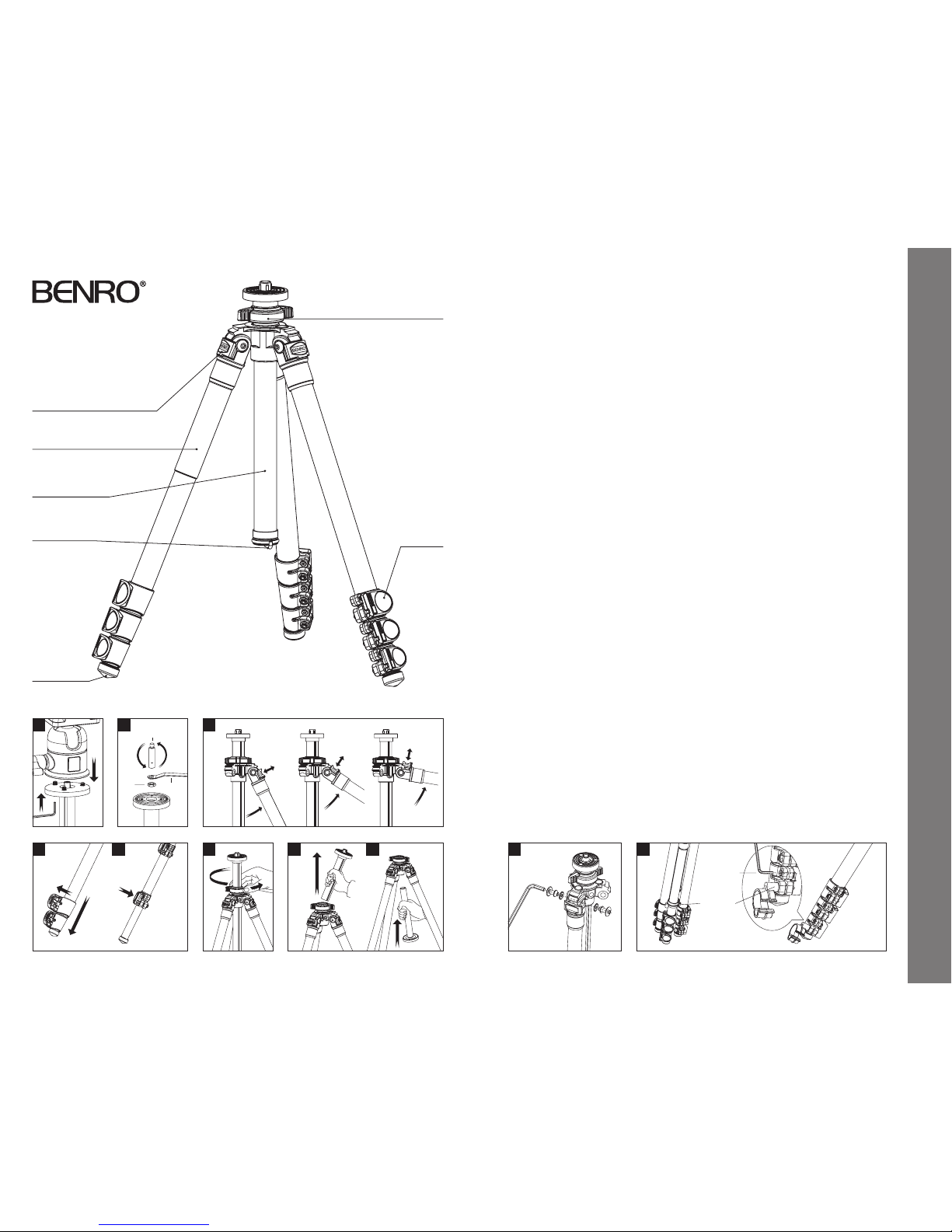
Center Column
Locking Knob
Retractable
Weight H ook
Flip Lock Lever
Closed Cell Foam Grip
Leg Angle Adjustme nt Lock
Rubber Foot
Reversible Grooved
Center Column
3
Unlock Lock
4 5
1
6
Locking
Nut
1/4-20 + 3/8
Mounting Screw
Wrench
2
7 8 9
3mm Allen Key
6-sided Socket
Wrench Clip
10
(continued on back page)
Operating Instructions
 Loading...