

BH Series Single-Action Ballheads
75 Virginia Road
North Whit e Plains, NY 10603
T 914.347.3300
F 914.347.3309
info@BenroUSA.com
BenroUSA.com
Operating Instructions
Thank you for making Benro your choice for professional photographic
equipment. Your Benro gear is manufactured to provide years of
dependable service. In order to obtain optimum satisfaction and
performance, we suggest that you carefully read these instructions.
Specificati ons and design are subjec t
to change without notice.
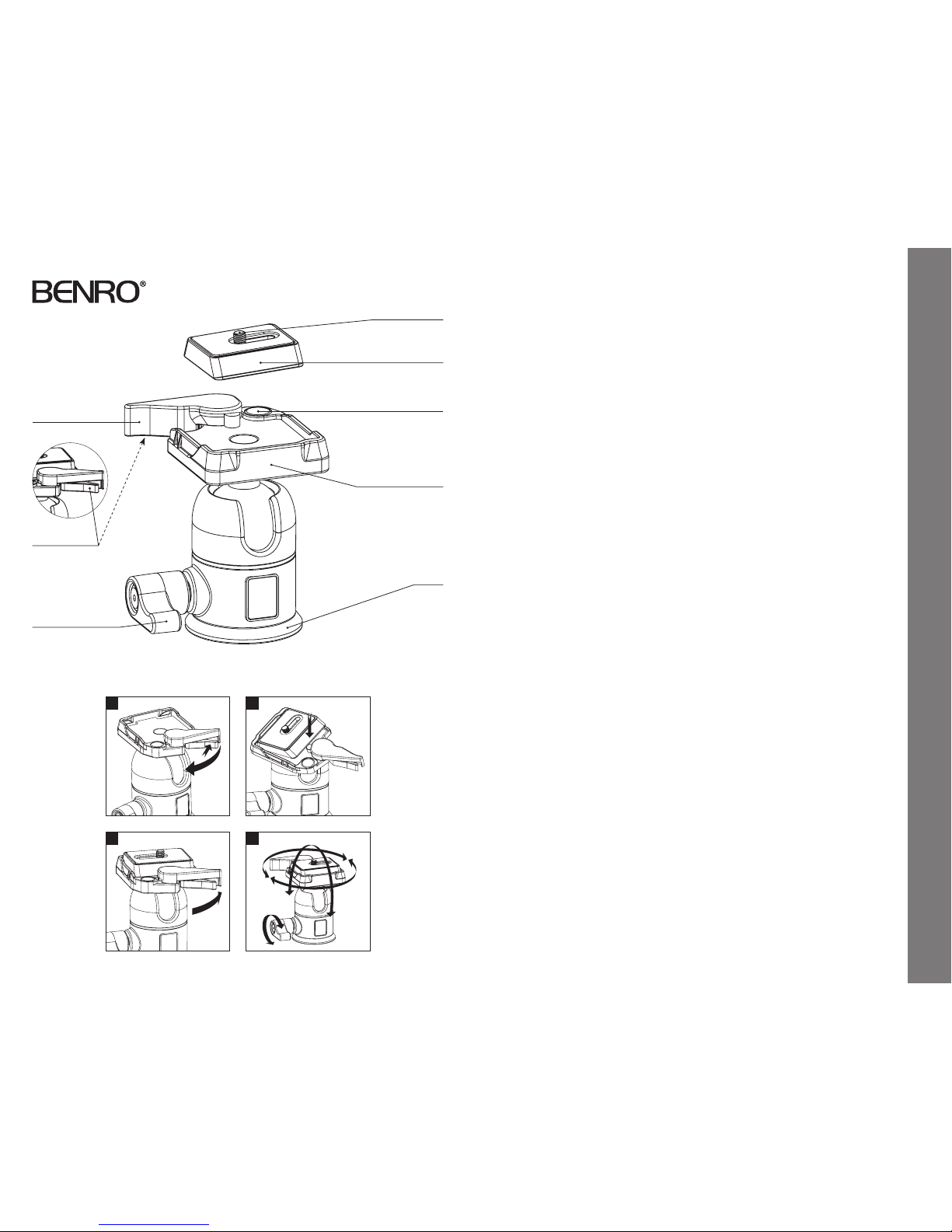
Camera Screw
Quick Release Plate
Bubble Level
Base
Plate Locking Lever
Ball Locking Lever
Securi ty
Locking Lever
Mounting Platform
Head Mounting
Install by screwin g the head clockwise onto
the 3/8" Mounting Threa d of the Top Plate of
the Tripod or Monopo d. Once it is hand tight,
secure by fully tighte ning the Head Locking
Screw(s) (on select models) from below.
OPERATION
The single-a ction Ball Locking Lever
controls all movements o f the BH Series
Ballh eads. Whe n released, the Ballhead and
the Mounting Platform can move fre ely
within a 360° rotat ional adjustment. And
two U-shap ed openings on opposite sides
provide 90° ang ular movement of the
Mounting Platfo rm.
Quick Release Plate
The BH Series Sing le-Action Ballheads
incorporate a Quic k Release Plate system.
It offers a qui ck method of mounting or
releasing a Camer a or Equipment from the
Head. It’s impo rtant that the correct Quick
Release Plate be use d along with the proper
mounting screw (1/4–20 is included as the
standard size but s pare 1/4–20 and 3/8
plates are available as acce ssories). Extra
Plates are recommende d as you can screw
one to each Camera or L ens for even greater
convenience when rapidly mounting and
dismounting gear.
Quick Release Locking Lever
(FIGU RES 1, 2 & 3)
When used prop erly, the patented Dual
Lock Quick Releas e system offers two levels
of security f or your gear. To remove the
Quick Release Plate, s queeze both the Plate
Locking Lever and th e Security Locking
Lever and pull the large r Locking Lever
out. The Quick Re lease Plate will disengage
allowing it to be remove d.
To reconnect the Quick Re lease Plate, insert
the angled par t of the Plate into the groove
on the opposite side o f the Locking Levers
and press down fl at. The Locking Levers will
automatically eng age the locking system and
will return to the saf ety lock position. Press
the Plate Locking Lever in f irmly to secure.
Ball Lock ing Lever
(FIGURE 4)
The single-a ction Ball Locking Lever is
spring-loaded and can be repositioned when
it is in the lock positi on to accommodate
any desired Lever position. To reposition,
gently pull on the Lever to d isengage, and
then allow the spring to p ull the lever back
to reengage.
NOTE: Do not over tighten t he Locking
Lever as this could damage th e Ballhead
locking mechanism.
1 2
3
360°
180°
4
• Do not exceed the ma ximum specified
load capacit y (see specifications at
www.BenroUSA.com).
• Always ensure that all Ballh ead locks are
tightly engaged b efore mounting any gear.
• Always clean and dr y any ballhead after
it has been exp osed to wet, dusty, sandy
or salty condi tions. Your Ballhea d is not
recommended fo r use in salt water. If
required, clean B allhead using a mild
soap solution ap plied with a soft cloth,
rinse with fresh wate r and dry with soft
towel. Remove any dust, dir t or sand from
all locks and all m oving parts.
• Do not leave any Ballhead in t he sun
for prolonge d periods and avoid high
temperature exposure.
• Avoid leaving any Tripod or Monop od
unattended in a reas where people could
trip over the gear and ge t hurt.
• Remove camer a, lens, and all gear from any
Tripod or Monopod when transporting.
• For your safety, don’t l et your Benro
gear come in contac t with any electrical
power source.
USER NOTICESETUP
Operating Instructions & User Notice
 Loading...