

B Series Double-Action Ballheads
75 Virginia Road
North Whit e Plains, NY 10603
T 914.347.3300
F 914.347.3309
info@BenroUSA.com
BenroUSA.com
Operating Instructions
Thank you for making Benro your choice for professional photographic
equipment. Your Benro gear is manufactured to provide years
of dependable service. In order to obtain optimum satisfaction and
performance, we suggest that you carefully read these instructions.
Specificati ons and design are subjec t
to change without notice.
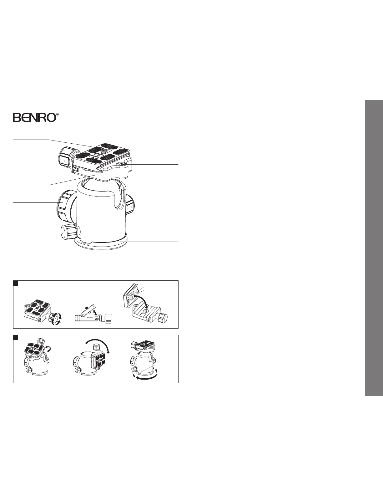
Mounting Screw
Stop Screws (2)
Head Locking K nob
Mounting Screw
Mounting Platform
Bubble Level
SETUP
Head Mounting
Install by screwin g the head clockwise onto
the 3/8" Mounting Threa d of the Top Plate of
the Tripod or Monopo d. Once it is hand tight,
secure by fully tighte ning the Head Locking
Screw(s) (on select models) from below.
OPERATION
The B Series Dou ble-Action Ballheads are
professional black anodized machined
aluminum and feature three operating
Knobs. Drag con trol is manually adjusted
and locked, along with independent
Panning. Plus a Univers al Quick Release
Clamp with secondar y Safety Lock System
is incorporated.
Universal Quick Release Plate System
The B Series Dou ble-Action Ballheads
feature a Universal Q uick Release Plate
system. It of fers a quick method of
mounting or releasi ng a Camera or
Equipment from the H ead. It’s important
that the correct Q uick Release Plate be used
along with the prop er mounting screw
(1/4–20 is included as t he standard size
but spare 1/4–20 and 3/8 plates of various
lengths are availabl e as accessories). Extra
Plates are recommende d as you can screw
one to each Camera or L ens for even greater
convenience when rapidly mounting
and dismounting gear. And b ecause of
compatibility w ith the Universal system,
most plates and spe cial brackets from other
manufacture rs can be used as well.
Quick Rel ease Lock
(FIGURE 1)
When used prop erly, the Quick Release
Lock offer s two levels of security for your
gear. To remove the Quick Release Plate,
turn the Quick Rele ase Locking Knob
counter-clock wise. A partial opening of
the clamping mecha nism allows the Quick
Release Plate to slide on t he Mounting
Platform for proper balance and positioning.
Two Stop Screws (removable) on the bottom
of the Quick Releas e Plate provide this first
level of securit y. An additiona l counterclockwise tu rn of the Quick Release Locking
Knob opens the cl amp fully so that the
Quick Release Plate c an be tilted out to
be removed. Rever se the process and
tighten the Quick Rel ease Locking Knob
to secure the Quick Re lease Plate.
Ballhead Controls
(FIGUR E 2)
A large Head Lock ing Knob locks the
Ballhead in place. Once the Knob is
turned counter-clo ckwise and loosened,
the Ballhead can move f reely allowing
the Mounting Platf orm to be positioned
anywhere withi n a 0–90° vertical
orientation. This movement is expanded by
the use of the Pan Locki ng Knob
which adds a 360° Pann ing range. The Pan
control is fully independent and positioning
can be adjusted eas ily and accurately by
using the Graduate d Panning Scale and
Pointer on the Base of the B allhead.
When the Head Lock ing Knob is released,
it is possible to move the B allhead with
some resistance o r Drag. To achieve the
proper degre e of Drag, mount the intended
camera or equip ment onto the Ballhead.
While holding the camera/lens loosen the
Head Locking K nob until it is released.
Turn the Drag Control Knob cl ockwise to
increase Drag, and cou nter-clockwise to
decrease it.
FOR OPTIMUM RESULTS: Adjust the D rag
under the weight cap acity, temperature
and conditions under which the Ballhead
will be used.
NOTE: Do not over tighten a ny Locking
Knobs as this could dam age the Ballhead
locking mechanism.
USER NOTICE
• Do not exceed the ma ximum specified
load capacit y (see specifications at
www.BenroUSA.com).
• Always ensure that all Ballh ead locks are
tightly engaged b efore mounting any gear.
• Always clean and dr y any Ballhead after
it has been exp osed to wet, dusty, sandy
or salty condi tions. Your Ballhea d is not
recommended fo r use in salt water. If
required, clean B allhead using a mild
soap solution ap plied with a soft cloth,
rinse with fresh wate r and dry with soft
towel. Remove any dust, dir t or sand from
all locks and all m oving parts.
• Do not leave any Ballhead in t he sun
for prolonge d periods and avoid high
temperature exposure.
• Avoid leaving any Tripod or Monop od
unattended in a reas where people could
trip over the gear and ge t hurt.
• Remove camer a, lens, and all gear from any
Tripod or Monopod when transporting.
• For your safety, don’t l et your Benro
gear come in contac t with any electrical
power source.
Drag Control Knob
Base
Pan Locking Knob
Quick Release
Locking Knob
1
2
Panning
Scale Pointer
360°
Operating Instructions & User Notice
 Loading...