

Page 1
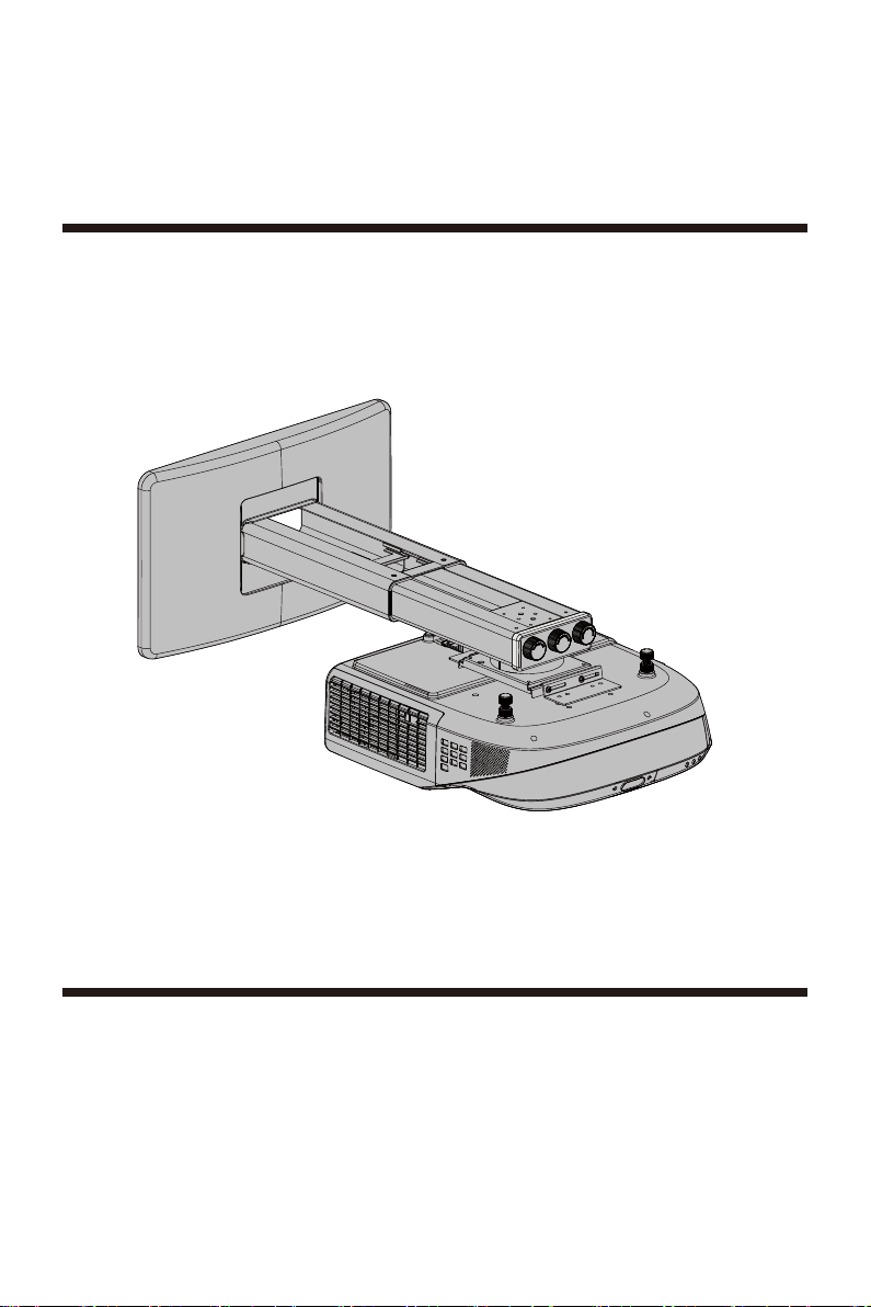
Installation Manual
Model: WM03G5
●
Be sure to read t his man ual tho roughly and to do th e insta llation work saf ely.Keep
this m anual a vaila ble for future ref erenc e.
●
Suffic ient ex pertise is requi red for i nstalling this p rojec tor wal l mount.
●
Do not u se the pr oject or wall mount for pu rpose s other than for whi ch it is de signed.
Page 2
Important Safety
E N G L I S H
Be sure t o re ad th is m anual t ho rou gh ly to do th e in sta ll ation w or k.
Only qu al ified s er vice pe rs onnel ( tw o or more ) sh oul d ca rr y out i ns talla ti on or dis mo untin g of t he proj ec tor
2
from th e pr oject or w all mou nt .
Use wit h pr oduct s he avi er t ha n the m ax imum we ig hts(W eight C ap aci ty: <15kg ) in dic at ed may
resul t in i nstab il ity c au sing po ss ible in ju ry.
For saf et y reaso ns , check t he s tre ng th of the w al l befor e in stall at ion. If t he w all is no t st rong
3
enoug h, r einfo rc e it suff icien tl y bef or e in sta ll ation .
Do not ma ke a ltera ti ons to th e pr oject or w all m ou nt.
4
Do not in st all the p ro jecto r wa ll moun t on a w all s ub ject to v ib ratio n or i mpact .
5
To avoid fi re , do not in st all the p ro jecto r wi th th e pr oject or w all mou nt i n a humid o r ex cessi ve ly dust y pl ace.
Use the s up plied a cc essor ie s only. Us e of acce ss ories o th er th an t hose su pp lied ma y re sult in d am age to
7
the pro je ctor wa ll m ount.
When di sm ounti ng t he proj ec tor fro m th e pro je ctor wa ll m ount, b e su re to unp lu g the AC pow er c ord and
8
other c on necti ng c ables b ef oreha nd .
Do not hi t or h ang any h ea vy obje ct s on the pr oj ector w al l mou nt . If the pr oj ector w al l mount i s da maged ,
9
stop us e an d conta ct a q ualif ie d servi ce p erson i mm edi at el y.
Pleas e in stall t hi s appar at us only o n th e horiz on tal s ur face in st ead of th e sl antin g on e.
* Manuf ac turer i s no t lia bl e for any d am ages or i nj ury cau se d by mish an dli ng o r impro pe r insta ll ati on .
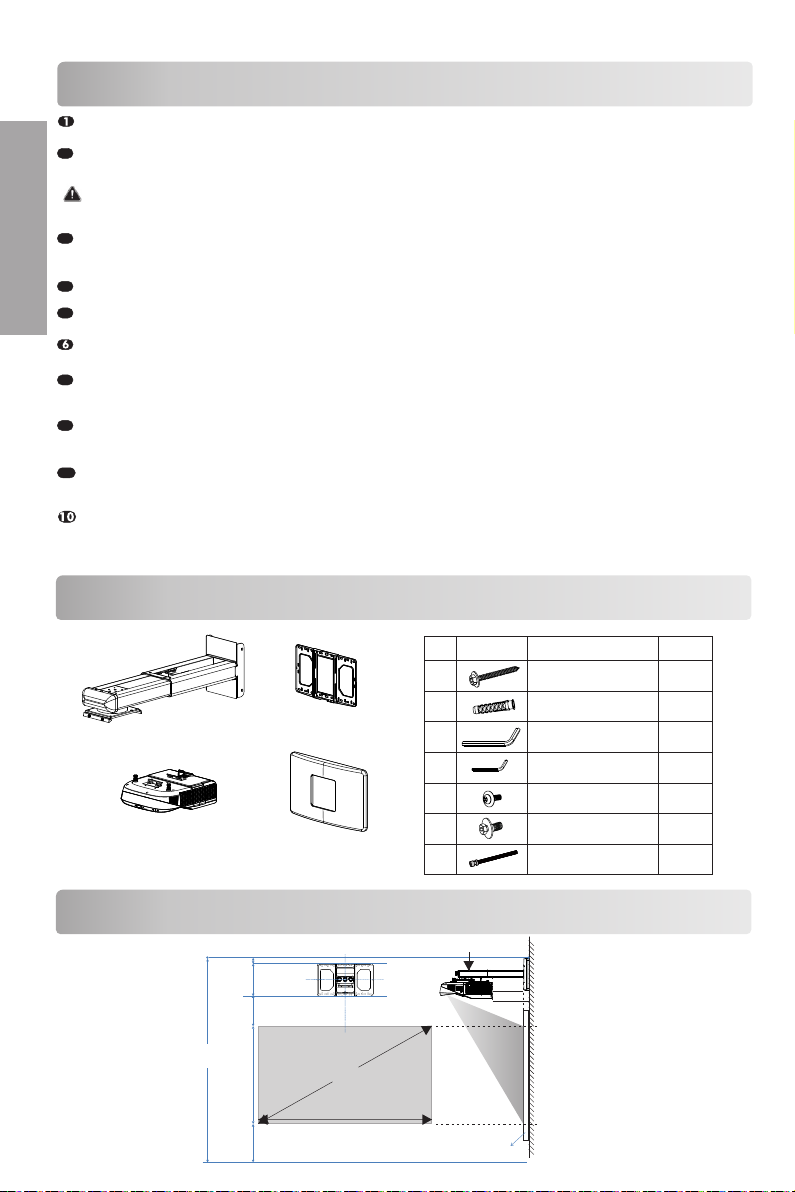
Checking The Supplied Accessories
Setting pla te ( 1)
Projector ( with the proj ec to r
mounting pl at e) (1)
Wal l pl ate (1)
Wal l pl ate cover (1)
Checking The Installation Position
Center
Center
M
w
Scale value = D
30mm
Plate height 260mm
With cover 270mm
Ceiling height(H)
=30mm+ Plate height
+V+h+F
V
H
F
dia gramm atic
NO
pre senta tion
a
b
c
d
e
f
g
Thickness of the screen.
desig natio n
Scr ew(M 6X 55)
Φ10mm An ch or bo lt
L5Allen k ey
L3Allen k ey
Scr ew(M 4X 10)
Scr ew(M 6X 15)
Regulating lead screw
a
D
X
quant ity
5
5
1
1
4
4
1
Page 3
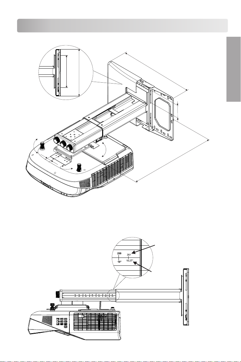
Checking The Installation Position
190mm
270mm
Set pla te
Wal l plate
450mm
Regul at ing ran ge
0~75m m
E N G L I S H
±5°
Regul a
0~30m m
t
in
g r
ange
±5°
±5°
315mm~535
m
m
● Accor di ng t o th e sc ale to determine th e sc re en s ize . Sc al e parameters are for
refere nc e on ly .
mm
inch
Page 4

To Set The Projector Wall Mount On The Wall
E N G L I S H
● Accor di ng t o th e sc ale to determine th e in st al la tion height of the wa ll p la te .
Scal e pa ra me te rs are for referenc e on ly .
* Please r ef er t he i nstallation chart in pr oj ec to r UM and QSG for proper insta ll at io n
evalua ti on .
87''
73''
78''
83''
88''
93''
100''
108''
90''
100''
105''
110''
120''
125''
130''
image
87''
90''
100''
105''
110''
73''
120''
125''
78''
130''
83''
88''
93''
100''
108''
Page 5

To Set The Projector Wall Mount On The Wall
● The brack et i s su itable fo r co nc re te wall mou nt in g or wooden stu d wa ll .
● Concret e wa ll m ounting thi ck ne ss must be a mi ni mu m 100mm. Ancho r bo lt a nd screw
(M6 × 55) are n ee de d to b e used for in st al lation.
● Dry-wal l mo un ti ng thickn es s mu st be a minim um 7 0m m. O nly screw (M 6 × 55 ) is needed
to be used fo r in st allatio n, a nd g yp sum board
thickne ss n ot g reater th an 3 /8 i nc h. If the wal l
is not stro ng e no ug h, reinfo rc e it s uff ic ie ntly
ø10 ~11mm
>55 mm
before in st al la tion.
● Please co nt ac t ma nufactu re r if y ou have
any quest io ns a bo ut mounti ng s ur face issu
Remov e the
decor ati ve c ove r
Loose t he sc re ws e
a
e.
Concr ete w al l mou nt ing
>55mm
ø3m m
Whe n insta llati on on the
woo d stud wa ll,th e stud
pos ition o f the mou nt wall
sur face sh all be de fined ,
c
the f ixed sc rew cen tral
poi nt shal l be alig ned wit h
the c entra l line of s tud.
Dry-wal l mo un ti ng
scr ew cent ral
poi nt
Use a nchor bol t
Not use anc ho r bo lt
E N G L I S H
b
a
c
screw (M6 × 5 5) a re n ee ded to be use d
for insta ll at ion in concre te w al l mountin g
d
g
c
a S cre w “ g” t o sett ing pla t e w ith L5 al le n ke y in ad van ce but .
do no t tig hte n it.
b L oos en th e s cre ws wi th L3 allen ke y, pull ou t the se tt in g .
pl at e and put th e p ow er ca bl e an d other c abl es th ro ug h
th e set tin g plat e.
screw (M6 × 5 5) a re n ee ded to be use d
for insta ll at ion in dry-wa ll m ou nting
To set the proj ec to r wa ll mount on t he w al l
Page 6

To Set The Projector Wall Mount On The Wall
● All ow to adj ust t he projector u pward/d ownward by
E N G L I S H
regu lating l ead sc rew.You can adj ust the projector
upwar d/ downwar d accordi ng to your need.
Adj ust t he up war d/
-do wnw ard s lide :75m m
No te : re gu lat ing lea d
sc rew m ust b e in the
slo t of w al l pla te.
● Move the ra is ed Wa ll p la te and adjust t he u pw ard/dow nw ar d slide.
Adj ust the u pward/d own wa rd
sli de:7 5m m
75mm
A
Wal l cov er
B
● Tight en th e screw “f” to wall pl ate but
do not ti ght en it . Fas ten it af ter locati ng
the re gul ating lead screw pos ition.
f
c
A
Adj ustme nt
dir ectio n
B
To Install The Projector On The Projector Wall Mount
Page 7

To Install The Projector On The Projector Wall Mount
● Move the mo ut in g plate and adj us t th e leftwar d/ ri ghtward s li de .
Adj ust the l eftwa rd/
rig htwar d slide :30mm
30m m
A
B
A
A
E N G L I S H
B
B
● Locking t he s cr ew e .
To Adjust The Vertical Tilt
A
B
Adj ustme nt butt ons
● Connect t he p ow er c able and ot he r ca bles to
the proje ct or.
Adjus tm ent dir ec tion
e
Con nect th e power c able
and o ther ca bles to t he proj ector.
A
Adj ustme nt
dir ectio n
B
To Adjust The Horizontal Roll
A
Adj ustme nt butt ons
B
A
B
Adj ustme nt direct ion
Page 8

E N G L I S H
To Adjust The Horizontal Rotation
A
Adj ustme nt butt ons
B
A
Adj ustme nt dire ction
To Adjust The Forward/Backward Slide
d
A
A
B
A
Adj ustme nt dire ction
To Put On The Decorative Cover
B
B
B
Product Information:
Net weight: 4.5kg Rated capacity: 15kg
Adjustable angle: Longitudinal inclination、Level angle、Yaw angle±5°(3 directions)
Adjustable range: From the installation plate center horizontal distance 315mm
Adjustable range for upward/downward slide : 75mm
Adjustable range for leftward/rightward slid: 30mm
535mm
 Loading...