

Page 1
V26B_V32B_TW_TC.book Page i Monday, October 29, 2007 5:38 PM
目次
第一部分: 快速使用指南 .......................... 1
繁體中文
1. 請先閱讀下列資訊 .......................................................... 2
關於快速使用指南 ....................................................................... 2
關於使用手冊 ............................................................................... 2
2. 檢查包裝內容 .................................................................. 2
3. 選擇適當的安裝位置 ...................................................... 3
4. 安裝底座 .......................................................................... 4
安裝前的注意事項 ....................................................................... 4
安裝底座 ........................................................................................ 4
5. 認識您的顯示器 .............................................................. 5
前視圖 ............................................................................................ 5
控制面板 ( 右側 ) ......................................................................... 6
外接視聽裝置端子面板 ( 左側 ) ................................................ 7
後視圖 ............................................................................................ 8
6. 連接視訊和音源 .............................................................. 9
支援的輸入訊號種類 ................................................................... 9
連接複合視訊輸入 ....................................................................... 10
連接 S-Video 視訊輸入 ................................................................ 10
連接色差視訊輸入 ....................................................................... 11
連接電腦 D-Sub 視訊輸入 .......................................................... 11
連接 DVI 視訊輸入 ...................................................................... 12
連接 HDMI 視訊輸入 .................................................................. 12
連接立體聲音源輸出 ................................................................... 13
連接耳機輸出 ............................................................................... 13
7. 連接電源線 ...................................................................... 14
8. 調整螢幕角度 .................................................................. 14
9. 基本操作 .......................................................................... 15
開機和待機 ................................................................................... 15
切換輸入訊號 ............................................................................... 15
調整音量 ........................................................................................ 15
關於維護和清潔顯示器的重要資訊 ................................. 16
接下來 ... .............................................................................. 16
第二部分: 使用手冊 .................................. 17
螢幕顯示選單 ......................................................... 18
螢幕顯示選單架構 .............................................................. 18
目次 i
Page 2
V26B_V32B_TW_TC.book Page ii Monday, October 29, 2007 5:38 PM
繁體中文
瀏覽螢幕顯示選單 ..............................................................19
螢幕顯示選單中的操作 ............................................................... 19
聲音選單 ...............................................................................20
設定音效模式中的 「自訂」模式 ............................................. 21
畫質選單 ...............................................................................22
各種畫質模式使用的時機 .......................................................... 24
調整對比度 ................................................................................... 24
調整亮度 ........................................................................................ 24
設定畫質模式中的 「自訂」模式 ............................................. 24
Senseye 選單 .........................................................................25
設定選單 ...............................................................................26
參考資訊 ................................................................. 27
免責聲明 ...............................................................................27
版權聲明 ...............................................................................27
尺寸圖 ...................................................................................27
規格 .......................................................................................29
支援的電腦視訊 (D-Sub/DVI) 輸入解析度 .....................30
支援的色差視訊輸入解析度 ..............................................30
支援的 HDMI 輸入解析度 .................................................30
在 PC 上設定適當的電腦視訊輸出解析度 .............................. 31
疑難排解 ...............................................................................31
目次ii
Page 3

V26B_V32B_TW_TC.book Page 1 Monday, October 29, 2007 5:38 PM
繁體中文
VB2621/VB3221 彩色液晶顯示器
第一部分: 快速使用指南
歡迎使用
Page 4
V26B_V32B_TW_TC.book Page 2 Monday, October 29, 2007 5:38 PM
繁體中文
1. 請先閱讀下列資訊
感謝您選購了 BenQ 彩色液晶顯示器。 我們由衷希望這台科技先驅的平
面寬螢幕彩色液晶顯示器,能為您未來生活增添無窮的歡樂。在開始安
裝和使用本顯示器之前,請先花上幾分鐘,詳細地閱讀本快速使用指南
內的所有資訊。
關於快速使用指南
第一部分中的快速使用指南,將提供顯示器各部份名稱與功能的介紹,
以及安裝顯示器的相關資訊。
關於使用手冊
第二部分中的使用手冊,將告訴您如何自訂顯示器的設定,讓您可依照
自身的喜好和使用環境得到最佳的視聽享受。此外,在使用手冊中,還
將說明本顯示器的產品規格和故障排除等資訊,提供您未來使用時最有
用的協助。
關於遙控器的使用說明,請參閱隨類比視訊盒附上的安裝與使用指南。
2. 檢查包裝內容
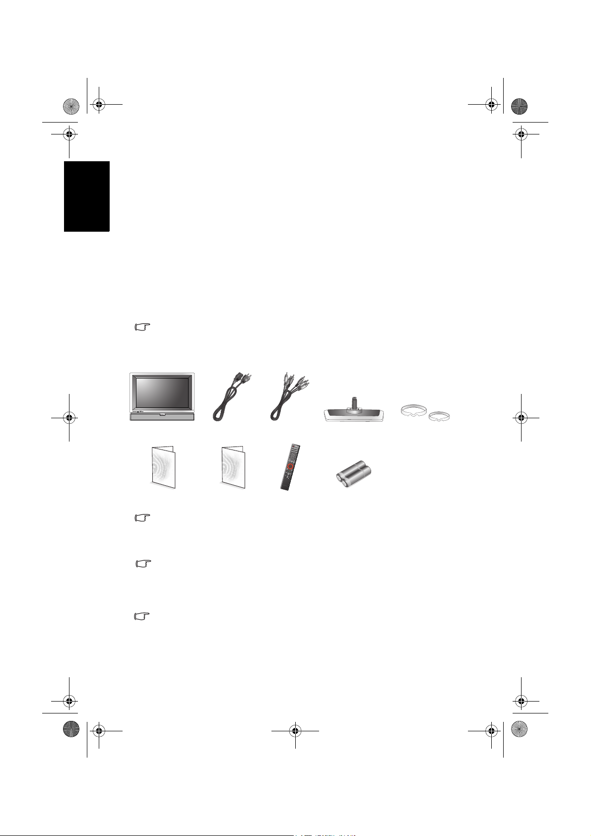
在打開包裝後,請檢查下列所有物品和配件是否齊全:
彩色液晶顯示器 (x1) 電源線 (x1) 複合視訊 (AV)
訊號線 (x1)
快速使用指南 / 使用
手冊 (x1)
本產品所提供的電源線類型可能會隨您購買地點不同而與上圖所示有所差異。
如果有任何物品和配件遺漏或損壞,請馬上與您購買產品的經銷商連
絡,並告訴他們詳細情況。 本使用手冊與參考文件請妥善保存,以方便
隨時參考使用。
如何正確處理產品包裝材料:
• 產品的硬紙板包裝箱 ( 或包裝盒 ) 都是可以回收的。
• 請勿將所有塑膠袋放置在兒童容易拿取的地方。
• 若可能,請妥善收好所有的包裝材料,以方便將來運送本顯示器時使用。
• 在丟棄包裝材料前,請確認沒有遺忘任何的物件在其中。
為了您自身和旁人的安全,在安裝顯示器時一定要小心謹慎,避免損壞顯示器
或對使用的人造成危險。
液晶顯示器的螢幕上有一層很薄的玻璃膜,很容易因為敲擊或壓力而造
成裂痕、劃傷,甚至破裂。 同樣地,在過度的施力或極度的溫差變化
下,特殊的液晶材質同樣也可能會損壞。 因此,請在安裝或使用時都要
特別地小心謹慎。
第一部分: 快速使用指南2
保固服務資訊
(x1)
遙控器 (x1) AAA 四號電池
底座 (x1) 塑膠墊圈 (x2)
(x2)
Page 5
V26B_V32B_TW_TC.book Page 3 Monday, October 29, 2007 5:38 PM
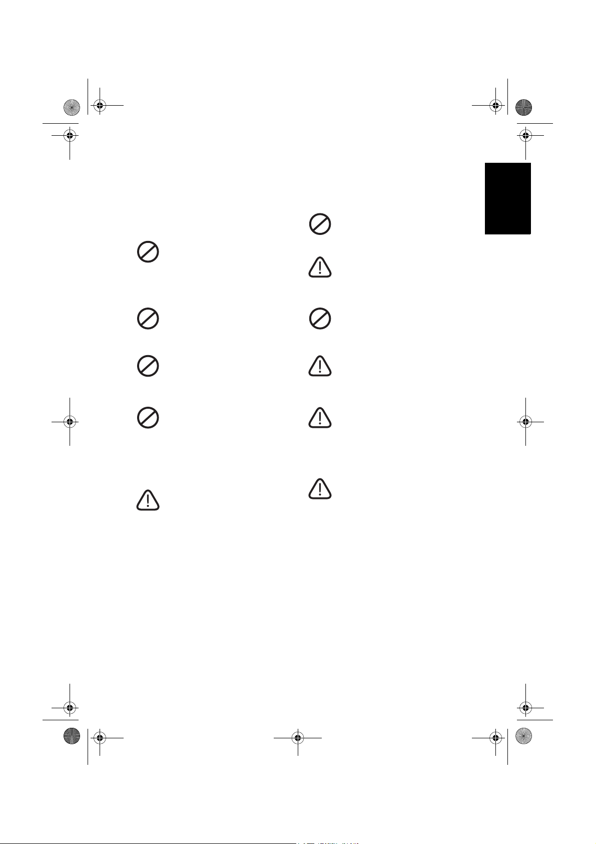
3. 選擇適當的安裝位置
為避免潛在的損害發生並延長顯示器的使用壽命,請在安裝與操作顯示
器時,遵守以下幾點:
請勿將顯示器放置在不穩定、傾
斜或不牢固的平台上,因為可能
會使顯示器掉落,造成顯示器及
人員的嚴重損害。如果可能的
話,建議您委託專業的施工人員
將顯示器固定在置放的位置上,
如此可在萬一地震發生時,防止
顯示器傾倒掉落。
請勿在靠近水的地方使用顯示
器,例如浴池或游泳池,也不要
將顯示器放置在容易被水噴濺的
地方,例如窗戶旁。
請勿將顯示器放置在距離熱源太
近的地方,例如散熱器、電暖
器、暖爐及其它會產生熱氣的產
品 ( 包括音響擴大機 )。
請勿將顯示器放置在陽光或強光
直接照射到的地方,因為過熱的
陽光可能會對顯示器產生損傷,
而強光的直接照射則會影響顯示
內容的觀賞。
若要將本顯示器懸掛於牆壁上使
用,請務必使用本公司專為本產
品型號所提供的壁掛配件, 並確
保壁掛配件裝釘的位置是水平
的。 安裝時,務必請合格專業的
技術人員來幫您安裝,一定要確
認壁掛配件是否已經牢固地深鎖
於牆壁內層上,而不是只有鎖在
牆壁的裝潢薄板上,千萬不要僅
使用任何種類的膠黏在牆壁上。
繁體中文
請勿將顯示器放置在通風不佳的
環境中。
請注意並遵守所有標示在顯示器
上的警告與指示。
當顯示器電源開啟時,請勿覆蓋
或阻塞機體的任何通風口或開
口。 建議您定期清理機身上的通
風口,以保持散熱順暢。
若要將顯示器懸掛於牆壁上使
用,顯示器周圍請保留足夠的空
間,以方便將顯示器順利懸掛於
壁掛配件上。
若要將顯示器採嵌壁式方式內嵌
於牆壁內使用時,顯示器的上下
方請保留足夠的空間,以保持良
好的通風狀態。
本顯示器上沒有可切斷電源供應
的電源開關。在安裝本顯示器
時,請在顯示器與電源插座間加
裝可以切斷電源的開關裝置,或
讓電源插座位於顯示器附近可以
方便接近的地方,以備萬一顯示
器發生故障時,可以迅速切斷電
源,或取下電源插頭。
第一部分: 快速使用指南 3
Page 6
V26B_V32B_TW_TC.book Page 4 Monday, October 29, 2007 5:38 PM
繁體中文
4. 安裝底座
安裝前的注意事項
在開始安裝底座前,請您務必注意下列事項:
• 由於顯示器的重量頗重,因此在安裝底座時,務必由兩人以上之成人
進行安裝。
• 顯示器的液晶面板極為脆弱並且易受損傷。在拿取或移動顯示器本體
時,請手持螢幕邊框,避免觸摸到面板本身,並請注意勿讓任何物體
碰撞到液晶面板。請在安裝時,以一塊柔軟乾淨且不掉棉絮的浴巾包
覆顯示器本體,以保護液晶面板。
• 請將顯示器安裝在堅硬、平坦且穩固的平面上,以免顯示器傾倒造成
危險。如果可能的話,建議您委託專業的施工人員將顯示器固定在置
放的位置上,如此可在萬一地震發生時,防止顯示器傾倒掉落。
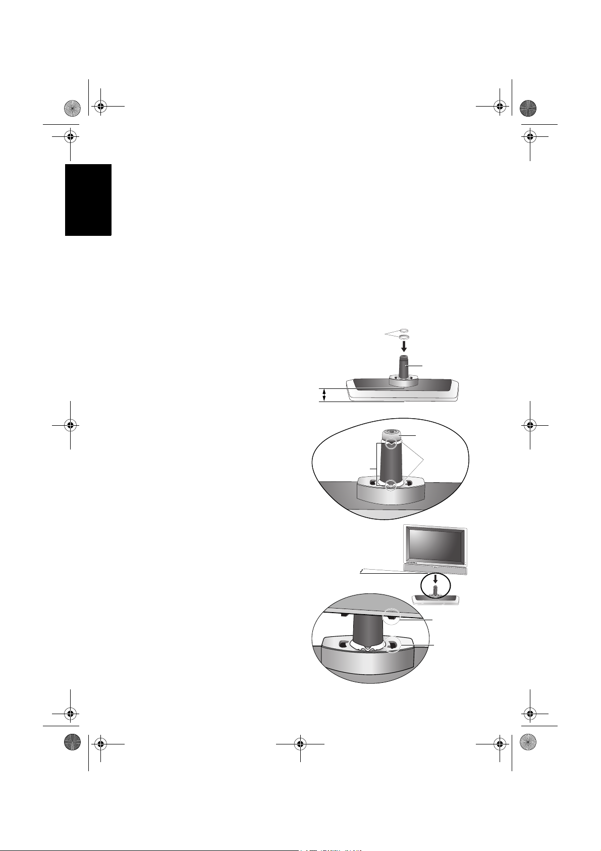
安裝底座
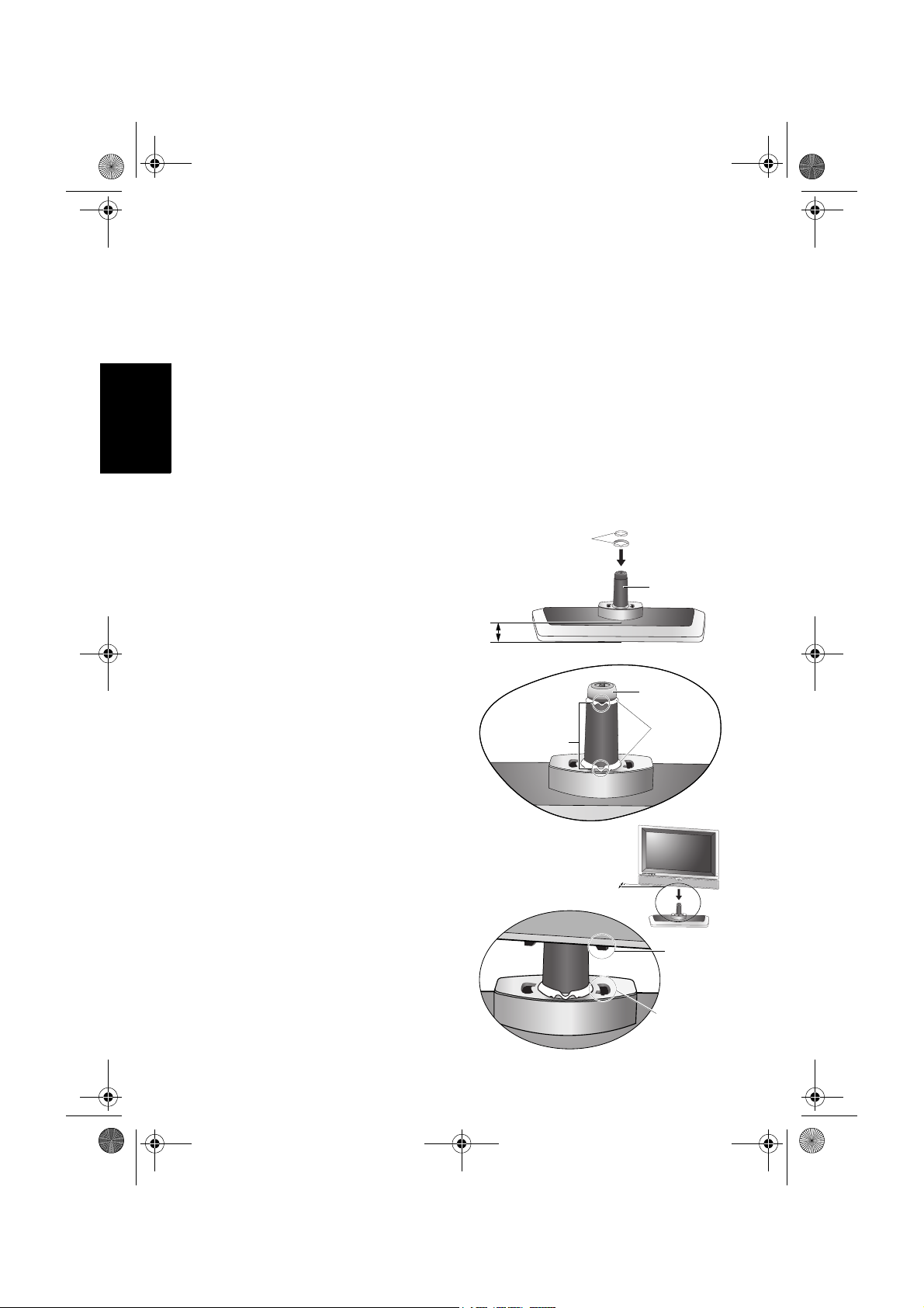
塑膠墊圈
1. 如右圖所示,使底座較寬部份
面向前方,並將兩個塑膠墊圈
套上底座軸。
2. 塑膠墊圈安裝完成後,其位置
應如右圖所示。請特別注意墊
圈上 「V」字形部位的方向,
切勿安裝錯誤。
3. 將顯示器本體抬起,並將顯示
器底部的底座孔對齊底座軸,
然後如右圖所示以約 30 度的角
度套入底座。在套入時,請注
意必須讓顯示器底部的定位柱
對齊底座上的定位孔。
較寬部份面向前方
請特別注意墊圈
上此 「V」字形
部位的方向
o
30
底座軸
底座軸
塑膠墊圈
定位柱
定位孔
第一部分: 快速使用指南4
Page 7
V26B_V32B_TW_TC.book Page 5 Monday, October 29, 2007 5:38 PM
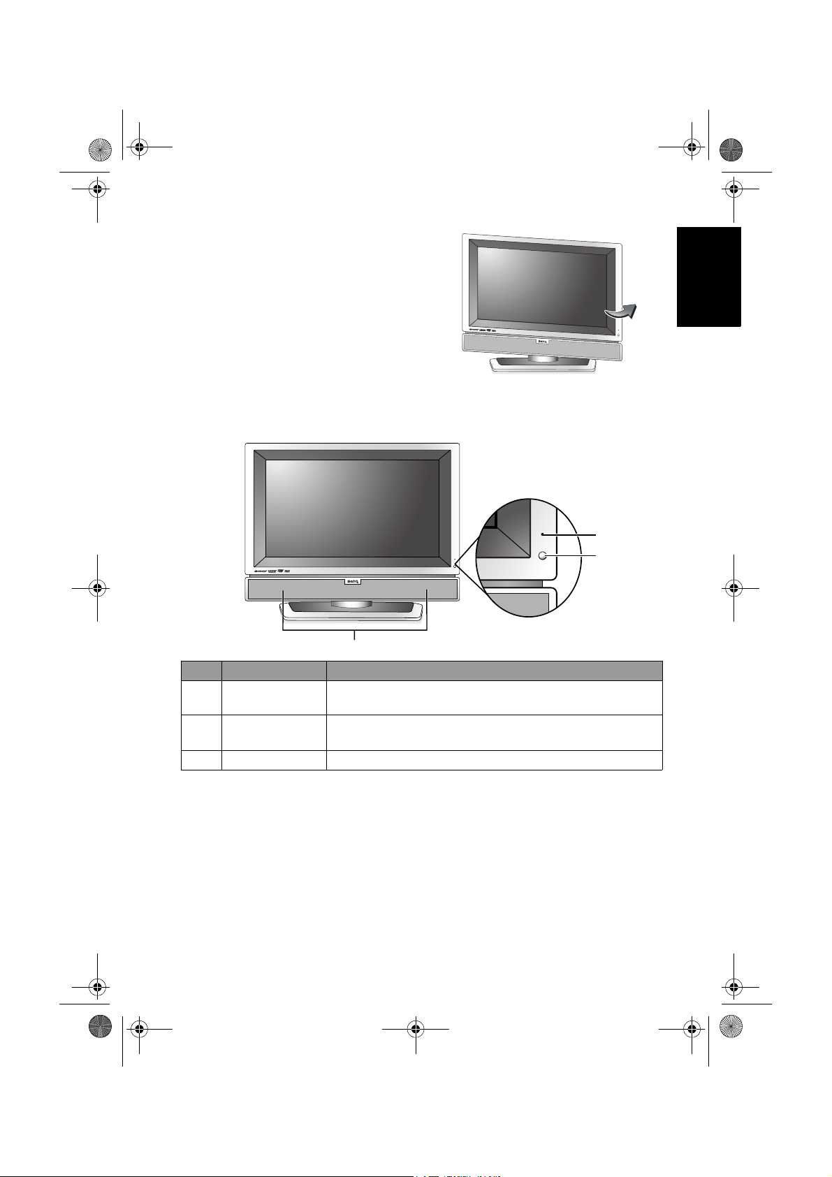
4. 顯示器本體套入底座後,將本
體旋轉面向正前方,安裝即告
完成。
5. 認識您的顯示器
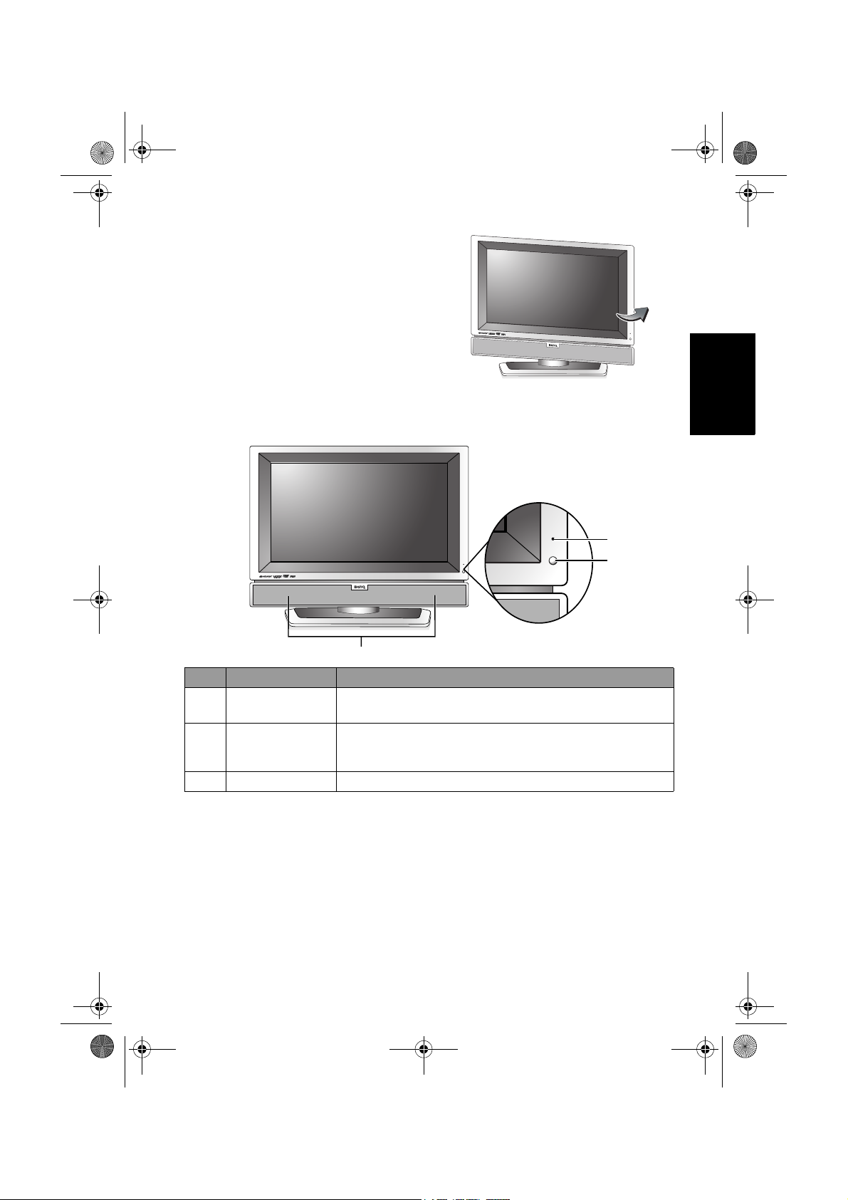
前視圖
繁體中文
1
2
3
編號 名稱 說明
1
電源指示燈
2
遙控訊號感應窗
3
揚聲器 提供高音質且逼真的音效輸出。
• 當顯示器電源開啟時,此指示燈會亮綠色。
• 當顯示器電源處於待機狀態時,此指示燈會亮紅色。
接收從遙控器傳送過來的訊號。 請勿將任何物體放置
於此感應器前方,以避免阻礙訊號的接收。
第一部分: 快速使用指南 5
Page 8
V26B_V32B_TW_TC.book Page 6 Monday, October 29, 2007 5:38 PM
繁體中文
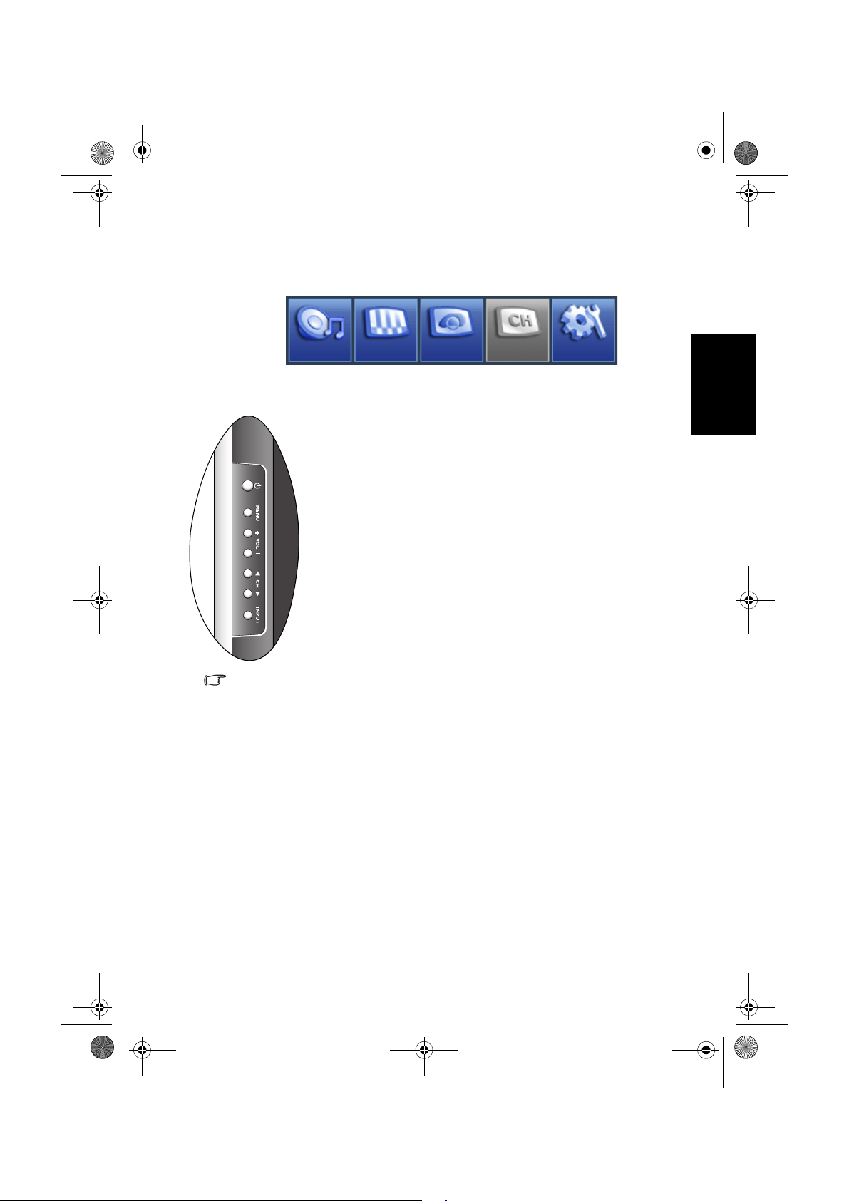
控制面板 ( 右側 )
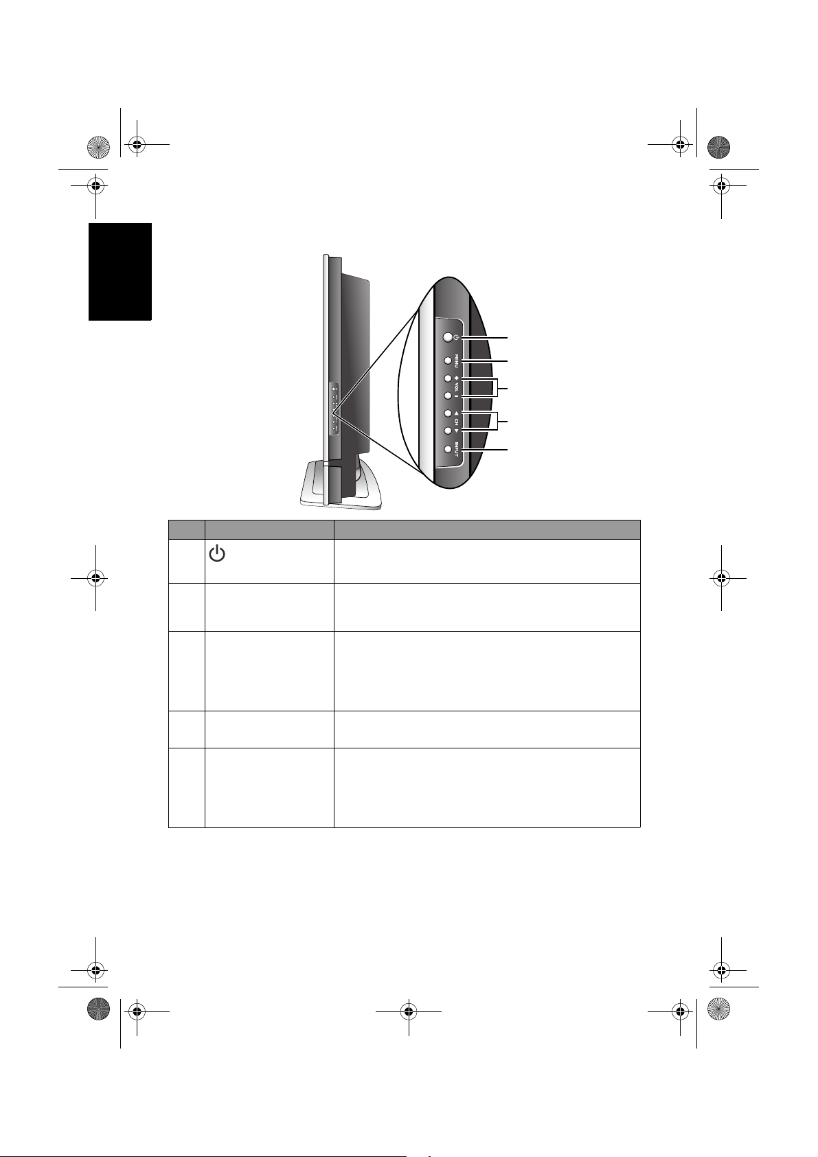
編號 名稱 說明
1
2
3
4
5
( 電源 / 待機 )按鈕按此按鈕可開啟顯示器的電源,或讓顯示器進入
MENU ( 選單 ) 按鈕
VOL ( 音量 ) +/-
按鈕
CH ( 選擇 ) /
按鈕
INPUT ( 輸入選擇 )
按鈕
1
2
3
4
5
待機模式。請參閱第 15 頁的 「開機和待機」。
按下此按鈕可顯示螢幕顯示選單,再按一次此按
鈕可將之關閉。請參閱第 19 頁的 「瀏覽螢幕顯示
選單」。
• 用以調整顯示器之內建揚聲器的音量大小。請參
閱第 15 頁的 「調整音量」。
• 在螢幕顯示選單中,按這些按鈕可進行左右選擇
或變更設定。請參閱第 19 頁的 「瀏覽螢幕顯示
選單」。
在螢幕顯示選單中,按這些按鈕可進行上下選擇。
請參閱第 19 頁的 「瀏覽螢幕顯示選單」。
• 可讓您選擇不同的輸入訊號源。請參閱第 15 頁
的 「切換輸入訊號」。
• 在螢幕顯示選單開啟時,按此按鈕可選擇反白的
功能,或進入子選單 ( 若有的話 )。請參閱第 19
頁的 「瀏覽螢幕顯示選單」。
第一部分: 快速使用指南6
Page 9
V26B_V32B_TW_TC.book Page 7 Monday, October 29, 2007 5:38 PM
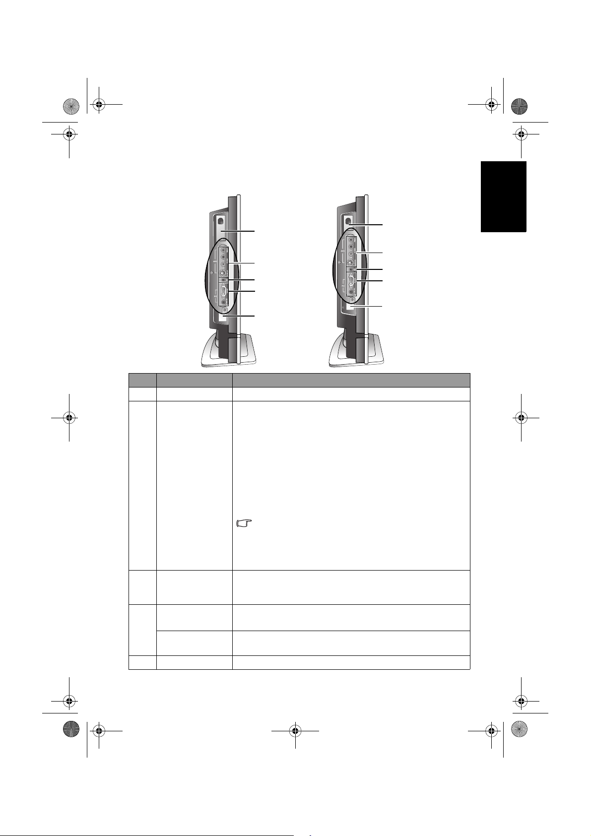
外接視聽裝置端子面板 ( 左側 )
VB2621
1
2
3
4
5
編號 名稱 說明
1
數位視訊盒槽 可供您安裝選購的數位節目視訊盒。
• VIDEO ( 複合視訊 ) 輸入端子:用以連接至視訊來源
裝置的複合視訊輸出端子。請參閱第 10 頁的 「連接
複合視訊輸入」。
• S-VIDEO (S-Video 視訊 ) 輸入端子:用以連接至視訊
來源裝置的 S-Video 輸出端子。 請參閱第 10 頁的
AV 2 輸入端子
2
( 複合視訊或 SVideo)
3
耳機插孔
PC D-SUB ( 電腦
視訊輸入 )
4
PC AUDIO IN (
電腦音訊輸入 )
5
類比視訊盒槽 可供您安裝選購的類比節目視訊盒。
「連接 S-Video 視訊輸入」。
• AUDIO L/R ( 左 / 右聲道音源 ) 輸入端子:用以連接
至視訊來源裝置對應於複合視訊或 S-Video 視訊的左
右聲道音訊輸出端子。請參閱第 10 頁的 「連接複合
視訊輸入」與第 10 頁的 「連接 S-Video 視訊輸入」。
您可以使用複合視訊或 S-Video 視訊的輸入端子來連
接外接的視訊來源裝置。 如果兩組端子同時都已經連
接至視訊來源,那麼顯示器僅會顯示 S-Video 視訊輸
入。 若需選擇其一,建議您 S-Video 所提供的影像畫
質會比較好。
此插孔可讓您外接耳機以提供聲音輸出使用。當外接
耳機一接上時,顯示器內建的揚聲器會立刻變成靜音
狀態,所有聲音改由耳機輸出。
用以連接至電腦的 D-Sub 視訊輸出端子。請參閱第 11
頁的 「連接電腦 D-Sub 視訊輸入」。
用以連接至電腦視訊輸出所對應的音訊輸出端子。請
參閱第 11 頁的 「連接電腦 D-Sub 視訊輸入」。
繁體中文
VB3221
1
2
3
4
5
第一部分: 快速使用指南 7
Page 10
V26B_V32B_TW_TC.book Page 8 Monday, October 29, 2007 5:38 PM
繁體中文
後視圖
VB2621
5
編號 名稱 說明
HDMI /DVI (HDMI/
1
DVI 輸入 )
AV 1 Y C
B/PB CR/PR
(AV 1 色差視訊輸入 )
2
AV 1 L/ R
(AV 1 色差視訊左 / 右
聲道音源輸入 )
AUDIO OUTPUT L/R (
3
左 / 右聲道音源輸出 )
DVI-AUDIO INPUT L/
4
R (DVI 左 / 右聲道輸
入 )
5
AC-INLET ( 電源輸入 )
1
34
2
5
VB3221
4
3
2
用以連接至電腦的 DVI 數位視訊輸出端子,或
視訊來源裝置的 HDMI 數位音訊 / 視訊輸出端
子。請參閱第 12 頁的 「連接 DVI 視訊輸入」
與第 12 頁的 「連接 HDMI 視訊輸入」。
用以連接至視訊來源裝置的色差視訊輸出端子
B/PB CR/PR)。請參閱第 11 頁的 「連接色差
(Y C
視訊輸入」。
用以連接至視訊來源裝置對應於色差視訊輸出
的左 / 右聲道音源輸出端子。請參閱第 11 頁的
「連接色差視訊輸入」。
用以連接至外接音源裝置的左 / 右聲道音源輸入
端子。此輸出端子可在任何時候連接使用。然
而,其輸出音量大小是固定不變的,並無法從
顯示器上調整。請參閱第 13 頁的 「連接立體聲
音源輸出」。
用以連接至電腦的 DVI 視訊輸出所對應的左 /
右聲道音訊輸出端子。請參閱第 12 頁的 「連接
DVI 視訊輸入」。
用以連接電源線。請參閱第 14 頁的 「7. 連接電
源線」。
1
第一部分: 快速使用指南8
Page 11

V26B_V32B_TW_TC.book Page 9 Monday, October 29, 2007 5:38 PM
6. 連接視訊和音源
支援的輸入訊號種類
在本顯示器上有許多類比與圖形視訊輸入端子,以及相對應的音訊輸入
端子 ( 請參閱第 7 頁的 「外接視聽裝置端子面板 ( 左側 )」與第 8 頁的
「後視圖」 ),可支援同時連接數種不同類型的視訊輸入來源,並可讓您
隨時使用顯示器上的 INPUT ( 輸入選擇 ) 按鈕切換想顯示的輸入源:
• 類比視訊源輸入: 包括 1 組 S-Video 視訊輸入端子、 1 組複合視訊 (AV)
輸入端子與 1 組色差視訊輸入端子。
• 圖形視訊源輸入: 包括 1 組 HDMI/DVI 數位視訊輸入端子和 1 組 D-
Sub 電腦視訊輸入端子。
本顯示器並不支援可同時顯示兩種視訊畫面的功能,例如子母畫面功能。
類比視訊源輸入
您可將具備有類比視訊輸出的裝置 ( 例如卡式錄放影機或電視遊樂器 )
連接到顯示器的複合視訊 (AV) 或 S-Video 視訊輸入端子使用,並使用顯
示器上的 INPUT ( 輸入選擇 ) 按鈕選擇 「AV 2 」輸入 ( 複合視訊 ) 或
「AV 2 - S 」輸入 (S-Video 視訊 ) 以觀賞這些視訊輸入畫面。 連接方式請
參閱第 10 頁的 「連接複合視訊輸入」和第 10 頁的 「連接 S-Video 視訊
輸入」。
您也可以將具有色差視訊輸出的裝置 ( 例如 DVD 播放機 ) 的色差視訊
輸出端子連接到顯示器的色差視訊輸入端子,並選擇 「AV 1 」輸入以觀
賞色差視訊輸入畫面。連接方式請參閱第 11 頁的 「連接色差視訊輸
入」。
在以上三種類比視訊源輸入中,色差視訊輸入所提供的畫面品質是最高的。
圖形視訊源輸入
您可將電腦的 D-Sub 視訊輸出連接到顯示器的 D-Sub 電腦視訊輸入端
子。若要獲得更佳的畫質,您可將電腦的 DVI 數位視訊輸出,透過 DVI
轉 HDMI 連接線連接至顯示器的 HDMI/DVI 數位視訊輸入端子。若您
的視訊輸出裝置支援 HDMI 輸出,您也可以將之直接連接至顯示器的
HDMI/DVI 輸入端子使用。 請依據您所連接的視訊種類,使用顯示器上
的 INPUT ( 輸入選擇 ) 按鈕選擇 「PC」、「 DVI」或 「HDMI」輸入以
觀賞這些視訊輸入畫面。 連接方式請參閱第 11 頁的 「連接電腦 D-Sub
視訊輸入」、第 12 頁的 「連接 DVI 視訊輸入」和第 12 頁的 「連接
HDMI 視訊輸入」。
若要充分利用本顯示器的高解析度顯示能力,請將您的視訊輸出設備 ( 例如
DVD 播放機或電腦 ) 的視訊輸出解析度設定為接近或吻合本顯示器之面板解析
度的設定 ( 若視訊輸出設備支援的話 ),例如 720p ( 色差 /HDMI 視訊 ) 或 1360
x 768 ( 電腦 D-Sub/DVI 視訊 ) 的解析度。關於如何設定輸出解析度的相關資
訊,請參考所連接設備的說明文件。
連接輸入訊號時的注意事項:
• 為了安全起見,在連接任何外接裝置前,請務必先關閉顯示器與視訊輸出裝
置的電源。
• 在決定使用的連接方式前,請先熟悉認識顯示器上每個輸入端子孔的位置和
類型。因為若連接方式錯誤,會影響到影像的畫質。
• 連接後請確認所有的接頭和訊號線都已牢牢地連接固定而沒有鬆脫的情況。
繁體中文
第一部分: 快速使用指南 9
Page 12
V26B_V32B_TW_TC.book Page 10 Monday, October 29, 2007 5:38 PM
繁體中文
連接複合視訊輸入
如圖所示,使用包裝內附的複合視訊 (AV)
訊號線,將視訊輸出裝置 ( 例如卡式錄放
影機 ) 的複合視訊 (AV) 輸出端子連接至顯
示器上的複合視訊 (AV2) 黃色 VIDEO ( 視
訊 ) 輸入端子,以及紅色 AUD IO R ( 右聲
道 ) 與白色 AUDIO L ( 左聲道 ) 輸入端子。
若您要觀賞從複合視訊端子輸入的畫面,
請使用顯示器上的 INPUT ( 輸入選擇 ) 按
鈕切換輸入訊號種類至 「AV 2 」。
連接 S-Video 視訊輸入
1. 使用 S-Video 訊號線 ( 需另購 ),將視訊
2. 使用適當的 RCA 規格音訊訊號線 ( 須
若您要觀賞從 S-Video 視訊端子輸入的畫
面,請使用顯示器上的 INPUT ( 輸入選擇
) 按鈕切換輸入訊號種類至 「AV 2 - S 」。
複合視訊輸入是目前最普遍的訊號輸入種
類。然而,此種方式所提供的影像畫質是
最低的。 相較之下,S-Video 輸入提供的
影像畫質較佳。
如果在 AV2 輸入端子上同時連接有複合視
訊與 S-Video 輸入訊號,顯示器將只會顯
示 S-Video 輸入訊號。此時,若您要觀賞
複合視訊輸入,請暫時中斷 S-Video 輸入
的連接。
輸出裝置 ( 例如 DVD 播放機 ) 的 S-
Video 輸出端子連接至位於顯示器上的
AV 2 S- VID EO ( 黑色 ) 輸入端子。 在接
上端子時,請對準訊號線的接頭,以免
將接頭的針腳弄歪。
另購 ) ,將視訊輸出裝置的 S-Video 左
右聲道音訊輸出端子連接至顯示器上對
應的 AV 2 紅色 AUDIO R ( 右聲道 ) 與白
色 AUDIO L ( 左聲道 ) 輸入端子。
您無需同時連接同一視訊輸出裝置的複合
視訊和 S-Video 視訊,只需連接其中之一
即可。若您可選擇的話,請使用 S-Video
代替複合視訊,以獲得較佳的影像畫質。
音訊訊號線
複合視訊 (AV)
訊號線
卡式錄放影機
S-Video
訊號線
DVD
播放機
第一部分: 快速使用指南10
Page 13
V26B_V32B_TW_TC.book Page 11 Monday, October 29, 2007 5:38 PM
連接色差視訊輸入
1. 使用色差視訊訊號線 ( 須另購 ) 將視訊
來源裝置 ( 例如電視遊樂器 ) 的色差視
訊輸出端子連接到顯示器上的 AV1 Y 、
B/PB、CR/PR 端子。連接時請注意接
C
頭與端子的顏色是否相符。
2. 使用適當的 RCA 規格音訊訊號線 ( 須
另購 ) ,將視訊來源裝置的音訊輸出端
子連接到顯示器上對應的 AV 1 紅色 R (
右聲道 ) 與白色 L ( 左聲道 ) 輸入端子。
若您要觀賞從色差視訊端子輸入的畫面,
請使用顯示器上的 INPUT ( 輸入選擇 ) 按
鈕切換輸入訊號種類至 「AV 1 」。
在類比視訊訊號中,色差視訊所提供的影
像品質是最好的。
請確認接頭與端子的顏色相符,因為若連
接錯誤,會導致色彩異常或影像扭曲。
若要得到最佳的顯示效果,請將色差視訊
來源裝置的輸出解析度設為 720p。
關於本顯示器支援的所有色差視訊解析
度,請參閱第 30 頁的 「支援的色差視訊
輸入解析度」。
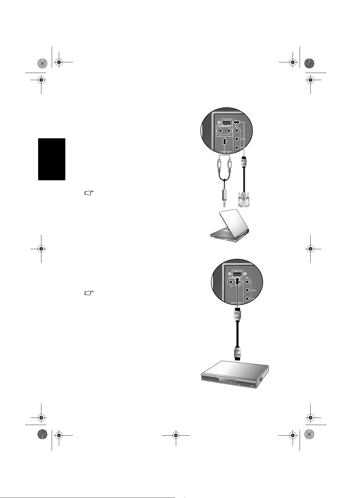
連接電腦 D-Sub 視訊輸入
1. 使用 Mini D-Sub 15 針訊號線 ( 需另購
) ,將電腦 (PC) 的 D-Sub 視訊輸出埠連
接至顯示器的 PC D-SUB ( 電腦視訊 ) 輸
入端子。
2. 使用適當的立體聲音訊訊號線 (3.5mm
Mini-jack 規格,需另購 ) ,將電腦 (PC)
的音源輸出插孔連接至顯示器的 PC
AUDIO ( 電腦音源 ) 輸入端子。
若您要觀賞從電腦視訊端子輸入的畫面,
請使用顯示器上的 INPUT ( 輸入選擇 ) 按
鈕切換輸入訊號種類至 「PC」。
若要得到最佳的顯示效果,請將電腦視訊
輸出設為符合或相近於 1360 x 768 的解
析度 ( 若電腦的顯示卡支援的話 )。
關於本顯示器支援的電腦視訊解析度,以
及如何在電腦上設定適當的輸出解析度,
請參閱第 30 頁的 「支援的電腦視訊 (D-
Sub/DVI) 輸入解析度」與第 31 頁的 「在
PC 上設定適當的電腦視訊輸出解析度」。
音訊訊號
線
音訊訊號線
電腦
色差視訊
訊號線
電視遊樂器
Mini D-Sub
訊號線
繁體中文
第一部分: 快速使用指南 11
Page 14
V26B_V32B_TW_TC.book Page 12 Monday, October 29, 2007 5:38 PM
繁體中文
連接 DVI 視訊輸入
1. 使用適當的 DVI 轉 HDMI 接頭訊號線 (
2. 使用適當的 RCA 規格音訊訊號線 ( 須
3. 在連接完成後,請使用第 26 頁的
若您要觀賞從 HDMI/DVI 端子輸入的 DVI
畫面,請使用顯示器上的 INPUT ( 輸入選
擇 ) 按鈕切換輸入訊號種類至 「DVI」。
連接 HDMI 視訊輸入
使用 HDMI 訊號線 ( 需另購 ) ,將 HDMI
視訊輸出裝置 ( 例如支援的 DVD 播放機
),連接至顯示器的 HDMI/DVI 輸入端子。
若您要觀賞 HDMI 視訊輸入的影像,請使
用顯示器上的 INPUT ( 輸入選擇 ) 按鈕切
換輸入訊號種類至 「HDMI」。
需另購 ) ,將電腦 (PC) 或視訊裝置 ( 例
如 DVD 播放機 ) 的 DVI 視訊輸出埠連
接至顯示器的 HDMI/DVI 輸入端子。
另購 ) ,將電腦或視訊裝置的音源輸出
連接至顯示器的 DVI-AUDIO INPUT 紅
色 R 與白色 L 輸入端子。
「HDMI/DVI 輸入」功能選擇您所連接
的 DVI 視訊類型。
若要得到最佳的電腦視訊顯示效果,請將
電腦視訊輸出設為符合或相近於 1360 x
768 的解析度 ( 若電腦的顯示卡支援的話
)。關於支援的電腦視訊解析度,以及如何
在電腦上設定適當的輸出解析度,請參閱
第 30 頁的 「支援的電腦視訊 (D-Sub/
DVI) 輸入解析度」與第 31 頁的 「在 PC
上設定適當的電腦視訊輸出解析度」。
HDMI ( 高畫質多媒體介面 ) 是一種非壓縮
的數位音訊 / 視訊傳輸介面。它提供視訊
輸出裝置與本顯示器間一個只需連接單一
訊號線的數位音訊 / 視訊傳輸介面。
為確保訊號傳輸的可靠性,建議您使用經
HDMI 認證的高品質 HDMI 訊號線。
請注意,所連接的 HDMI 輸出裝置必須相
容於 HDCP ( 一種針對高畫質數位內容的
防拷保護標準 ) 才能正常顯示。
本顯示器的 HDMI 輸入符合 HDMI 1.2 規
格,且支援最高達 1080i 的解析度。關於
支援的 HDMI 視訊解析度資訊,請參閱第
30 頁的 「支援的 HDMI 輸入解析度」。
音訊訊號線
電腦
HDMI 訊號線
DVI 轉
HDMI 接頭
訊號線
DVD
播放機
第一部分: 快速使用指南12
Page 15
V26B_V32B_TW_TC.book Page 13 Monday, October 29, 2007 5:38 PM
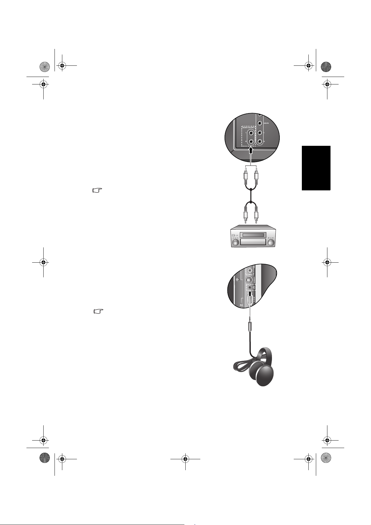
連接立體聲音源輸出
本顯示器提供一組立體聲音訊輸出端子,用
於將音訊訊號輸出至其它音訊設備 ( 例如外
接擴大機或家庭劇院等設備 )。
1. 使用適當的 RCA 規格音訊訊號線 ( 須另
購 ) ,將外接擴大機或其它音響裝置的
左 / 右聲道類比音源輸入端子連接至顯
示器上的 AUDIO OUTPUT L/R ( 左 / 右
聲道音源輸出 ) 端子。
2. 在完成連接後,請將 「聲音」選單中的
「內建揚聲器」項目設為 「關」。
此輸出端子的音量大小是固定不變的,並
無法從顯示器上調整。您必須利用所連接
之音響裝置的音量調整功能進行調整。
連接耳機輸出
本顯示器提供一個耳機輸出插孔,可供您
外接耳機使用。
將耳機的輸入插頭 (3.5mm Mini-jack 規格 )
插入顯示器上的耳機輸出插孔即可。
在連接耳機後,顯示器的揚聲器會馬上變
成靜音狀態。耳機的音量可以使用電視上
的 VOL
( 音量 ) +/- 按鈕調整。
使用耳機時,請調整至適當的音量,並避
免長時間使用,以免損害聽力。
繁體中文
音源線
擴大機
耳機
第一部分: 快速使用指南 13
Page 16
V26B_V32B_TW_TC.book Page 14 Monday, October 29, 2007 5:38 PM
繁體中文
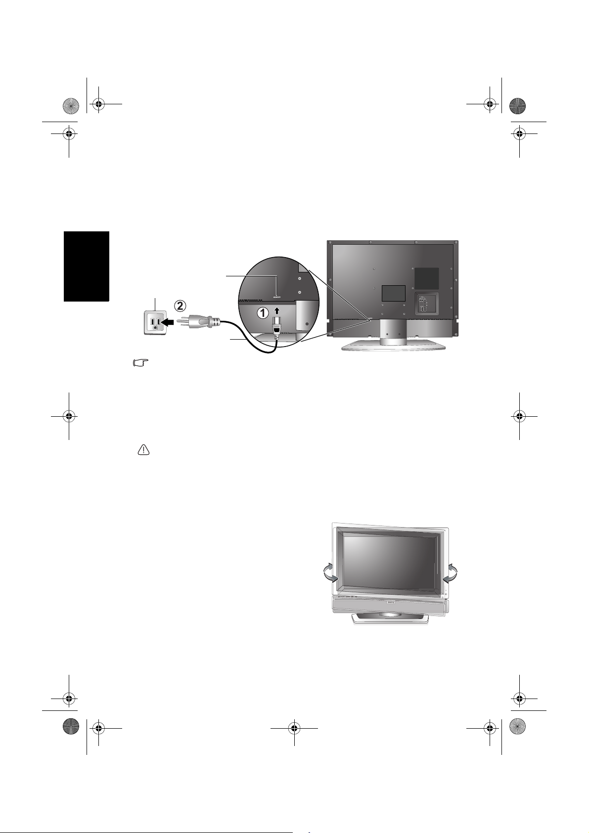
7. 連接電源線
1. 將電源線的一端連接到顯示器後方的 AC-INLET 電源插孔。
2. 將電源線的另一端連接到電源插座上,若電源插座上有電源開關的
話,請打開電源開關。 顯示器將會進入待機狀態,且電源指示燈 (
位於顯示器前方右下角 ) 將會亮紅色。
AC-INLET 電源插孔
電源插座
電源線
• 本顯示器所提供的電源線插頭形狀可能會隨您購買地點不同,而與以上圖示
有所差異。
• 請務必使用符合您當地電源規範的電源線。 若電源線有損壞或磨損,則不可
再繼續使用。 請另購相同規格的電源線替換使用。
• 切勿自行改造電源線的插頭種類。 當使用延長線或多功能插頭插座時,請特
別注意不要超過其負載。
• 本顯示器上沒有可切斷電源供應的電源開關。在安裝本顯示器時,請在顯示
器與電源插座間加裝可以切斷電源的開關裝置,或讓電源插座位於顯示器附
近可以方便接近的地方,以備萬一顯示器發生故障時,可以迅速切斷電源,
或取下電源插頭。
警告: 本顯示器是以最高的安全性為設計和製造原則。然而若不當使用,可能
會有觸電或引發火災的危險。
8. 調整螢幕角度
本顯示器的螢幕可向左或向右水平旋轉約
30 度。您可以依照您的觀賞環境,調整
螢幕至最舒適的觀看角度。
第一部分: 快速使用指南14
Page 17
V26B_V32B_TW_TC.book Page 15 Monday, October 29, 2007 5:38 PM
9. 基本操作
開機和待機
在進行操作前,請確認顯示器的電源線已經插上插座,且插座的電源開關 (如
有開關的話)也已打開。
打開顯示器的電源
將電源線插入電源插座後,顯示器會自動進入待機狀態,且電源指示燈
會亮紅色。按顯示器上的 (電源 / 待機 ) 按鈕。 顯示器將會開機,
且電源指示燈會亮綠色。
讓顯示器進入待機狀態
在顯示器電源開啟的狀態下,按顯示器上的 (電源 / 待機 ) 按鈕,
顯示器將進入待機狀態,且電源指示燈將會亮紅色。
顯示器在待機狀態下仍會消耗少許電力 ( 約 1.5W)。
切換輸入訊號
1. 打開顯示器的電源。
2. 打開視訊來源設備的電源,並播放視訊。
3. 按顯示器上的 INPUT ( 輸入選擇 ) 按鈕切換輸入訊號來源。您可按
下該按鈕數次,直到您想觀賞的輸入畫面顯示在螢幕上為止。 輸入
顯示的順序為:
AV1 ( 色差視訊 )
AV2 ( 或 AV 2-S )
繁體中文
HDMI ( 或 DVI)
PC
• 這些選項僅有在輸入訊號已連接至顯示器上相應的輸入端子時才會出現。
• 如果在顯示器的 AV2 輸入端子上同時連接有複合視訊與 S-Video 輸入訊號,
顯示器將只會顯示 S-Video 輸入訊號。此時,若您要觀賞複合視訊輸入,請
暫時中斷 S-Video 輸入的連接。
• 請注意,HDMI 輸入訊號必須與 HDCP( 一種數位視訊版權標準 ) 相容才能正
常顯示。在切換至 HDMI 輸入時,顯示器會停頓約三秒鐘偵測輸入訊號的
HDCP 資訊,而不會立即顯示畫面。這不是故障。
• 若您要顯示筆記型電腦的畫面,請參照您電腦的使用說明,將視訊輸出從內
建螢幕切換至外接 D-Sub 輸出,方能正常顯示畫面。
調整音量
• 按顯示器上的 VOL ( 音量 ) + 按鈕可增加音量。 螢幕上的音量指示長度
將會增加,代表音量正在增加。
• 按顯示器上的 VOL ( 音量 ) - 按鈕可降低音量。螢幕上的音量指示長度
將會減少,代表音量正在降低。
第一部分: 快速使用指南 15
Page 18

V26B_V32B_TW_TC.book Page 16 Monday, October 29, 2007 5:38 PM
繁體中文
關於維護和清潔顯示器的重要資訊
• 若要清潔顯示器,請務必先讓顯示器進入待機狀態,並中斷與電源插
座的連接。
• 切勿使用任何乳狀、液狀、氣霧式或噴霧式的清潔劑清潔顯示器面
板。 如有必要,請先拿一塊乾淨、不會掉棉絮的軟布,沾上少許 pH
值為中性且已加水稀釋的清潔劑,輕輕地先將面板上的油漬或污垢擦
掉。 接著,再拿另外一塊不會掉棉絮的乾軟布將面板擦拭一遍。
• 本顯示器雖然經過嚴密和特殊環境的測試,您仍然有可能會發現在螢
幕上有極少數失去活性的亮點或暗點會顯示固定的顏色或呈現黑色。
請注意這並不會影響您所購買之產品的效能,因為通常這些亮點或暗
點在正常的觀看距離下是很難看見的。
• 若會有一段長時間不使用顯示器 ( 例如您要出國度假的期間 ) 時,請
務必讓顯示器進入待機狀態,並中斷與電源插座的連接。
• 液晶 (LCD) 螢幕,如同電漿 (PDP) 螢幕或傳統的映像管 (CRT) 螢幕一
樣,都可能在螢幕上產生所謂的 「烙痕」或 「螢幕燒傷」現象。此現
象是指在螢幕上產生肉眼可見的陰影或線條,而無法去除。為了防止
發生此種現象,建議您採取以下的預防措施:
(1) 避免長時間顯示固定不動的影像。
(2) 時常變換各種不同的畫面比例觀賞。
(3) 如果確實有需要長時間顯示靜止畫面,請降低畫面的亮度與對比。
(4) 在顯示電腦輸入訊號時,開啟自動關機省電模式功能 ( 請見第 26
頁的 「省電模式」 )。
接下來 ...
現在您已經閱讀完第一部分 「快速使用指南」的內容。您應該已經了
解如何正確安裝顯示器、連接訊號線、開機 / 待機、選擇輸入源、調整
音量以及維護和清潔等重要工作。 接著,您可以進一步了解這台先進的
顯示器如何為您的生活帶來最大的視聽樂趣。
在第二部分的使用手冊中,我們將詳細地告訴您如何根據您的喜好和使
用的環境需求自訂顯示器設定。 此外,使用手冊中也提供本顯示器的產
品規格和故障排除等資訊,以提供您未來使用時的幫助。
第一部分: 快速使用指南16
Page 19
V26B_V32B_TW_TC.book Page 17 Monday, October 29, 2007 5:38 PM
繁體中文
VB2621/VB3221 彩色液晶顯示器
第二部分: 使用手冊
歡迎使用
Page 20
V26B_V32B_TW_TC.book Page 18 Monday, October 29, 2007 5:38 PM
繁體中文
螢幕顯示選單
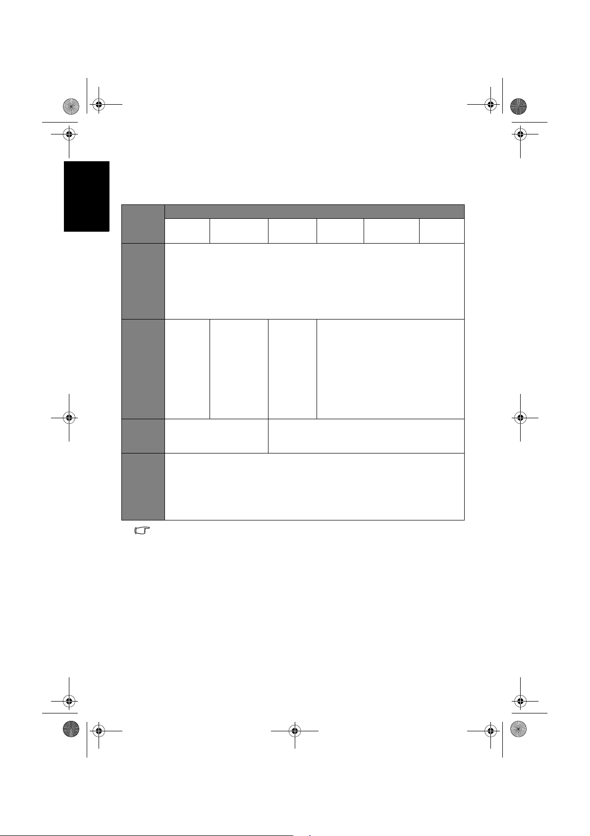
螢幕顯示選單架構
輸入訊號來源
選單項目
聲音
畫質
Senseye
設定
AV 1
• 音量
• 平衡
• 聲音類型
• 穩定音
• 環繞音效
• 內建揚聲器
• 進階設定
• 畫質模式
• 對比度
• 亮度
• 色彩
• 銳利度
• 色溫
• 背光
• 黑階強化
• 自動對比度增強
• 雜訊抑制
• 語言
• 睡眠計時器
• 省電模式
• HDMI/DVI 輸入
• 藍屏模式
• 重回預設值
• 可使用的選單選項會根據您所選擇的輸入訊號來源而定。無法使用的選單選
項將會變成灰色或不顯示。
• 各訊號源下的選單設定是各自獨立的,並不會互相影響。例如在 AV1 訊號源
下的畫質設定並不會影響在 AV2 ( 或 AV 2-S) 訊號源下的畫質設定。
AV2 ( AV 2- S) P C
• 畫質模式
• 對比度
• 亮度
• 色彩
• 銳利度
• 色溫
• 背光
• NTSC 色彩
• NTSC 設定
• 對比度
• 亮度
• 色溫
• 背光
• 自動調整
• 頻率
• 相位
• 水平位置
• 垂直位置
( 無法使用 )
DVI
(PC 訊號 )
• 對比度
• 亮度
• 色溫
• 背光
DVI
(Video 訊號 )
HDMI
螢幕顯示選單18
Page 21
V26B_V32B_TW_TC.book Page 19 Monday, October 29, 2007 5:38 PM
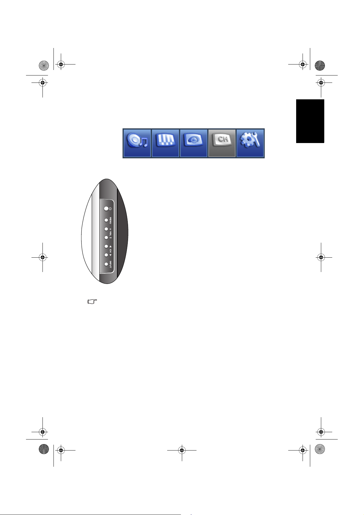
瀏覽螢幕顯示選單
您可以透過螢幕顯示選單調整各種不同的顯示器設定。 按顯示器上的
MENU ( 選單 ) 可顯示螢幕顯示選單 :
聲音
螢幕顯示選單中的操作
• 按顯示器上的 CH ( 選擇 ) 、CH ( 選擇 ) 、VOL (
音量 ) + 或 VOL ( 音量 ) - 可以選取選單中的選項或變
更設定值。
• 按顯示器上的 INPUT ( 輸入選擇 ) 可進入子選單 ( 若有
的話 )。
• 按顯示器上的 MENU ( 選單 ) 可退回上一層選單,或關
閉螢幕顯示選單。
以調整畫面銳利度為例:
1. 按 MENU ( 選單 ) 顯示螢幕顯示選單。
2. 按 VOL ( 音量 ) + 或 VOL ( 音量 ) - 選擇畫質。
3. 按 INPUT ( 輸入選擇 ) 進入子選單。
4. 按 CH ( 選擇 ) 或 CH ( 選擇 ) 選擇銳利度 。
5. 按 VOL ( 音量 ) + 或 VOL ( 音量 ) - 進行調整。
6. 按 MENU ( 選單 )
畫質
Senseye
TV
數次關閉螢幕顯示選單。
繁體中文
設定
請參考本手冊中關於該功能的說明以獲得更詳細的資訊。
請參閱:
• 第 20 頁的 「聲音選單」
• 第 22 頁的 「畫質選單」
• 第 25 頁的 「Senseye 選單」
• 第 26 頁的 「設定選單」
螢幕顯示選單 19
Page 22
10
0
V26B_V32B_TW_TC.book Page 20 Monday, October 29, 2007 5:38 PM
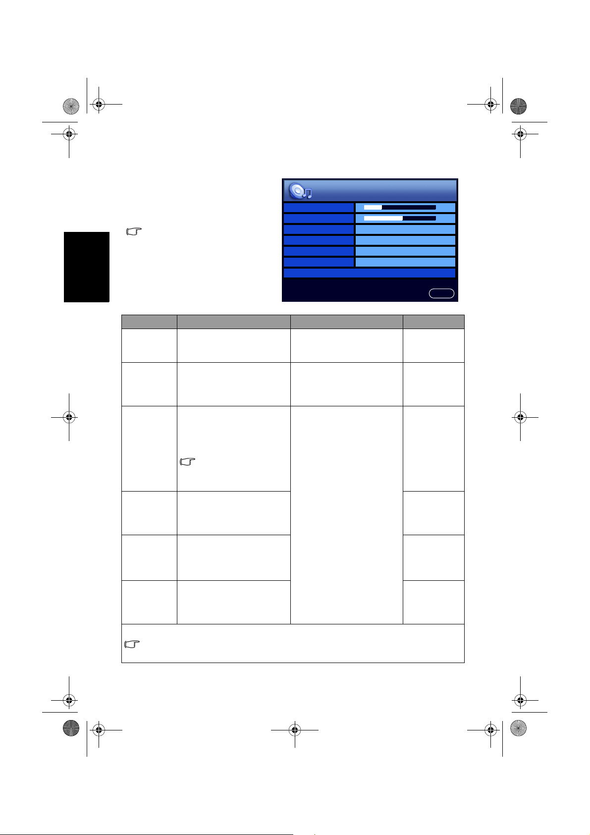
繁體中文
聲音
音量
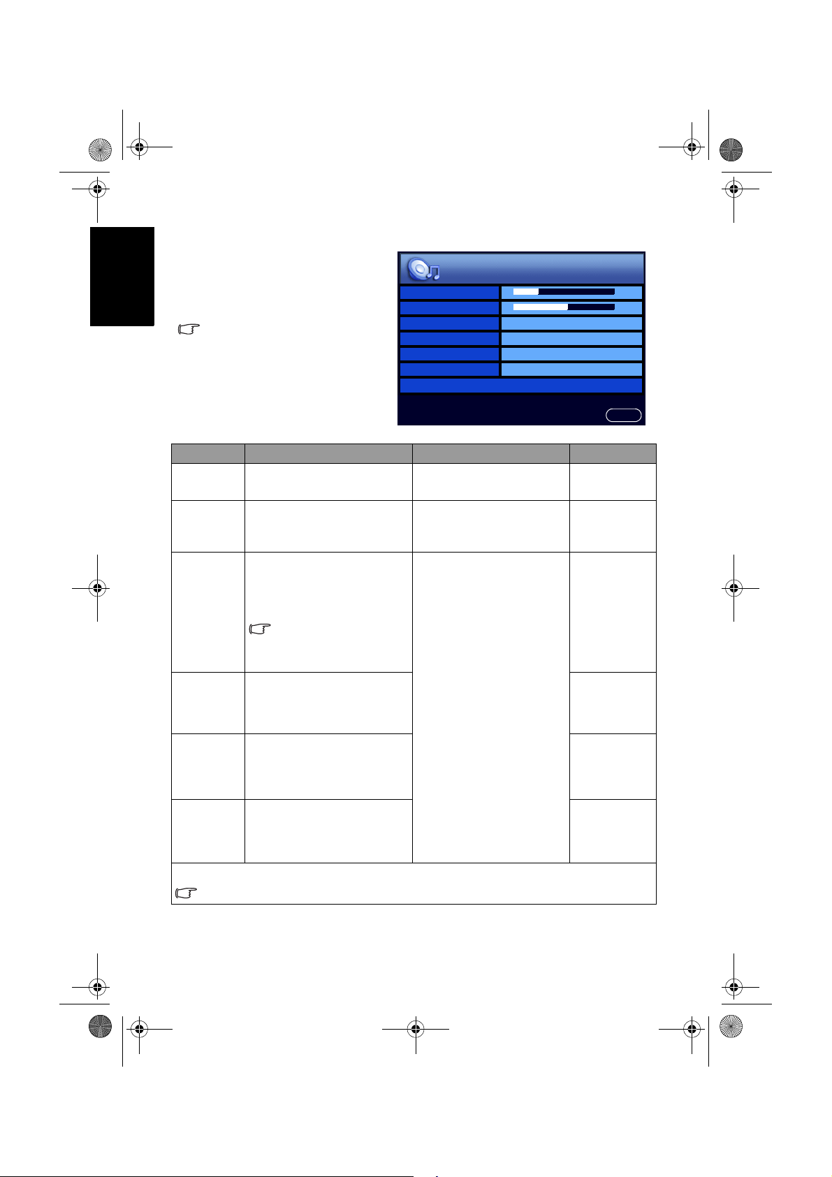
聲音選單
選單中顯示的選項會因為輸入訊
號的種類不同而異。
右圖所示的選單選項與設定僅供
參考。
選項 功能 操作 範圍
音量
平衡
聲音類型
穩定音
環繞音效
內建揚聲器
進階設定 - 按 INPUT 進入子選單。
若 「環繞音效」項目設為 「SRS TruSurround XT」,則本項目將無法使用。
調整顯示器之內建揚聲器
的音量大小。
調整顯示器之內建揚聲器
的左右音量平衡。
當您欣賞的節目或影片支
援多重聲道或多國語言播
送時,您可以使用本功能
來選擇想要的聲音類型。
可選擇的選項將依所接
收的輸入視訊或節目的
音訊格式是否支援而定。
若設為 「自動」,在觀賞
節目時,本功能可自動調
整不同頻道間的聲音大小,
使其達到一致。
開啟或關閉顯示器的 SRS
TruSurround XT 環繞音效。
若設為 「開」,聲音將從
顯示器內建的揚聲器輸出。
若您有外接音響系統時,
可設為 「關」。
平衡
聲音類型 立體聲
穩定音 關
環繞音效 關
內建揚聲器 開
進階設定 >
按 VOL + 增加音量,或
按 VOL - 降低音量。
按 VOL + 增加右揚聲器
音量,或按 VOL - 增加左
揚聲器音量。
按 VOL + 或 VOL - 選擇。
回上頁
0 到 47
-12 到 12
• 立體聲
• 單聲道
• 副語
• 左聲道
• 右聲道
• 聲音一
• 聲音二
• 自動
• 關
• SRS
TruSurround
XT
• 關
• 開
• 關
螢幕顯示選單20
Page 23

V26B_V32B_TW_TC.book Page 21 Monday, October 29, 2007 5:38 PM
音效模式
高音
中高音
中音
中低音
低音
選擇一種預設的音效模式,
或選擇自訂,讓您自行調
整喜好的音效模式。
當音效模式設定為 「自
訂」時,調整高音音調。
當音效模式設定為 「自
訂」時,調整中高音音調。
當音效模式設定為 「自
訂」時,調整中音音調。
當音效模式設定為 「自
訂」時,調整中低音音調。
當音效模式設定為 「自
訂」時,調整低音音調。
設定音效模式中的 「自訂」模式
1. 按顯示器上的 MENU 顯示螢幕顯示選單。
2. 按 VOL + 或 VOL - 選擇聲音,然後按 INPUT 進入聲音選單。
3. 按 CH 或 CH 選擇進階設定,然後按 INPUT 進入進階設定選
單。
4. 按 CH 或 CH 選擇音效模式,然後按 VOL + 或 VOL - 選擇自
訂。
5. 按 CH 或 CH 選擇高音、中高音、中音、中低音、低音等設定,
然後按 VOL + 或 VOL - 調整至您滿意的效果。
6. 按 MENU 關閉螢幕顯示選單並儲存。
按 VOL + 或 VOL - 選擇。
按 VOL + 或 VOL - 進行
調整。
• 搖滾樂
• 爵士樂
• 古典
• 流行樂
• 自訂
-12 到 12
繁體中文
螢幕顯示選單 21
Page 24

32
32
32
4
6
32
V26B_V32B_TW_TC.book Page 22 Monday, October 29, 2007 5:38 PM
繁體中文
畫質
畫質模式
畫質選單
選單中顯示的選項會因為輸入訊
號的種類不同而異。
右圖所示的選單選項與設定僅供
參考。
對比度
亮度
色彩
銳利度
色溫 一般
背光
NTSC 色彩
NTSC 設定
7.5 IRE
選項 功能 操作 範圍
您可依照您的收視環境,使
用顯示器預設的畫質模式,
使畫面的呈現最佳化,或自
行設定您喜愛的畫質模式。
畫質模式
若您選擇了 「自訂」,您可
針對您的喜好個別調整對比
度、亮度、色彩和銳利度等
設定。
關於各種畫質模式使用的時
機,以及如何設定 「自訂」
按 VOL + 或 VOL -
選擇。
• 標準
• 劇院
• 動態
• 遊戲
• 自訂
模式,請參閱第 24 頁的
「各種畫質模式使用的時機」
與 「設定畫質模式中的 「自
訂」模式」的說明。
對比度
亮度
當畫質模式設定為 「自訂」
模式時,用以調整影像的對
比度 ( 請參閱第 24 頁的 「調
整對比度」 )。
當畫質模式設定為 「自訂」
模式時,用以調整影像的亮
度 ( 請參閱第 24 頁的 「調整
亮度」 )。
按 VOL + 可將白
色調部分調亮
,
按
VOL - 可將白色調
部分調暗。
按 VOL + 可將黑
色調部分調亮
,
按
VOL - 可將黑色調
部分調暗。
0 到 64
當畫質模式設定為 「自訂」
按 VOL + 可調高
,
色彩的飽和度
按
VOL - 可調低色彩
的飽和度。
色彩
模式時,用以調整影像的色
彩飽和度。
飽和度亦即色彩的純度,純
度愈高,表現愈鮮明,純度
愈低,表現則愈黯淡。
標準
回上頁
螢幕顯示選單22
Page 25

V26B_V32B_TW_TC.book Page 23 Monday, October 29, 2007 5:38 PM
當畫質模式設定為 「自訂」
模式時,用以調整影像的銳
利度。
調整銳利度的目的是為了補
銳利度
償影像訊號轉換時損失的細
節,而加入高頻訊號讓影像
更鮮明。若銳利度太高,會
使線條太僵硬且產生高頻的
雜訊。因此調整時請注意不
要讓雜訊出現即可。
色溫 調整影像色溫。
背光
調整液晶螢幕面板的背光亮
度。
調整 NTSC 格式視訊的色
NTSC 色彩
調。
本選項僅適用於 NTSC 格
式的視訊。
設定顯示器所顯示的 NTSC
視訊類型,使其與視訊來源
設備 ( 例如 DVD 播放機等 )
NTSC 設定
所輸出的 NTSC 視訊類型相
符。
本選項僅適用於 NTSC 格
式的視訊。
讓顯示器自動調整 PC 輸入
自動調整
畫面的頻率、相位、水平位
置與垂直位置。
頻率 手動調整 PC 輸入畫面的時
相位
脈頻率與相位,使畫面清晰
而沒有抖動的情形。
水平位置 手動調整 PC 輸入畫面的水
垂直位置
平與垂直位置,使畫面顯示
在螢幕的正中央。
按 VOL + 可使影
像看起來更銳利
按 VOL - 可使影像
,
0 到 6
看起來較不銳利。
• 暖
按 VOL + 或 VOL -
進行調整。
• 一般
• 冷
0 到 10
按 VOL + 可使色
調偏紅
,
按 VOL -
0 到 64
可使色調偏綠。
按 VOL + 或 VOL -
選擇。
• 0 IRE
• 7.5 IRE
按 INPUT 執行自動調整功能。
按 VOL + 或 VOL -
選擇。
( 依照輸入視訊
的解析度而異 )
繁體中文
螢幕顯示選單 23
Page 26

V26B_V32B_TW_TC.book Page 24 Monday, October 29, 2007 5:38 PM
繁體中文
各種畫質模式使用的時機
調整對比度
調整亮度
您可以依照您觀賞視訊畫面時的周圍環境,選擇一種適合的畫質模式:
畫質模式 說明
標準 適合在一般環境下觀賞視訊畫面時使用。
劇院
動態
遊戲
自訂
1. 先將對比度調到最高,再往下調整。
2. 在調整過程中,使亮部細節 ( 如大理石上的紋理 ) 由全白中慢慢浮
現,直到細節不再出現之對比最高值,即為最佳對比。如再降低,
亮部過暗,顏色飽和度及立體感則會消失。
1. 先將亮度調到最低,再往上調整。
2. 在調整過程中,使暗部細節 ( 如主播黑西裝上的紋理 ) 慢慢浮現,
直到細節不再出現之亮度最低值,即為最佳亮度。如再提高,黑色
會轉為偏灰白色,亮度即過亮。
適合在較暗的環境下觀賞視訊畫面時使用。畫面的對比度
會被降低,以適合較暗的環境。
適合在較亮的環境下觀賞視訊畫面時使用。畫面的對比度
會被提高,以適合較亮的環境。
畫面的亮度與對比度適中,適合長時間觀賞電視畫面時使
用。
選擇使用您所設定的使用者模式 ( 參照下述的 「設定畫
質模式中的 「自訂」模式」 )。
設定畫質模式中的 「自訂」模式
1. 按顯示器上的 MENU 顯示螢幕顯示選單。
2. 按 VOL + 或 VOL - 選擇畫質,然後按 INPUT 進入畫質選單。
3. 按 CH 或 CH 選擇畫質模式,然後按 VOL + 或 VOL - 選擇自
訂。
4. 按 CH 或 CH 選擇對比度、亮度、色彩、銳利度等設定,然後
按 VOL + 或 VOL - 調整至您滿意的狀態。
5. 按 MENU 關閉螢幕顯示選單並儲存。
螢幕顯示選單24
Page 27

V26B_V32B_TW_TC.book Page 25 Monday, October 29, 2007 5:38 PM
Senseye 選單
選單中顯示的選項會因為輸入訊
號的種類不同而異。
右圖所示的選單選項與設定僅供
參考。
選項 功能 操作 範圍
當觀看比較暗的影像時,
可加強影像細節的對比度。
黑階強化
當「 自動對比度增強 」
功能設定為 「低」、
「中」或 「高」時,本選
項將無法使用。
本功能可自動依據影像輸
自動對比度增強
入的訊號增強影像對比度,
使影像對比度最佳化。
本功能可幫助去除影像中
的雜訊。
雜訊抑制
本功能支援來自 AV1 與
AV2( AV2-S) 輸入的畫
面,並且僅支援最高到
480i 或 576i 的解析度。
黑階強化 低
自動對比度增強 關
雜訊抑制 低
按 VOL + 或 VOL -
選擇。
繁體中文
回上頁
• 低
• 中
• 高
• 關
• 低
• 中
• 高
• 關
• 低
• 中
• 高
• 關
螢幕顯示選單 25
Page 28

V26B_V32B_TW_TC.book Page 26 Monday, October 29, 2007 5:38 PM
繁體中文
設定
設定選單
選單中顯示的選項會因為輸入訊
號的種類不同而異。
右圖所示的選單選項與設定僅供
參考。
選項 功能 操作 範圍
語言 選擇螢幕顯示選單的語言。
設定顯示器的預設自動關機時間。
在設定後,此處會顯示到關機前
所剩餘的時間。
睡眠計時器
省電模式
HDMI/DVI
輸入
藍屏模式
重回預設值
在到達關機時間前一分鐘,螢幕
上會出現提示。此時您可按遙控
器上的任何鍵取消定時關機功能。
一但到達設定的時間,顯示器會
自動進入待機模式。
若設定為 「開」:
• 在顯示器偵測不到電腦輸入訊號
超過 5 秒鐘時,會自動進入省電
模式。
• 在顯示器偵測不到其它視訊輸入
訊號超過 10 分鐘時,會自動進
入待機模式。
選擇 DVI 視訊輸入的訊號類型。
例如,若您連接的是電腦,請選
擇「PC 訊號」,若您連接的是視
訊設備 ( 如 DVD 播放機等 ),請
選擇 「Video 訊號」。
若設定為 「開」,則顯示器會在
偵測不到輸入訊號時,自動顯示
全藍色畫面。
重設所有設定並還原回出廠的預
設值。
語言 繁體中文
睡眠計時器 關
省電模式 關
HDMI/DVI 輸入 PC 訊號
藍屏模式
重回預設值
按 VOL + 或 VOL -
選擇。
按 INPUT 以執行本功能。
關
回上頁
• English
• 繁中
關 , 15, 30,
45, 60, 90,
120( 分鐘 )
• 關
• 開
• PC 訊號
• Video 訊號
• 關
• 開
螢幕顯示選單26
Page 29

V26B_V32B_TW_TC.book Page 27 Monday, October 29, 2007 5:38 PM
參考資訊
免責聲明
明基電通股份有限公司不對於此使用手冊的相關內容、適銷性或適合於
某特定目的保證,作出任何明示或暗示的陳述或擔保。此外,本公司保
留修訂本出版品的權利,內容如有變更,恕不另行通知。
版權聲明
明基電通股份有限公司 2007 年版權所有,並保留所有權利。未經本公
司書面許可,不得以任何形式或以電子、印刷、磁學、光學、化學、人
工等其它方式複製、傳播、轉錄本使用手冊的任何部分,也不得將任何
部分儲存至檢索系統中或翻譯成任何語言或電腦語言。
尺寸圖
VB2621
繁體中文
是 SRS Labs, Inc. 的註冊商標。本產品已獲 SRS Labs, Inc. 授
權使用 SRS TruSurround XT 技術。
單位:mm
參考資訊 27
Page 30

V26B_V32B_TW_TC.book Page 28 Monday, October 29, 2007 5:38 PM
繁體中文
VB3221
單位:mm
參考資訊28
Page 31

V26B_V32B_TW_TC.book Page 29 Monday, October 29, 2007 5:38 PM
規格
機型
重量
尺寸 ( 寬 ×
高 × 深 )
含底座
不含底座
含底座
不含底座
畫面尺寸 ( 概略值 ) 26 英吋 32 英吋
畫面比例
液晶面板解析度
液晶面板亮度 ( 典型值 )
液晶面板對比度 ( 典型值 )
可視角度 ( 左 / 右 / 上 / 下 )
反應時間 (Gray to Gray) 8 毫秒 6.5 毫秒
揚聲器
訊號輸入
訊號輸出
電源供應
消耗功率
操作溫度
儲存溫度
視訊系統
遙控器型號標示於遙控器的
電池室內
上述規格如有變更,恕不另行通知。
VB2621 VB3221
11.68 Kg 15.04 Kg
10.98 Kg 14.34 Kg
725.6 × 579.7 × 220 mm 845.2 × 655.3× 220 mm
725.6 × 553.1 × 105.7 mm 845.2 × 598.2 × 114 mm
16:9
1366 × 768
2
500 cd/m
800:1 1500:1
°°°° °°°°
80 /80 /80 /80 89 /89 /89 /89
8W × 2,80Hz ~ 20KHz
• 複合視訊 (AV) × 1
• S-Video × 1
• S-Video/ 複合視訊音源 × 1
• 色差視訊 (Y C
B/PB CR/PR) × 1
• 色差視訊音源 × 1
• HDMI/DVI × 1
• DVI 音源 × 1
• PC D-Sub × 1
• PC 音源 × 1
• 耳機音源輸出 × 1
• 立體聲音源輸出 × 1
AC 100 - 240V,50/60 Hz
120W 160W
0~40 (於海平面高度 )
°C °C
-20 ~ 50 ( 於海平面高度 )
°C °C
支援 NTSC/PAL/SECAM 影片視訊格式
RC-H072
繁體中文
參考資訊 29
Page 32
V26B_V32B_TW_TC.book Page 30 Monday, October 29, 2007 5:38 PM
繁體中文
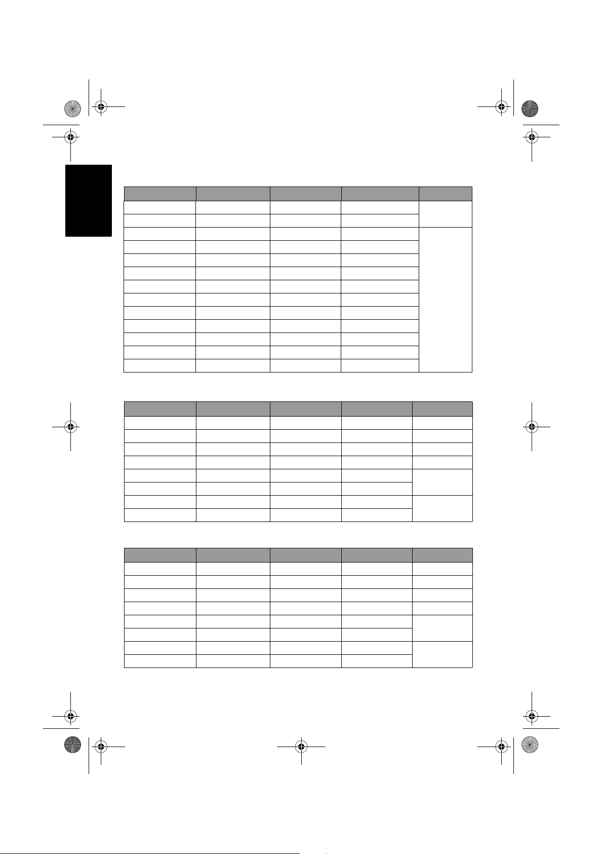
支援的電腦視訊 (D-Sub/DVI) 輸入解析度
解析度 水平頻率 (KHz) 垂直頻率 (Hz) 頻寬 (MHz) 備註
720 × 400 31.47 70.08 28.322
640 × 480 31.5 60 25.18
640 × 480 37.5 75 31.5
640 × 480 37.86 72.81 31.5
800 × 600 37.9 60.32 40
800 × 600 46.9 75 49.5
800 × 600 48.08 72.19 50
1024 × 768 48.4 60 65
1024 × 768 56.5 70 75
1024 × 768 60.023 75 78.75
1280 × 768 47.8 60 79.5
1280 × 768 60.3 75 102.25
1360 × 768 47.7 60 85.5
支援的色差視訊輸入解析度
DOS
VESA
解析度 水平頻率 (KHz) 垂直頻率 (Hz) 頻寬 (MHz) 備註
720 × 480i 15.735 60i 13.5 SDTV 480i
720 × 480p 31.25 60p 27 EDTV 480p
720 × 576i 15.625 50i 13.5 EDTV 576i
720 × 576p 31.25 50p 27 EDTV 576p
1280 × 720p 45 60p 74.25
1280 × 720p 37.5 50p 74.25
1920 × 1080i 33.75 60i 74.25
1920 × 1080i 28.13 50i 74.25
HDTV720p
HDTV1080i
支援的 HDMI 輸入解析度
解析度 水平頻率 (KHz) 垂直頻率 (Hz) 頻寬 (MHz) 備註
720 × 480i 15.735 60i 27 SDTV 480i
720 × 480p 31.47 60p 74.25 EDTV 480p
720 × 576i 15.625 50i 27 EDTV 576i
720 × 576p 31.25 50p 74.25 EDTV 576p
1280 × 720p 45 60p 74.25
1280 × 720p 37.5 50p 74.25
1920 × 1080i 28.13 50i 74.25
1920 × 1080i 33.75 60i 74.25
參考資訊30
HDTV720p
HDTV1080i
Page 33
V26B_V32B_TW_TC.fm Page 31 Wednesday, October 31, 2007 11:19 AM
• 本顯示器僅支援以上表格中所列出的輸入訊號解析度。
• 若要得到最佳的電腦視訊顯示效果,請將電腦視訊輸出設為符合或相近於
1360 x 768 的解析度 ( 若電腦的顯示卡支援的話 )。
• 若在顯示電腦輸入視訊時,畫面會跳動或字體會閃動,請使用 「畫質」選單
中的 「自動調整」功能來重新校正影像。請參閱第 23 頁的 「自動調整」。
在 PC 上設定適當的電腦視訊輸出解析度
若您需要將電腦 (PC) 視訊輸出連接到本顯示器上使用,請先依照下列
說明 ( 以在 Windows XP 作業系統中的設定為例 ) 在 PC 上設定適當的
輸出解析度:
1. 在 Windows 的桌面上按一下滑鼠右鍵,然後從出現的選單中選擇內
容。
2. 在接著出現的視窗中,按一下設定值標籤。
3. 拖曳螢幕解析度滑棒,根據第 30 頁的 「支援的電腦視訊 (D-Sub/
DVI) 輸入解析度」選擇相容的解析度 ( 若您電腦的顯示卡支援,請
將之設為 1360 x 768 的解析度 )。
4. 按確定按鈕儲存設定並關閉視窗。
5. 參照電腦使用手冊的說明,將畫面切換至外接視訊輸出。
6. 按顯示器上的 INPUT 切換至您所要使用的 PC 輸入訊號。
疑難排解
若您在使用本液晶顯示器時遇到困難和問題,在您撥打電話求助於 BenQ 客戶
服務中心之前,請先詳細閱讀下列資訊,看看是否可以自行解決問題,以節省
您的時間。
問題 可能的解決方法
• 打開電源插座上的主開關 ( 若有的話 )。
• 確認電源插頭是否有牢固地插入顯示器的 AC-INLET
無法開啟電源
沒有影像或聲音
影像扭曲
電源輸入和電源插座中。
• 確認電源插座是通電的狀態。如果無法確認電源插
座是否有通電,請試試將其它的電器,例如桌燈,
插上該電源插座看看是否正常。
• 請先確認顯示器電源已開啟 ( 顯示器的電源指示燈應
亮綠色 )。
• 嘗試使用其它的訊號輸入,檢查是否為訊號來源裝
置故障。
• 檢查訊號線的連接方式是否有誤。
• 請檢查音量是否被設定為最小音量或靜音。
• 請檢查 「聲音」選單中,「內建揚聲器」選項是否
被設定為 「關」。 若是,請將之設為 「開」。
• 若您將顯示器連接至電腦,請確認您已將電腦的顯
示模式切換至外接顯示輸出,且電腦未進入待機或
休眠模式。
請確認顯示器的畫面比例是否已正確設定為適合影像
來源的模式。
繁體中文
參考資訊 31
Page 34

V26B_V32B_TW_TC.fm Page 32 Wednesday, October 31, 2007 11:19 AM
繁體中文
訊號線連接正確,但沒
有影像或有聲無影
影像看起來顏色太淡,
或是影像最暗的部分看
起來太亮
電腦視訊顯示異常或不
顯示
遙控器沒有作用
• 請確認訊號線是否連接牢固。
• 請依照您所連接的訊號來源類型,參閱第 30 頁的
「支援的電腦視訊 (D-Sub/DVI) 輸入解析度」、「支
援的色差視訊輸入解析度」或 「支援的 HDMI 輸入
解析度」,確認來自訊號來源設備 ( 例如電腦或電視
遊樂器等 ) 的影像訊號解析度是否符合本顯示器所
支援的解析度。若輸入的影像訊號解析度過高或不
被支援,本顯示器將無法顯示 ( 本顯示器所支援的
最高 HDMI/ 色差視訊影像解析度為 1080i,最高 PC/
DVI 視訊影像解析度為 1360 × 768 @ 60Hz )。此時,
若訊號來源設備提供輸出影像訊號解析度調整的功
能,請降低輸出解析度,或將之調整為本顯示器所
支援的解析度後再試一次。
• 請降低對比度。
• 可能是外接視訊輸出裝置的影像輸出品質設定過高,
請降低訊號輸出品質後再試一次。
• 可能是在與外接視訊輸出裝置的訊號傳輸過程中,
某些視訊訊號被中斷。請檢查訊號線是否有鬆脫。
• 降低螢幕亮度,直到影像中應為暗色的區域顯示正
常。
• 可能是外接視訊輸出裝置的亮度設定過高,請降低
亮度後再試一次。
• 請確認連接的訊號線是否有鬆脫。
• 可能是電腦所輸出的視訊訊號解析度不符本顯示器
所支援的解析度。請參閱第 30 頁的 「支援的電腦視
訊 (D-Sub/DVI) 輸入解析度」與第 31 頁的 「在 PC
上設定適當的電腦視訊輸出解析度」在電腦上設定
相容的輸出解析度,然後再試一次。
• 電腦視訊輸出訊號解析度設定過高,導致本顯示器
無法顯示。1360 × 768 @ 60Hz 是顯示器支援的最高
電腦視訊解析度。
• 若畫面顯示有模糊與跳動情形,請使用 「畫質」選
單中的 「自動調整」功能讓顯示器自動調整設定。
• 請檢查電池安裝的方向是否正確。
• 請檢查電池電源是否已經耗盡。
• 請檢查遙控器與顯示器間的距離和角度是否恰當。
• 請檢查遙控器是否有瞄準顯示器的遙控訊號感應窗。
• 請檢查遙控器與顯示器的遙控訊號感應窗之間是否
有任何物品阻隔。
• 請確認遙控訊號感應窗並未受到日光或燈光強烈照
射。
• 請檢查附近是否有任何裝置 (PC 或 PDA) 在傳送紅外
線訊號,如此可能會造成遙控器和液晶顯示器間的
訊號傳輸的阻礙。若有,請先關掉這些裝置的紅外
線傳輸功能。
參考資訊32
Page 35
V26B_V32B_TW_EN.book Page i Monday, October 29, 2007 5:48 PM
Table of Contents
Section 1: Quick Start Guide .................................. 1
1. Please read these instructions ...........................................2
What’s in the Quick Start Guide? ................................................. 2
What’s in the User Manual? .......................................................... 2
2. Package contents ...............................................................2
3. Select and prepare the installation location .....................3
4. Installing the swivel base ...................................................4
Important safety notes ................................................................... 4
Installing the swivel ....................................................................... 4
5. Getting to know your display ...........................................5
Front view ...................................................................................... 5
Control panel (right side view) ..................................................... 6
External AV devices terminal panel (left side view) .................... 7
Rear view ........................................................................................ 8
6. Making connections ..........................................................9
Input options ................................................................................. 9
Connecting the Composite Video input ...................................... 10
Connecting the S-Video input ...................................................... 10
Connecting the Component Video input ....................................11
Connecting the PC D-Sub input .................................................. 11
Connecting the DVI input ............................................................12
Connecting the HDMI input ........................................................ 12
Connecting the stereo audio output ............................................. 13
Connecting the headset audio output .......................................... 13
7. Connect the power cable ...................................................14
8. Adjust the viewing angle ...................................................14
9. Basic operations .................................................................15
Power on, off and standby ............................................................ 15
Switching inputs ............................................................................15
Adjusting volume .......................................................................... 15
Care and cleaning information .............................................16
What's next? ...........................................................................16
English
Section 2: User Manual ........................................... 17
OSD (On-Screen Display) menu .......................................... 18
OSD structure ........................................................................18
Navigating the OSD menu ....................................................19
Operations in the OSD menu ....................................................... 19
Audio menu ........................................................................... 20
Setting up Personal EQ Mode ....................................................... 21
Table of Contents i
Page 36

V26B_V32B_TW_EN.book Page ii Monday, October 29, 2007 5:48 PM
Picture menu ......................................................................... 22
Using the Picture Modes ............................................................... 24
Adjusting the contrast ...................................................................24
Adjusting the brightness ................................................................ 24
Setting up the Personal Picture Mode .......................................... 24
Senseye menu ........................................................................ 25
Setup menu ........................................................................... 26
English
Reference ............................................................................... 27
Disclaimer ............................................................................. 27
Copyright .............................................................................. 27
Dimensions ........................................................................... 27
Specifications ......................................................................... 29
Supported PC (D-Sub/DVI) input signal resolutions ........30
Supported Component Video input signal resolutions ...... 30
Supported HDMI input signal resolutions ......................... 31
Setting up appropriate output resolution on PC ......................... 31
Troubleshooting .................................................................... 32
Table of Contentsii
Page 37
V26B_V32B_TW_EN.book Page 1 Monday, October 29, 2007 5:48 PM
English
VB2621/VB3221 LCD Display
Section 1: Quick Start Guide
Welcome
Page 38

V26B_V32B_TW_EN.book Page 2 Monday, October 29, 2007 5:48 PM
1. Please read these instructions
Congratulations. You have a state-of-the-art flat widescreen digital LCD
display which should provide you with years of viewing pleasure. Please take a
few minutes to read these quick start instructions through before installing
and using the display.
What’s in the Quick Start Guide?
English
Section 1 contains the Quick Start Guide which provides you with enough
information to get familiar with and setup the display. This is section 1.
What’s in the User Manual?
Section 2 contains the User Manual which details the features and functions
of the display, and provides product specifications and troubleshooting
information for your further assistance. The User Manual also describes how
to customize the display settings so that you can gain the best viewing
experience possible to suit your preferences and viewing environment.
2. Package contents
Unpack the display and check that all the following items are included:
LCD display (x1) Power cord (x1) Composite Video
Quick Start Guide/
User Manual (x1)
The type of power cable supplied may differ from that illustrated, dependant upon
your region of purchase.
Warranty
information (x1)
(AV) cable (x1)
Remote control
(x1)
Swivel (x1) Plastic gasket
AAA battery (x2)
(x2)
If any item is missing or damaged, contact your place of purchase
immediately and notify them of the discrepancy. Please keep the product
documentation in a safe place for later reference.
Dispose of packaging wisely:
• The cardboard carton (box) can be recycled.
• Do not leave plastic bags within reach of young children or babies.
• Consider storing the packaging (if possible) for future transport of the display.
• Check that you haven't left an accessory inside the packaging, before
discarding.
For the primary safety of yourself and others, this display should be handled with
care to avoid damage to it or to persons which come into contact with it.
All Liquid Crystal Display (LCD) screens have a very thin protective layer of
glass which is liable to marking or scratching, and cracking if struck or
pressured. The liquid crystal substrate is also liable to damage under excessive
force or extreme temperatures. Please handle with care.
Section 1: Quick Start Guide2
Page 39

V26B_V32B_TW_EN.book Page 3 Monday, October 29, 2007 5:48 PM
3. Select and prepare the installation location
In order to prevent potential dangers and prolong the service life of the
display, please observe the following points when installing, operating and
cleaning the display.
Do NOT place the display on an
uneven, sloping or unstable
surface where it may fall and cause
damage to itself or others. Have a
qualified technician secure the
display where it is placed in case
there is an earthquake.
Do NOT place the display near
water, like a spa or pool, or in a
position which will allow the
splashing or spraying of water
onto the display, like in front of an
open window where rain water
may enter.
Do NOT place the display near or
above sources of heat, such as
radiators, heaters, fuel stoves and
other heat-generating items
(including audio amplifiers).
Otherwise heat may cause
damages to the outer casing as well
as the components inside.
If wall mounting, allow
appropriate space on top for
attaching the display to the wall
bracket.
If wall mounting, have a suitable
qualified and experienced
tradesperson mount it safely. Use
only a recommended display wall
bracket for this model display and
ensure that the mounting bracket
(optional accessory) is securely
screw fixed to the wall structure,
and not just the wall render, lining
or cladding. Ensure the bracket is
level horizontally. Do not glue the
bracket to the wall.
Do NOT place the display in an
enclosed place without allowing
for ventilation.
Observe all warnings and cautions
as labelled on the display.
Do NOT cover or block the vents
and openings while the display is
switched on, as the heat may
accumulate inside the display and
result in danger.
Do NOT place the display in direct
sun or where direct sun or spot
lighting will shine onto the display,
as the heat may damage the display
and the bright light will make
viewing the display more difficult
than necessary.
If recessed into a wall opening, you
must leave appropriate free space
both top and bottom for
mounting and removing the
display.
This display has no power switch.
When installing the display,
incorporate a readily accessible
disconnect device in the fixed
wiring, or connect the power cord
to socket-outlet which must be
provided near the display and
easily accessible. If a fault should
occur during operation of the unit,
operate the disconnect device to
switch the power supply off, or
disconnect the power cord.
English
Section 1: Quick Start Guide 3
Page 40
V26B_V32B_TW_EN.book Page 4 Monday, October 29, 2007 5:48 PM
4. Installing the swivel base
Important safety notes
Please pay attention to the following before installing:
• For safety reasons, it is recommended that the installation be carried out by
at least two adult persons.
• The LCD panel of the display is extremely fragile and subject to damages
English
easily. Avoid touching the LCD panel when installing or moving the display,
and take precautions not to let any objects come into contact with the panel.
It is recommended that you use a soft, clean and lint-free towel to protect the
display when installing.
• Pay attention to the stability of the location where the display will be placed.
Otherwise the display may topple over and result in damages and personal
injuries. Have a qualified technician secure the display where it is placed in
case there is an earthquake.
Installing the swivel
Plastic gaskets
1. With the broader side of the swivel
base facing forward, install the
plastic gaskets on the swivel axle.
2. Refer to the illustration for the
correct position of the gaskets on
the axle.
direction of the V-shaped portion
of the plastic gaskets is correct.
Make sure that the
3. Lift the display up and insert the
swivel axle into the swivel axle hole
on the bottom side of the TV at an
angle of 30 degrees. When
inserting, make sure that the
stoppers on the display are
properly aligned and inserted into
the positioning holes on the swivel
base.
Broader side
Pay attention to
the V-shaped
portion of the
gaskets
30
o
Axle
Axle
Plastic
gaskets
Stoppers
Positioning
holes
Section 1: Quick Start Guide4
Page 41
V26B_V32B_TW_EN.book Page 5 Monday, October 29, 2007 5:48 PM
4. After the axle is completely
inserted, turn the display so it faces
forward.
5. Getting to know your display
Front view
English
1
2
3
No. Name Description
1 Power indicator
Remote control
2
sensor window
3 Speakers Left and right speakers for reproducing stereo audio.
• Lights up green when the display is powered on.
• Lights up red when the display is in standby mode.
Receives command signals from the remote control. Do
not obstruct the sensor by placing any objects in front of
it, which will hinder the reception of signals.
Section 1: Quick Start Guide 5
Page 42

V26B_V32B_TW_EN.book Page 6 Monday, October 29, 2007 5:48 PM
Control panel (right side view)
English
No. Name Description
1
2
3
4
5
(Power/standby)
button
MENU button
VOL (Volume) +/-
button
CH (Selection) /
button
INPUT button
1
2
3
4
5
Toggles the display between standby mode and on. See
"Power on, off and standby" on page 15.
Displays the OSD (On-Screen Display) menu if not
visible, or exits the current menu if displayed. See
"Navigating the OSD menu" on page 19.
• Adjusts the volume level of the built-in speakers. See
"Adjusting volume" on page 15.
• In the OSD menu, moves the selection highlight left
or right or changes settings. See "Navigating the OSD
menu" on page 19.
In the OSD menu, moves the selection highlight up or
down or changes settings. See "Navigating the OSD
menu" on page 19.
• Cycles through possible input signal sources. See
"Switching inputs" on page 15.
• In the OSD menu, selects the highlighted menu item
or enters a submenu (if available). See "Navigating
the OSD menu" on page 19.
Section 1: Quick Start Guide6
Page 43

V26B_V32B_TW_EN.book Page 7 Monday, October 29, 2007 5:48 PM
External AV devices terminal panel (left side view)
VB2621
VB3221
1
2
3
4
5
No. Name Description
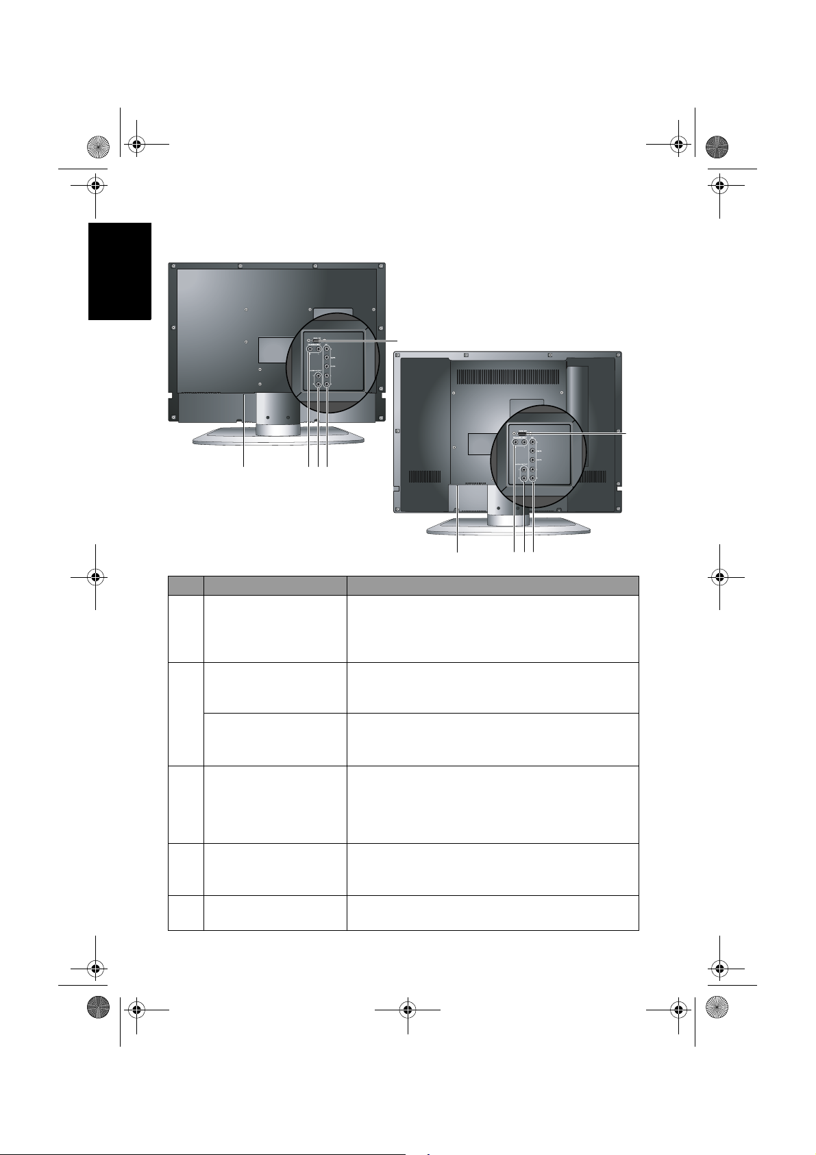
1 Digital tuner slot Reserved for the optional digital tuner.
• VIDEO: Connect to the Composite Video (AV) output as
appropriate for your AV source device. See "Connecting the
Composite Video input" on page 10.
• S-VIDEO: Connect to the S-Video output as appropriate
for your AV source device. See "Connecting the S-Video
input" on page 10.
AV2 (Composite
2
Video (AV) or SVideo)
• AUDIO L/R: Connect to the audio output of either the
Composite Video or S-Video output as appropriate for
your AV source device. See "Connecting the Composite
Video input" on page 10 and "Connecting the S-Video
input" on page 10.
Connect your external AV device using either the
Composite Video or S-Video inputs. If both are connected
to an AV source at the same time, S-Video input takes
preference over Composite Video input. S-Video will
provide a better quality image.
An audio output for connecting an external headset. The
3 Headset socket
display speakers will be muted whenever the headset socket
is being used.
PC D-SUB
4
PC AUDIO IN
Connect to the video (D-Sub) output of a PC. See
"Connecting the PC D-Sub input" on page 11.
Connect to the audio output to match that of the video
output on a PC. See "Connecting the PC D-Sub input" on
page 11.
5 Analog tuner slot Reserved for the optional analog tuner.
1
2
3
4
5
English
Section 1: Quick Start Guide 7
Page 44

V26B_V32B_TW_EN.book Page 8 Monday, October 29, 2007 5:48 PM
Rear view
VB2621
English
5
No. Name Description
1HDMI/DVI
AV 1 Y C
B/PB CR/PR
2
AV 1 L/R
AUDIO OUTPUT
3
L/R
DVI-AUDIO INPUT
4
L/R
5AC-INLET
34
2
1
5
VB3221
4
3
2
Connect to the DVI digital video or HDMI digital
audio/video output of your digital source device. See
"Connecting the DVI input" on page 12 and
"Connecting the HDMI input" on page 12.
Connect each to the Component Video (Y CB/PB CR/
P
R) output of an appropriate video source device. See
"Connecting the Component Video input" on page 11.
Connect each to the audio output of an appropriate
video source device to match that of each Component
Video input. See "Connecting the Component Video
input" on page 11.
Connect to the audio input of an audio or sub-woofer
amplifier. This output is always available, however, its
level is fixed and cannot be controlled by the Volume.
See "Connecting the stereo audio output" on page 13.
Connect to the DVI digital audio output of your
digital source device. See "Connecting the DVI input"
on page 12.
For connecting the AC power cable. See "7. Connect
the power cable" on page 14.
1
Section 1: Quick Start Guide8
Page 45

V26B_V32B_TW_EN.book Page 9 Monday, October 29, 2007 5:48 PM
6. Making connections
Input options
There are multiple sockets on the display for video/graphic and their
corresponding audio inputs (see also "External AV devices terminal panel (left
side view)" on page 7 and "Rear view" on page 8). With these sockets, this
display supports the simultaneous connection of several different types of
signal sources, and permits you to select whichever one of the available
sources you wish to view at any time by pressing
• Video source inputs include:
Component Video.
• Graphic source inputs include: 1 × HDMI/DVI and 1 × PC D-Sub.
Video source inputs
You can connect an external analog video device (like a VCR or TV game
console) to the Composite Video (AV) or S-Video input, and press INPUT on
the display to select
AV2 (for Composite Video input) or AV 2 - S (for S-Video
input) as the input source respectively to view analog video. See "Connecting
the Composite Video input" on page 10 and "Connecting the S-Video input"
on page 10.
If the video source device supports it, you could alternatively connect it using
the Component Video inputs and select
possible analog Video picture. See "Connecting the Component Video input"
on page 11.
Of the analog video signal types mentioned above, Component Video offers the
best quality.
Graphic source inputs
You can connect the D-Sub output of a PC to the display’s PC D-Sub input.
For better picture quality, you can alternatively connect the DVI output (if
available) of the PC to the display’s HDMI/DVI input using a DVI to HDMI
adaptor cable. If your device supports HDMI output, you can also use the
HDMI input on the display for connection. Select the
respectively to view the display. See "Connecting the PC D-Sub input" on page
11, "Connecting the DVI input" on page 12 and "Connecting the HDMI
input" on page 12.
In order to fully utilize the high-definition capability of this display, you should
adjust the output resolution of the source device (for example, DVD player or PC)
to closely match the native resolution of the display. For example, 720p for
Component/HDMI video or 1360 x 768 pixels for PC video. For more information
on how to adjust output resolution, please refer to the documentations of the
device.
Pay attention to the following when making connections:
• Before connecting any devices, please turn all equipment off.
• Familiarize yourself with the connectors and sockets on the equipment you want
to connect and the display. Be aware that if incorrect connections are made,
picture quality may be adversely affected.
• Do not pull cables out of sockets by grasping the cable itself, as you may
damage the cable. Only ever remove cables from sockets by grasping the plug
on the end of the cable.
• Once connected, please ensure that all plugs are fully inserted and firmly
seated.
1 × S-Video, 1 × Composite Video (AV) and 1 ×
AV1 as the input source for the best
INPUT:
PC, DVI or HDMI input
English
Section 1: Quick Start Guide 9
Page 46

V26B_V32B_TW_EN.book Page 10 Monday, October 29, 2007 5:48 PM
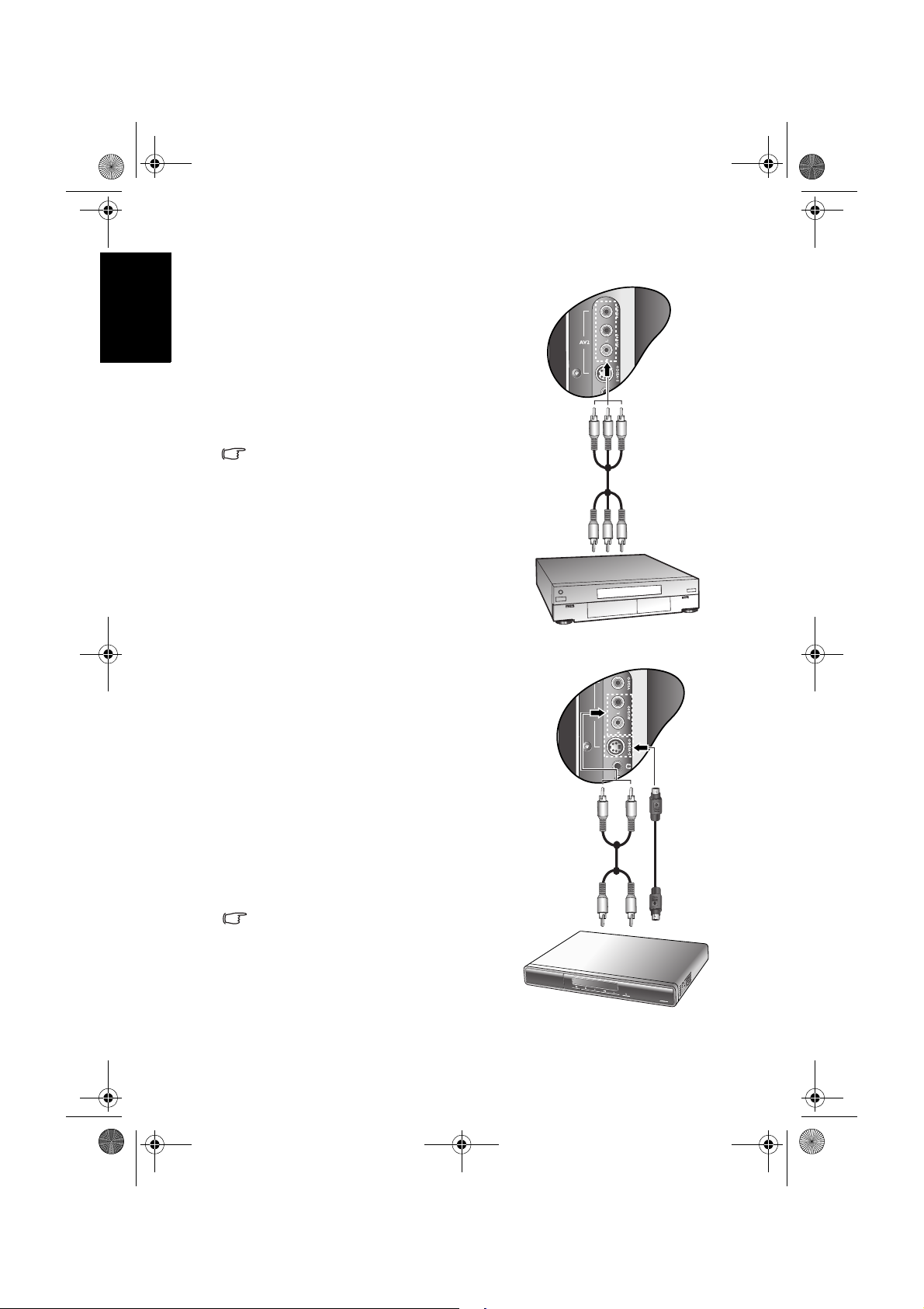
Connecting the Composite Video input
Connect the Composite Video output of your
output equipment (like a VCR) to the AV2
VIDEO and AUDIO L/R terminals on the
display using the Composite Video cable as
illustrated.
A Composite Video cable consists of three
English
connectors: Yellow (video), White (left
channel audio), and Red (right channel
audio). Ensure that the colors of the plugs and
terminals match when making connection.
To view video image from this input, press
INPUT and select AV2.
Composite Video provides the least optimal
image quality. Both S-Video and
Component Video provide better quality
video signals.
AV2 supports both Composite Video and SVideo signal inputs. If you use S-Video, you
cannot use Composite Video for that input.
Composite
Video (AV) cable
VCR
Connecting the S-Video input
1. Connect the S-Video output of your
output equipment (like a DVD player) to
the display's AV2 S-VIDEO terminal using
an S-Video cable (not provided). Pay
attention to the alignment of the plugs on
the S-Video cable when inserting so as not
to damage any pins.
2. Connect the S-Video audio output of the
output equipment to the AV2 AUDIO L
(white)/R (red) input terminals using a
suitable RCA type audio cable.
To view video image from this input, press
INPUT and select AV2-S.
You should not connect both a composite
Video and an S-Video from the same
device; just one or the other. If you have
the choice, use the S-Video instead of
composite Video as an S-video signal
provides a higher quality signal to that of
composite Video.
Section 1: Quick Start Guide10
Audio cable
S-Video
cable
DVD
player
Page 47

V26B_V32B_TW_EN.book Page 11 Monday, October 29, 2007 5:48 PM
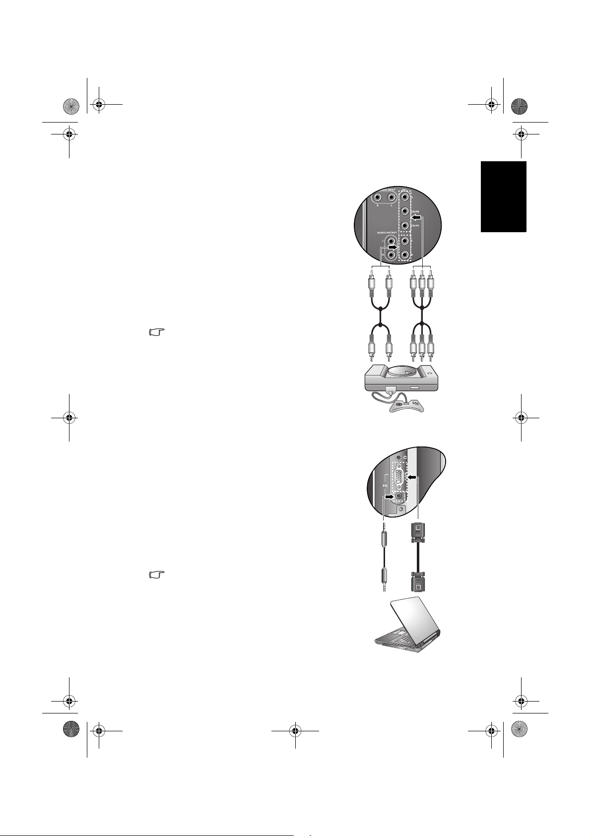
Connecting the Component Video input
1. Connect the Component Video output of
your output equipment (like a TV game
console) to the display's AV1 Y, C
C
R/PR terminals using a Component Video
B/PB and
cable (not provided). A Component Video
cable consists of three plugs: Green (Y),
Blue (C
B/PB), and Red (CR/PR).
2. Connect the Component Video audio
output of your output equipment to the
AV1 L (white)/R (red) input terminals on
the display using a suitable RCA type audio
cable.
To view video image from this input, press
INPUT and select AV1.
Of the analog video signal types,
Component Video offers the best quality.
Ensure that the colors of the plugs and
terminals match when making connection.
For best display results, set the output
resolution of the Component Video source
device to 720p.
See "Supported Component Video input
signal resolutions" on page 30 for
supported resolutions.
Connecting the PC D-Sub input
1. Connect the D-Sub video output of your
PC to the PC D-SUB terminal on the
display using a mini D-Sub (15-pin) cable
(not provided).
2. Connect the audio output of your PC to
the display's PC AUDIO terminal using an
appropriate 3.5mm-diameter Mini-jack
stereo audio cable (not provided).
To view video image from this input, press
INPUT and select PC.
When you connect the display to a PC, you
should adjust the resolution in the display
properties of the computer to closely
match the native resolution of the display
(for example, 1360 x 768 pixels).
See "Supported PC (D-Sub/DVI) input
signal resolutions" on page 30 on other
supported resolutions and "Setting up
appropriate output resolution on PC" on
page 31 on how to set up PC video output.
Audio
cable
Audio
cable
PC
Component
Video cable
TV game
console
Mini D-Sub
cable
English
Section 1: Quick Start Guide 11
Page 48
V26B_V32B_TW_EN.book Page 12 Monday, October 29, 2007 5:48 PM
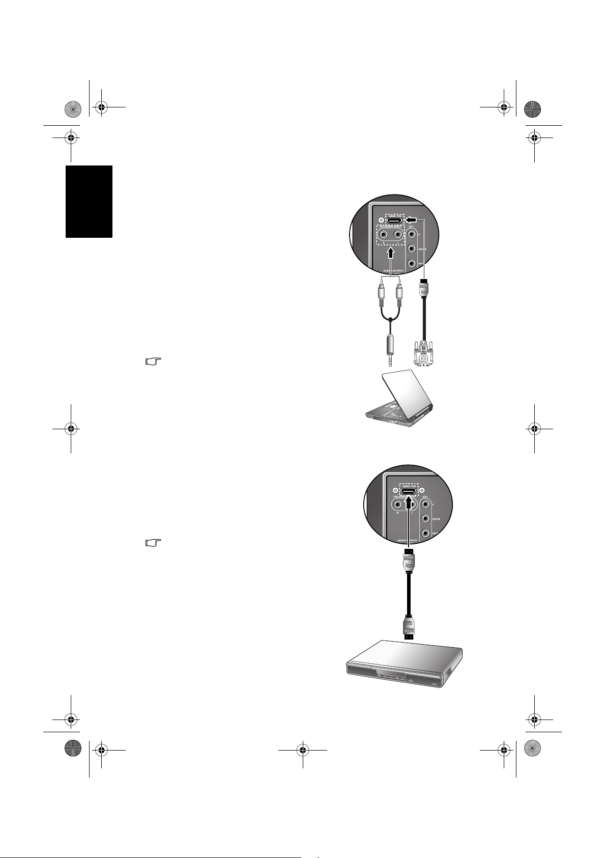
Connecting the DVI input
1. Connect the digital video output of your
output equipment (like a PC or DVD
player) to the HDMI/DVI terminal on the
display using a DVI to HDMI adaptor
cable (not provided).
2. Connect the DVI audio output of your
English
output equipment to the display's DVIAUDIO INPUT L/R input terminals using
a suitable RCA type audio cable.
3. Set the type of DVI input according to the
device connected. See "HDMI/DVI Input"
on page 26.
To view video image from this input, press
INPUT and select DVI.
When connected to a PC, you should
adjust the resolution in the display
properties of the computer to closely
match the native resolution of the display
(for example, 1360 x 768 pixels). See
"Supported PC (D-Sub/DVI) input signal
resolutions" on page 30 on other
supported resolutions and "Setting up
appropriate output resolution on PC" on
page 31 on how to set up PC video output.
Audio
cable
DVI to HDMI
adaptor
cable
PC
Connecting the HDMI input
Connect the HDMI output of your output
equipment to the HDMI/DVI terminal on the
display using an HDMI cable (not provided).
To view video image from this input, press
INPUT and select HDMI.
HDMI (High-Definition Multimedia Interface)
is an uncompressed and all-digital audio/
video interface. HDMI provides an interface
between any audio/video source, such as a
set-top box, DVD player, or A/V receiver
over a single cable.
To ensure the stability and performance of
signal transmission, it is recommended
that you use high-quality and certified cable
for connection
Be aware that HDMI input must be HDCPcompliant to be displayed.
The display’s HDMI input is compliant with
the HDMI 1.2 standard, and supports
display resolution up to 1080i. See
"Supported HDMI input signal resolutions"
on page 31 for all supported HDMI
resolutions.
Section 1: Quick Start Guide12
HDMI cable
DVD
player
Page 49
V26B_V32B_TW_EN.book Page 13 Monday, October 29, 2007 5:48 PM
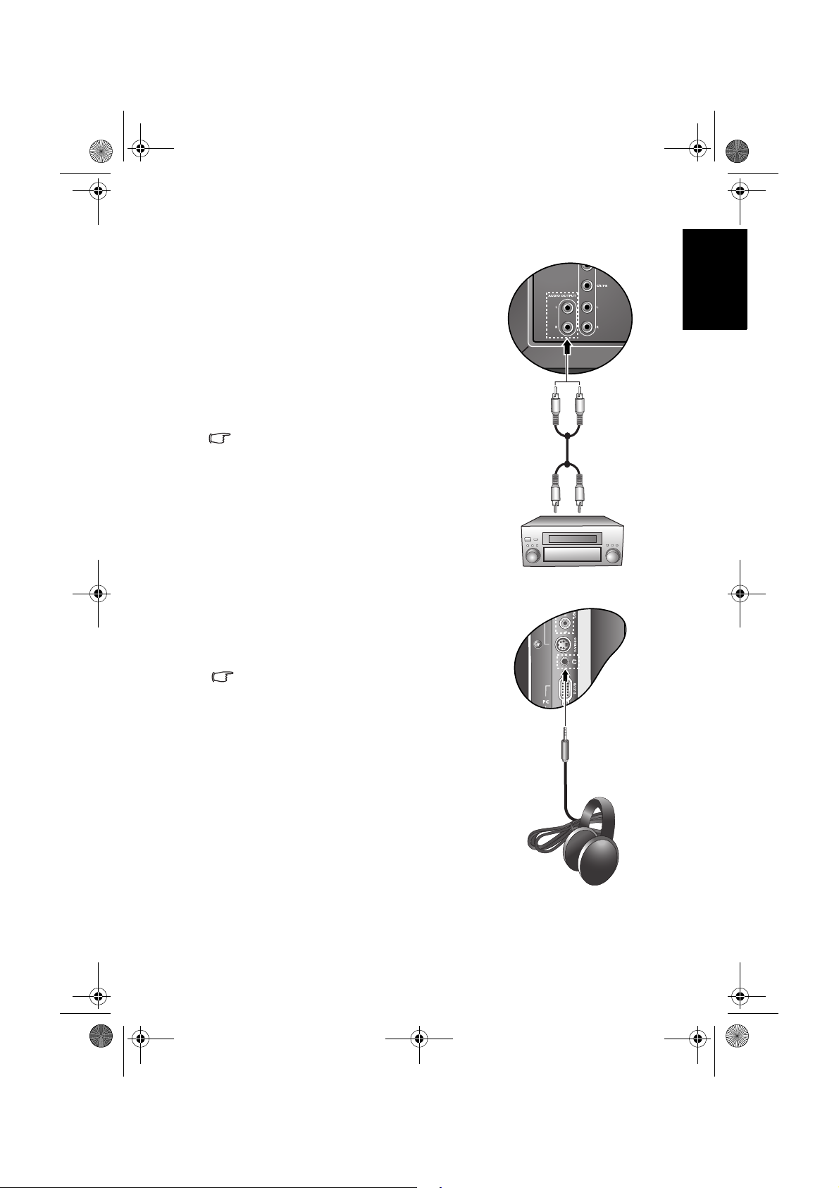
Connecting the stereo audio output
This display provides a set of stereo audio
output terminals (RCA type) for delivering the
audio signal to a sound system or other audio
devices.
1. Connect the audio input terminals of an
amplifier or other audio device to the
AUDIO OUTPUT L/R terminals on the
display using a suitable RCA type audio
cable.
2. Set the
Speaker Out option in the Audio
menu to
Off.
This output is always available. Its level is
fixed and cannot be adjusted by the Volume
setting of the display.
Audio cable
Audio
amplifier
English
Connecting the headset audio output
This display provides a stereo headset output
socket for delivering the audio signal to a
stereo headset.
Connect the stereo headset plug (3.5mm
Mini-jack type) to the stereo headset output
socket on the display using a suitable audio
cable.
Once connected, the display speakers will
be muted automatically. The volume level
can be adjusted by pressing the VOL
(Volume)
Avoid prolonged use of the headset or
listening in an excessive volume level,
otherwise your hearing will be damaged.
+ and - buttons on the display.
Headset
Section 1: Quick Start Guide 13
Page 50
V26B_V32B_TW_EN.book Page 14 Monday, October 29, 2007 5:48 PM
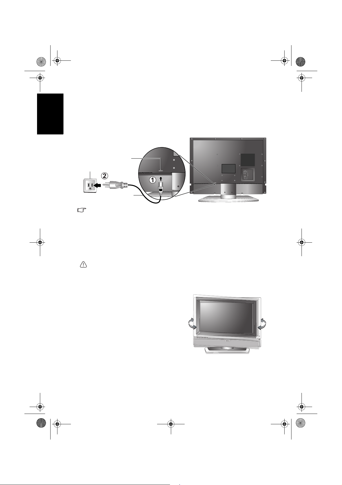
7. Connect the power cable
1. Locate the power cable from the packaging, and plug the appropriate end
English
into the
2. Plug the other end into an appropriate wall power outlet, and turn on the
switch (if the power outlet is switched). The display will enter standby
mode and the power indicator (on the front lower right) will light up red.
Power
outlet
• The type of power cable plug and socket illustrated may differ from the type
used in your region.
• Only use an appropriate power cable for your region. Never use a power cable
which appears damaged or frayed.
• Never change the plug type on a power cable. Be aware of total loading when
using extension cords or multiple outlet power boards.
• This display has no power switch. When installing the display, incorporate a
readily accessible disconnect device in the fixed wiring, or connect the power
cord to socket-outlet which must be provided near the display and easily
accessible. If a fault should occur during operation of the unit, operate the
disconnect device to switch the power supply off, or disconnect the power cord.
WARNING: This display has been engineered and manufactured with the highest
priority on safety, however, IMPROPER HANDLING OR USE CAN RESULT IN
POTENTIAL ELECTRICAL SHOCK OR FIRE HAZARD. Please handle this display
with care. If damaged, turn off the power and unplug the power cable from the
display. Transport the display to your nearest BenQ authorised service centre for
repair.
AC-INLET socket on the rear of the display (as illustrated below).
AC-INLET
socket
Power cable
8. Adjust the viewing angle
This display is equipped with a adjustable
swivel base. If necessary, turn the display
screen to an appropriate angle (maximum 30
degrees left and right) for more comfortable
viewing.
Section 1: Quick Start Guide14
Page 51

V26B_V32B_TW_EN.book Page 15 Monday, October 29, 2007 5:48 PM
9. Basic operations
Power on, off and standby
Make sure that the display is connected to the power outlet and switched on (if
the power outlet is switched).
Turning the display on
After plugging the display's power cable into a wall outlet, the display will
enter standby mode automatically. The power indicator will light up red.
(Power/standby) on the display. The display will turn on and the
Press
power indicator will change to green.
Putting the display to standby
Press (Power/standby) on the display again, and the display will return
to standby mode. The power indicator will turn red.
The display still consumes a very small amount of power (about 1.5W) in standby
mode.
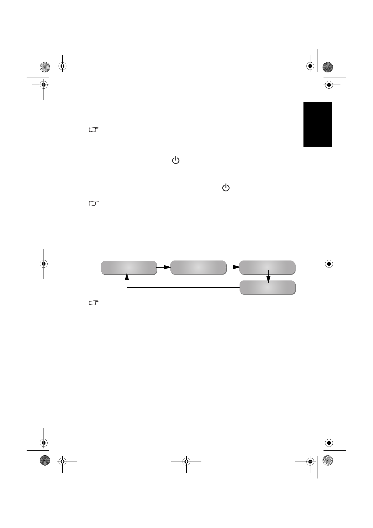
Switching inputs
1. Turn on the display.
2. Turn on the connected video source equipment or device.
3. Press
INPUT on the display to view the current selected input. Press the
button repeatedly until your desired input is displayed. The sequence is as
follows:
English
AV1 AV2 (or AV2-S) HDMI (or DVI)
PC
• These options will only appear when corresponding signals are connected to
the display.
• If both Composite Video (AV) and S-Video signals are connected to the AV2
input at the same time, only S-Video input will be displayed. If you wish to view
the Composite Video (AV) input in such case, remove the S-Video connection
temporarily.
• Be aware that HDMI input must be HDCP-compliant to be displayed. When
switching to the HDMI input, the display needs approximately 3 seconds to
detect the HDCP information from the signal source and no image will be
displayed during this period. This is not a malfunction.
• When displaying PC video, remember to switch the PC video output setting from
monitor display to external device. For more information, refer to the
documentations of your PC.
Adjusting volume
• Press VOL (Volume) + on the display to increase volume. The volume
indicator increases in length as volume rises.
• Press
VOL (Volume) - on the display to decrease volume. The volume
indicator decreases in length as volume falls.
Section 1: Quick Start Guide 15
Page 52
V26B_V32B_TW_EN.book Page 16 Monday, October 29, 2007 5:48 PM
Care and cleaning information
• Always turn off the display and disconnect it from the mains power before
cleaning.
• Do NOT use cream, liquid, aerosol or spray cleaners. Use only a slightly
damp well wrung-out (drip-free) and lint-free, clean soft cloth and lightly
wipe the display.
English
• If necessary, use a pH-neutral liquid dish-washing detergent diluted with
water on a separate clean lint-free cloth to remove oil or grease marks. Wipe
over again with a clean dry lint-free cloth to remove any smear marks.
• Under close examination and in certain circumstances, you may notice that a
few non-active pixels appear on the screen as a fixed point of color. Please
note that this does not affect the performance of your product as it is usually
not visible at normal viewing distances.
• If the display is not going to be used for an extended period of time (like
when you are going away for holidays), it should be switched off and
unplugged from the wall outlet. You should also consider removing the
batteries from the remote control (as they may leak).
• LCD (Liquid Crystal Display) screens, like plasma (PDP) and conventional
CRT (Cathode Ray Tube) screens, are also susceptible to 'screen burn-in' or
'image retention' which can be found on the screen as visible fixed lines and
shades and can't be removed. To avoid such permanent damage to the screen,
it is advisable to take the following preventive actions:
(1) Avoid displaying still (inactive) image s for more than two hours.
(2) Change the screen image aspect ratio from time to time.
(3) If it is necessary to display still images for a long time, lower the contrast
and brightness.
(4) Turn on the ECO function when displaying PC input image (See "ECO"
on page 26).
What's next?
You have reached the end of Section 1: Quick Start Guide. By now, you should
have a reasonable understanding of your new LCD display and its controls,
know how to install, connect, turn on and how to care for and maintain it.
Should you wish to maximize your viewing experience pleasure, Section 2 of
this booklet contains the User Manual which describes how to customise the
display settings to suit your preferences and viewing environment. It details
the features and functions of the display and provides product specifications
and troubleshooting information for your further assistance.
Section 1: Quick Start Guide16
Page 53

V26B_V32B_TW_EN.book Page 17 Monday, October 29, 2007 5:48 PM
English
VB2621/VB3221 LCD Display
Section 2: User Manual
Welcome
Page 54

V26B_V32B_TW_EN.book Page 18 Monday, October 29, 2007 5:48 PM
OSD (On-Screen Display) menu
OSD structure
Input signal type
AV2 (AV 2- S) P C
• Picture Mode
• Contrast
• Brightness
• Color
• Sharpness
• Color TEMP.
• Backlight
• NTSC Tint
• NTSC Setup
• Contrast
• Brightness
• Color
TEMP.
• Backlight
• Auto
Adjust
• Frequency
• Phase
• H. Position
• V. Position
(Not available)
English
Audio
Picture
Senseye
Setup
• The available menu items are dependent on the input source being selected.
• Settings under different input sources can be adjusted independently. For
AV 1
• Volume
• Balance
• Sound Type
• Steady Sound
• Surround
• Speaker Out
• Advanced Audio Settings
• Picture
Mode
• Contrast
• Brightness
• Color
• Sharpness
• Color
TEMP.
• Backlight
• Black Extension
• ACE
• Noise Reduction
• Language
• Sleep Timer
• ECO
• HDMI/DVI Input
• Blue Screen
• Reset All Settings
Unavailable items will be greyed out or not displayed.
example, the Picture settings for the AV1 input will not affect the Picture
settings for the AV2 (or AV2-S) input.
DVI
(PC
mode)
• Contrast
• Brightness
• Color TEMP.
• Backlight
DVI
(Video
mode)
HDMI
OSD (On-Screen Display) menu18
Page 55
V26B_V32B_TW_EN.book Page 19 Monday, October 29, 2007 5:48 PM
Navigating the OSD menu
You can use the On-Screen Display (OSD) menu to adjust the settings on
your display. To display the OSD menu, press
MENU on the display.
Audio
Picture
Operations in the OSD menu
• Press CH (Selection) , CH (Selection) , VOL (Volume)
+
or VOL (Volume) - to make selections or change settings.
• Press
INPUT to confirm your selection or enter an submenu
(if available).
MENU to return to the previous menu level, or close
• Press
the OSD menu.
For example, to adjust picture sharpness:
1. Press
2. Press
3. Press
4. Press
5. Press
6. Press
For details see:
• "Audio menu" on page 20
• "Picture menu" on page 22
• "Senseye menu" on page 25
• "Setup menu" on page 26
MENU to display the OSD menu on-screen.
VOL (Volume) + or VOL (Volume) - to select
Picture.
INPUT to enter the submenu.
CH (Selection) or CH (Selection)to select
Sharpness.
VOL (Volume) + or VOL (Volume) - to make
adjustment.
MENU several times to close the OSD menu.
Senseye
TV Setup
English
OSD (On-Screen Display) menu 19
Page 56
10
0
V26B_V32B_TW_EN.book Page 20 Monday, October 29, 2007 5:48 PM
Audio
Audio menu
English
The available menu items are
dependent on the input source
being selected.
The illustration is for reference
only.
Volume
Balance
Sound Type Stereo
Steady Sound Off
Surround Off
Speaker Out On
Advanced Audio Settings >
Item Function Operation Range
Volume
Balance
Adjusts the volume level of
the display’s built-in
speakers.
Adjusts left or right speaker
volume level.
Press
VOL + to increase or
VOL- to decrease volume.
VOL+to increase right
Press
speaker volume,
VOL- to
increase left speaker
volume level.
Selects a sound type when
viewing programs or videos
that support multiple
Sound Type
Steady
Sound
sounds.
Available options are
dependent upon the
received signal.
If set to
Auto, the display
automatically adjusts the
sound level to be constant
Press VOL+ or VOL- to
change selection.
amongst different channels.
Activates or deactivates the
Surround
SRS TruSurround XT
sound effect.
Enables (On) or disables
Speaker
Out
(Off) sound output to the
built-in speakers of the
display.
Advanced Audio Settings - Press
This menu item becomes unavailable if the Surround item is set to SRS TruSurround
XT.
INPUT to enter.
回上頁
0 to 47
-12 to 12
• Stereo
• Mono
• SAP
• Sound 1
• Sound 2
• Language 1
• Language 2
• Auto
• Off
• SRS
TruSurround
XT
• Off
• On
• Off
OSD (On-Screen Display) menu20
Page 57

V26B_V32B_TW_EN.book Page 21 Monday, October 29, 2007 5:48 PM
EQ Mode
Treble
Mid Treble
Middle
Mid Bass
Bass
To restore a factory preset
or user customised EQ
Mode.
Adjusts treble tones for the
Personal EQ Mode.
Adjusts mid-treble tones for
the
Personal EQ Mode.
Adjusts mid tones for the
Personal EQ Mode.
Adjusts mid-bass tones for
Personal EQ Mode.
the
Adjusts bass tones for the
Personal EQ Mode.
VOL+ or VOL- to
Press
change selection.
VOL+ or VOL- to
Press
make adjustment.
Setting up Personal EQ Mode
You can adjust the settings in the Advanced Audio Settings menu and save
them as your
1. Press
2. Press
Audio menu.
3. Press
INPUT to enter the Advanced Audio Settings menu.
4. Press
select
5. Press
Bass, and then press VOL+ or VOL- to adjust the settings to your
satisfaction.
6. Press
Personal EQ Mode.
MENU to display the OSD menu on-screen.
VOL+ or VOL- to select Audio, and then press INPUT to enter the
CH or CHto select Advanced Audio Settings, and then press
CHor CHto select EQ Mode, and then press VOL+ or VOL- to
Personal.
CHor CHto select Treble, Mid Treble, Middle, Mid Bass or
MENU to save the settings and close the OSD menu.
• Rock
• JAZZ
• Classic
• POP
• Personal
English
-12 to 12
OSD (On-Screen Display) menu 21
Page 58

32
32
3245
32
V26B_V32B_TW_EN.book Page 22 Monday, October 29, 2007 5:48 PM
Picture
Picture Mode
Picture menu
English
The available menu items are
dependent on the input source
being selected.
The illustration is for reference
only.
Contrast
Brightness
Color
Sharpness
Color TEMP. Normal
Backlight
NTSC Tint
NTSC Setup 7.5 IRE
Item Function Operation Range
Provides complete preferred
setups adjusted for color,
contrast, brightness and
sharpness to suit various
viewing situations. If
Personal
is selected, you can customize
Picture
Mode
individual picture setting to
your satisfaction.
For more information about
Press
VOL+ or
VOL- to change
selection.
when to use these modes and
how to setup the
Personal
picture mode, see "Using the
Picture Modes" on page 24
and "Setting up the Personal
Picture Mode" on page 24.
Adjusts image white level so
that whites do not wash out
Contrast
surrounding colors. See
"Adjusting the contrast" on
page 24.
Adjusts image black level, so
that detail in the dark areas of
Brightness
an image can be seen. See
"Adjusting the brightness" on
page 24.
Color Adjusts image color intensity.
Press
VOL+ for
brighter whites,
VOL- for darker
whites.
VOL+ for
Press
brighter blacks,
VOL- for darker
blacks.
VOL+ for
Press
more intense
colors,
VOL- for
less intense colors.
Standard
回上頁
• Standard
• Cinema
• Dynamic
• Game
• Personal
0 to 64
OSD (On-Screen Display) menu22
Page 59

V26B_V32B_TW_EN.book Page 23 Monday, October 29, 2007 5:48 PM
VOL+ for
Press
Sharpness Adjusts image sharpness level.
sharper image,
VOL- for softer
image.
Color
TEMP.
Adjusts the color tint of the
black and white part of the
image.
VOL+ or
Press
VOL- to make
adjustment.
Backlight Adjusts backlight intensity. 0 to 10
Adjusts color tint in NTSC
NTSC Tint
video.
This option is only
available for NTSC video
sources.
Press VOL+ for
redder tones, VOL-
for greener tones.
Sets up the NTSC video
display format to match that
NTSC
Setup
of the input NTSC video input
from other devices (such as a
DVD player).
This option is only
available for NTSC video
sources.
Press VOL+ or
VOL- to change
selection.
Automatically adjusts
Auto
Adjust
Frequency, Phase, H. Position
and V. Position to place the PC
input image on the screen.
Press
INPUT to begin the auto
adjustment function.
Frequency Adjusts the display clock
frequency and phase to correct
Phase
H. Position
V. Position
shimmering or distortion of
the displayed image.
Adjusts the horizontal and
vertical positions of the
displayed image in order to
center it on the screen.
Press
VOL+ or
VOL- to make
adjustment.
0 to 6
• Warm
• Normal
• Cool
English
0 to 64
• 0 IRE
• 7.5 IRE
(Dependent upon
the resolution of
the input signal)
OSD (On-Screen Display) menu 23
Page 60

V26B_V32B_TW_EN.book Page 24 Monday, October 29, 2007 5:48 PM
Using the Picture Modes
You can choose a Picture Mode to suit your viewing condition:
Picture Mode Description
Suitable for viewing in environments with normal lighting
condition.
In this mode, the contrast and levels of colors are optimized in
order to display more details in the bright and dark areas of images.
The contrast, brightness and color saturation are enhanced for
displaying vivid images in public areas.
Images are displayed with moderate brightness and contrast,
making it suitable for prolonged viewing.
Your own customised picture mode. See "Setting up the Personal
Picture Mode" on page 24.
English
Standard
Cinema
Dynamic
Game
Personal
Adjusting the contrast
1. Set the contrast to the highest level.
2. Gradually decrease the contrast level until you reach the point where the
details in the bright areas of the image can be seen clearly. Do not further
decrease the contrast level to avoid losing the saturation of colors.
Adjusting the brightness
1. Set the brightness to the lowest level.
2. Gradually increase the brightness level until you reach the point where the
details in the dark areas of the image can be seen clearly. Do not further
increase the brightness level to avoid the black areas from looking grayish.
Setting up the Personal Picture Mode
You can adjust the settings in the Picture menu and save them as your
Personal Picture Mode.
1. Press
2. Press
3. Press
4. Press
5. Press
MENU to display the OSD menu on-screen.
VOL+ or VOL- to select Picture, and then press INPUT to enter the
Picture menu.
CH or CHto select Picture Mode, and then press VOL+ or VOL-
to select
etc., and then press
Personal.
CHor CHto select Contrast, Brightness, Color, Sharpness...,
VOL+ or VOL- to adjust the settings to your
satisfaction.
MENU to save the settings and close the OSD menu.
OSD (On-Screen Display) menu24
Page 61

V26B_V32B_TW_EN.book Page 25 Monday, October 29, 2007 5:48 PM
Senseye menu
The available menu items are
dependent on the input source
being selected.
The illustration is for reference
only.
Item Function Operation Range
Enhances the contrast among
details when viewing dark
Black
Extension
ACE (Auto
Contrast
Enhancement)
images.
This option will not be
available if the ACE
function is set to Low,
Middle or High.
Adjusts the auto contrast
enhancement function that
optimizes the image contrast
ratio for interlaced inputs.
Adjusts the image noise
reduction function that helps
to remove noise in images.
Noise
Reduction
This function is only
available when AV1 or
AV2 (AV2-S) is the input
source with the
resolution no higher than
480i and 576i.
Black Extension Low
ACE
Noise Reduction Low
Press VOL+ or
VOL- to change
selection.
Off
• Low
• Middle
• High
• Off
• Low
• Middle
• High
• Off
• Low
• Middle
• High
• Off
回上頁
English
OSD (On-Screen Display) menu 25
Page 62

V26B_V32B_TW_EN.book Page 26 Monday, October 29, 2007 5:48 PM
Setup
Setup menu
English
The available menu items are
dependent on the input source
being selected.
The illustration is for reference
only.
Language English
Sleep Timer Off
ECO Off
HDMI/DVI Input PC
Blue Screen
Reset All Settings
Item Function Operation Range
Language
Select your desired language for the OSD
menu.
Set the Sleep Timer to automatically turn
off the display. 1 minute before
shutdown, a message will display on-
Sleep
Timer
screen. At this time, if you wish to cancel
the function, press any button on the
remote control.
Once the time expires, the display will be
put to the standby mode automatically.
Once set to
On, the display will activate
the Display Power Management System
VOL+ or
Press
VOL- to change
selection.
(DPMS) and enter power saving mode
ECO
when no PC input signal is detected for 5
seconds, or enter standby mode
automatically if no Video signal is
detected for 10 minutes.
Select the DVI input mode according to
HDMI/DVI
Input
Blue
Screen
Reset All
Settings
the device connected. Select
connected. If a video device (for example,
a digital Set Top Box) is connected, select
Video.
Once set to
On, if no input signal is
detected, a blue screen will be displayed
automatically.
Restore all settings to their default values.
PC if a PC is
Press
INPUT to activate the
reset.
Off
回上頁
• English
• 繁中
Off, 15, 30,
45, 60, 90,
120
(minutes)
• Off
• On
• PC
• Video
• Off
• On
OSD (On-Screen Display) menu26
Page 63

V26B_V32B_TW_EN.book Page 27 Monday, October 29, 2007 5:48 PM
Reference
Disclaimer
BenQ Corporation makes no representations or warranties, either expressed
or implied, with respect to the contents of this document. BenQ Corporation
reserves the right to revise this publication and to make changes from time to
time in the contents thereof without obligation to notify any person of such
revision or changes.
Copyright
Copyright 2007 BenQ Corporation. All rights reserved. No part of this
publication may be reproduced, transmitted, transcribed, stored in a retrieval
system or translated into any language or computer language, in any form or
by any means, electronic, mechanical, magnetic, optical, chemical, manual or
otherwise, without the prior written permission of BenQ Corporation.
is a trademark of SRS Labs, Inc. TruSurround XT technology is
incorporated under license from SRS Labs, Inc.
Dimensions
VB2621
English
Unit: mm
Reference 27
Page 64
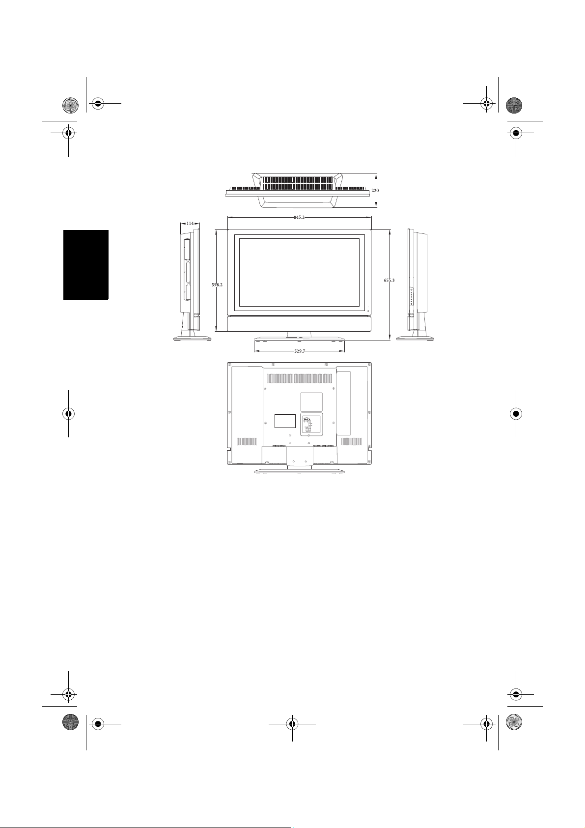
V26B_V32B_TW_EN.book Page 28 Monday, October 29, 2007 5:48 PM
VB3221
English
Unit: mm
Reference28
Page 65
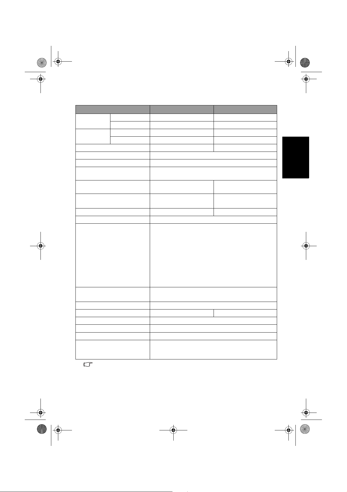
V26B_V32B_TW_EN.book Page 29 Monday, October 29, 2007 5:48 PM
Specifications
Model
We i gh t
Dimensions
(W × H × D)
With swivel 11.68 Kg 15.04 Kg
Without swivel 10.98 Kg 14.34 Kg
With swivel 725.6 × 579.7 × 220 mm 845.2 × 655.3× 220 mm
Without swivel 725.6 × 553.1 × 105.7 mm 845.2 × 598.2 × 114 mm
LCD panel size (approx. value) 26 inches 32 inches
Aspect ratio 16:9
Native resolution 1366 × 768
LCD panel brightness
(typical)
LCD panel contrast ratio
(typical)
Viewing angle
(Left/Right/Up/Down)
Response time (Gray to Gray) 8 ms 6.5 ms
Built-in speakers 8W × 2, 80Hz ~ 20KHz
Signal input
Signal output
Power supply AC 100 - 240V, 50/60 Hz
Power consumption 120W 160W
Operating temperature
Storage temperature
Video system Supports NTSC/PAL/SECAM formats
Remote control model
number (marked in the
battery compartment)
Design and specifications are subject to change without notice.
VB2621 VB3221
500 cd/m
2
800:1 1500:1
°°°° °°°°
80 /80 /80 /80 89 /89 /89 /89
• Composite Video (AV) × 1
• S-Video × 1
• Composite Video/S-Video audio × 1
• Component Video (Y C
B/PB CR/PR) × 1
• Component Video audio × 1
• HDMI/DVI × 1
• DVI audio × 1
• PC D-Sub × 1
• PC audio × 1
• Stereo audio × 1
• Headset × 1
0 ~40 (at sea level)
°C °C
-20 ~ 50 (at sea level)
°C °C
RC-H072
English
Reference 29
Page 66
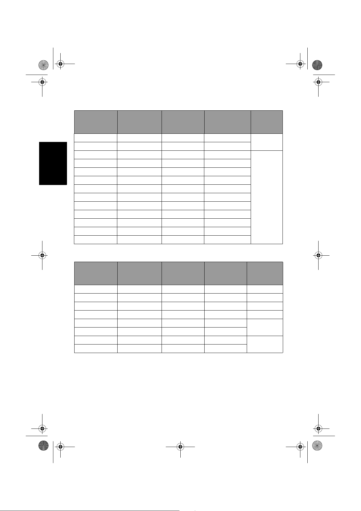
V26B_V32B_TW_EN.book Page 30 Monday, October 29, 2007 5:48 PM
Supported PC (D-Sub/DVI) input signal resolutions
Horizontal
Resolution
720 × 400 31.47 70.08 28.322
640 × 480 31.5 60 25.18
English
640 × 480 37.5 75 31.5
640 × 480 37.86 72.81 31.5
800 × 600 37.9 60.32 40
800 × 600 46.9 75 49.5
800 × 600 48.08 72.19 50
1024 × 768 48.4 60 65
1024 × 768 56.5 70 75
1024 × 768 60.023 75 78.75
1280 × 768 47.8 60 79.5
1280 × 768 60.3 75 102.25
1360 × 768 47.7 60 85.5
Frequency
(KHz)
Vertical
Frequency
(Hz)
Dot Clock
Frequency
(MHz)
Supported Component Video input signal resolutions
Horizontal
Resolution
720 × 480i 15.735 60i 13.5 SDTV 480i
720 × 480p 31.25 60p 27 EDTV 480p
720 × 576i 15.625 50i 13.5 EDTV 576i
720 × 576p 31.25 50p 27 EDTV 576p
1280 × 720p 45 60p 74.25
1280 × 720p 37.5 50p 74.25
1920 × 1080i 33.75 60i 74.25
1920 × 1080i 28.13 50i 74.25
Frequency
(KHz)
Vertical
Frequency
(Hz)
Dot Clock
Frequency
(MHz)
Note
DOS
VESA
Note
HDTV720p
HDTV1080i
Reference30
Page 67
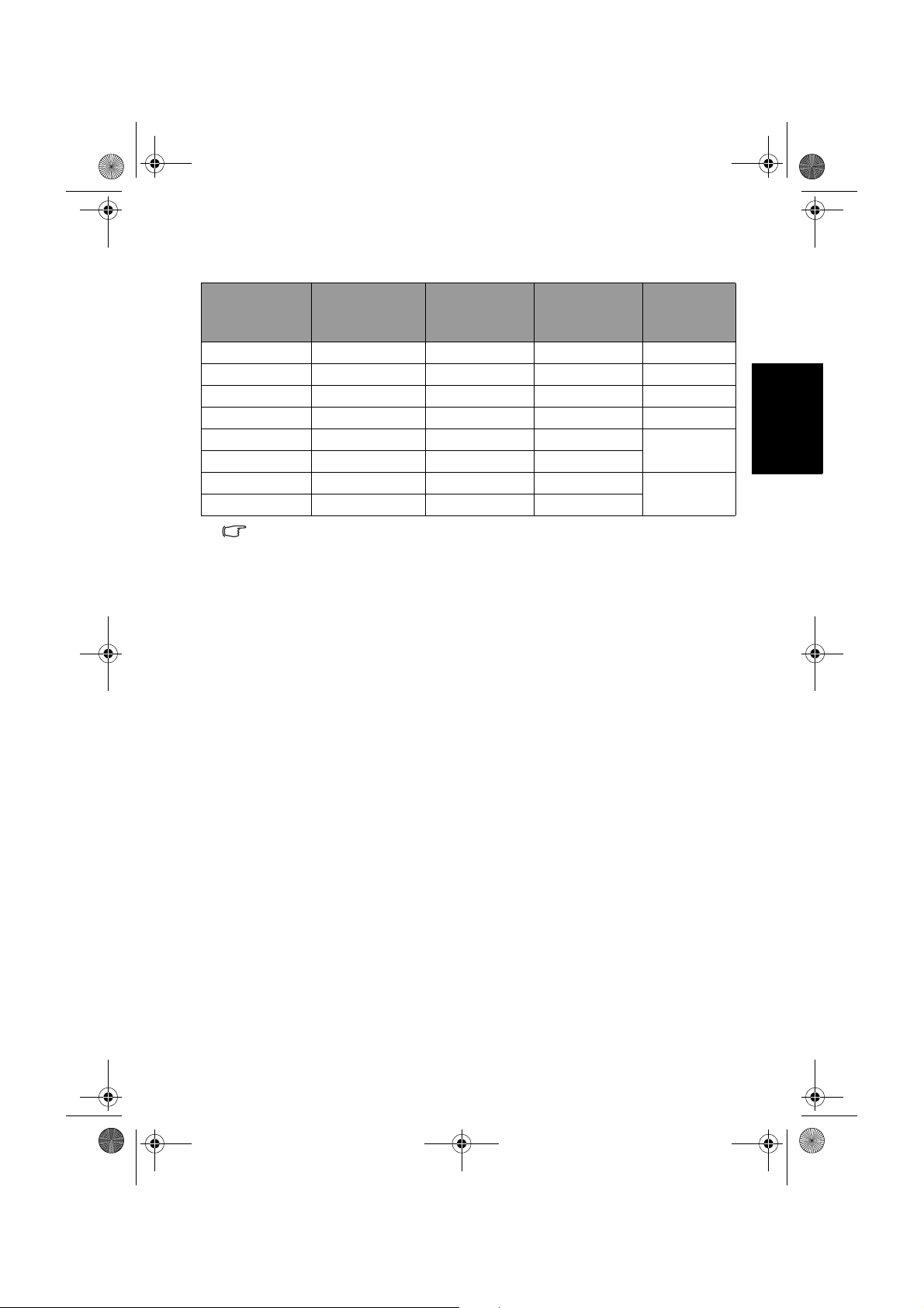
V26B_V32B_TW_EN.book Page 31 Monday, October 29, 2007 5:48 PM
Supported HDMI input signal resolutions
Resolution
Horizontal
Frequency
(KHz)
Vertical
Frequency
(Hz)
Dot Clock
Frequency
(MHz)
Note
720 × 480i 15.735 60i 27 SDTV 480i
720 × 480p 31.47 60p 74.25 EDTV 480p
720 × 576i 15.625 50i 27 EDTV 576i
720 × 576p 31.25 50p 74.25 EDTV 576p
1280 × 720p 45 60p 74.25
1280 × 720p 37.5 50p 74.25
1920 × 1080i 28.13 50i 74.25
1920 × 1080i 33.75 60i 74.25
• Resolutions outside of these tables are not recognized and will not be
displayed.
• When you connect the display to a PC, you should adjust the resolution in the
display properties of the computer to closely match the native resolution of the
display (for example, 1360 x 768 pixels).
• To view the best quality picture when using the PC input, you will then need to
instruct the display to calibrate itself to the PC signal timing. To do so, select
'Auto' in the 'Picture' menu. See "Auto Adjust" on page 23.
HDTV720p
HDTV1080i
Setting up appropriate output resolution on PC
Before connecting the display to a PC to display PC video, please follow the
instructions below (in Windows XP for example) to setup appropriate output
resolution.
1. On Windows Desktop, right-click and select
that appears.
2. Click the
3. Drag the
Settings tab in the window that follows.
Resolution slider and select a compatible resolution according to
"Supported PC (D-Sub/DVI) input signal resolutions" on page 30. If your
PC supports it, select 1360 × 768 as the output resolution for the best
result.
4. Click
OK to save the setting and close the window.
5. Switch the PC video output from monitor to the display.
6. Press
INPUT on the display and select the PC input.
Properties from the menu
English
Reference 31
Page 68

V26B_V32B_TW_EN.fm Page 32 Wednesday, October 31, 2007 11:20 AM
Troubleshooting
There are many external influences and circumstances beyond the control of
BenQ which may be causing problems with your display. Some of the more
common and user fixable problems are listed below for your information.
Please check the following list before calling your nearest BenQ Customer
Service Center, and attempt the following steps to diagnose and fix the
problem yourself:
English
Symptoms Possible causes
• Check that the power switch on the power outlet is
turned on.
The display does not
turn ON
There is no picture or
sound
The cable connection
is correct, but there is
only sound and no
picture is displayed
• Check that the power plug is securely inserted into both
the
AC-INLET socket on the display and the wall outlet,
and that the wall outlet is switched on (if switched).
• Check that power is available from the power outlet by
trying another known working appliance (e.g. desk
lamp) from that same power outlet.
• Check that the display is turned on (The power indicator
should be green).
• Try a different input source to confirm if the symptom is
still present or whether the source is at fault.
• Check for mis-connection of cables for that input.
• Adjust the volume control to check that isn't turned
down.
• Make sure that the
menu is not set to
• If the display is connected to a PC, make sure that the PC
is not in standby or hibernation mode, and the PC’s
video display is switch to external output.
• Check to make sure that the cables are firmly connected
to the terminals on the display.
• According to the type of input signal connected, refer to
"Supported PC (D-Sub/DVI) input signal resolutions" on
page 30, "Supported Component Video input signal
resolutions" on page 30 or "Supported HDMI input
signal resolutions" on page 31 to ensure that the input
signal resolution from the signal source device (e.g., the
PC or TV game console) is supported by the display
(maximum 1080i for HDMI and Component Video
inputs, and 1360 × 768 @ 60Hz for PC and DVI inputs).
If the input signal resolution is too high or not
supported, the picture will not be displayed. Lower or
select a compatible signal resolution on the signal source
device and try again.
Speaker Out option in the Audio
Off.
Reference32
Page 69

V26B_V32B_TW_EN.fm Page 33 Wednesday, October 31, 2007 11:20 AM
• Ensure the display's aspect ratio is correctly set to suit the
The image appears
distorted
image source.
• Try a different input source to confirm if the symptom is
still present or whether the source is at fault.
• Lower the
Contrast setting.
• The output resolution of the source device (e.g. DVD
The image appears
too 'washed out', or
the darkest areas of
the image appear too
bright
player) may be set too high. Reduce its output resolution.
• The video signal has not been terminated properly
somewhere in the external equipment. Check the
connection and try again.
• Reduce the brightness level until the black areas of the
picture appear as black.
• The input source device (e.g. DVD player) brightness
level may be set too high. Reduce its brightness level.
• Check the connection of cables.
• The PC video output resolution is not supported by the
display and cannot be displayed. Refer to "Supported PC
(D-Sub/DVI) input signal resolutions" on page 30 and
Picture is not clear, or
there is no image
display when viewing
PC input
"Setting up appropriate output resolution on PC" on
page 31 to select a compatible output resolution on the
PC and try again.
• The PC output resolution is set too high. 1360 × 768 @
60Hz is the highest acceptable PC timing.
• If the displayed image appears to be shimmering and
unclear, use the Auto Adjust function in the
menu to let the display adjust the picture settings
automatically.
• Check for incorrect battery orientation.
• Check for dead batteries
• Check your distance and angle from the display.
• Check whether remote control is properly being pointed
at the display's remote control sensor window.
Remote control does
not function properly
• Check for any obstacle between the remote control and
the remote control sensor window.
• Check that the remote control sensor window is not
under strong fluorescent lighting. or in direct sunlight.
• Check for any devices (PC or personal digital assistant,
PDA) nearby that transmit infrared signals which may
cause interference to signal transmission between the
remote control and the display. Turn off the infrared
function of these devices.
English
Picture
Reference 33
Page 70

V26B_V32B_TW_EN.book Page 34 Monday, October 29, 2007 5:48 PM
<Memo>
English
Reference34
 Loading...