

Page 1
FCC_E.fm Page 1 Friday, August 9, 2002 5:33 PM
FCC Warning
This equipment has been tested and found to comply with the limits for
Class A & Class B digital device, pursuant to Part 15 of the FCC rules.
These limits are designed to provide reasonable protection against harmful
interference when the equipment is operated in a residential environment.
This equipment generates, uses, and can radiate radio frequency energy
and, if not installed and used in accordance with this user's guide, may
cause harmful interference to radio communications. However, there is no
guarantee that interference will not occur in a particular installation.
CE Mark Warning
This device complies with requirements of EN50081-1 and EN50082-1
under the scope of EMC Directive EEC.
Trademarks
Copyright ©2002 BenQ Corporation.
Contents subject to change without prior notice. BenQ is a registered
trademark of BenQ Corporation. All other trademarks belong to their
respective proprietors.
Copyright Statement
No part of this publication may be reproduced in any form or by any
means or used to make any derivative such as translation, transformation,
or adaptation without permission from BenQ Corporation.
Page 2
8PUG.book Page i Friday, August 9, 2002 5:32 PM
Ta b l e o f C o n t e n t s
1. Introduction ......................................................................... 1
1.1. Product Overview ......................................................................... 1
1.2. Features & Specifications .............................................................. 2
1.2.1. Features .............................................................................................. 2
1.2.2. Technical Specifications ................................................................... 2
1.2.3. Physical Specifications ...................................................................... 3
1.3. Terminology .................................................................................... 3
1.4. Package contents ............................................................................ 3
2. Installation ............................................................................. 4
2.1. Operating Environment ................................................................ 4
2.2. Connecting to network devices ................................................. 4
2.3. Connecting the power .................................................................. 4
3. Trouble Shooting ................................................................ 5
i
Page 3
8PUG.book Page 1 Friday, August 9, 2002 5:32 PM
1. Introduction
1.1. Product Overview
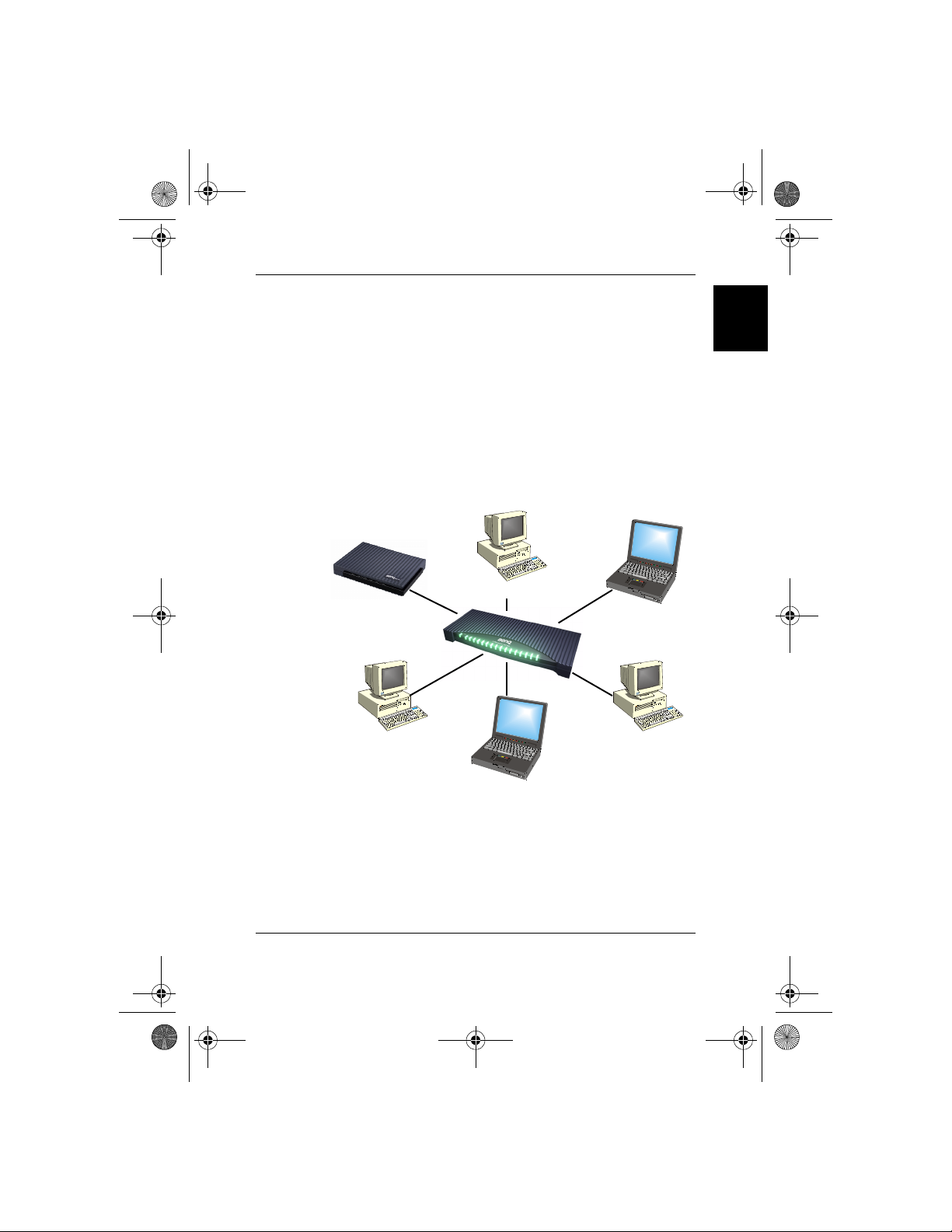
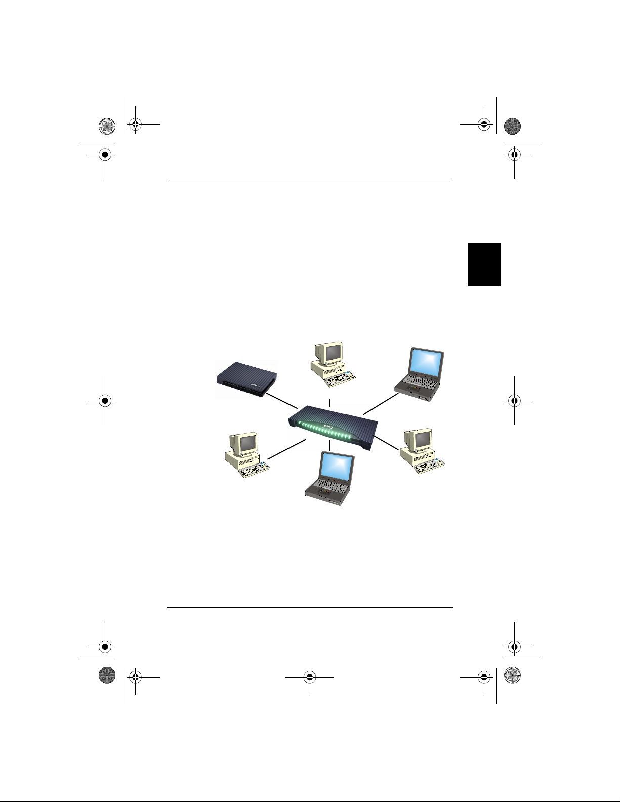
This SP0005/SP0008/SP0016 high performance Fast Ethernet switch provides five/eight/sixteen Fast Ethernet ports to segment network traffic,
extend Fast Ethernet connection distance, and convert data packets
between different transmission speeds. This Fast Ethernet Switch provides shielded RJ-45 ports both with 10Base-T and 100Base-TX Autonegotiation capability and MDI/MDI-X auto crossover. All ports in this
switch support Full-Duplex and Half-Duplex operation modes. The Fast
Ethernet Switch is typically used to segment network traffic that can
improve the network performance by increasing the total bandwidth as
illustrated in Figure 1-1.
ADSL/Cable modem
Linux OS
English
Windows 98/95/2000
Windows Me/XP/NT
Server
Mac OS
Figure 1-1
This Fast Ethernet Switch utilizes stored-and-forward switching architecture that filters and forwards data after the complete data packet is
received and examined to be free of errors. With one set of status LEDs
for each individual port, the switch operation status can be easily monitored. Their slim and compact design allows direct placing on the desktop
or conveniently mounted on the wall or the side of a desk to accommodate cabling consideration.
1. Introduction - 1
Page 4
8PUG.book Page 2 Friday, August 9, 2002 5:32 PM
1.2. Features & Specifications
English
1.2.1. Features
• Compliant with IEEE 802.3 10Base-T Ethernet and 802.3u 100Base-TX
Fast Ethernet Standards.
• Provides 5/8/16 ports for 10Base-T/100Base-TX, standard RJ-45
connectors.
• All RJ-45 ports supports 10Base-T/100Base-TX and Full-Duplex/HalfDuplex Auto-negotiation function.
• Supports MDI/MDI-X auto crossover.
• Supports store-and-forward switching mechanism.
• Plug-and-Play.
• Performs non-blocking full wire speed rate.
• Supports up to 4K/2K/8K (5/8/16 ports) MAC addresses table / hashing
algorithm on address learning.
• Supports Aging function and 802.3x flow control for full Duplex and
collision-based backpressure function for half duplex operation.
• 128K/128K/512K (5/8/16 ports) Bytes buffer memory.
• Automatic address learning, address aging and address migration.
• Simple and economical way to bridge 10Base-T network and 100BaseTX network.
• Front panel status LEDs.
• Desktop size.
• Wall mountable.
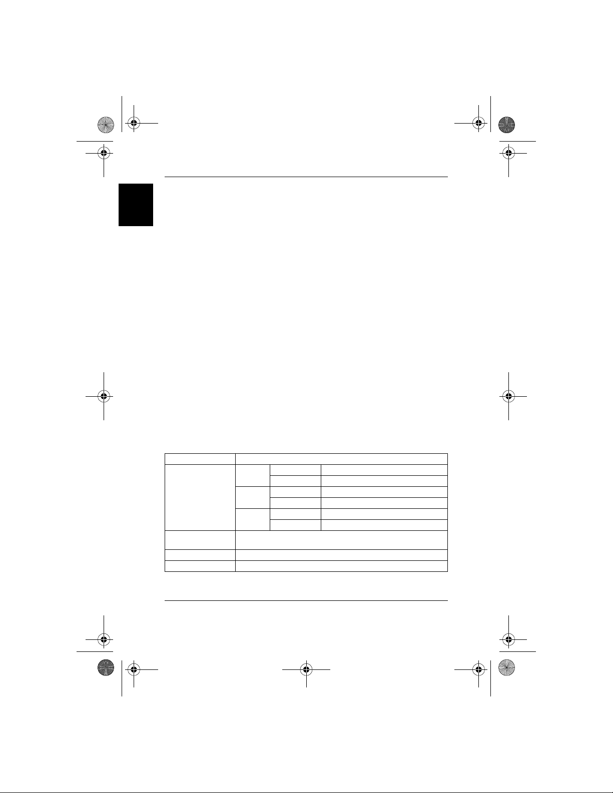
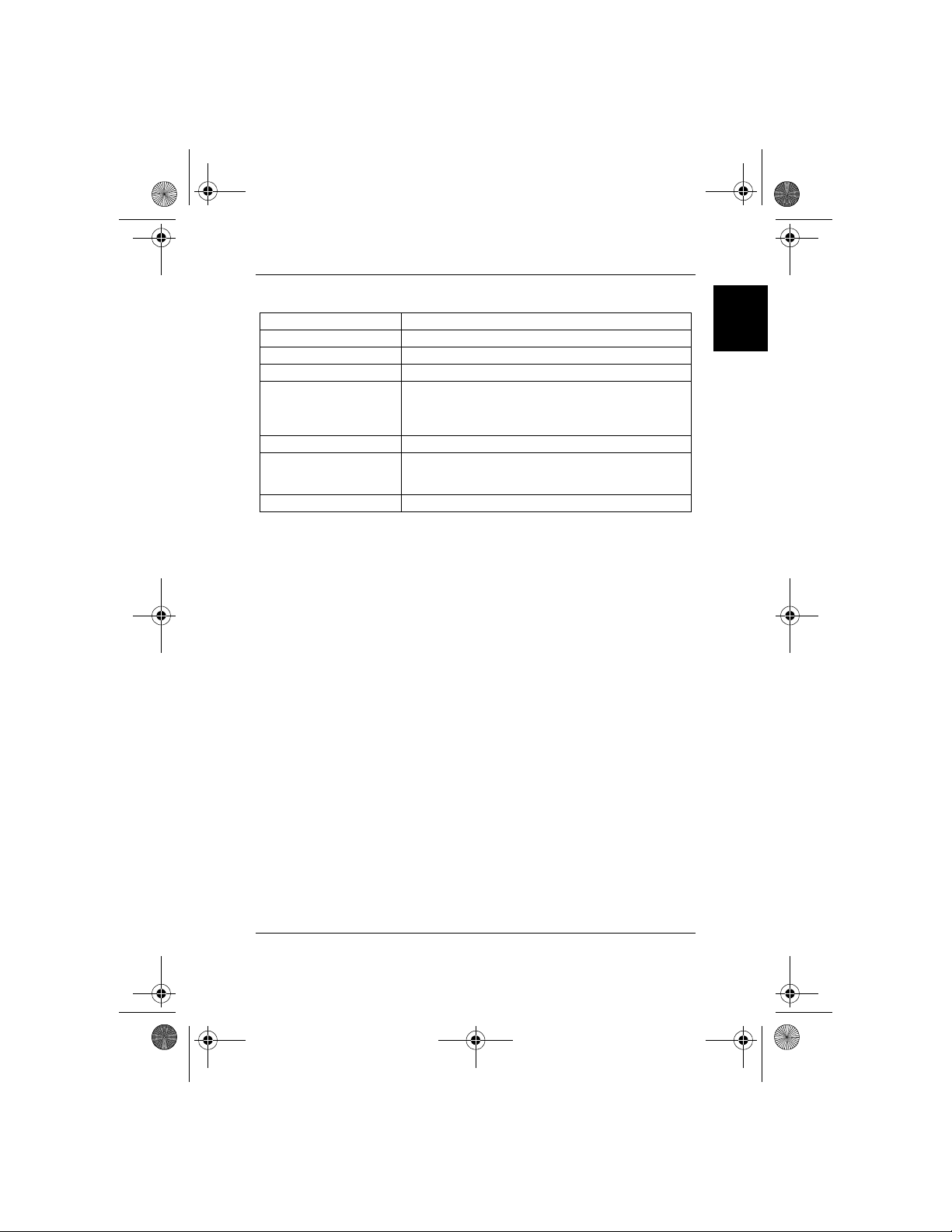
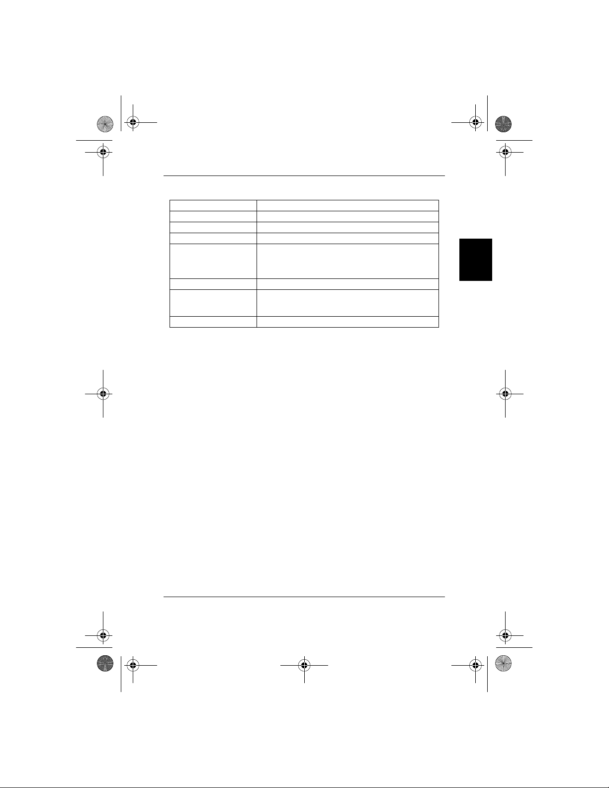
1.2.2. Technical Specifications
Ethernet Standards IEEE 802.3 10Base-T, 802.3u 100Base-TX
Power
LED report
Cable
Switching Method Store-and-forward
Forwarding Rate 14,880pps for 10Mbps; 148,800pps for 100Mbps
100 M
(Green)
10 M
(Yellow)
10Base-T: 2-pair UTP Cat. 3,4,5, up to 100m (328 ft)
100Base-TX: 2-pair UTP Cat. 5, up to 100m (328 ft)
Steady Power On
Off Power Off
Steady (LNK) A valid network connection established
Flashing (ACT) Transmitting or receiving data
Steady (LNK) A valid network connection established
Flashing (ACT) Transmitting or receiving data
1. Introduction - 2
Page 5
8PUG.book Page 3 Friday, August 9, 2002 5:32 PM
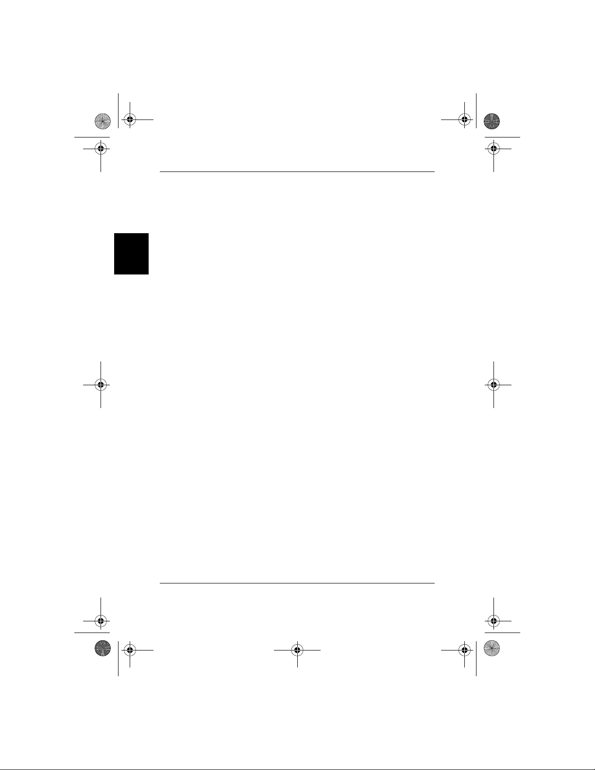
1.2.3. Physical Specifications
AC Input 50-60Hz, External power adapter
Operating Temperature 0°C ~ 50°C (32°F ~ 122°F )
Storage Temperature -20°C ~ 70°C (-4°F ~ 158°F )
Humidity 10% ~ 90% non-condensing
FCC part 15 Class B, CE Mark, VCCI Class B, C-TICK
Emission Compliance
Safety UL/CSA
Dimension
Net Weight 250g (SP0005); 250g (SP0008); 540g (SP0016)
for SP0005 & SP0008
FCC Class A, CE Mark, VCCI Class A, C-TICK
for SP0016
162mm x 103mm x 32mm (SP0005)
162mm x 103mm x 32mm (SP0008)
301mm x 125mm x 32mm (SP0016)
1.3. Terminology
PWR:
This Green LED lights when the power adapter is mounted.
LINK/ACT 10/100:
The Yellow LED lights when there is a valid 10-Base data linked on the
port. And Green LED lights for 100-Base data linked. LED lights blinking
when either 10-Base or 100-Base data is transmitted.
1.4. Package contents
The package should contain the following items:
SP0005/SP0008/SP0016 x 1
AC power adapter x 1
This User’s Guide
English
IF any item is found missing or damaged, please contact your local BenQ
reseller for replacement.
1. Introduction - 3
Page 6
8PUG.book Page 4 Friday, August 9, 2002 5:32 PM
2. Installation
English
2.1. Operating Environment
This switch must be installed and operated within the limits of specified
operating temperature and humidity (see previous section under Specifications).
• Do not place objects on top of the unit.
• Do not obstruct any vents at the sides of the unit.
• Do not position the unit near any heating source such as heater,
radiator, or direct exposure to sun.
• Prevent entering of water and moisture into the unit.
• If necessary, use dehumidifier to reduce humidity.
• Always avoid dust and dirt.
• Allow some space between the product and the surroundings to
facilitate dissipation of heat generated inside the switch.
2.2. Connecting to network devices
The RJ-45 ports on the switch are designed as MDI/MDI-X auto crossover ports which allow using straight-through cables to connect any port
on this switch to network device.
Connect one end of the network cable to the RJ-45 port on the rear
panel, and then connect the other end of the network cable to the RJ-45
port on the network device. Follow the same procedure to connect all
the RJ-45 ports of the switch. The UTP network cables must comply with
EIA/TIA 568 specifications and Category 5 standard for 100Mbps data
transmission and Category 3, 4, 5 for 10Mbps connection. Maximum
length, using UTP cable, between the switch and connected device is 100
meters (328ft). Once the network cable is connected to both ends and
the attached network device is powered on, the green LINK/ACT 10/100
LED should be lit (for 100-Base data linked by auto-negotiation).
2.3. Connecting the power
Connect the output end of the power adapter to the power connector
on the rear panel of the unit. Connect the power adapter to the power
outlet. The green Power LED on the front panel should be lit.
2. Installation - 4
Page 7
8PUG.book Page 5 Friday, August 9, 2002 5:32 PM
3. Trouble Shooting
The SP0005/SP0008/SP0016 can be easily monitored by its LED indicators. Please follow the troubleshooting steps below to solve any problem
you may encounter during installation or implementation of the SP0005/
SP0008/SP0016.
1. Power LED is not lit
Check if the power cord is properly connected to the external power
adapter and the power outlet. Make sure the DC power jack is firmly
plugged into the power socket of the switch.
2. 100M Link/Activity(Green) is not lit when connect to
100 Mbps device
• Check the power switch of the network device attached to the switch;
make sure it is turned ON.
• Check the network cable; make sure it is properly connected to the
switch and the network device.
• Check the network cable; make sure the UTP cables comply with EIA/
TIA 568 and Category 5 specification.
Please perform the following tests
• Please check whether the RJ-45 cable is functional. Replace with
another working cable and see whether the condition can be improved.
• Use another port on the SP0005/SP0008/SP0016. If a link can be
established this way, the first port is faulty. Please contact your local
BenQ dealer for assistant.
• Make sure that all devices are connected to the network.
• Please ensure that the network adapter cards installed in the
workstation or other devices to the switch are in well working
condition.
English
[!] Contact your dealer if problem persists.
3. Trouble Shooting - 5
Page 8

8PUG.book Page i Wednesday, July 31, 2002 10:31 PM
Inhalt
1. Einführung ............................................................................. 1
1.1. Produktübersicht ........................................................................... 1
1.2. Features & technische Daten ...................................................... 2
1.2.1. Features .............................................................................................. 2
1.2.2. Technische Daten ............................................................................. 2
1.2.3. Technische Daten ............................................................................. 3
1.3. Beschreibung ................................................................................... 3
1.4. Packungsinhalt ................................................................................. 3
2. Installation ............................................................................. 4
2.1. Betriebsumgebung ......................................................................... 4
2.2. Anschluss an Netzwerkgeräte .................................................... 4
2.3. Stromanschluss ............................................................................... 4
3. Problembehebung ............................................................... 5
i
Page 9
8PUG.book Page 1 Wednesday, July 31, 2002 10:31 PM
1. Einführung
1.1. Produktübersicht
Dieser SP0005/SP0008/SP0016 High Performance Fast Ethernet Switch
bietet 5/8/16 Fast Ethernet-Schnittstellen für das Segmentieren von
Netzwerkverkehr, für das Erweitern der Fast EthernetVerbindungsentfernung und für das Umwandeln von Datenpaketen in
unterschiedlichen Übertragungsgeschwindigkeiten. Dieser Fast Ethernet
Switch bietet abgeschirmte RJ-45-Schnittstellen mit sowohl 10Base-T als
auch 100Base-TX Auto-Negotiation-Kapazitäten und MDI/MDI-X-AutoCrossover. Alle Schnittstellen des Switches unterstützen die
Betriebsmodi Full-Duplex und Half-Duplex. Der Fast Ethernet Switch
wird normalerweise benutzt, um Netzwerkverkehr zu segmentieren und
so die Netzwerkleistung zu verbessern, indem die gesamte Bandbreite
erhöht wird. Siehe Abb. 1-1.
Windows 98/95/2000
ADSL-/Kabelmodem
Deutsch
Windows Me/XP/NT
Betriebssystem Linux
Betriebssystem Mac
Abb. 1-1
Der Fast Ethernet Switch benutzt einen "Stored-and-Forward"Umschaltmechanismus, der Daten filtert und weiter sendet, nachdem das
komplette Datenpaket empfangen und auf Fehler überprüft wurde. Jede
individuelle Schnittstelle besitzt einen eigenen Satz von Status-LEDs, so
dass der Status der Umschaltoperation leicht erkannt werden kann. Das
schmale und kompakte Gerät lässt sich direkt auf dem Schreibtisch
benutzen oder, abhängig von den Kabelanschlüssen, an einer Wand oder
der Seite eines Tisches anbringen.
1. Einführung - 1
Server
Page 10
8PUG.book Page 2 Wednesday, July 31, 2002 10:31 PM
1.2. Features & technische Daten
1.2.1. Features
• Kompatibel mit IEEE 802.3 10Base-T Ethernet und 802.3u 100Base-TX
Fast Ethernet Standards.
• Bietet 5/8/16 Schnittstellen für 10Base-T/100Base-TX, Standard RJ-45
Anschlüsse.
• Alle RJ-45-Schnittstellen unterstützen 10Base-T/100Base-TX und Full-
Deutsch
Duplex/Half-Duplex Auto-Negotiation-Funktion.
• Unterstützt MDI/MDI-X Auto-Crossover.
• nterstützt "Store-and-Forward"-Umschaltmechanismus.
• Plug-and-Play
• Ermöglicht nicht blockierte volle Kabelgeschwindigkeiten.
• Unterstützt bis zu 4K/2K/8K (5/8/16 Schnittsellen) MAC-
Adressentabelle / Hashing-Algorithmus bei Adressen-Lernen.
• Unterstützt Aging-Funktion und 802.3x Flusskontrolle für Full-Duplex
und Kollision-basierte Backpressure-Funktion für Half-DuplexOperation.
• 128K/128K/512K (5/8/16 Schnittstellen) Bytes-Puffer-Speicher.
• Automatisches Adressen-Lernen, Adressen-Aging und AdressenMigration.
• Einfache und und sparsame Weise zum Überbrücken von 10Base-TNetzwerk und 100Base-TX-Netzwerk.
• Status-LEDs auf Vorderseite
• Schreibtischgröße.
• An Wand montierbar.
1.2.2. Technische Daten
Ethernet-Standards IEEE 802.3 10Base-T, 802.3u 100Base-TX
Ständig Strom ein
Strom
Aus Strom aus
Ständig (LNK)
LED-Anzeige
Kabel
Umschaltmethode Store-and-Forward
Forwarding-Rate 14,880pps für 10Mbps; 148,800pps für 100Mbps
100 M
(Grün)
Aufblinkend (ACT) Daten werden übertragen oder empfangen
Ständig (LNK)
10 M
(Gelb)
Aufblinkend (ACT) Daten werden übertragen oder empfangen
10Base-T: 2-pair UTP Cat. 3,4,5, bis zu 100m (328 ft)
100Base-TX: 2-pair UTP Cat. 5, bis zu 100m (328 ft)
Eine gültige Netzwerkverbindung wurde
erstellt
Eine gültige Netzwerkverbindung wurde
erstellt
1. Einführung - 2
Page 11
8PUG.book Page 3 Wednesday, July 31, 2002 10:31 PM
1.2.3. Technische Daten
Wechselstromeingabe 50-60Hz, Externes Netzteil
Betriebstemperatur 0°C ~ 50°C (32°F ~ 122°F )
Lagertemperatur -20°C ~ 70°C (-4°F ~ 158°F )
Luftfeuchtigkeit 10% ~ 90% nicht kondensierend
FCC Teil 15 Klasse B, CE Mark, VCCI Klasse B, C-TICK
Emissionsrichtlinien
Sicherheit UL/CSA
Abmessungen
Nettogewicht 250g (SP0005); 250g (SP0008); 540g (SP0016)
für SP0005 & SP0008
FCC Klasse A, CE Mark, VCCI Klasse A, C-TICK
für SP0016
162mm x 103mm x 32mm (SP0005)
162mm x 103mm x 32mm (SP0008)
301mm x 125mm x 32mm (SP00016)
1.3. Beschreibung
PWR:
Diese grüne LED leuchtet auf, wenn das Netzteil angeschlossen ist.
LINK/ACT 10/100:
Diese gelbe LED leuchtet auf, wenn gültige 10-Base-Daten an die
Schnittstelle angeschlossen sind. Die grüne LED leuchtet für
angeschlossene 100-Base-Daten auf. LED blinkt, wenn entweder 10-Baseoder 100-Base-Daten übertragen werden.
1.4. Packungsinhalt
Deutsch
Die Packung sollte die folgenden Einzelteile enthalten:
SP0005/SP0008/SP0016 x 1
1 Netzteil
Dieses Benutzerhandbuch
Wenn ein Teil fehlen oder beschädigt sein sollte, kontaktieren Sie bitte
Ihren örtlichen BenQ-Händler, um Ersatz zu erhalten.
1. Einführung - 3
Page 12
8PUG.book Page 4 Wednesday, July 31, 2002 10:31 PM
2. Installation
2.1. Betriebsumgebung
Der Switch muss in einer Umgebung installiert und betrieben werden, in
der die Grenzwerte für Betriebstemperatur und Feuchtigkeit eingehalten
werden (siehe Technische Daten).
• Stellen Sie keine Gegenstände auf die Einheit.
Deutsch
2.2. Anschluss an Netzwerkgeräte
2.3. Stromanschluss
• Verdecken Sie nicht die Lüftungsschlitze auf den Seiten der Einheit.
• Stellen Sie die Einheit nicht in die Nähe einer Hitzequelle, z. B. einen
Heizkörper, oder in direktes Sonnenlicht.
• Vermeiden Sie, dass Wasser oder Feuchtigkeit in die Einheit eindringt
• Benutzen Sie, falls nötig, einen Entfeuchter, um die Luftfeuchtigkeit zu
reduzieren.
• Vermeiden Sie Staub und Schmutz.
• Sorgen Sie für Abstand zwischen dem Gerät und seiner Umgebung, um
die Wärmeableitung vom Inneren des Switches zu erleichtern.
Die RJ-45-Schnittstellen des Switches wurden als MDI/MDI-X-AutoCrossover-Schnittstellen entworfen, die das Benutzen von StraightThrough-Kabeln ermöglichen, um eine beliebige Schnittstelle des
Switches mit einem Netzwerkgerät zu verbinden.
Schließen Sie das eine Ende des Netzwerkkabels an die RJ-45-Schnittstelle
auf der Rückseite an. Schließen Sie dann das andere Ende des
Netzwerkkabels and die RJ-45-Schnittstelle des Netzwerkgeräts an.
Gehen Sie auf die gleiche Weise vor, um alle RJ-45-Schnittstellen des
Switches anzuschließen. Die UTP-Netzwerkkabel müssen mit den EIA/
TIA 568-Werten und dem Kategorie-5-Standard für 100MbpsDatenübertragung sowie Kategorie 3, 4, 5 für 10Mbps-Verbindung
übereinstimmen. Die maximale Länge beim Benutzen eines UTP-Kabels
zwischen dem Switch und angeschlossenem Gerät ist 100 Meter (328ft).
Sobald das Netzwerkkabel an beiden Enden angeschlossen und das
angeschlossene Netzwerkgerät eingeschaltet ist, sollte die grüne LINK/
ACT 10/100 LED (für mit Auto-Negotiation verbundene100-Base-Daten)
aufleuchten.
Schließen Sie das Ausgabeende des Netzteils an den Stromanschluss auf
der Rückseite der Einheit an. Schließen Sie das Netzteil an eine
Netzquelle an. Die grüne Strom-LED auf der Vorderseite sollte
aufleuchten.
2. Installation - 4
Page 13
8PUG.book Page 5 Wednesday, July 31, 2002 10:31 PM
3. Problembehebung
SP0005/SP0008/SP0016 kann mit Hilfe der LED-Anzeigen einfach
überwacht werden. Gehen Sie bitte wie unten angegeben vor, um
Probleme zu beheben, auf die Sie während der Installation oder des
Benutzens von SP0005/SP0008/SP0016 stoßen.
1. Strom-LED leuchtet nicht auf
Überprüfen Sie, ob das Netzkabel korrekt an das externe Netzteil und
die Netzquelle angeschlossen ist. Gehen Sie sicher, dass der
Gleichstromstecker fest in die Buchse des Switches eingesteckt ist.
2. 100M Link/Aktivität (Grün) leuchtet bei Verbindung zu
100 Mbps-Gerät nicht auf
• Überprüfen Sie, ob der Stromschalter des an den Switch angeschlossen
Netzwerkgeräts eingeschaltet ist.
• Überprüfen Sie das Netzwerkkabel; gehen Sie sicher, dass es
ordnungsgemäß an den Switch und das Netzwerkgerät angeschlossen
ist.
• Überprüfen Sie das Netzwerkkabel; gehen Sie sicher, dass die UTPKabel mit den Werten für EIA/TIA 568 und Kategorie 5
übereinstimmen.
Führen Sie bitte die folgenden Tests durch
• Überprüfen Sie, ob das RJ-45-Kabel funktionsfähig ist. Ersetzen Sie es
durch ein anderes funktionierendes Kabel und sehen, ob sich der
Zustand verbessert.
• Benutzen Sie eine andere Schnittstelle von SP0005/SP0008/SP0016.
Wenn eine Verbindung auf diese Weise hergestellt werden kann, ist die
erste Schnittstelle fehlerhaft. Kontaktieren Sie bitte Ihren örtlichen
BenQ-Händler für Hilfe.
• Gehen Sie sicher, das alle Geräte an das Netzwerk angeschlossen sind.
• Gehen Sie sicher, dass die Netzwerk-Adapterkarten, die in die
Workstation installiert sind, oder andere Geräte, die an den Switch
angeschlossen sind, einwandfrei funktionieren.
Deutsch
[!] Kontaktieren Sie Ihren Händler, wenn das Problem weiterhin besteht.
3. Problembehebung - 5
Page 14

8PUG.book Page i Wednesday, July 31, 2002 10:29 PM
Sommarie
1. Introduction ......................................................................... 1
1.1. Présentation .................................................................................... 1
1.2. Fonctionnalités & Caractéristiques ............................................ 2
1.2.1. Fonctionnalités .................................................................................. 2
1.2.2. Caractéristiques techniques ........................................................... 2
1.2.3. Caractéristiques physiques ............................................................. 3
1.3. Terminologie ................................................................................... 3
1.4. Contenu de l’emballage ................................................................ 3
2. Installation ............................................................................. 4
2.1. Environnement d’exploitation ..................................................... 4
2.2. Connexion aux périphériques de réseau ................................. 4
2.3. Connexion de l’alimentation ....................................................... 4
3. Dépannage ............................................................................ 5
i
Page 15

8PUG.book Page 1 Wednesday, July 31, 2002 10:29 PM
1. Introduction
1.1. Présentation
Ce commutateur Fast Ethernet SP0005/SP0008/SP0016 de haute
performance vous fournit cinq/huit/seize ports Fast Ethernet pour
segmenter le trafic du réseau, étendre la distance de connexion d’un
réseau Fast Ethernet, et convertir des paquets de données entre
différentes vitesses de transmission. Ce commutateur Fast Ethernet vous
fournit des ports pour connecteur RJ-45 avec la capacité d’autonégociation 10Base-T et 100Base-TX et traverse automatique MDI/MDIX. Tous les ports de ce commutateur prennent en charge les modes
d’opération bidirectionnel simultané et semi-duplex. Le commutateur
Fast Ethernet est généralement utilisé pour segmenter le trafic du réseau,
ce qui peut améliorer les performances du réseau grâce à une
augmentation de la largeur de bande globale comme il est illustré dans la
Figure 1-1.
Windows 98/95/2000
modem ADSL/Câble
Français
Windows Me/XP/NT
Système
d’exploitation Linux
Figure 1-1
Ce commutateur Fast Ethernet utilise la méthode de commutation de
stockage et d’acheminement (store-and-forward) qui filtre et achemine
les données après que les paquets aient été reçus et examinés pour être
sans erreur. Avec un ensemble de LED d’état pour chaque port, les
opérations du commutateur peuvent être facilement surveillées. D’une
conception fine et compacte, le commutateur peut être aussi bien placé
sur un bureau que monté sur un mur ou sur le bord d’une table de
bureau pour un accès plus direct aux câbles.
1. Introduction - 1
Système
d’exploitation Mac
Serveur
Page 16

8PUG.book Page 2 Wednesday, July 31, 2002 10:29 PM
1.2. Fonctionnalités & Caractéristiques
1.2.1. Fonctionnalités
• Conforme avec les normes IEEE 802.3 10Base-T Ethernet et 802.3u
100Base-TX Fast Ethernet.
• Fournit 5/8/16 ports pour les réseaux 10Base-T/100Base-TX, avec des
connecteurs standards RJ-45.
• Tous les ports RJ-45 prennent en charge les réseaux 10Base-T/100BaseTX et les fonctions d’auto-négociation bidirectionnelle simultanée/semiduplex.
• Prend en charge la traverse automatique MDI/MDI-X.
• Prise en charge de la méthode de stockage et d’acheminement.
• Plug-and-Play.
• Exécute un taux de vitesse non-bloquant plein câble.
Français
• Prise en charge de table d’adresses MAC jusqu’à 4K/2K/8K (5/8/16
ports) / algorithme de hachage pour apprendre les adresses.
• Prise en charge de la fonction datation et du contrôle du flux 802.3x
pour le bidirectionnel simultané et de la fonction de contrôle du flux
aux ports source pour le semi-duplex.
• Mémoire tampon de 128K/128K/512K (5/8/16 ports) Octets.
• Apprentissage, datation et migration automatique des adresses.
• Une manière simple et économique de connecter un réseau 10Base-T à
un réseau 100Base-TX.
• LED d’état sur le panneau avant.
• Taille de bureau.
• Fixable au mur.
1.2.2. Caractéristiques techniques
Normes Ethernet IEEE 802.3 10Base-T, 802.3u 100Base-TX
Alimentation
rapport LED
Câble
Méthode de
commutation
Taux d’acheminement 14,880pps pour 10Mbps; 148,800pps pour 100Mbps
100 M
(Vert)
10 M
(Jaune)
10Base-T: 2-paires de catégorie UTP. 3,4,5, jusqu’à 100m (328 ft)
100Base-TX: 2-paires de catégorie UTP. 5, jusqu’à 100m (328 ft)
Stockage et acheminement
Continu Mise sous tension
Eteint Mise hors tension
Continu (LNK) Une connexion valide au réseau est établie
Clignotant
(ACT)
Continu (LNK) Une connexion valide au réseau est établie
Clignotant
(ACT)
Transmission ou réception de données
Transmission ou réception de données
1. Introduction - 2
Page 17

8PUG.book Page 3 Wednesday, July 31, 2002 10:29 PM
1.2.3. Caractéristiques physiques
Entrée secteur AC 50-60Hz, adaptateur d’alimentation externe
Températures d’opération 0°C ~ 50°C (32°F ~ 122°F )
Température de stockage -20°C ~ 70°C (-4°F ~ 158°F )
Humidité 10% ~ 90% non-condensé
Classe B Partie 15 des FCC, marque CE, Classe B VCCI, C-
Conformité d’émission
Sûreté UL/CSA
Dimensions
Poids net 250g (SP0005); 250g (SP0008); 540g (SP0016)
TICK pour SP0005 & SP0008
Classe A FCC, marque CE, classe A VCCI, C-TICK
pour SP0016
162mm x 103mm x 32mm (SP0005)
162mm x 103mm x 32mm (SP0008)
301mm x 125mm x 32mm (SP0016)
1.3. Terminologie
Alimentation:
Ce LED vert s’allume lorsque l’adaptateur secteur est connecté.
LIEN/ACT 10/100:
Ce LED jaune s’allume lorsqu’un lien de données valide 10-Base est
connecté au port. et le LED vert s’allume lorsque c’est un lien de
données valide 100-Base. Ces LED clignotent lorsque des données 10Base ou 100-Base sont transmises.
1.4. Contenu de l’emballage
Français
L’emballage doit contenir les éléments suivants:
1x SP0005/SP0008/SP0016
1x adaptateur secteur AC
Ce guide d’utilisation
Si l’un des éléments était manquant ou endommagé, veuillez contacter
votre revendeur BenQ pour le faire remplacer.
1. Introduction - 3
Page 18

8PUG.book Page 4 Wednesday, July 31, 2002 10:29 PM
2. Installation
2.1. Environnement d’exploitation
Ce commutateur doit être installé et opéré dans les limites de
température et d’humidité spécifiées (Veuillez vous reporter à la section
précédente et au paragraphe Caractéristiques).
• Ne placez aucun objet sur l’unité.
• Ne bouchez pas les ouvertures latérales de l’unité.
• Ne postionnez pas l’unité près d’une source de chaleur, comme un
radiateur, ou à l’exposition directe du soleil.
• Evitez l’entrée d’eau ou de poussière à l’intérieur de l’unité.
• Si nécessaire, utilisez un déshumidificateur pour réduire l’humidité.
• Eviter toujours la poussière ou les salissures.
Français
2.2. Connexion aux périphériques de réseau
2.3. Connexion de l’alimentation
• Laissez de l’espace aux alentours du produit pour faciliter la dissipation
de la chaleur générée par le commutateur.
Les ports RJ-45 du commutateur sont conçus comme des ports de
traverse automatique MDI/MDI-X qui vous permettent de connecter
directement des câbles d’un périphérique de réseau au port de ce
commutateur.
Connectez l’une des extrémités du câble du réseau au port RJ-45 du
panneau arrière, puis connectez l’autre extrémité du câble du réseau au
port RJ-45 du périphérique de réseau. Suivez la même procédure pour
connecter les autres périphériques aux ports RJ-45 du commutateur. Le
câble de réseau UTP doit être conforme aux spécifications EIA/TIA 568
et à la norme Catégorie 5 pour une transmission des données à 100Mbps
et à la Catégorie 3, 4, 5 pour une connexion à 10Mbps. La longueur
maximum, avec un câble UTP, entre le commutateur et le périphérique
connecté est de 100 mètres (328ft). Une fois le câble du réseau
connecté aux deux extrémités et que le périphérique de réseau est sous
tension, le LED vert LIEN/ACT 10/100 doit s’allumer (pour les données
liées par auto-négociation du 100-Base).
Connectez l’extrémité de sortie de l’adaptateur secteur au connecteur
d’alimentation qui se trouve sur le panneau arrière de l’unité. Connectez
l’adaptateur secteur à la prise de courant. Le LED vert d’alimentation du
panneau avant doit s’allumer.
2. Installation - 4
Page 19

8PUG.book Page 5 Wednesday, July 31, 2002 10:29 PM
3. Dépannage
L’état du SP0005/SP0008/SP0016 peut être facilement surveillé avec ses
indicateurs LED. Veuillez suivre les étapes de dépannage décrites cidessous pour résoudre un problème rencontré lors de l’installation ou de
l’utilisation du SP0005/SP0008/SP0016.
1. Le LED d’alimentation ne s’allume pas
Vérifiez que le cordon d’alimentation est correctement connecté au
connecteur externe de l’adaptateur secteur ainsi qu’à la prise de courant.
Assurez-vous que le connecteur de l’adaptateur est fermement enfoncé
dans le connecteur d’alimentation du commutateur.
2. 100M Lien/Activité(Vert) ne s’allume pas lorsqu’un
périphérique 100 Mbps est connecté
• Vérifiez le commutateur d’alimentation du périphérique de réseau qui
est connecté au commutateur, et assurez-vous qu’il est bien sur la
position Allumé.
• Vérifiez le câble du réseau; assurez-vous qu’il est correctement
connecté au commutateur et au périphérique de réseau.
• Vérifiez le câble du réseau; assurez-vous que les câbles UTP sont
conformes au normes EIA/TIA 568 et Catégorie 5.
Veuillez effectuer les tests suivants
• Veuillez vérifier que le câble RJ-45 fonctionne. Remplacez-le par un
câble qui fonctionne déjà pour voir si les conditions peuvent être
améliorées.
• Utilisez un autre port du SP0005/SP0008/SP0016. Si un lien peut être
établi de cette manière, le port utilisé précédemment est fautif. Veuillez
contacter votre revendeur BenQ pour une assistance.
• Assurez-vous que tous les périphériques sont connectés au réseau.
• Assurez-vous que les cartes de réseau installées dans les postes de
travail ou que les autres périphériques connectés au commutateur
fonctionnent..
Français
[!] Contactez votre revendeur si le problème persiste.
3. Dépannage - 5
Page 20

8PUG.book Page i Friday, August 9, 2002 5:35 PM
Sommario
1. Introduzione .........................................................................1
1.1. Descrizione generale ..................................................................... 1
1.2. Caratteristiche e specifiche tecniche ........................................ 2
1.2.1. Caratteristiche .................................................................................. 2
1.2.2. Specifiche tecniche ........................................................................... 2
1.2.3. Specifiche fisiche ............................................................................... 3
1.3. Terminologia ................................................................................... 3
1.4. Contenuto della confezione ........................................................ 3
2. Installazione ..........................................................................4
2.1. Condizioni ambientali operative ................................................. 4
2.2. Connessione ai dispositivi di rete.r ........................................... 4
2.3. Collegamento dell’alimentatore ................................................. 4
3. Ricerca guasti .......................................................................5
i
Page 21

8PUG.book Page 1 Friday, August 9, 2002 5:35 PM
1. Introduzione
1.1. Descrizione generale
Lo switch Fast Ethernet ad alte prestazioni, tipo SP0005/SP0008/SP0016,
dispone di 5, 8, 16 porte Fast Ethernet per distribuire il traffico Ethernet,
estendere la distanza di connessione, e convertire i pacchetti che entrano
ed escono a diversa velocità di trasmissione. Questo switch Fast Ethernet
ha porte schermate RJ-45 in grado di funzionare sia in 10 Base-T che in
100 Base-TX, con capacità di autonegoziazione autocrossover MDI/MDIX. Tutte le porte di questo switch sono sia Full-Duplex, sia Half-Duplex.
Lo switch Fast Ethernet è tipicamente usato per segmentare il traffico
della rete, migliorandone le prestazioni grazie all’incremento della banda
totale, come illustrato nella figura 1-1.
ADSL/Cable modem
Italiano
Windows 98/95/2000
Windows Me/XP/NT
Linux OS
Figura 1-1
Questo switch Fast Ethernet utilizza l’architettura accumula e inoltra
(store-and-forward) che filtra i dati e li inoltra, dopo che è stato ricevuto
tutto il pacchetto e si è verificato che esso è privo di errori. È facile
monitorare lo stato dello switch, grazie alla presenza di una serie di LED
per ogni porta. Il design compatto e sottile permette di collocarlo
direttamente sulla scrivania, o di montarlo adeguatamente a parete o a
lato di una scrivania, consentendo una facile sistemazione dei cavi di
collegamento.
1. Introduzione - 1
Mac OS
Server
Page 22

8PUG.book Page 2 Friday, August 9, 2002 5:35 PM
1.2. Caratteristiche e specifiche tecniche
1.2.1. Caratteristiche
• Conforme agli standard IEEE 802.3 10Base-T Ethernet e IEEE 802.3u
100Base-TX Fast Ethernet.
• Corredato di 5/8/16 porte per gli standard 10Base-T/100Base-TX, e
connettori standard RJ-45.
• Tutte le porte RJ-45 dispongono di protocolli 10Base-/100Base-TX e di
funzione di autonegoziazione Full-Duplex/Half-Duplex.
• Supporta l’auto crossover MDI /MDI-X.
• Supporta il procedimento accumula e inoltra (store-and-forward).
• Plug-and-Play.
• Funziona alla massima velocità possibile “non blocking”.
• Supporta fino a 4K/2K/8K (5/8/16 porte) di tabelle di indirizzi MAC/
algoritmo d’indirizzamento, per gestire gli indirizzi.
• Supporta la funzione di gestione obsolescenza indirizzi, e il controllo di
flusso 802.3x per il full Duplex, nonché la funzione backpressure, basata
sulla collisione, in half duplex.
• Buffer con memoria di 128K/128K/512K (5/8/16 porte).
• Riconoscimento automatico degli indirizzi, determinazione
Italiano
dell’obsolescenza e trasferimento automatico degli indirizzi.
• Metodo semplice ed economico per collegarsi a reti con protocollo
10Base-T e 100Base-TX.
• LED di stato sul pannello frontale.
• Dimensioni del modello desktop.
• Si può montare a parete.
1.2.2. Specifiche tecniche
Standard Ethernet IEEE 802.3 10Base-T, 802.3u 100Base-TX
Stabile Acceso
Alimenta
zione
Spento Spento
(Stabile (LNK) È stata stabilita una connessione di rete valida
LED di segnalazione
Cavo
Metodo di
commutazione
Vel o c i tà di
trasmissione
100 M
(verde)
Lampeggiante (ACT) In fase di ricezione o trasmissione dati
Stabile (LNK) È stata stabilita una connessione di rete valida
10 M
(Giallo)
Lampeggiante(ACT) In fase di ricezione o trasmissione dati
10Base-T: 2-coppieUTP Cat 3,4,5, fino a 100m
100Base-TX: 2-coppie UTP Cat. 5, fino a 100m
Accumula e inoltra (store-and-forward)
14,880pps per 10Mbps; 148,800pps per 100Mbps
1. Introduzione - 2
Page 23

8PUG.book Page 3 Friday, August 9, 2002 5:35 PM
1.2.3. Specifiche fisiche
Ingresso AC 50-60Hz, alimentatore esterno
Temperatura di
funzionamento
Temperatura di
magazzinaggio
Umidità 10% ~ 90% senza condensa
Compatibilità per i disturbi
emessi
Sicurezza UL/CSA
Dimensioni
Peso netto 250g (SP0005); 250g (SP0008); 540g (SP0016)
0°C ~ 50°C (32°F ~ 122°F )
-20°C ~ 70°C (-4°F ~ 158°F )
FCC parte 15 Class B, Marchio CE, VCCI Classe B, C-TICK
per SP0005 & SP0008
FCC Classe A, Marchio CE, VCCI Classe A, C-TICK
per SP0016
162mm x 103mm x 32mm (SP0005)
162mm x 103mm x 32mm (SP0008)
301mm x 125mm x 32mm (SP0016)
1.3. Terminologia
PWR:
Questo LED si accende quando è collegato l’alimentatore.
LINK/ACT 10/100:
Questo LED si accende di colore giallo quando c’è sulla porta un
collegamento valido 10-Base. Si accende di colore verde per un
collegamento 100-Base data attivo. Il LED lampeggia se si trasmette sia in
10-Base o 100-Base.
1.4. Contenuto della confezione
La confezione deve contenere le seguenti voci:
SP0005/SP0008/SP0016 x 1
Alimentatore AC x 1
Questo manuale dell’utente
Se una di queste voci è mancante oppure danneggiata, rivolgersi al
rivenditore locale dei prodotti BenQ per chiederne la sostituzione.
1. Introduzione - 3
Italiano
Page 24

8PUG.book Page 4 Friday, August 9, 2002 5:35 PM
2. Installazione
2.1. Condizioni ambientali operative
Questo switch deve essere installato e funzionare entro i limiti specificati
di temperatura ed umidità (Consultare la sezione precedente, sotto la
voce Specifiche tecniche).
• Non collocare oggetti sopra di esso.
• Non chiudere le feritoie ai lati..
• Non collocare lo switch vicino a sorgenti di calore come riscaldatori o
radiatori, né esporlo ai raggi del sole.
• Prevenire l’entrata di acqua o di umidità..
• Se necessario, usare deumidificatori per ridurre l’umidità.
• Evitare sempre la polvere e la sporcizia..
• Lasciare sempre dello spazio tra il dispositivo e gli oggetti attorno per
facilitare la dissipazione del calore generato dallo stesso.
2.2. Connessione ai dispositivi di rete.r
Le porte RJ-45 dello switch sono progettate come porte autocrosover
Italiano
MDI/MDI-X che permettono di collegare con cavo diretto qualsiasi porta
ai dispositivi di rete.
Collegare uno dei capi del cavo di rete alla porta nel pannello posterioe e
collegare l’altro capo del cavo di rete alla porta RJ-45 sul dispositivo di
rete. Seguire la stessa procedura per collegare tutte le porte RJ-45 dello
switch. I cavi UTP della rete devono essere conformi alle norme EIA/TIA
568 e agli standard della categoria 5, per la trasmissione di dati a
100Mbps, e delle Categorie 3, 4, 5, per la trasmissione a 10 mbps. La
lunghezza massima del cavo UTP tra lo switch e il dispositivo è di 100
metri. Una volta che il cavo di rete è connesso a tutti e due i capi e il
dispositivo di rete è alimentato, deve essere acceso il LED verde LINK/
ACT 10/100 (per un link 100-Base con autonegoziazione)
2.3. Collegamento dell’alimentatore
Collegare l’uscita dell’alimentatore al connettore sul pannello posteriore
dello switch, collegare l’alimentatore alla presa di rete. Il LED verde sul
pannello frontale deve essere acceso.
2. Installazione - 4
Page 25

8PUG.book Page 5 Friday, August 9, 2002 5:35 PM
3. Ricerca guasti
I dispositivi SP0005/SP0008/SP0016 possono essere facilmente controllati
tramite i LED di segnalazione. Per la ricerca guasti, operare come segue,
al fine di risolvere qualsiasi problema che si possa incontrare durante
l’installazione o l’implementazione di SP0005/SP0008/SP0016.
1. Il LED di alimentazione non è acceso
Controllare che il cavo di alimentazione sia opportunamente collegato
alla rete elettrica. Assicurarsi che la spina di alimentazione sia ben inserita
nella presa dello switch.
2. Il LED verde che segnala attività di link a 100M non è
accesso, quando è connesso a un dispositivo
funzionante a 100 Mbps
• Controllare l’interruttore d’alimentazione del dispositivo di rete
collegato allo switch, assicurarsi che sia acceso.
• Controllare il cavo di rete, assicurarsi che sia opportunamente collegato
allo switch e alla rete.
• Verificare il cavo di rete, assicurarsi che il cavo UTP sia conforme alle
norme EIA/TIA 568 e della categoria 5.
Eseguire i seguenti test:
• Controllare se il cavo RJ-45 funziona. Sostituirlo con un altro cavo e
vedere se la situazione migliora.
• Usare un’altra porta su SP0005/SP0008/SP0016. Se in questo modo il
link funziona, la porta è guasta. Rivolgersi al rivenditore locale dei
prodotti BenQ per assistenza.
• Assicurarsi che tutti i i dispositivi siano collegati alla rete.
• Assicurarsi che le schede di rete, installate nella workstation o in altri
dispositivi verso lo switch, siano in buone condizioni.
Italiano
[!] Rivolgersi al rivenditore se il problema persiste.
3. Ricerca guasti - 5
Page 26

8PUG.book Page i Friday, August 9, 2002 5:37 PM
Contenido
1. Introducción ......................................................................... 1
1.1. Generalidades ................................................................................. 1
1.2. Características y Especificaciones .............................................. 2
1.2.1 Características .................................................................................... 2
1.2.2. Especificaciones Técnicas ................................................................ 2
1.2.3. Especificaciones Físicas .................................................................... 3
1.3. Terminología ................................................................................... 3
1.4. Contenido del paquete ................................................................. 3
2. Instalación ............................................................................. 4
2.1. Entorno Operativo ........................................................................ 4
2.2. Conexión a dispositivos de red .................................................. 4
2.3. Conexión a la red eléctrica ......................................................... 4
3. Resolución de problemas .................................................. 5
i
Page 27

8PUG.book Page 1 Friday, August 9, 2002 5:37 PM
1. Introducción
1.1. Generalidades
Este switch Fast Ethernet SP0005/SP0008/SP0016 de alta performance
provee cinco/ocho/dieciseis puertos Fast Ethernet para segmentar el tráfico de red, extender la distancia de conexionado Fast Ethernet, y convertir paquetes de datos entre diferentes velocidades de transmisión.
Este Switch Fast Ethernet provee puertos RJ-45 blindados tanto en
10Base-T como en 100Base-TX, capacidades de Auto-negociación y auto
crossover MDI/MDI-X. Todos los puertos en este switch soportan
modos de operación Full-Dúplex y Half-Dúplex. El Switch Fast Ethernet
se usa típicamente para segmentar tráfico de red a fin de incrementar el
ancho de banda total como se ilustra en la Figura 1-1.
ADSL/Cable modem
Windows 98/95/2000
Windows Me/XP/NT
Español
Linux OS
Figura 1-1
Este Switch Fast Ethernet utiliza una arquitectura de conmutación storedand-forward que filtra y envía los datos una vez que el paquete completo
de datos es recibido y comprobado que está libre de errores. Con un
conjunto de LEDs para el estado de cada puerto individual, el estado de
operación del switch puede ser fácilmente monitoreado. Su diseño compacto y delgado permite ubicarlos directamente en el escritorio o montarlos convenientemente en la pared o el costado de un escritorio para
acomodar al cableado.
1. Introducción - 1
Mac OS
Servidor
Page 28

8PUG.book Page 2 Friday, August 9, 2002 5:37 PM
1.2. Características y Especificaciones
1.2.1 Características
• Cumple con los estándares Fast Ethernet Standards IEEE 802.3 10BaseT Ethernet y 802.3u 100Base-TX.
• Provee 5/8/16 puertos 10Base-T/100Base-TX, con conectores RJ-45.
• Todos los puertos RJ-45 soportan 10Base-T/100Base-TX y Full-Dúplex/
Half-Dúplex con función de Auto-negociación.
• Soporta MDI/MDI-X auto crossover.
• Soporta mecanismo de switcheo store-and-forward.
• Plug-and-Play.
• Realiza velocidad máxima de cable sin bloqueo.
• Soporta tablas de direcciones MAC hasta 4K/2K/8K (5/8/16 puertos)
algoritmo de hashing en el aprendizaje de direcciones.
• Soporta funciones de Aging y control de flujo para operaciones Full
Dúplex y funciones presión de retorno basadas en colisiones para
operaciones half dúplex en 802.3x.
• Buffer de memoria 128K/128K/512K Bytes (5/8/16 puertos).
• Aprendizaje de direcciones, anticuación de direcciones y migración de
direcciones automáticas.
• Forma fácil y económica de utilizar un bridge entre redes 10Base-T y
100Base-TX.
• LEDs de estado en el panel frontal.
• Tamaño de escritorio.
• Montable en pared.
1.2.2. Especificaciones Técnicas
Español
Estándard Ethernet IEEE 802.3 10Base-T, 802.3u 100Base-TX
Poder
Reportes del LED
Cable
Método de Switcheo Store-and-forward
Tasa de reenvio 14,880pps for 10Mbps; 148,800pps for 100Mbps
100M
(Verde)
10M (Amarillo)
10Base-T: 2-pares UTP Cat. 3,4,5, hasta 100m (328 ft)100Base-TX:
100Base-TX: 2-pares UTP Cat. 5, hasta 100m (328 ft)
Prendida Alimentado
Apagada Sin alimentación
Prendida (LNK)
Intermitente (ACT) Transmitiendo o recibiendo datos
Prendida (LNK)
Intermitente (ACT) Transmitiendo o recibiendo datos
Una conexión válida a la red ha sido
establecida
Una conexión válida a la red ha sido
establecida
1. Introducción - 2
Page 29

8PUG.book Page 3 Friday, August 9, 2002 5:37 PM
1.2.3. Especificaciones Físicas
Voltaje Adaptador de corriente externo, 110-220V 50-60Hz
Temperatura Operativa 0°C ~ 50°C (32°F ~ 122°F )
Temperatura de Almacenaje -20°C ~ 70°C (-4°F ~ 158°F )
Humedad 10% ~ 90% sin condensación
FCC part 15 Class B, CE Mark, VCCI Class B, C-TICK
Cumplimiento de emisiones
Seguridad UL/CSA
Dimensiones
Peso Neto 250g (SP0005); 250g (SP0008); 540g (SP0016)
for SP0005 & SP0008
FCC Class A, CE Mark, VCCI Class A, C-TICK
for SP0016
162mm x 103mm x 32mm (SP0005)
162mm x 103mm x 32mm (SP0008)
301mm x 125mm x 32mm (SP0016)
1.3. Terminología
PWR:
Este LED verde se enciende cuando el adaptador de poder está
conectado.
LINK/ACT 10/100:
El LED Amarillo se enciende cuando hay datos válidos 10-Base conectado
al puerto y el. LED verde se enciende cuando hay datos 100-Base
conectados. Los LED titilan cuando datos 10-Base o 100-Base son transmitidos.
Español
1.4. Contenido del paquete
El paquete debe contener los siguientes ítems:
SP0005/SP0008/SP0016 x 1
Fuente externa AC x 1
Esta Guía del Usuario.
Si algún ítem falta o está dañado, favor contactarse con su revendedor
BenQ local para reemplazo.
1. Introducción - 3
Page 30

8PUG.book Page 4 Friday, August 9, 2002 5:37 PM
2. Instalación
2.1. Entorno Operativo
Este switch debe ser instalado y operado dentro de los límites especificados de humedad y temperatura (vea la sección previa bajo Especificaciones).
• No pose objetos sobre la unidad.
• No obstruya ninguna ventilación en los costados de la unidad.
• No instale la unidad cerca de Fuentes de calor tales como calefactores,
radiadores, etc, ni expuesta directamente a los rayos solares.
• Evite que el agua o la humedad penetren en la unidad.
• De ser necesario, use deshumectantes para reducir la humedad.
• Evite siempre el polvo y la suciedad.
• Prevea cierto espacio entre el producto y objetos circundantes para
facilitar que se disipe el calor generado por el switch.
2.2. Conexión a dispositivos de red
Los puertos RJ-45 del switch están diseñados como puertos MDI/MDI-X
auto crossover lo que permite usar cables estándar para conectar cualquier puerto en este switch a un dispositivo de red.
Conecte un terminal del cable de red al puerto RJ-45 en el panel posterior y luego conecte el otro extremo del cable al puerto RJ-45 del dispositivo de red. Siga el mismo procedimiento para conectar todos los
puertos del switch. Los cables UTP deben cumplir con las especifica-
Español
ciones EIA/TIA 568 y los estándares de Categoría 5 para transmisiones
de datos a 100Mbps y de las Categorías 3, 4, 5 para conexiones a
10Mbps. La distancia máxima utilizando cable UTP, entre el switch y el
dispositivo conectado es de 100 metros (328ft). Una vez que el cable de
red está conectado en ambos extremos y el dispositivo de red conectado
recibe poder, el LED verde LINK/ACT 10/100 debe prenderse (para
datos 100-Base vía auto negociación).
2.3. Conexión a la red eléctrica
Conecte el terminal de la fuente externa al conector de poder en el panel
trasero de la unidad. Conecte el adaptador a la salida de corriente. El
LED verde de poder en el panel frontal debe estar encendido.
2. Instalación - 4
Page 31

8PUG.book Page 5 Friday, August 9, 2002 5:37 PM
3. Resolución de problemas
El SP0005/SP0008/SP0016 puede ser fácilmente monitoreado utilizando
sus indicadores LED. Por favor siga estos pasos para resolver cualquier
problema que pueda encontrar durante la instalación o implementación
del SP0005/SP0008/SP0016.
1. El LED de poder no enciende.
Verifique que el cable de corriente está correctamente conectado a la red
externa. Asegúrese que el conector de DC está firmemente enchufado
en la ficha respectiva del switch.
2. El Led (Verde) 100M Link/Activity no enciende cuando
se conecta a un dispositivo 100 Mbps.
• Revise el interruptor del dispositivo conectado, verifique que esté
encendido (ON).
• Revise el cable de red; asegúrese que esté conectado correctamente
tanto al switch como al dispositivo de red.
• Revise el cable de red; asegúrese que los cables UTP cumplen con las
especificaciones EIA/TIA 568 y la Categoría 5.
Por favor conduzca las siguientes pruebas:
• Por favor revise que el cable RJ-45 funciona. Reemplácelo con otro
cable que sí funciona y vea si la condición mejora.
• Use otro Puerto en el SP0005/SP0008/SP0016. Si se puede establecer
un link de esta forma, entonces el puerto anterior falla. Por favor
contáctese con su distribuidor BenQ para asistencia.
• Asegúrese que todos los dispositivos están conectados a la red.
• Por favor asegúrese que todas las tarjetas de red instaladas en la
estación de trabajo u otros dispositivos de la red están en buenas
condiciones operativas.
Español
[!] Contacte a su distribuidor si el problema continúa.
3. Resolución de problemas - 5
Page 32

8PUG.book Page i Friday, August 9, 2002 5:36 PM
Índice
1. Introdução ............................................................................1
1.1. Produto ............................................................................................ 1
1.2. Funções & Especificações ............................................................. 2
1.2.1. Características ................................................................................... 2
1.2.2. Especificações Técnicas ................................................................... 2
1.2.3. Especificações Físicas ....................................................................... 3
1.3. Terminologia ................................................................................... 3
1.4. Conteúdo do Pacote: .................................................................... 3
2. Instalação ..............................................................................4
2.1. Ambiente de Operação ................................................................ 4
2.2. Conectando em Dispositivos de Rede ..................................... 4
2.3. Conectando a Alimentação ......................................................... 4
3. Resolvendo Problemas ...................................................... 5
i
Page 33

8PUG.book Page 1 Friday, August 9, 2002 5:36 PM
1. Introdução
1.1. Produto
Este switch Fast Ethernet SP0005/SP0008/SP0016 de alta performance
possui cinco/oito/dezesseis portas Fast Ethernet para segmentar o
tráfego da rede, estender a distância de conexão Fast Ethernet e converter pacotes de dados entre diferentes velocidades de transmissão.
Este switch Fast Ethernet possui portas RJ45 blindadas, ambas com
10Base-T e 100Base-TX com capacidade de auto-negociação, e com
"crossover" automático MDI/MDIX. Todas as portas do switch suportam
modos de operação "Full-Duplex" e "Half-Duplex". O switch Fast Ethernet é utilizado tipicamente para segmentar o tráfego da rede o que pode
melhorar a performance da rede através do aumento da banda total
como ilustrado na figura 1.1.
ADSL/Cable modem
Windows 98/95/2000
Windows Me/XP/NT
SO Linux
SO Mac
Figura 1.1
Este switch Fast Ethernet utiliza arquitetura de comutação "store-andforward" que filtra e envia os dados após recepção completa do pacote e
verificação de erro. Com um conjunto de LEDs de estado individual para
cada porta, o estado de operação do switch pode ser facilmente monitorado. O projeto de baixo perfil e compacto permite sua instalação sobre
a mesa de trabalho ou convenientemente montado na parede ou no lado
da mesa, para acomodar o cabeamento.
1. Introdução - 1
Servidor
Português
Page 34

8PUG.book Page 2 Friday, August 9, 2002 5:36 PM
1.2. Funções & Especificações
1.2.1. Características
• Compatível com os padrões IEEE802.3 Ethernet 10Base-T e IEEE803.3u
Fast Ethernet 100Base-TX.
• 5/8/16 portas 10/100Base-TX, conector padrão RJ45.
• Auto-negociação para 10Base-T/100Base-TX e "half/full" duplex em
todas as portas RJ45.
• Detecção automática MDI/MDIX.
• Suporte a mecanismo de comutação "store-and-forward".
• "Plug-and-Play" .
• Realiza transferências "non-bloking" a velocidade "wire speed".
• Tabela suporta até 4K/2K/8K (5/8/16 portas) endereços MAC/
algoritmo de "hashing" na aprendizagem de endereços.
• Suporte a função "Aging", controle de fluxo 802.3x para "full Duplex" e
função "backpressure" baseada em colisão para operação "half duplex".
• "Buffer" de memória de 128K/128K/512K (5/8/16 portas).
• Aprendizagem, expiração e migração automática de endereços.
• Modo simples e econômico de interligação entre redes 10Base-T e
100Base TX.
• LEDs frontais de estado.
• Tamanho de mesa.
• Montagem em parede.
1.2.2. Especificações Técnicas
Padrão Ethernet IEEE 802.3 10Base-T, 802.3u 100Base-TX
Aceso Ligado
Apagado Desligado
Aceso (LNK) Modo 100M
Piscando (ACT) Transmitindo ou recebendo dados.
Aceso (LNK) Conexão válida de rede estabelecida.
Piscando (ACT) Transmitindo ou recebendo dados.
Português
LED's
Cabo
Método de Comutação
Taxa de
Tr an s m i ss ã o
Alimentação
100M
(Verde)
10M
(Amarelo)
10Base-T: 2-pares UTP Cat. 3,4,5 até 100m
100Base-TX: 2-pares UTP Cat. 5, até 100m
Store-and-forward
14.880pps para 10Mbps
148.800pps para 100Mbps
1. Introdução - 2
Page 35

8PUG.book Page 3 Friday, August 9, 2002 5:36 PM
1.2.3. Especificações Físicas
Alimentação Adaptador de alimentação externa 50 - 60 Hz
Temperatura de operação 0°C ~ 50°C (32°F ~ 122°F )
Temperatura de
armazenamento
Umidade em operação 10%~90% não condensado
Compatibilidade para
emissões eletromagnéticas
Segurança UL/CSA
Dimensões
Peso líquido 250g (SP0005); 250g (SP0008); 540g (SP0016)
-20°C ~ 70°C (-4°F ~ 158°F )
FCC parte 15 Classe B, CE Mark, VCCI Classe B, C-tick para
SP0005 e SP0008
FCC parte 15 Classe A, CE Mark, VCCI Classe A, C-tick para
SP0016
162mm x 103mm x 32mm (SP0005)
162mm x 103mm x 32mm (SP0008)
301mm x 125mm x 32mm (SP0016)
1.3. Terminologia
PWR:
O LED verde que acende quando o adaptador de alimentação é
conectado.
LINK/ACT 10/100:
O LED amarelo acende quando existe uma conexão 10Base-T válida na
porta. O LED verde que acende para conexão de dados 100Base-TX. Os
LEDs piscam quando os dados são transmitidos em 10Base-T ou
100Base-TX.
1.4. Conteúdo do Pacote:
SP0005/SP0008/SP0016 x 1
Adaptador de Alimentação CA x 1
Este Guia do Usuário
Se algum destes itens estiver faltando ou danificado, favor entrar em contato com o revendedor BenQ local para substituição.
1. Introdução - 3
Português
Page 36

8PUG.book Page 4 Friday, August 9, 2002 5:36 PM
2. Instalação
2.1. Ambiente de Operação
Este switch deve ser instalado e operado dentro dos limites especificados
de temperatura e umidade (ver seção anterior - especificações).
• Não colocar objetos sobre a unidade.
• Não obstruir as entradas de ar laterais da unidade.
• Não posicionar a unidade próxima a fontes de calor, como
aquecedores, radiadores, ou exposição direta ao sol.
• Prevenir contra a entrada de água e poeira na unidade.
• Se necessário, instalar um de-umidificador para reduzir a umidade.
• Sempre evitar poeira e sujeira.
• Deixar um espaço entre o produto e as imediações para facilitar
dissipação do calor gerada dentro do switch.
2.2. Conectando em Dispositivos de Rede
As portas RJ45 do switch foram projetadas para auto cruzamento MDI/
MDX que permite utilizar cabos diretos para conectar qualquer porta
deste switch em dispositivos de rede.
Conectar uma extremidade do cabo de rede no conector RJ45 do painel
frontal, e conectar a outra extremidade do cabo de rede na porta RJ45
do dispositivo de rede. Seguir o mesmo procedimento para conectar
todas as portas RJ45 do switch. O cabo UTP de rede precisa ser compatível com as especificações EIA/TIA 568 Categoria 5 para transmissão a
100Mbps e Categoria 3, 4, 5 para conexões a 10Mbps. O comprimento
máximo de cabo UTP entre o switch e o dispositivo conectado é de 100
metros. Quando o cabo estiver conectado nas duas extremidades e o
dispositivo de rede estiver ligado, o LED verde LINK/ACT 10/100 de
acender (para conexões de dados 100-Base através da auto negociação).
Português
2.3. Conectando a Alimentação
Conectar a saída do adaptador CA no conector de alimentação na
traseira da unidade. Conectar o adaptador na tomada. O LED verde de
alimentação no painel frontal deve acender.
2. Instalação - 4
Page 37

8PUG.book Page 5 Friday, August 9, 2002 5:36 PM
3. Resolvendo Problemas
O SP0005/SP0008/SP0016 pode ser facilmente monitorado pelos LEDs
indicadores. Seguir os passos seguintes para resolver qualquer problema
que aparecer durante a instalação e implementação do SP0005/SP0008/
SP0016.
1. LED de Alimentação não acende
Verificar se o cabo de alimentação está conectado corretamente no
adaptador CA externo e na tomada da parede. Verificar que o conector
CC esteja firmemente conectado na entrada de alimentação do switch.
2. LED 100M Link/Activity (verde) não acende quando
conectado em um dispositivo de 100Mbps.
• Verificar a alimentação do dispositivo de rede ligado no switch,
certificar-se de que esteja ligado.
• Verificar o cabo de rede; certificar-se de que esteja conectado
corretamente no switch e no dispositivo de rede.
• Verificar o cabo de rede; certificar-se de que o cabo UTP seja
compatível com a norma EIA/TIA 568 especificação categoria 5.
Favor realizar os seguintes testes:
• Verificar se o cabo RJ45 está bom. Substituir por outro cabo que esteja
funcionando e ver se a condição pode ser melhorada.
• Utilizar outra porta do SP0005/SP0008/SP0016. Se a conexão puder ser
estabelecida desta forma, a porta anterior está com problema. Contatar
o revendedor local da Benq para assistência.
• Certificar-se que todos os dispositivos estejam conectados na rede.
• Favor certificar-se que a interface de rede instalada na estação de
trabalho ou outro dispositivo esteja em boas condições de operação.
Português
[!] Contatar o revendedor se os problemas persistirem.
3. Resolvendo Problemas - 5
Page 38

8PUG.book Page i Friday, August 9, 2002 5:32 PM
Inhoudsopgave
1. Inleiding ................................................................................. 1
1.1. Overzicht van het product .......................................................... 1
1.2. Eigenschappen & specificaties ...................................................... 2
1.2.1. Eigenschappen ................................................................................... 2
1.2.2. Technische specificaties .................................................................. 2
1.2.3. Fysieke specificaties .......................................................................... 3
1.3. Terminologie ................................................................................... 3
1.4. Inhoud van de verpakking ............................................................ 3
2. Installatie ............................................................................... 4
2.1. Bedrijfsomgeving ............................................................................ 4
2.2. Aansluiting op netwerkapparaten .............................................. 4
2.3. De voeding aansluiten ................................................................... 4
3. Foutzoeken ........................................................................... 5
i
Page 39

8PUG.book Page 1 Friday, August 9, 2002 5:32 PM
1. Inleiding
1.1. Overzicht van het product
Deze SP0005/SP0008/SP0016 hoog presterende snelle ethernetswitch biedt
vijf, acht/zestien snelle ethernetaansluitingen om netwerkverkeer te verdelen,
de afstand van het ethernet uit te breiden, en gegevenspakketten te
converteren tussen de verschillende verzendsnelheden. Deze snelle
ethernetswitch heeft afgeschermde RJ-45-aansluitingen met automatische
instelling op 10Base-T en 100Base-TX en automatische MDI/MDI-X
crossover. Alle aansluitingen van de switch ondersteunen volduplex en
halfduplex. De snelle ethernetswitch wordt in het algemeen gebruikt om
netwerkverkeer te verdelen en kan de prestaties van het netwerk verbeteren
door de totale bandbreedte te verhogen, zoals u ziet in afbeelding 1-1.
ADSL/Kabelmodem
Windows 98/95/2000
Windows Me/XP/NT
Linux OS
Mac OS
Afbeelding 1-1
Deze snelle ethernetswitch gebruikt een schakelarchitectuur met opslag en
doorzenden, waarmee na ontvangst van een volledig gegevenspakket de
gegevens worden gefilterd, doorgestuurd en gecontroleerd op fouten. Met
een stel toestand-LEDs voor iedere aansluiting kan de bedrijfstoestand van de
switch gemakkelijk gecontroleerd worden. Door het compacte ontwerp kan
de switch direct op een bureau worden geplaatst, aan de muur worden
gehangen of aan de zijkant van een bureau, zonder problemen met de
bekabeling.
1. Inleiding - 1
Server
Nederlands
Page 40

8PUG.book Page 2 Friday, August 9, 2002 5:32 PM
1.2. Eigenschappen & specificaties
1.2.1. Eigenschappen
• Voldoet aan de standaard IEEE 802.3 10Base-T Ethernet en 802.3u 100Base-TX
snel ethernet.
• Biedt 5/8/16 aansluitingen voor 10Base-T/100Base-TX, standaard RJ-45-
connectors.
• Alle RJ-45-aansluitingen ondersteunen 10Base-T/100Base-TX en volduplex/
halfduplex met automatische overschakeling.
• Ondersteunt automatische MDI/MDI-X crossover.
• Ondersteunt een schakelmechanisme met opslag en doorsturen.
• Plug-and-Play.
• Met niet-blokkerend gebruik van de kabelcapaciteit.
• Ondersteunt een tabel met maximaal 4K/2K/8K (5/8/16 aansluitingen) MAC-
adressen en een hash-algoritme om de adressen te leren.
• Ondersteunt verouderingsfunctie en 802.3x-besturing voor volduplex en op
botsingen gebaseerde terugdrukfunctie voor halfduplex.
• 128K/128K/512K (5/8/16 aansluitingen) bytes buffergeheugen.
• Automatisch leren van adressen, adresverouderinge en adresmigratie.
• Eenvoudige en economische manier om een brug te maken tussen een 10Base-T
netwerk en een 100Base-TX netwerk.
• Toestand-LEDs op het voorpaneel.
• Bureaugrootte.
• Kan op de muur worden gemonteerd.
1.2.2. Technische specificaties
Ethernet-standaarden IEEE 802.3 10Base-T, 802.3u 100Base-TX
Vo ed in g
100 M
LED-verslag
Kabel
Schakelmethode Opslaan en doorsturen
Doorstuursneleheid 14 880p/s voor 10MB/s; 148 800p/s voor 100M/s
(Groen)
10 M
(Geel)
10Base-T: 2-paar UTP Cat. 3,4,5, maximaal 100m (328 voet)
100Base-TX: 2-paar UTP Cat. 5, maximaal 100m (328 voet)
Nederlands
Constant Ingeschakeld
Uit Uitgeschakeld
Constant (LNK)
Knipperend
(ACT)
Constant (LNK)
Knipperend
(ACT)
Er is een geldige netwerkverbinding tot stand
gekomen
Gegevens worden verzonden of ontvangen
Er is een geldige netwerkverbinding tot stand
gekomen
Gegevens worden verzonden of ontvangen
1. Inleiding - 2
Page 41

8PUG.book Page 3 Friday, August 9, 2002 5:32 PM
1.2.3. Fysieke specificaties
Netvoeding 50-60Hz, Extern voedingsapparaat
Bedrijfstemperatuur 0°C ~ 50°C (32°F ~ 122°F )
Opslagtemperatuur -20°C ~ 70°C (-4°F ~ 158°F )
Vochtigheid 10% ~ 90% niet condenserend
FCC deel 15 klasse B, CE Mark, VCCI klasse B, C-TICK
Emissiecompliantie
Veiligheid UL/CSA
Afmeting
Gewicht 250g (SP0005); 250g (SP0008); 540g (SP0016)
voor SP0005 & SP0008
FCC klasse A, CE Mark, VCCI klasse A, C-TICK
voor SP0016
162mm x 103mm x 32mm (SP0005)
162mm x 103mm x 32mm (SP0008)
301mm x 125mm x 32mm (SP0016)
1.3. Terminologie
PWR:
Deze groene LED brandt als de voeding in geschakeld is.
LINK/ACT 10/100:
De gele LED brandt als er een geldig netwerkapparaat, werkend met 10-Base,
op de aansluiting is aangesloten. De groene LED brandt bij 100-Base. De
LEDs knipperen als er gegevens worden verzonden, 10-Base of 100-Base.
1.4. Inhoud van de verpakking
De verpakking moet de volgende artikelen bevatten:
SP0005/SP0008/SP0016 x 1
Voedingsapparaat x 1
Deze handleiding
Ontbreekt er een voorwerp of is het beschadigd, neem dan contact op met
uw BenQ-leverancier voor vervanging.
1. Inleiding - 3
Nederlands
Page 42

8PUG.book Page 4 Friday, August 9, 2002 5:32 PM
2. Installatie
2.1. Bedrijfsomgeving
Deze switch moet geïnstalleerd en gebruikt worden binnen de grenzen van
de opgegeven bedrijfstemperatuur en -vochtigheid (zie hiervoor onder
Specificaties).
• Zet geen voorwerpen op het apparaat.
• Blokkeer geen ventilatiegaten aan de zijkant van het apparaat.
• Plaats het apparaat niet bij een warmtebron zoals een kachel of radiator,
en stel het niet bloot aan direct zonlicht.
• Pas op dat er geen water of vocht in het apparaat komt.
• Gebruik zonodig een middel om de vochtigheid te verminderen.
• Vermijd altijd stof en vuil.
• Zorg voor ruimte tussen het product en de omgeving, zodat de warmte
in de switch gemakkelijk kan dissiperen.
2.2. Aansluiting op netwerkapparaten
De RJ-45-aansluitingen op de switch zijn ontworpen als MDI/MDIX
autocrossover-aansluitingen waardoor standaardkabels kunnen worden
gebruikt om de aansluitingen van de switch met netwerkapparaten te
verbinden.
Sluit het ene uiteinde van de netwerkkabel aan op de RJ-45-aansluiting op het
voorpaneel en het andere op de RJ-45-aansluiting op het netwerkapparaat.
Volg dezelfde procedure voor alle RJ-45-aanslutingen op de switch. De UTPkabels moeten voldoen aan de specificaties van EIA/TIA 568 en de standaard
Categorie 5 voor gegevensuitwisseling met 100MB/s en aan de Categorie 3, 4,
5 voor 10MB/s. Maximale lengte, bij gebruik van UTP-kabel, tussen de switch
en aangesloten apparaten is 100 meter (328 voet). Is de netwerkkabel aan
weerszijden aangesloten en het aangesloten apparaat ingeschakeld, dan moet
de LED oplichten (voor 100-Base geschiedt dat door automatische
onderhandeling).
2.3. De voeding aansluiten
Sluit het voedingsapparaat aan op de voedingsconnector op de achterzijde
van het apparaat. Steek de stekker in het stopcontact. Het groene lampje op
het voorpaneel moet nu branden.
Nederlands
2. Installatie - 4
Page 43

8PUG.book Page 5 Friday, August 9, 2002 5:32 PM
3. Foutzoeken
De SP0005/SP0008/SP0016 is eenvoudig te controleren door de LEDs. Volg
de instructies hieronder om een probleem op te lossen dat mocht optreden
tijdens de installatie of implementatie van de SP0005/SP0008/SP0016.
1. VoedingsLED brandt niet
Controleer of de voedingskabel goed is aangesloten op het stopcontact en op
het voedingsapparaat. Controleer of de kabel van het voedingapparaat stevig
op de switch is aangesloten.
2. 100M Link/Activitei(Groen) brandt niet bij verbinding
met een apparaat dat werkt met 100 MB/s
• Controleer de netschakelaar van het netwerkapparaat dat op de switch
is aangesloten. Deze moet AAN-staan.
• Controleer of de netwerkkabel goed is aangesloten op de switch en het
netwerkapparaat.
• Controleer de UTP-netwerkkabel, hij moet voldoen aan de specificaties
van EIA/TIA 568 en Categorie 5.
Voer de volgende tests uit
• Controleer of de RJ-45-kabel goed functioneert. Vervang hem door een
andere kabel en kijk of dat de situatie verbetert.
• Gebruik een andere aansluiting van de SP0005/SP0008/SP0016. Werkt
het dan wel, dan was de eerste aansluiting defect. Neem contact op met
uw BenQ-leverancier voor hulp.
• Controleer of alle apparaten op het netwerk aangesloten zijn.
• Controleer dat de netwerkkaart in het werkstation of ander apparaat
goed geïnstalleerd en goed functioneert.
[!] Neem contact op met uw leverancier als het probleem nog niet is
opgelost.
3. Foutzoeken - 5
Nederlands
Page 44

Warranty.fm Page 1 Friday, August 9, 2002 6:16 PM
BenQ Network Products Limited Warranty
A. LIMITED WARRANTY
BenQ Corporation (“BenQ”) warrants the BenQ network product you
have purchased from BenQ or from an BenQ Authorized Reseller to be
free from defects in materials and workmanship under normal use
during the warranty period of one year from the date of purchase.
Your original purchase invoice (sales receipt), showing the date of
purchase of the network product, is your proof of the date of purchase.
This warranty extends only to you, the original Purchaser. It is not transferable to anyone who subsequently purchases, leases or otherwise
obtains the network product from you.
During the warranty period, BenQ will, at no additional charge, repair or
replace defective parts with serviceable used parts that are equivalent
to new par ts in performance. All exchanged parts and network product replaced under this warranty will become the property of BenQ.
There will be no charge for labor or parts during the one-year warranty
period from the date of purchase.
To ensure timely response to a service request, please complete
and detach the BenQ Warranty Registration Card, then return
it together with a copy of your sales receipt to BenQ within ten
(10) calendar days after date of purchase by end user.
In the event the network product exhibits a defect in material or workmanship within the warranty period, BenQ will provide the warranty services applicable to the network product as defined below.
B. WARRANTY LIMITATION; EXCLUSIONS; EXCLU-
SIVE REMEDIES
The Limited Warranty does not extend to any network product not purchased from BenQ or from an BenQ Authorized Reseller. This limited
warranty also does not extend to any network product that has been
damaged or rendered defective (a) as a result of use of the network product other than for its normal intended use, failure to use the network
product in accordance with the User's Manual which accompanies the
network product or other misuse, abuse or negligence to the network
product; (b) by the use of parts not manufactured or sold by BenQ; (c) by
modification of the network product; (d) as a result of service by anyone
other than BenQ or an BenQ Authorized Service Provider; (e) improper
BenQ Network Products Limited Warranty - 1
Page 45

Warranty.fm Page 2 Friday, August 9, 2002 6:16 PM
transportation or packing when returning the network product to BenQ
or an authorized Service Provider; or (f) unusual physical or electrical
stress or interference, failure or fluctuation of electrical power, lightening, static electricity, fire or acts of God.
EXCEPT FOR THE WARRANTIES AND CONDITIONS SET FORTH
HEREIN, BENQ DISCLAIMS ALL OTHER WARRANTIES, EXPRESS,
IMPLIED, OR STATUTORY, INCLUDING BUT NOT LIMITED TO THE
IMPLIED WARRANTIES OF MERCHANT ABILITY OR FITNESS FOR A
PARTICULAR PURPOSE. ANY IMPLIED WARRANTIES THAT MAY BE
IMPOSED BY APPLICABLE LAW ARE LIMITED TO THE TERMS OF
THIS LIMITED WARRANTY. IN NO EVENT SHALL BENQ BE LIABLE
FOR ANY INCIDENTAL, SPECIAL OR CONSEQUENTIAL DAMAGES,
INCLUDING BUT NOT LIMITED TO LOSS OF BUSINESS, PROFITS,
DATA OR USE, WHETHER IN AN ACTION IN CONTRACT OR TORT
OR BASED ON A WARRANTY, ARISING OUT OF THE NETWORK
PRODUCT OR ANY SOFTWARE SUPPLIED BY BENQ THAT
ACCOMPANIES THE NETWORK PRODUCT, EVEN IF BENQ HAS
BEEN ADVISED OF THE POSSIBILITY OF SUCH DAMAGES. YOU
AGREE THAT REPAIR, REPLACEMENT OR REFUND, AS APPLICABLE,
UNDER THE WARRANTY SERVICES DESCRIBED HEREIN ARE YOUR
SOLE AND EXCLUSIVE REMEDIES WITH RESPECT TO ANY BREACH
OF THE BENQ LIMITED WARRANTY SET FORTH HEREIN.
Some states do no allow the exclusion or limitation of incidental or consequential damages for consumer products, and some states do not allow
limitations on how long an implied warranty lasts. In such cases, the
exclusions or limitations of this Limited Warranty may not apply to you.
This Limited Warranty gives you specific legal rights. You may also have
other rights that vary from state to state. You are advised to consult
applicable state laws for a full determination of your rights.
C. TECHNICAL SUPPORT
Please visit our support website http://www.BenQ.com, the most frequently asked questions are answered here.
All prices, products, terms & conditions are subject to change without
notice.
BenQ Network Products Limited Warranty - 2
 Loading...