

Page 1

FCC Warning
This equipment has been tested and found to comply with the limits for a Class A digital
device, pursuant to Part 15 of the FCC rules. These limits are designed to provide reasonable
protection against harmful interference when the equipment is operated in a residential
environment. This equipment generates, uses, and can radiate radio frequency energy and, if
not installed and used in accordance with this user's guide, may cause harmful interference to
radio communications. However, there is no guarantee that interference will not occur in a
particular installation.
CE Mark Warning
This is a Class A product. In a domestic environment, this product may cause radio
interference, in which case the user may be required to take adequate measures.
Trademarks
Copyright © 2002 Benq Corporation.
Contents subject to change without prior notice. Benq is a registered trademark of Benq
Corporation. All other trademarks belong to their respective proprietors.
Copyright Statement
No part of this publication may be reproduced in any form or by any means or used to make
any derivative such as translation, transformation, or adaptation without permission from Benq
Corporation.
Page 2

i
Table of Contents
1. Introduction.........................................................1
1.1 Product Overview.......................................................1
1.2 Features and Specifications....................................... 2
1.2.1 Features............................................................................. 2
1.2.2 Technical Specifications..................................................... 2
1.2.3 Physical Specifications ...................................................... 5
1.2.4 Physical Ports.................................................................... 6
1.2.5 Basic Functions.................................................................. 6
1.2.6 VLAN................................................................................ 10
1.2.7 Class-of-Service (CoS) Support ...................................... 14
1.2.8 GVRP............................................................................... 14
1.2.9 IGMP Snooping and IP Multicast Filtering....................... 15
1.2.10 Switch Management...................................................... 16
1.3 Product outlook and LED display............................. 17
1.3.1 Product Outlook............................................................... 17
1.3.2 LED Display..................................................................... 18
1.4 Package contents..................................................... 19
2. Installation......................................................... 20
2.1 Operating Environment ............................................20
2.2. Connecting to Your Network....................................21
2.2.1 Cable Type & Length....................................................... 21
2.2.2 Cabling............................................................................. 22
2.3 Connecting to Power................................................ 23
2.4 Optional module installation.....................................25
Page 3

ii
2.4.1 Gigabit Fiber/Copper Module Installation........................ 25
2.4.2 100FX Fiber Module Installation...................................... 26
3. Switch Management .........................................27
3.1 Management Access Overview................................28
3.2 Administration Console ............................................30
3.3 Web Management.................................................... 32
3.4 SNMP-Based Network Management ....................... 32
3.5 Protocols.................................................................. 33
3.6 Management Architecture........................................ 34
4. Menu-Driven Console Management ................36
4.1 Logging on to the switch........................................... 36
4.2 Switch Management Screen ....................................37
4.3 Basic Management .................................................. 40
4.3.1 Start with Selection Menu................................................ 40
4.3.2 General Management Configurations.............................. 41
4.3.3 LAN Port Configurations.................................................. 43
4.3.4 Console Port Configurations............................................ 49
4.4 Advanced Management ...........................................51
4.4.1 Start with Selection Menu................................................ 51
4.4.2 L2 Switching DataBase.................................................... 54
4.4.3 IP Networking................................................................... 67
4.4.4 Bridging............................................................................ 81
4.4.5 Static Filtering.................................................................. 85
4.4.6 Spanning Tree Functions................................................. 88
4.4.7 SNMP Functions.............................................................. 93
4.4.8 Other Protocols................................................................ 96
Page 4

iii
4.4.9 Port Trunking ................................................................... 99
4.4.10 Port Mirroring............................................................... 101
4.4.11 QoS.............................................................................. 103
4.4.12 File transfer.................................................................. 129
4.5 Logout....................................................................136
4.6 Save Settings.........................................................136
4.7 Restore Default Settings ........................................136
4.8 Reboot....................................................................136
5. Web-Based Browser Management ................137
5.1 Logging on to the switch......................................... 137
5.2 Understanding the Browser Interface.....................139
5.3 Performing File Activities........................................141
5.3.1 Start with Selection Menu.............................................. 141
5.3.2 Saving Setting................................................................ 142
5.3.3 Receive File Via TFTP................................................... 142
5.3.4 Reboot ........................................................................... 143
5.3.5 Logout............................................................................ 144
5.4 Performing Basic Setup Activities .......................... 145
5.4.1 Start with Selection Menu.............................................. 145
5.4.2 General Management Configuration.............................. 146
5.4.3 LAN Port Configuration.................................................. 148
5.4.4 Console Port Configuration............................................ 153
5.5 Performing Advanced Setup Activities................... 156
5.5.1 Start with Selection Menu.............................................. 156
5.5.2 MAC Address Management........................................... 157
5.5.3 IP Networking................................................................. 161
5.5.4 Per Port Statistics .......................................................... 171
Page 5

iv
5.5.5 Bridging.......................................................................... 173
5.5.6 Static MAC Filter............................................................ 174
5.5.7 IP Multicast Group ......................................................... 178
5.5.8 VLAN Perspective.......................................................... 179
5.5.9 Spanning Tree Perspective............................................ 185
5.5.10 SNMP........................................................................... 189
5.5.11 Other Protocols............................................................ 192
5.5.12 Port Trunking ............................................................... 193
5.5.13 Port Mirroring............................................................... 195
5.5.14 QoS.............................................................................. 196
6. SNMP & RMON Management ......................... 212
6.1 Overview................................................................212
6.2 SNMP Agent and MIB-2 (RFC 1213)..................... 213
6.3 RMON MIB (RFC 1757) and Bridge MIB (RFC 1493)
.....................................................................................214
7. Trouble Shooting ............................................ 216
Appendix:............................................................ 217
Ordering Information.................................................... 217
Page 6

1. Introduction
1.1 Product Overview
This manual describes how to install and use the SM2224 Management
Gigabit Switch. This switch introduced here is designed to deliver full
scalability with SNMP/RMON web-based management functions by
providing 24x10/100BASE-TX fixed ports, optional 2x100BASE-FX
and optional 2x1000BASE-SX/LX or 1000BASE-T ports. For the two
100BASE-FX fiber ports, each allows for multi-mode SC, ST, VF-45,
MT-RJ fiber module or single-mode SC fiber module. For the two
Gigabit ports, it allows options of fiber type and wavelength at user’s
discretion. This switch brings a simple answer for today’s complicated
networking environments.
To get the best view of this manual, you should have an understanding of
Ethernet networking basic concepts.
In this manual, you will find:
Features on the switch
Illustrative LED functions
Installation instructions
Management Configuration
SNMP, DHCP, IGMP…
Specifications
1. Introduction-1
Page 7

1.2 Features and Specifications
1.2.1 Features
24x10/100BASE-TX ports with RJ-45 connectors,
Optional 2x100BASE-FX fiber ports, each allows for
multi-mode SC, ST, VF-45, MT-RJ fiber module or single-mode
SC fiber module.
Optional 2x gigabit module slots, each allows for
1000Base-SX/LX fiber module or 1000BASE-T copper module
Auto-negotiation for speed and duplex-mode on all TX ports
Full wire-speed forwarding rate
Store-and-forward mechanism
Back-pressure and IEEE 802.3x compliant flow control
Supports 32K MAC addresses
Provides 2M memory buffer
Front panel reset button
Standard 19” rackmount size, one-unit-height
1.2.2 Technical Specifications
Ethernet Standard IEEE 802.3 10Base-T
IEEE 802.3u 100Base-TX
IEEE 802.3ab 1000Base-T
IEEE 802.3z 1000Base-SX/LX
Switch Method Store-and-Forward
Forwarding rate 14,880pps for 10Mbps
148,800pps for 100Mbps
1,488,000pps for 1000Mbps
1. Introduction-2
Page 8

Cable
10Base-T:
100Base-TX/
1000Base-T
1000Base-SX:
1000Base-LX:
2-pair UTP/STP Cat. 3, 4, 5
2-pair UTP/STP Cat. 5
Both up to 100m (328ft)
62.5/125µm multi-mode fiber
(850nm) Up to 220m
50/125µm multi-mode fiber
(850nm)
Up to 550m
62.5/125µm multi-mode fiber
(1300nm)
Up to 550m
10/125µm single-mode fiber
(1300nm)
Up to 20km
LED Indicators Per unit – Power status
Per port – LNK /ACT, FDX/COL,
10/100M
Per Gigabit port –LNK /ACT,
FDX/COL
VLAN
Port-base VLAN,
802.1Q compliant tagged VLAN, up to 255 groups
TRUNKING
Port trunking is provided by 3 groups. Group 1 & group 2,
each allows up to 4 ports trunking selected from port 1 ~
port 24 while group 3 allows 2 gigabit ports trunking.
1. Introduction-3
Page 9

PORT-SECURITY
Limit number of MAC addresses learned per port
Static MAC addresses stay in the filtering table
PORT-MIRRORING
Port-mirroring provided through any two pair of mirror
and capture ports
COS (IEEE802.1P CLASSIFICATION OF SERVICE)
4-level transmission priorities: 4 queues per output port
Packet transmission scheduled using Weighted Round
Robin (WRR)
User-defined weights
Classification of packet priority can be based on either a
VLAN tag on packet or a user-definable port priority
INTERNETWORKING PROTOCOLS
Bridging: 802.1D Spanning Tree
802.1p/Q – GARP/GVRP
Routing: RIP
RIP-2
DHCP-Relay
ICMP Router Discovery Message
IP Multicast: IGMP Snooping
IP Multicast Packet Filtering
(Maximum of 256 VLANs and IP multicast
1. Introduction-4
Page 10

sessions)
NETWORK MANAGEMENT METHODS
Console port access via RS-232 cable
Telnet remote access
SNMP agent: MIB-2 (RFC1213)
Bridge MIB (RFC1493)
RMON MIB (RFC1757) – statistics,
history, alarm and events
VLAN MIB (802.1Q/RFC2674)
Private MIB
Java applet-based MIB browser
Web browser support based on HTTP server and CGI
parser
Kermit/TFTP software-upgrade capability
1.2.3 Physical Specifications
Power 100~240VAC 50-60Hz
Operating Temperature 0°C ∼ 50°C
Storage Temperature -20°C ∼ 70°C
Operating Humidity 10% ∼ 90% RH
Emission Compliance FCC part 15 Class A, CE
Mark, VCCI, C-tick
Safety UL/CSA
Dimension W 435 mm X D 221 mm X H
44 mm (17.1” X 8.7” X 1.8”).
1. Introduction-5
Page 11

Standard 19” rack-mount size,
one-unit-height.
Net Weight 3.4 kg(7.5lb)
1.2.4 Physical Ports
The Management Gigabit Switch provides 24x10/100Base-TX
fixed ports and optional slots for 100Base-FX, 1000Base-SX/LX
and 1000Base-T ports.
1.2.5 Basic Functions
In general, the switch is responsible for switching both VLAN
tagged and untagged frames from a receiving port to one or
more transmitting ports. The switch performs multiple steps
during the switching process:
l VLAN classification
l Learning
l Filtering
l Forwarding
l Aging
Below is additional information about tasks that the switch
performs during unicast and multicast switching.
UNICAST SWITCHING
VLAN CLASSIFICATION
When the switch receives a frame, it classifies the frame in one
of two ways:
l If the frame is untagged, the switch classifies the frame to an
associated VLAN.
1. Introduction-6
Page 12

l If the frame is tagged, the switch uses the tagged VLAN ID to
identify the broadcasting domain of the frame.
LEARNING
After VLAN classification, the switch checks the <source MAC
address, VLAN> pair in the switching database (SDB) to see
whether the <source MAC address, VLAN> pair is known.
l If it is unknown, the switch inserts the <source MAC address,
VLAN> into the SDB and learns the <source MAC address,
VLAN>.
l If it is known, the switch checks the <source MAC address,
VLAN> for a mismatched port ID. If the port ID associated
with the <source MAC address, VLAN> pair in the SDB is
different than the receiving port, the switch modifies the port
ID in the SDB and modifies its management database (MDB)
accordingly.
1. Introduction-7
Page 13

FILTERING
After learning the address, the switch checks:
l Whether the source port or destination port is in the
forwarding state.
l Whether the source MAC address or destination MAC
address is to be filtered.
l Whether the source port ID is the same as destination port
ID.
If any of these conditions are met, the switch drops the receiving.
Otherwise, it continues with the forwarding process described
below.
FORWARDING
During the forwarding process, the switch checks whether the
<destination MAC address, VLAN> pair is unknown.
l If it is unknown, the switch floods the receiving frame to all
ports in the VLAN, excluding the source port.
l If it is known, the switch forwards the receiving frame to the
port associated with the <destination MAC address, VLAN>
pair. At the same time, the switch ascertains the individual’s
port’s VLAN tagging/untagging configuration and
corresponding VLAN ID to render the appropriate frame
tagging when the frame is ready to be transmitted.
MULTICAST SWITCHING
For multicast switching, the switch checks whether the received
frame is a BPDU. If a BPDU is received, the switch forwards the
frame to the CPU for processing by the spanning tree protocol.
Otherwise, the switch performs the following processes:
VLAN CLASSIFICATION
Same as for unicast switching.
1. Introduction-8
Page 14

LEARNING
Same as for unicast switching.
FILTERING
After learning the address, the switch checks:
l Whether the source port or destination port is not in the
forwarding state.
l Whether the source MAC address or destination MAC
address is to be filtered.
l Whether the source port ID is the same as destination port
ID.
If any of these conditions are met, the switch drops the receiving.
Otherwise, it continues with the forwarding process described
below.
FORWARDING
The switch floods the received multicast frame to all ports that
are in forwarding state within the VLAN, excluding the source
port. At the same time, the switch ascertains the individual port’s
VLAN tagging/untagging configuration and corresponding VLAN
ID to render the appropriate frame tagging when the frame is
ready to be transmitted.
AGING
The switch performs the aging process for the <MAC addresses,
VLAN> pair in the switching database. Once a <MAC address,
VLAN> pair is aged out, the SDB is modified.
SPANNING TREE
The switch supports one Spanning Tree per bridged network.
1. Introduction-9
Page 15

1.2.6 VLAN
A virtual LAN (VLAN) is a network of computers that behave as
if they are connected to the same wire, even though they may
actually be physically located on different segments of a LAN.
VLANs are analogous to a group of end stations, perhaps on
multiple physical LAN segments that are not constrained by their
physical location and can communicate as if they were on a
common LAN.
VLANs are configured through software rather than hardware,
which makes them extremely flexible. One of the biggest
advantages of VLANs is that when a computer is physically
moved to another location, it can stay on the same VLAN
without any hardware reconfiguration.
Because VLANs are not limited by the hardware constraints that
physically connect traditional LAN segments to a network, they
can define a network into various logical configurations. For
example, VLANs can define a network by application. In this
scenario, a company might create one VLAN for multimedia
users and another for email users. VLANs can also define a
network by department. For example, a company might have
one VLAN for its Engineering Department, another for its
Marketing Department, and another for its Account Payable
Department.
VLANs can also be set up according to the organization
structure within a company. For example, the company president
might have his/her own VLAN, the executive staff might have a
different VLAN, and the remaining employees might have yet a
different VLAN.
As these examples show, VLANs offer unparalleled flexibility.
1. Introduction-10
Page 16

The following sections describe how deploying VLANs can
benefit organizations and reduce administration costs.
BROADCAST CONTAINMENT
In traditional networks, traffic broadcasts to all network devices,
whether they are the intended recipients or not. However,
VLANs can be set up to contain only those devices that need to
communicate with each other. As a result, VLANs significantly
reduce network congestion. In addition, VLANs prevent
broadcast storms from causing network meltdown due to
volumes of traffic.
MULTICAST-BASED MULTIMEDIA APPLICATIONS
Multimedia applications, such as interactive training, video
conferencing, and news-video transmissions, require large
amounts of bandwidth. These applications are also extremely
sensitive to variable delays, which are unavoidable on a shared
Ethernet network. By defining a VLAN based on the IP multicast
address for all subscribing members on the VLAN, sufficient
bandwidth will be available for these application, providing true
multimedia on Ethernet.
ENHANCED SECURITY
Because VLANs are self-contained, only the devices within the
same VLAN can communicate with each other. If a device in one
VLAN wants to communicate with a device in another VLAN, the
traffic must go through a router.
1. Introduction-11
Page 17

VLAN MEMBERSHIP
VLAN implementation allows:
l Up to 256 VLANs in one switch.
l VLANs across multiple switches by using explicit or implicit
tagging and the GARP/GVRP protocol defined in
IEEE802.1p and 802.1Q.
l An end station’s network interface card belong to multiple
VLANs.
l A switch port to be associated with multiple VLANs.
DEFINITIONS OF VLAN MEMBERSHIP
VLAN implementation allows VLAN membership to be defined
based on ports. Port-based VLANs are organized by physical
port number. For example, switch ports 1, 2, 4 and 6 can be
grouped on VLAN, while server ports 3, 5, 7 and 8 can be on
another VLAN. Broadcasts from servers within each group
would only go to the members of its own VLAN. This ensures
that broadcast storms cannot cause a network meltdown due to
volumes of traffic.
VLAN MEMBERSHIP LEARNING
Port-based VLAN is defined using a static binding between a
VLAN and its associated ports. The switch’s forwarding decision
is based on the destination MAC address and its associated port
ID. Therefore, to make valid forwarding and flooding decisions,
the switch learns the relationship of the MAC address to its
related port – and thus to the VLAN – at runtime.
REMOTE VLAN LEARNING
In addition to providing network management tools that allow
network administrators to statically add and delete VLAN
member ports, the switch also supports GVRP (GARP VLAN
1. Introduction-12
Page 18

Registration Protocol). GVRP allows for dynamic registration of
VLAN port members within switch and across multiple switches.
Other than supporting dynamic updating of registration entries in
a switch, GVRP is used to communicate VLAN registration
information to other VLAN-aware switches, so that a VLAN
member can cover a wide span of switches on a network.
GVRP allows both VLAN-aware workstations and switches to
issue and revoke VLAN memberships. VLAN-aware switches
register an propagate VLAN membership to all ports that belong
to the active topology of the VLAN.
VLAN CONFIGURATION
The switch provides a Local/Remote Management Console
Interface for VLAN configuration and management An
SNMP-based VLAN MIB is also provided.
INTRA-VLAN COMMUNICATION
The switch supports intra-VLAN communication through
hardware, as described in “Basic Functions” section.
INTER-VLAN COMMUNICATION
The switch supports inter-VLAN communication using
CPU-based routing software.
1. Introduction-13
Page 19

1.2.7 Class-of-Service (CoS) Support
The switch provides four transmit queues on each port, with a
weighted round-robin scheme. These functions can be used to
provide independent priorities for various types of data including
real-time video, real-time voice, and best-effort data.
Priority assignment to packet-based switches is accomplished
through explicit assignment by end stations, which have
applications that require a higher priority than best-effort data.
This mechanism utilizes the IEEE802.1p and 802.1Q tag
structure, which the switch uses to decide priority assignments
for the received packets.
1.2.8 GVRP
In addition to network management tools that allow network
administrators to statically add and delete VLAN member ports,
the routing switch supports GARP VLAN Registration Protocol
(GVRP). GVRP supports dynamic registration of VLAN port
members within a switch and across multiple switches.
In addition to dynamically updating registration entries within a
switch, GVRP is used to communicate VLAN registration
information to other VLAN-aware switches, so that members of a
VLAN can cover a wide span of switches on a network.
GVRP allows both VLAN-aware workstations and switches to
issue and revoke VLAN memberships. VLAN-aware switches
register and propagate VLAN membership to all ports that are
part of the active topology of the VLAN.
1. Introduction-14
Page 20

1.2.9 IGMP Snooping and IP Multicast Filtering
The Internet Group Management Protocol (IGMP) runs between
hosts and their immediately neighboring multicast routers. The
protocol’s mechanisms allow a host to inform its local router that
it wants to receive transmissions addressed to a specific
multicast group.
Routers periodically query the LAN to determine if known group
members are still active. If there is more than one router on the
LAN performing IP multicasting, one of the routers is elected
“querier” and assumes the responsibility of querying the LAN for
group members.
Based on the group membership information learned from the
IGMP, a router can determine which (if any) multicast traffic
needs to be forwarded to each of its “leaf” subnetworks.
Multicast routers use this information, along with a multicast
routing protocol, to support IP multicasting across the Internet.
IGMP provides the final step in an IP multicast packet delivery
service since it is only concerned with the forwarding of multicast
traffic from the local route to group members on directly attached
subnetworks.
Routing switches support IP Multicast Filtering by:
l Passively snooping on the IGMP Query and IGMP Report
packets transferred between IP Multicast Routers and IP
Multicast host groups to learn IP Multicast group members,
and
l Actively sending IGMP Query messages to solicit IP Multicast
group members.
1. Introduction-15
Page 21

The purpose of IP multicast filtering is to optimize a switched
network’s performance, so multicast packets will only be
forwarded to those ports containing multicast group hosts
members and routers instead of flooding to all ports in the
subnet (VLAN).
Routing switches with IP multicast filtering/switching capability
not only passively monitor IGMP Query and Report messages,
DVMRP Probe messages, PIM, and MOSPF Hello messages;
they also actively send IGMP Query messages to learn locations
of multicast routers and member hosts in multicast groups within
each VLAN.
Note, however, IGMP neither alters nor routes any IP multicast
packets. Since IGMP is not concerned with the delivery of IP
multicast packets across subnetworks, an external IP multicast
router is needed if IP multicast packets have to be routed across
different subnetworks.
1.2.10 Switch Management
ADMINISTRATION CONSOLE VIA RS-232 SERIAL PORT
The switch provides an onboard serial port, which allows the
switch to be configured via a directly connected terminal or a
Telnet session.
WEB-BASED BROWSER INTERFACE
The switch also boasts a point-and-click browser-based
interface that lets users access full switch configuration and
functionality from a Netscape or Internet Explorer browser.
1. Introduction-16
Page 22
EXTERNAL SNMP-BASED NETWORK MANAGEMENT
APPLICATION
The switch can also be configured via SNMP.
For more information on switch management, refer to the
“Switch Management” section on page 14.
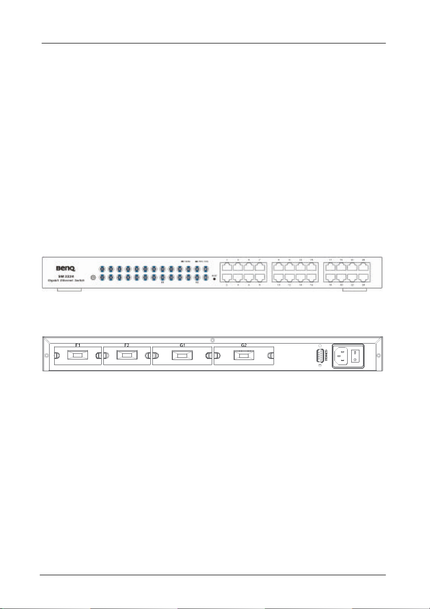
1.3 Product outlook and LED display
1.3.1 Product Outlook
Front View of SM2224
Rear view of SM2224
1. Introduction-17
Page 23

1.3.2 LED Display
LEDs State Indication
Power
(Green)
LNK/ACT
(Port
number)
(Green)
100M
(Green)
FDX/COL
(Yellow)
F1, F2
(Orange)
Steady Power on
Off Power off
A valid network connection
On
Flashing
On 100M mode
Off 10M mode
On
Flashing
Off
On Fiber module connected
Off No Fiber module connected
established.
LNK stands for LINK.
Transmitting or receiving data.
ACT stands for ACTIVITY.
Connection in full duplex mode.
FDX stands for FULL-DUPLEX.
Collision occurred.
COL stands for COLLISION.
Connection in half-duplex mode.
1. Introduction-18
Page 24

1.4 Package contents
When you unpack the product package, you shall find the items
listed below. Please inspect the contents, and report any
apparent damage or missing items immediately to your
authorized reseller.
ü SM2224 x 1
ü This User’s Guide
ü AC power cord x 1
ü RS232 cable x 1
ü Rack mount ears with screws
ü Warranty card
1. Introduction-19
Page 25

2. Installation
This chapter gives step-by-step instructions about how to install the
switch:
2.1 Operating Environment
As with any electric device, you should place the switch where it
will not be subjected to extreme temperatures, humidity, or
electromagnetic interference. Specifically, the site you select
should meet the following requirements:
- The ambient temperature should be between 32 and 122
degrees Fahrenheit (0 to 50 degrees Celsius).
- The relative humidity should be less than 90 percent,
non-condensing.
- Surrounding electrical devices should not exceed the
electromagnetic field (RFC) standards for IEC 801-3, Level 2
(3V/M) field strength.
- Make sure that the switch receives adequate ventilation. Do
not block the ventilation holes on each side of the switch or
the fan exhaust port on the rear of the switch.
- The power outlet should be within 1.8 meters of the switch.
2. Installation -20
Page 26

2.2. Connecting to Your Network
2.2.1 Cable Type & Length
It is necessary to follow the cable specifications below when
connecting the switch to your network. Use appropriate cables
that meet your speed and cabling requirements.
Cable Specifications
Speed Connector
10BASE-T
100BASE-TX
1000BASE-T
1000BASE-SX
(*Wavelength of
850nm)
1000BASE-LX
(*Wavelength of
1300nm)
RJ-45
RJ-45
RJ-45
SC
SC
SC
SC
Port Speed
Half/Full Duplex
10/20 Mbps
100/200 Mbps
1000/2000 Mbps
1000/2000 Mbps
1000/2000 Mbps
1000/2000 Mbps
1000/2000 Mbps
Cable
2-pair UTP/STP
Cat. 3, 4, 5
2-pair UTP/STP
Cat. 5
2-pair UTP/STP
Cat. 5
62.5/125µm
multi-mode
fiber
50/125µm
multi-mode
fiber
62.5/125µm
multi-mode
fiber
10/125µm
single-mode
fiber
Max.
Distance
100 m
100 m
100 m
220 m
550 m
550 m
20 km
2. Installation -21
Page 27

2.2.2 Cabling
Step 1: First, ensure the power of the switch and end devices
is turned off.
<Note> Always ensure that the power is off before any
installation.
Step 2: Prepare cable with corresponding connectors for each
type of port in use.
<Note> To connect two regular RJ-45 ports between switches
or hubs, you need a cross-over cable.
Step 3: Consult Cable Specifications Table on previous page
for cabling requirements based on connectors and
speed.
Step 4: Connect one end of the cable to the switch and the
other end to a desired device.
Step 5: Once the connections between two end devices are
made successfully, turn on the power and the switch is
operational.
2. Installation -22
Page 28

2.3 Connecting to Power
Step 1: Connect the supplied AC power cord to the receptacle
on the back of the switch, and then plug it into a
standard AC outlet with a voltage range from 100 to
240 Vac.
Step 2: Disconnect the power cord if you want to shut down
the switch.
POWER-ON SELF TEST (POST)
The Switch performs its Power-On Self Test (POST) when the
power is switched on. During the POST, the switch CPU will:
l perform a series of diagnostic procedures to make sure the
basic system is functioning integrity
l decompress the main switching software runtime image from
the flash ROM into DRAM area
l begin executing the main switching software
A command line prompts when you press the Esc key on a
terminal connected to the switch serial port during the POST
process. Then you can execute the following options:
DOWNLOAD RUNTIME SOFTWARE FROM SERIAL PORT
This will download the runtime system image to the switch via
the serial port. Before selecting this option, make sure:
l A host system is running a terminal emulation program that
supports the Kermit file transfer protocol.
l The host system’s hard drive has the required binary file that
will be downloaded to the switch.
2. Installation -23
Page 29

CONFIGURE THE SYSTEM
This option lets you modify any configurable parameter in the
switch’s flash ROM before the switch system boots.
RUN MANUFACTURING DIAGNOSTICS
This option is to download the manufacturer’s diagnostics. Refer
to Download Runtime Software for download requirements.
When the file transfer is completed, the target system jumps to
the entry point of the diagnostic program and starts executing
the diagnostic code. The Main Menu of the diagnostic program
appears, where you can initiate tests or obtain system
information. Note that user intervention is not required when a
test runs, unless an error occurs. If an error occurs during
testing, you are given the choice of continuing the diagnostics or
skip the error.
2. Installation -24
Page 30
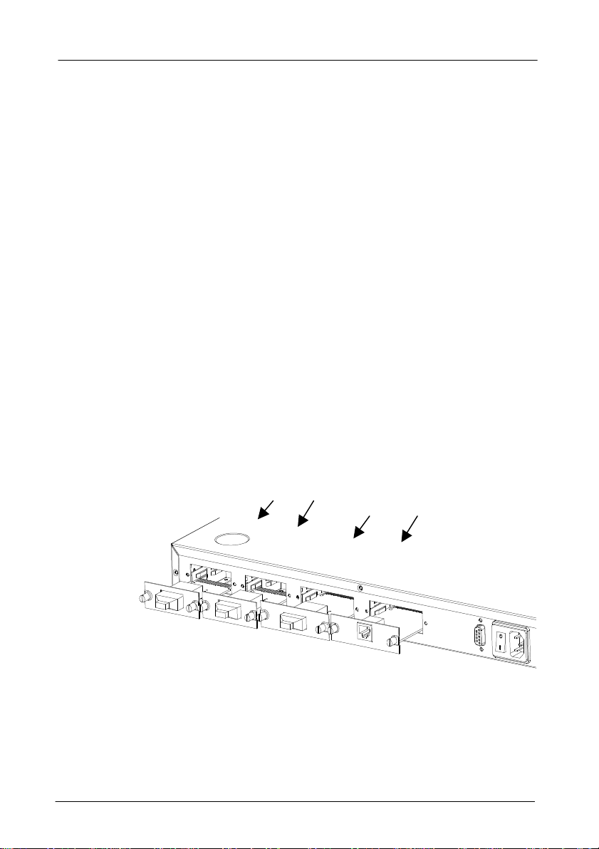
2.4 Optional module installation
2.4.1 Gigabit Fiber/Copper Module Installation
The gigabit module shall be inserted into the expansion
slot located at the rear of the switch.
• Remove the module from the static free container
• Unscrew the cover plate of the expansion slot.
• Remove the plate and keep it for future use when you
decide to remove the module
• With the power off, slide the module into the slot
• Once it is slid in fully, snap in the module to make a
proper connection and fasten the screws
• Turn on the power
• Connect the appropriate fiber that can match the
connector provided
100FX Module Slots
Gigabit Module Slots
2. Installation -25
Page 31

2.4.2 100FX Fiber Module Installation
The 100FX fiber module shall be inserted into the
expansion slot located at the rear of the switch.
Remove the module from the static free container
Set Full Duplex or Half Duplex operation mode by using
J2 jumper.
Full Duplex
Half Duplex
Unscrew the cover plate of the expansion slot.
Remove the plate and keep it for future use when you
decide to remove the module
With the power off, slide the module into the slot
Once it is slid in fully, snap in the module to make a proper
connection and fasten the screws
Turn on the power
2. Installation -26
Page 32

3. Switch Management
This chapter explains the methods that you can use to
configure management access to the switch. It describes
the types of management applications and the
communication and management protocols that deliver data
between your management device (workstation or personal
computer) and the system. It also contains information
about port connection options.
This chapter covers the following topics:
l Management Access Overview
l Key Concepts
l Key Guidelines for Implementation
l Administration Console Access
l Web Management Access
l SNMP Access
l Standards, Protocols, and Related Reading
3. Switch Management -27
Page 33

3.1 Management Access Overview
The switch gives you the flexibility to access and manage the
switch using any or all of the following methods.
The administration console and web browser interface support
are embedded in the switch software and are available for
immediate use.
l Administration console via RS-232 serial port
ADVANTAGES
No IP address or subnet needed
Text-based
Telnet functionality and HyperTerminal built into Windows
95/98/NT/2000 operating systems
DISADVANTAGES
Must be near switch or use dial-up connection
Inconvenient for remote users
Modem connection may prove to be unreliable or slow
l Web-based browser interface
ADVANTAGES
Ideal for configuring the switch remotely
Compatible with all popular browsers
Can be accessed from any location
Most visually appealing
3. Switch Management -28
Page 34

DISADVANTAGES
Security can be compromised
(Hackers need only know the IP address and subnet mask)
May encounter lag times on poor connections
l External SNMP-based network management application
ADVANTAGES
Communicates with switch functions at the MIB leve
Based on open standards
DISADVANTAGES
Requires SNMP manager software
Least visually appealing of all three methods
Some settings require calculations
Security can be compromised
(Hackers need only know the community name)
3. Switch Management -29
Page 35

3.2 Administration Console
The administration console is an internal, character-oriented,
menu-driven user interface for performing system administration
such as displaying statistics or changing option settings.
Using this method, you can view the administration console from
a terminal, personal computer, Apple Macintosh, or workstation
connected to the switch’s console port.
There are two ways to use this management method: direct
access or modem access. The following sections describe these
methods.
DIRECT ACCESS
Direct access to the administration console is achieved by
directly connecting a terminal or a PC equipped with a
terminal-emulation program (such as HyperTerminal) to the
switch console port.
When using the management method, configure the
terminal-emulation program to use the following parameters (you
can change these settings after login):
[DEFAULT PARAMETERS]
♦ 115,200bps
♦ 8 data bits
♦ No parity
♦ 1 stop bit
3. Switch Management -30
Page 36

This management method is often preferred because you can
remain connected and monitor the system during system
reboots. Also, certain error messages are sent to the serial port,
regardless of the interface through which the associated action
was initiated. A Macintosh or PC attachment can use any
terminal-emulation program for connecting to the terminal serial
port. A workstation attachment under UNIX can use an emulator
such as TIP.
MODEM ACCESS
You can access the switch’s administration console from a PC or
Macintosh using an external modem attached to the console
port. The switch management program provides Console Port
screen, accessible from the Basic Management screen, that
lets you configure parameters for modem access.
When you have configured the external modem from the
administration console, the switch transmits characters that you
have entered as output on the modem port. The switch echoes
characters that it receives as input on the modem port to the
current administration console session. The console appears to
be directly connected to the external modem.
3. Switch Management -31
Page 37

3.3 Web Management
The switch provides a browser interface that lets you configure
and manage the switch remotely.
After you set up your IP address for the switch, you can access
the switch’s web interface applications directly in your web
browser by entering the IP address of the switch. You can then
use your web browser to list and manage switch configuration
parameters from one central location, just as if you were directly
connected to the switch’s console port.
Web Management requires either Microsoft Internet Explorer
4.01 or later or Netscape Navigator 4.03 or later.
3.4 SNMP-Based Network Management
You can use an external SNMP-based application to configure
and manage the switch. This management method requires the
SNMP agent on the switch and the SNMP Network Management
Station to use the same community string. This management
method, in fact, uses two community strings: the get community
string and the set community string. If the SNMP Network
management station only knows the set community string, it can
read and write to the MIBs. However, if it only knows the get
community string, it can only read MIBs. The default get and
set community strings for the switch are public.
3. Switch Management -32
Page 38

3.5 Protocols
The switch supports the following protocols:
VIRTUAL TERMINAL PROTOCOLS, SUCH AS TELNET
A virtual terminal protocol is a software program, such as Telnet,
that allows you to establish a management session from a
Macintosh, a PC, or a UNIX workstation. Because Telnet runs
over TCP/IP, you must have at least one IP address configured
on the switch before you can establish access to it with a virtual
terminal protocol
<Note> Terminal emulation is different from a virtual terminal
SIMPLE NETWORK MANAGEMENT PROTOCOL (SNMP)
SNMP is the standard management protocol for multivendor IP
networks. SNMP supports transaction-based queries that allow
the protocol to format messages and to transmit information
between reporting devices and data-collection programs. SNMP
runs on top of the User Datagram Protocol (UDP), offering a
connectionless-mode service.
protocol in that you must connect a terminal directly to
the console port.
3. Switch Management -33
Page 39

3.6 Management Architecture
All of the management application modules use the same
Messaging Application Programming Interface (MAPI). By
unifying management methods with a single MAPI, configuration
parameters set using one method (e.g. console port) are
immediately displayed the other management methods (e.g.
SNMP agent of web browser).
The management architecture of the switch adheres to the IEEE
open standard. This compliance assures customers that the
switch is compatible with, and will interoperate with other
solutions that adhere to the same open standard.
3. Switch Management -34
Page 40

4. Menu-Driven Console Management
The switch provides a menu-driven console interface for
configuration purposes. The switch can be configured either
locally through its RS-232 port or remotely via a Telnet session.
For the later, you must specify an IP address for the switch first.
This chapter describes how to configure the switch using its
menu-driven console.
* For initial IP settings, you must configure the switch through its RS232 port.
4.1 Logging on to the switch
AT THE SCREEN PROMPT
Login:
Password:
LOGIN NAME
Enter the console interface factory default console name admin.
PASSWORD
Enter the factory default password (no password, press
<Enter> directly). Or enter a user-defined password if you
followed the instructions later and changed the factory default
password.
4. Menu-Driven Console Management -36
Page 41

Factory Default Password: no password, press <Enter>
directly.
<Note> Only one console and three telnet users can log on to
the switch concurrently. However, it is not
recommended that multiple users modify the
configuration at the same time.
4.2 Switch Management Screen
4. Menu-Driven Console Management -37
Page 42

BASIC MANAGEMENT
Refer to page 40 for performing basic management activities.
ADVANCED MANAGEMENT
Refer to page 51 for performing advanced management
activities.
LOGOUT
Highlight this option and press Enter to log out.
SAVE SETTINGS
Highlight this option and press Enter to save the current settings
and remain in the configuration program.
4. Menu-Driven Console Management -38
Page 43

RESTORE DEFAULT SETTINGS
Highlight this option and press Enter to restore the factory
default settings.
REBOOT
Highlight this option and press Enter to reboot.
NAVIGATING THROUGH THE CONSOLE INTERFACE
The console interface consists of a series of menu boxes. Each
menu box has several options, which are listed vertically. Move
the highlight to select an option as you wish; press the Enter key
to activate that option.
Press this key… To
Up Arrow or K* Move the highlight one line up in a menu box
Down Arrow or J* Move the highlight one line down in a menu box
Tab Move the highlight between screens
Enter Select the highlighted option
Esc Move to a previous menu
<Note> * Remember to release the <Caps Lock> key if you
press <K> or <J> and cannot move the highlight on
the screen.
4. Menu-Driven Console Management -39
Page 44

4.3 Basic Management
Basic management activities consist of General, LAN Port, and
Console Port tasks.
4.3.1 Start with Selection Menu
Step 1: Highlight [Basic Management] from [Switch
Management] screen and press <Enter>. The [Basic
Management] screen appears:
Step 2: Highlight a desired option and press <Enter>. Or press
<Esc> to exit.
4. Menu-Driven Console Management -40
Page 45
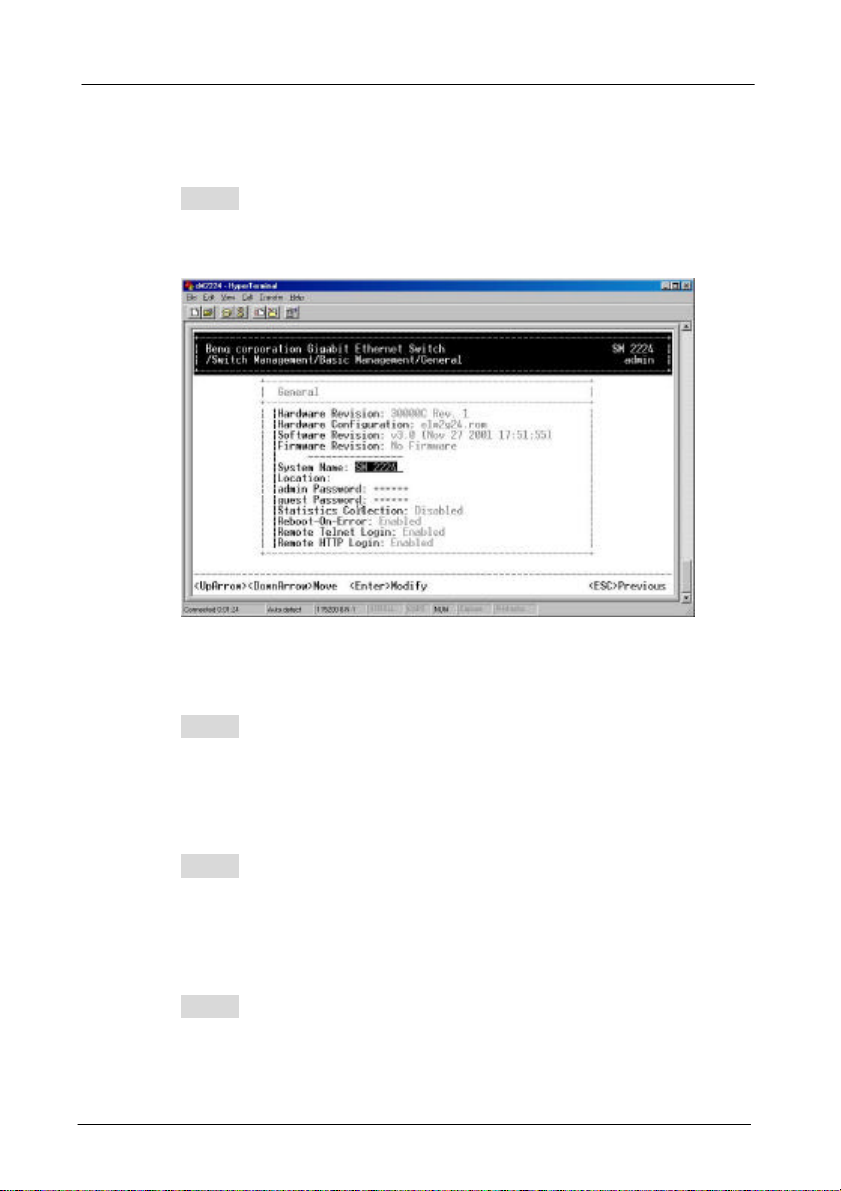
4.3.2 General Management Configurations
Step 1: Highlight [General] from [Basic Management] screen
and press <Enter>.
System Name
Step 2: System Name is highlighted. Press <Enter> if you
want to change it.
Location
Step 3: Move to highlight Location and press <Enter> if you
want to change it.
admin Password
Step 4: Move to highlight admin Password and press <Enter>
if you want to change it.
4. Menu-Driven Console Management -41
Page 46

guest Password
Step 5: Move to highlight guest Password and press <Enter>
if you want to change it.
Statistics Collection
Step 6: Move to highlight Statistics Collection and press
<Enter> if you want to change it, Disabled or Enabled.
Reboot-On-Error
Step 7: Move to highlight Reboot-On-Error and press <Enter>
if you want to change it, Disabled or Enabled.
Remote Telnet Login
Step 8: Move to highlight Remote Telnet Login and press
<Enter> if you want to change it, Disabled or Enabled.
Return to Basic Management
Step 9: Press <Esc> to return to [Basic Management] screen
when completed.
4. Menu-Driven Console Management -42
Page 47

4.3.3 LAN Port Configurations
Step 1: Highlight [LAN Port] from [Basic Management] screen
and press <Enter>.
SPEED & FLOW CONTROL
Step 2: Speed & Flow Control is highlighted. Press <Enter> if
you want to set speed or flow control on port.
4. Menu-Driven Console Management -43
Page 48

Step 3: Highlight All (10/100M or 1000M) Ports and press
<Enter> to configure at one time. Otherwise, move to
highlight each port and press <Enter> to configure
individually.
Step 4: Port Setting Options screen appears. Highlight
Speed & Flow Control and press <Enter>.
4. Menu-Driven Console Management -44
Page 49

Line Speed
Step 5: For Line Speed, move to highlight a desired setting
from Speed Options and press <Enter>.
<Note> In the Speed Options, Auto denotes auto negotiation
on speed and duplex mode, and FD denotes
full-duplex.
Step 6: Press <Esc> to previous screen. Highlight Flow
Control and press <Enter>
4. Menu-Driven Console Management -45
Page 50

Flow Control
Step 7: For Flow Control, move to highlight a desired setting
from the Flow Cntl Options and press <Enter>.
Step 8: Press <Esc> to a previous screen as shown in Step 3.
Admin. Control
Step 9: Highlight All Ports and press <Enter> to configure at
one time. Otherwise, move to highlight each port and
press <Enter> to configure individually.
4. Menu-Driven Console Management -46
Page 51

Step 10: For Admin Control, move to highlight Up or Down
from admin Status Options.
Step 11: E.g. Port 4 is set as Admin Down to stop TX/RX
transmission.
To allow TX/RX transmission on Port 4, move to
highlight Up from the options in Step 10.
4. Menu-Driven Console Management -47
Page 52

<Note> The other ports are set Admin Up but no link. (Down
denotes no link).
PHYSICAL PORT ADDRESS
Step 12: Press <Esc> to a previous screen as shown in Step 1.
Step 13: Move to highlight Physical Address to view physical
port address.
RETURN TO BASIC MANAGEMENT
Step 14: Press <Esc> to return to [Basic Management] screen
when completed.
4. Menu-Driven Console Management -48
Page 53

4.3.4 Console Port Configurations
Step 1: Move to highlight [Console Port] from [Basic
Management] screen.
Baud Rate
Step 2: Baud Rate is highlighted. Press <Enter> if you want to
change the current console baud rate.
Flow Control
Step 3: Move to highlight Flow Control and press <Enter> if
you want to change the current flow control method.
Modem Control
Step 4: Move to highlight Modem Control and press <Enter>
to decide a console modem connection, Disabled or
Enabled.
4. Menu-Driven Console Management -49
Page 54

Modem Setup String
Step 5: When a modem connection is enabled, move to
highlight Modem Setup String and press <Enter>.
Decide whether you want to use Default or Custom
Setup String.
<Note> Default Setup String configures the modem to auto
answer. It works for all Hayes compatible modems.
SLIP
Step 6: Move to highlight SLIP and press <Enter> if you want
to change it, Disabled or Enabled.
<Note> If you enable SLIP, a message tells you that the
console port becomes accessible only through the
SLIP protocol after you logout from the current console
screen.
SLIP Address
Step 7: Move to highlight SLIP Address and press <Enter> if
you want to set it.
SLIP Subnet Mask
Step 8: When SLIP IP address is entered, move to highlight
SLIP Subnet Mask and press <Enter>. Enter a
suitable subnet mask.
<Note> You must enter a SLIP address before you can enter a
SLIP subnet mask.
4. Menu-Driven Console Management -50
Page 55

RETURN TO BASIC MANAGEMENT
Step 9: Press <Esc> to return to [Basic Management] screen
when completed.
4.4 Advanced Management
Advanced management activities consist of L2 Switching
DataBase / IP Networking / Bridging / Static Filtering / Spanning
Tree / SNMP / Other Protocols / Port Trunking / Port Mirroring /
File Transfer.
4.4.1 Start with Selection Menu
Step 1: Highlight [Advanced Management] from [Switch
Management] screen and press <Enter>. The
[Advanced Management] screen appears:
4. Menu-Driven Console Management -51
Page 56

Step 2: Move to highlight a desired option and press <Enter>.
Or press <Esc> to exit.
L2 SWITCHING DATABASE
View and change VLAN, MAC address, IP multicast group, and
port perspectives.
IP NETWORKING
View and change IP settings, ARP and routing table parameters,
DHCP gateway settings, and ping settings.
BRIDGING
View and change the aging period for a MAC address and the
flood limit for all ports.
STATIC FILTERING
View / add / delete / search all source or destination MAC
addresses to be filtered.
SPANNING TREE
View and change spanning tree configurations, ports states,
path costs, and port priorities.
4. Menu-Driven Console Management -52
Page 57

SNMP
View and change the SNMP configuration.
OTHER PROTOCOLS
View and change GVRP and IGMP settings.
PORT TRUNKING
Assign a range of ports to trunking groups.
PORT MIRRORING
Mirror one port to Port 1 or Port 13.
FILE TRANSFER
Send files using the TFTP or Kermit protocol.
4. Menu-Driven Console Management -53
Page 58

4.4.2 L2 Switching DataBase
Highlight [L2 Switching DataBase] from [Advanced Management]
screen and press <Enter>.
VLAN Perspective
Step 1: The VLAN Perspective is highlighted. Press <Enter> to
view VLAN info of the default VLAN or if you want to
obtain a VLAN perspective instead of the default
VLAN.
<Note> Default VLAN:
The IEEE802.1Q standard defines VLAN ID #1 as the
default VLAN. The default VLAN includes all the ports
as the factory default. The default VLAN’s egress rule
restricts the ports to be all untagged, so it can, by
default, be easily used as a simple 802.1D bridging
domain. The default VLAN’s domain shrinks as
untagged ports are defined in other VLANs.
4. Menu-Driven Console Management -54
Page 59

The VLAN ID appears as both decimal and
hexadecimal values side by side in the VLAN
Perspective screen.
[+] to create VLAN: press [+] on keypad
[-] to delete VLAN: press [-] on keypad
Create VLAN
Step 2: Press [+] on keypad to enter New VLAN Settings.
Enter new VLAN ID and VLAN name.
Enter a new VLAN ID as either a
12-bit decimal or hexadecimal
value.
4. Menu-Driven Console Management -55
Page 60

<Note> “Remote” is appended to the VLAN ID automatically if
the VLAN is learned from a remote switch.
Add New Switch Ports
Step 3: Press <Esc> and appears the following screen. Press
[+] to add new switch ports to the newly created VLAN.
[+] to add switch ports: press [+] on keypad
[-] to delete switch ports: press [-] on keypad
* No precautionary message appears before you
delete a switch port.
* Be sure you want to delete it before doing so.
4. Menu-Driven Console Management -56
Page 61

Step 4: Move to highlight a suitable option from Port Options
and press <Enter>, e.g. Untagged Ports.
Step 5: From Select Untagged Ports, press <Enter> to select
All Ports or move to highlight each port individually
and press <Enter>. Similar procedure when you select
Tagged Ports and Forbidden Ports in Step 4
4. Menu-Driven Console Management -57
Page 62

<Note> If you added untagged ports and want to now add
tagged ports or forbidden ports, or vice versa, repeat
Step 4 and Step 5.
Step 6: Press <Esc> to a previous screen as shown in Step 1.
Delete VLAN
Step 7: Delete VLAN: highlight a VLAN ID and press [-] to
delete it.
Note that you cannot delete the default VLAN.
4. Menu-Driven Console Management -58
Page 63

Step 8: Press <Esc> to a previous screen as shown in Step 1
when completed with deleting a VLAN.
VLAN Info
Step 9: Highlight an existing VLAN and press <Enter> to view
VLAN information.
4. Menu-Driven Console Management -59
Page 64

Step 10: Move to highlight VLAN Activities and press <Enter>
to view or search activity information.
Step 11: Return to Step 9. Move to highlight VLAN Settings
and press <Enter>. The screen appears as shown in
Step 3 for adding or deleting switch ports.
IP MULTICAST GROUP PERSPECTIVE
Step 1: Move to highlight [IP Multicast Group Perspective] from
[L2 Switching DataBase] screen on page 54, and press
<Enter>.
Step 2: Move to highlight an address to view information
associated with this IP multicast group.
4. Menu-Driven Console Management -60
Page 65

MAC ADDRESS PERSPECTIVE
Step 1: Move to highlight [MAC Address Perspective] from [L2
Switching DataBase] screen on page 54, and press
<Enter>.
Step 2: Enter a MAC address to view characteristics
information, corresponding VLANs, and corresponding
ports in the switching database.
PORT PERSPECTIVE
Step 1: Move to highlight [Port Perspective] from [L2 Switching
DataBase] screen on page 54, and press <Enter>.
You can view VLAN activities and RMON statistics
here.
4. Menu-Driven Console Management -61
Page 66

Per Port VLAN Activities
Step 2: Per Port VLAN Activities is highlighted. Press
<Enter>.
Step 3: Move to highlight a port and press <Enter>.
E.g. select Port 18 to view corresponding VLAN
Activities.
4. Menu-Driven Console Management -62
Page 67

Step 4: View or search by MAC address individually.
Step 5: Press <Esc> to return to a previous screen as shown
in Step 1.
Per Port Statistics
Step 6: Move to highlight Per Port Statistics and press
<Enter>.
4. Menu-Driven Console Management -63
<Enter> to view by port
Page 68

Step 7: Move to highlight a port and press <Enter>.
E.g. select Port 1 to view corresponding VLAN
Activities.
Press <R> to reset counter for this port.
4. Menu-Driven Console Management -64
Page 69

Per Port MAC limit
Step 8: Move to highlight Per Port MAC Limit and press
<Enter>.
4. Menu-Driven Console Management -65
Page 70

Step 9: Move to highlight a port and press <Enter>.
E.g. select Port 1 to view corresponding MAC limit.
User can choose to set MAC learning function as 1.
limit with range: 0~16; or 2. Unlimited learning; or 3.
No MAC learning
4. Menu-Driven Console Management -66
Page 71
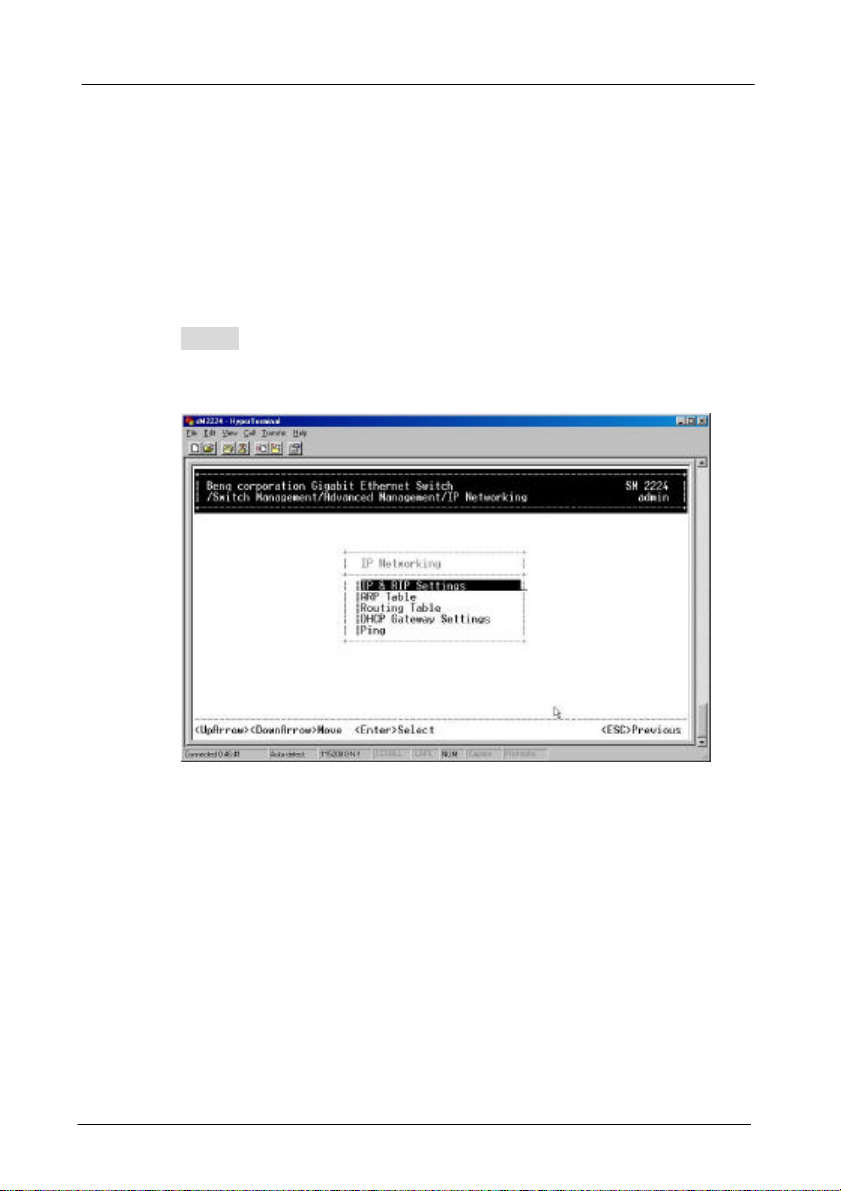
4.4.3 IP Networking
Move to highlight [IP Networking] from [Advanced Management]
screen and press <Enter>.
IP & RIP SETTINGS
Step 1: Highlight [IP & RIP Settings] from [IP Networking] and
press <Enter>.
4. Menu-Driven Console Management -67
Page 72

Step 2: The screen shows a list of VLAN IDs, IP addresses,
subnet masks, proxy ARPs, and RIPs currently
defined.
Before you can define a VLAN’s IP settings,
you must first create a VLAN as described in
previous section.
Step 3: Move to highlight the row that contains the parameters
you want to change, and then press <Enter>.
4. Menu-Driven Console Management -68
Page 73

Step 4: Move to highlight a parameter you want to change, and
then press <Enter> for modifications.
Otherwise, you may press <-> to delete that parameter.
Initial IP Settings
Step 5: Move to highlight IP Address and press <Enter>.
Step 6: Type an IP address and press <Enter>
Step 7: Press <Esc> until you return to [Switch Management]
screen.
Make sure you save the settings before you log out
4. Menu-Driven Console Management -69
Page 74

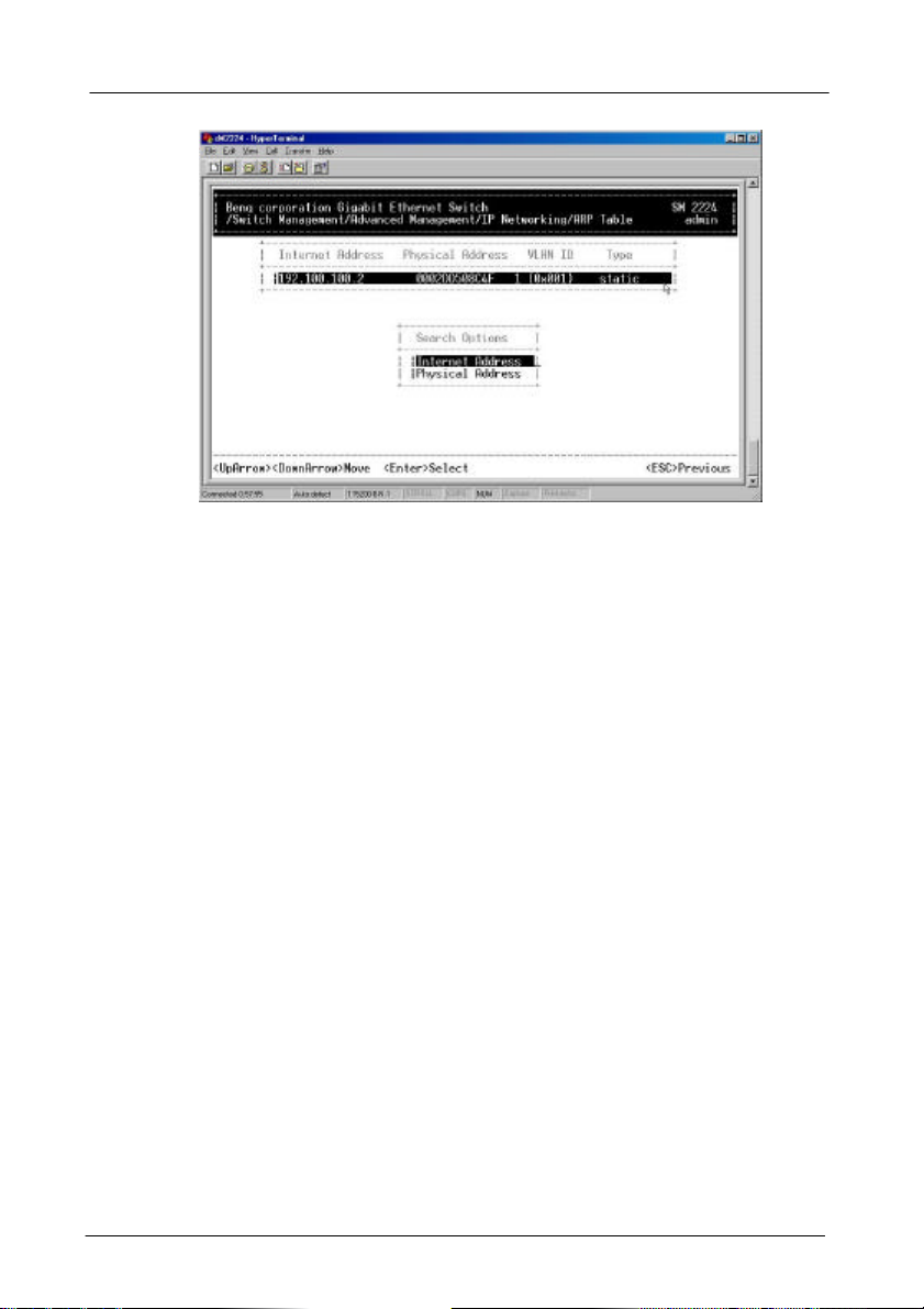
ARP TABLE SETTING
Step 1: Move to highlight [ARP Table] from [IP Networking] and
press <Enter>. The screen shows the ARP table
entries that have been defined or learned.
Add/Delete Static ARP Table Entries
Step 2: Press [+] on keypad to add an entry into the ARP
Table.
Enter Internet/Physical Addresses then.
4. Menu-Driven Console Management -70
Page 75

Step 3: Press [-] on keypad if you want to delete a static entry
from the ARP Table.
* No precautionary message appears before you delete an
entry from the ARP table.
* Be sure you want to delete it before doing so.
Search for ARP Table Entries
Step 4: Press <S> to search a static entry. You can search by
Internet address or physical address.
4. Menu-Driven Console Management -71
Page 76
4. Menu-Driven Console Management -72
Page 77

ROUTING TABLE
Step 1: Move to highlight [Routing Table] from [IP Networking]
and press <Enter>. The screen shows the Routing
Table allows you to view, add, delete or search a
particular routing path.
4. Menu-Driven Console Management -73
Page 78

The IP subnetwork address to which the switch can route
The related IP subnetwork mask to which the switch can
The number of hops needed between the switch and the
The IP route type for the IP subnetwork. There are six IP
A switch IP address on a specific IP
protocol other than one of the other four listed
ROUTING TABLE COLUMNS
Column Description
Network
Mask
Gateway
Metric
VLAN
Type
Protocol
packets.
route packets.
The IP address of the router at the next hop.
destination network.
The VLAN within which the gateway or destination resides.
route types:
Direct
Remote
Myself
Bcast
Mcast
Martian
Indicates one of the following:
Local
NetMgmt
ICMP
RIP
Other
A directly connected subnetwork.
A remote IP subnetwork or host address.
subnetwork.
A subnetwork broadcast address.
An IP multicast address.
An illegal IP address to be filtered.
A manually configured routing entry.
A routing entry set via SNMP.
A routing entry obtained via ICMP redirect.
A routing entry learned via the RIP protocol.
A
above.
4. Menu-Driven Console Management -74
Page 79

Add/Delete Routing Table Entries
Step 2: Press [+] on keypad to enter Route Options as shown
below.
Step 3: Press [-] to delete an entry in the routing table.
* No precautionary message appears before you delete
an entry from the routing table.
* Be sure you want to delete it before doing so.
Search for Routing Table Entries
Step 4: Press <S> to search a network address. Enter the
network address you want you are looking for.
4. Menu-Driven Console Management -75
Page 80

DHCP GATEWAY SETTINGS
Step 1: Move to highlight [DHCP Gateway Settings] from [IP
Networking] and press <Enter>.
Step 2: Move to highlight a row you want to change the DHCP
Gateway Settings, and press <Enter>
4. Menu-Driven Console Management -76
Page 81

Add/Delete Relay IP
Step 3: Press [+] on keypad to add a relay IP. Choose a
suitable interface or All Interfaces from Select
Outbound Relay Interfaces.
Otherwise, you may press [-] on keypad to delete a
relay IP.
* No precautionary message appears before you delete a
relay IP.
* Be sure you want to delete it before doing so.
DHCP Gateway Options
Step 4: Move to highlight DHCP Gateway and press <Enter>.
Decide to have it Disabled or Enabled.
4. Menu-Driven Console Management -77
Page 82

Maximum Hops
Step 5: Move to highlight Maximum Hops and press <Enter>
Step 6: Enter decimal number (1-16) to configure the
maximum number of hops.
Delay (sec)
Step 7: Move to highlight Delay (sec) and press <Enter>.
Step 8: Enter decimal number (0-65535) configure the delay in
seconds.
Preferred Server
Step 9: Move to highlight Preferred Server and press <Enter>.
Step 10: Enter IP address for the Preferred Server.
Step 11: To specify up to three more Preferred Servers, repeat
the above steps.
4. Menu-Driven Console Management -78
Page 83
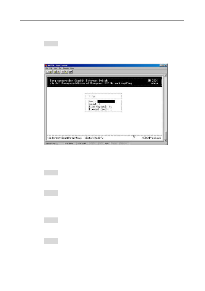
PING SETTINGS
Step 1: Move to highlight [Ping] from [IP Networking] and press
<Enter>.
Host
Step 2: Move to highlight Host and press <Enter>.
Step 3: Enter 4 decimal bytes (dot separated) as the IP
address to ping.
Count
Step 4: Move to highlight Count and press <Enter>.
Step 5: Specify a packet count number from 1 to 999, or type 0
for an infinite packet count. Press <Enter>.
4. Menu-Driven Console Management -79
Page 84

Size (bytes)
Step 6: Move to highlight Size and press <Enter>.
Step 7: Specify a packet size from 0-1500. Press <Enter>.
Timeout (sec)
Step 8: Move to highlight Timeout and press <Enter>.
Step 9: Specify a timeout value from 1-999. Press <Enter>.
Step 10: Press <Esc> to start to ping when completed with the
ping parameters.
4. Menu-Driven Console Management -80
Page 85

4.4.4 Bridging
Move to highlight [Bridging] from [Advanced Management]
screen, and press
<Enter>.
4. Menu-Driven Console Management -81
Page 86

AGING TIME
Step 1: Move to highlight Aging Time and press <Enter>.
Aging Options
Step 2: Set Aging Time is highlighted. Press <Enter>.
Enter a decimal number as bridge aging period in
seconds.
4. Menu-Driven Console Management -82
Page 87

Step 3: Otherwise, you may move to highlight No Aging, and
press <Enter>.
FLOOD LIMIT FOR ALL PORTS
Step 1: Move to highlight [Flood Limit for All ports] and press
<Enter>.
4. Menu-Driven Console Management -83
Page 88

Flooding Options
Step 2: Set Flood Limit is highlighted. Press <Enter>.
Enter a decimal number as flood limit in packets per
second.
Step 3: Otherwise, you may move to highlight Unlimited, and
press <Enter>.
4. Menu-Driven Console Management -84
Page 89

4.4.5 Static Filtering
Move to highlight [Static Filtering] from [Advanced Management]
screen, and press <Enter>.
4. Menu-Driven Console Management -85
Page 90

SOURCE/DESTINATION MAC ADDRESS OUT-FILTERS
Step 1: Move to highlight source MAC addresses or
destination MAC addresses for static filtering, and
press <Enter>.
If you select source MAC addresses, the SRC MAC
Out-Filter appears.
If you select destination MAC addresses, the DST
MAC Out-Filter appears
* No precautionary message appears before you delete a
specific MAC address from being filtered.
* Be sure you want to delete it before doing so.
4. Menu-Driven Console Management -86
Page 91

Add/Delete/Search
Step 2: Press [+] on keypad to add a specific MAC address to
be filtered.
Press [-] to delete a specific MAC address from being
filtered.
Press <S> to search through current list of MAC
addresses in the static filtering database. The static
filtering database maximum capacity is 64.
MAC ADDRESS IN-FILTERS
Step 1: Move to highlight MAC addresses In-Filters for static
filtering, and press <Enter>.
Step 2: Then move to highlight a port and press Enter to
change
4. Menu-Driven Console Management -87
Page 92

Add/Delete/Search
Step 3: Press [+] on keypad to add a specific MAC address to
be filtered.
Press [-] to delete a specific MAC address from being
filtered.
Press <S> to search through current list of MAC
addresses in the static filtering database. The static
filtering database maximum capacity is 64.
4.4.6 Spanning Tree Functions
Move to highlight [Spanning Tree] from [Advanced Management]
screen, and press <Enter>.
4. Menu-Driven Console Management -88
Page 93

User configurable
Down for
SPANNING TREE CONFIGURATIONS
Step 1: Move to highlight [Spanning Tree Configurations] if you
want to change Spanning Tree Protocol
Configurations.
Read-only values
Move
more
Spanning Tree Protocol
Step 2: Press <Enter> to enter Spanning Tree Options.
Decide to have it Disabled or Enabled.
Bridge Priority
Step 3: Move to highlight Bridge Priority and press <Enter>.
Type a decimal number for the bridge priority and
press <Enter>.
Hello Time (sec)
Step 4: Move to highlight Hello Time and press <Enter>.
Type a decimal number for the hello time and press
<Enter>.
4. Menu-Driven Console Management -89
Page 94

Max Age (sec)
Step 5: Move to highlight Max Age and press <Enter>.
Type a decimal number for the max age.
Forward Delay (sec)
Step 6: Move to highlight Forward Delay and press <Enter>.
Type a decimal number for the forward delay.
SPANNING TREE PORT STATES
Step 1: Move to highlight [Spanning Tree Port States] if you
want to change per port administration status, and
press <Enter>.
4. Menu-Driven Console Management -90
Page 95

Step 2: Move to highlight a port if you want to change its
administration status, and press <Enter>.
‘Disabled (Link Down)’ denotes Admin Status Up
without a link.
‘Forwarding’ denotes Admin Status Up with a link.
‘Admin Status Down’ denotes no TX/RX transmission
allowed
‘Admin Status Up’ denotes TX/RX transmission
allowed.
SPANNING TREE PATH COSTS
Step 1: To change the path cost, move to highlight [Spanning
Tree Path Costs] and press <Enter>.
4. Menu-Driven Console Management -91
Page 96

Step 2: Move to highlight All Ports or each port individually,
and press <Enter>. For new path cost, type a decimal
number and press <Enter>.
SPANNING TREE PORT PRIORITIES
Step 1: To change the priority level per port, move to highlight
[Spanning Tree Port Priorities] and press <Enter>.
Step 2: Move to highlight All Ports or each port individually,
and press <Enter>. For new priority value, type a
decimal number from 0-255, and press <Enter>. A low
value gives the port a greater likelihood of becoming a
Root port.
4. Menu-Driven Console Management -92
Page 97

Factory-default values
4.4.7 SNMP Functions
Move to highlight [SNMP] from [Advanced Management] screen,
and press <Enter>.
Move
Down for
more
SNMP Options
Step 1: Move to highlight SNMP and press <Enter>.
Decide to have it Disabled or Enabled.
Get Community Name
Step 2: Move to highlight Get Community Name and press
<Enter>.
Enter text and press <Enter>.
4. Menu-Driven Console Management -93
Page 98

Trap Community Name
Step 3: Move to highlight Trap Community Name 1 and press
<Enter>.
Enter text and press <Enter>.
Repeat to specify up to three more trap community
names.
Trap Host IP Address
Step 4: Move to highlight Trap Host 1 IP Address and press
<Enter>.
Type an IP address for trap host 1 and press <Enter>
Repeat to specify up to three more trap host IP
addresses
Cold Start Trap
Step 5: Move to highlight Cold Start Trap and press <Enter>.
Decide to have it Disabled or Enabled.
Warm Start Trap
Step 6: Move to highlight Warm Start Trap and press <Enter>.
Decide to have it Disabled or Enabled.
Link Down Trap
Step 7: Move to highlight Link Down Trap and press <Enter>.
Decide to have it Disabled or Enabled.
Link Up Trap
Step 8: Move to highlight Link Up Trap and press <Enter>.
Decide to have it Disabled or Enabled.
4. Menu-Driven Console Management -94
Page 99

Authentication Failure Trap
Step 9: Move to highlight Authentication Failure Trap and
press <Enter>.
Decide to have it Disabled or Enabled.
Rising Alarm Trap
Step 10: Move to highlight Rising Alarm Trap and press
<Enter>.
Decide to have it Disabled or Enabled.
Falling Alarm Trap
Step 11: Move to highlight Falling Alarm Trap and press
<Enter>.
Decide to have it Disabled or Enabled.
Topology Change Trap
Step 12: Move to highlight Topology Change Trap and press
<Enter>.
Decide to have it Disabled or Enabled.
4. Menu-Driven Console Management -95
Page 100

4.4.8 Other Protocols
Move to highlight [Other Protocols] from [Advanced
Management] screen, and press <Enter>.
4. Menu-Driven Console Management -96
 Loading...