

Page 1
BenQ FP93GW Service Manual
FP93GS
9
9
Product Service Manual – Level 2
Service Manual for BenQ:
FP93GW
P/N: 9H.0A9LN.Ixx
Applicable for All Regions
Version: 002
Date:07/04/09
Notice:
- For RO to input specific “Legal Requirement” in specific NS regarding to responsibility
and liability statements.
- Please check BenQ’s eSupport web site, http://esupport.benq.com, to ensure that you
have the most recent version of this manual.
First Edition (June, 2006)
© Copyright BenQ Corporation 2006. All Right Reserved.
1
Page 2

BenQ FP93GW Service Manual
/ FP93GS
Content Index
1. Precautions & Safety Notices
1.Safety Precaution
2. Produce Safety Notice
3.Service Notes
2.Product Overview
2.1. Specification
2.2Signal interface
2.3 Video performance
2.4 Scan range
2.5 Plug & Play DDC2B DDC-CI Support
2.6 Support Timings
2.7 Operational &Function Specification
2.7.1 Video performance
2.7.2Brightness Adjustable Range
2.7.3 Acoustical Noise
2.7.4 Environment
2.7.5 Transportation
2.7.7 Electrostatic Discharge Requirements
2.7.8 EMC
2.7.9 Reliability
2.8 LCD Characteristics
2.8.1 The Physical definition & Technology summary of LCD panel
2.8.2 Optical characteristics of LCD panel
2.9 User Controls
2.9.1 User’s hardware control definition
2.9.2OSD control function definition
2.10 Mechanical Characteristics
2.10.1 Dimension
2.10.2 Weight
2.10.3 Plastic
2.10.4Carton
2.11 Pallet & Shipment
2.11.1 Container Specification
2.11.2 Carton Specification Product: Package:
3. Exploded View
3.1 Disassembly /Assembly
2
Page 3

BenQ FP93GW Service Manual
4. Level 1 Cosmetic / Appearance / Alignment Service
4.1 Software / Firmware Upgrade Process
4.2. Alignment procedure (for function adjustment)
4.2.1. Command definition
5. Level 2 Circuit Board and Standard Parts Replacement
5.1. Block diagram
5.1.1 Circuit operation theory
5.2. TROUBLE SHOOTING GUIDE
5.3. Spare Parts List
Appendix 1 – Screw List / Torque
3
Page 4

BenQ FP93GW Service Manual
PRECAUTIONS
This monitor is manufactured and tested on a ground principle that a user’s safety comes
first. However, improper used or installation may cause damage to the monitor as well as to
the user.
WARNINGS:
z This monitor should be operated only at the correct power sources indicated on the label
on the rear of the monitor. If you’re unsure of the power supply in you residence, consult
your local dealer or Power Company.
z Do not try to repair the monitor by yourself, as it contains no user-serviceable parts. This
monitor should only be repaired by a qualified technician.
z Do not remove the monitor cabinet. There is high-voltage parts inside that may cause
electric shock to human bodies.
z Stop using the monitor if the cabinet is damaged. Have it checked by a service technician.
z Put your monitor only in a lean, cool, dry environment. If it gets wet, unplug the power
cable immediately and consult your closed dealer.
z Always unplug the monitor before cleaning it. Clean the cabinet with a clean, dry cloth.
Apply non-ammonia based cleaner onto the cloth, not directly onto the class screen.
z Do not place heavy objects on the monitor or power cord.
2. PRODUCT SAFETY NOTICE
Many electrical and mechanical parts in this chassis have special safety visual
inspections and the protection afforded by them cannot necessarily be obtained by using
replacement components rated for higher voltage, wattage, etc. Before replacing any of
these components read the parts list in this manual carefully. The use of substitute
replacement parts, which do not have the same safety characteristics as specified in the
parts list, may create shock, fire, or other hazards.
3. SERVICE NOTES
z When replacing parts or circuit boards, clamp the lead wires around terminals before
soldering.
z Keep wires away from high voltage, high temperature components and sharp edges.
z Keep wires in their original position so as to reduce interference.
z Adjustment of this product please refers to the user’ manual.
4
Page 5
BenQ FP93GW Service Manual
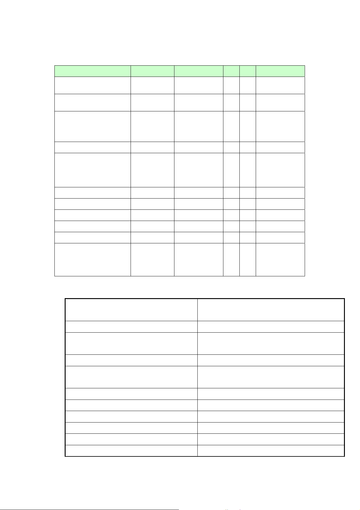
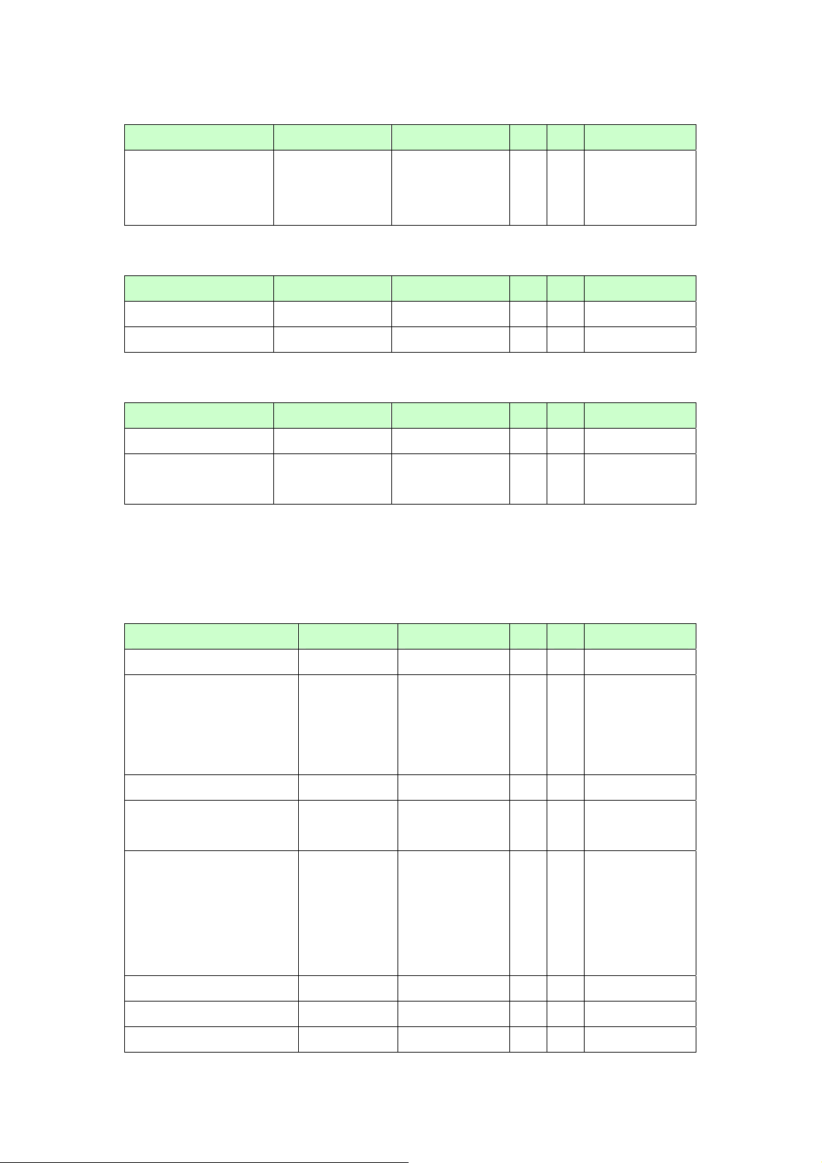
2.Product Overview
2.1 Power supply
Item condition Spec OK NA Remark
Input Voltage range
Input Current range
Power consumption
DMPS <2W
In rush Current
Earth Leakage Current
Hi-pot
Power Line Transient
CCFL Operation range
Power cord
Universal input
full range
100Vac
240Vac
with Audio,
normal “on”
operation
100Vac,cold
star,25°C;
240Vac,cold
star,25°C
100~240VAC
1.2A (max.)
0.6A (max.)
<45W
40A (max)
60A(max)
√
√
LED: Green
√
LED: Amber
√
√
√
To be determined
by the business
country.
2.2 Signal interface
Input Connector Analog : D-sub 15
Digital: DVI-D
Default Input Connector Defaults to the first detected input
Equal to twice the weight of the monitor for five
Video Cable Strain Relief
minutes
Video Cable Connector DB-15 Pin out Compliant DDC 2B / CI
1. Video RGB (Analog): Separate
Video Signals
2. DVI (Digital)
Video Impedance 75 Ohms (Analog), 100 Ohms (Digital)
Maximum PC Video Signal 950 mV with no damage to monitor
Maximum Mac Video Signal 1250 mV with no damage to monitor
Sync Signals TTL
DDC 1/2B Compliant with Revision 1.3
Sync Compatibility Separate Sync
5
Page 6
BenQ FP93GW Service Manual
Video Compatibility
Shall be compatible with all PC type computers,
Macintosh computers, and after market video cards
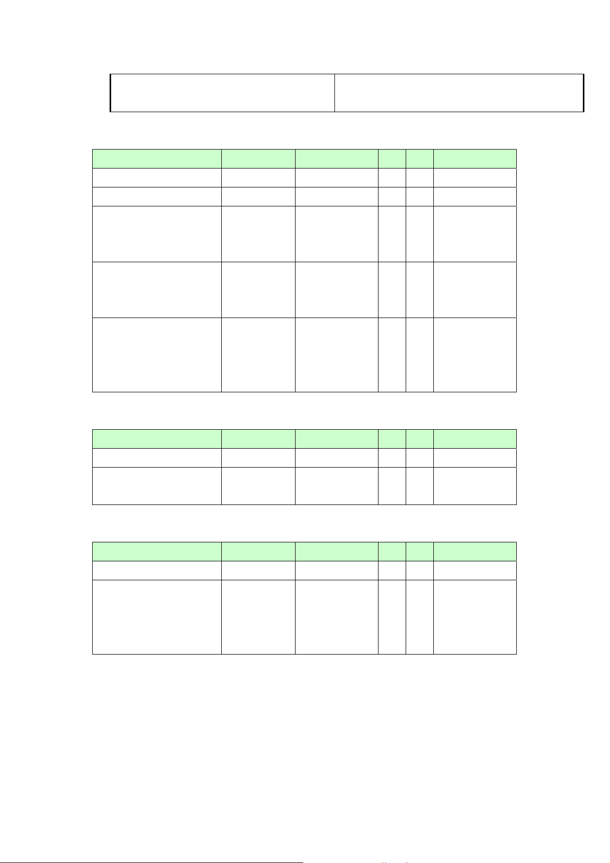
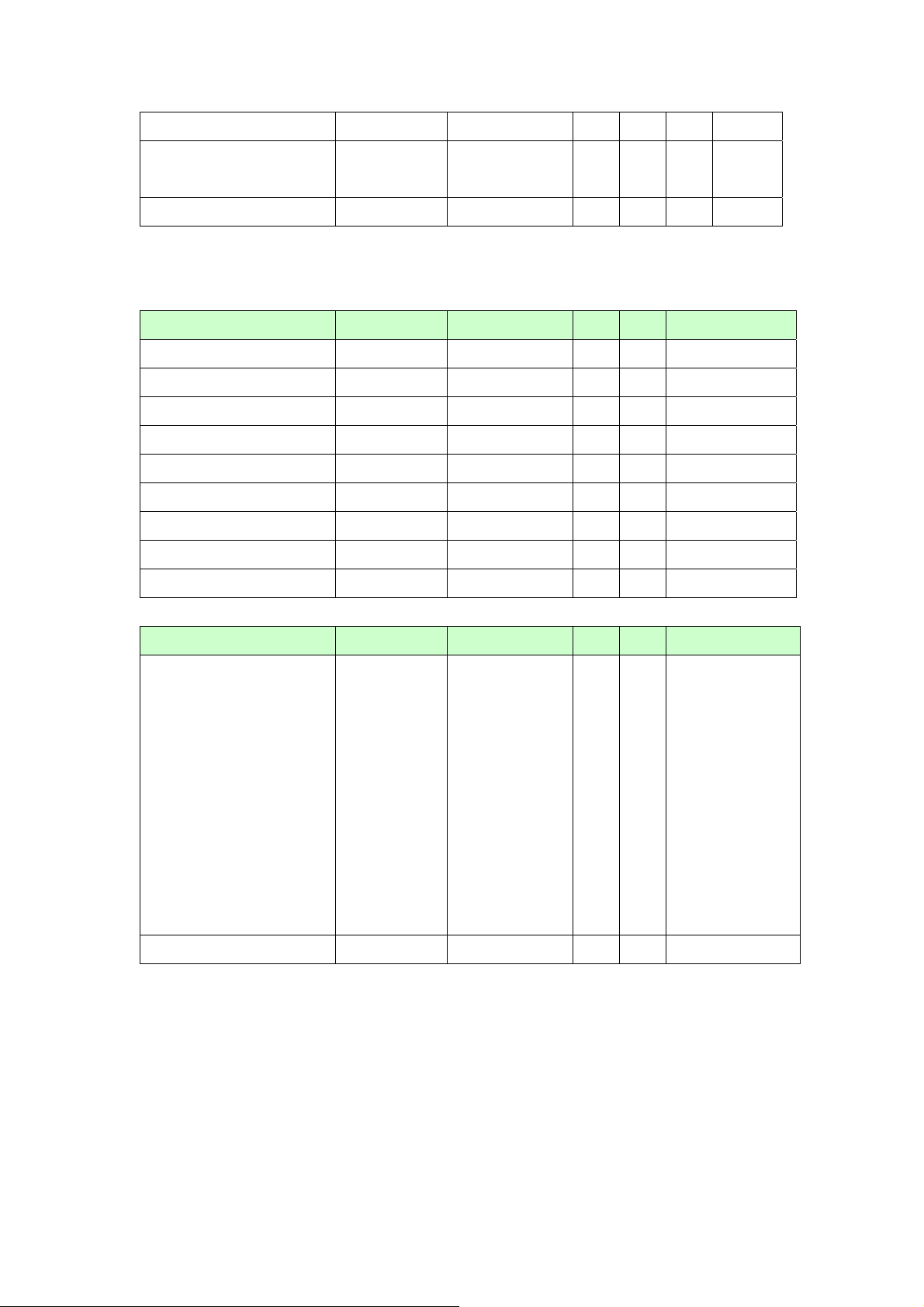
2.3 Video Performance
Item condition Spec OK NA Remark
Max. support Pixel rate 135MHz
Max. Resolution 1440x900
Rise time+Fall time <25% of
minimum pixel
clock period
Setting Time after
overshoot/undershoot
Overshot/undershoot
<5% final
full-scale value
<12% of step
function voltage
level over the full
√
√
Refer to VESA
√
Refer to VESA
√
Refer to VESA
√
VSIS Standard
V1R2
VSIS Standard
V1R2
VSIS Standard
V1R2
voltage range
2.4 Scan range
Item condition Spec OK NA Remark
Horizontal
Vertical
31 ~ 82 KHz.
56~76Hz
√
√
Without frame
buffer.
2.5 Plug & Play DDC2B DDC-CI Support
Item condition Spec OK NA Remark
DDC channel type DDC2B
EDID
Version #1,
Revision #3.
√
√
VESA’s EDID
Standard
Version #3,
Revision #0,
6
Page 7

BenQ FP93GW Service Manual
)
V-sy
)
V
2.6 Support Timings
Horizontal Scan Range: 31-82 KHz Vertical Refresh Rate: 56-76 Hz
Resolution Pixel clock (Mhz)H-sync (Khz
640x350 25.18 31.47 70.09 P N
30.24 35.00 66.67 N N
640x480
640x480 31.50 37.50 75.00 N N
720x400 28.32 31.47 70.08 N P
832x624 57.27 49.71 74.53 N N
800x600
848x480
720x576 32.71 35.83 60.00 N N
1024x768
1152x864
1152x870 100.00 68.68 75.06 N N
1152x900
1280x720
1280x768-R 68.25 47.40 60.00 P N
1280x768
1280x800 83.50 61.648 59.81 P N
1280x960 108.00 60.00 60.00 P P
1280x1024
1280x1024
1360x768 85.50 47.71 60.01 P P
1440x900-R 88.75 55.496 59.901 P N
1440x900 106.5 55.935 59.887 N P
1440x900 136.48 70.50 75.00 N P
25.17 31.47 59.94 N N
31.50 37.86 72.81 N N
36.00 35.16 56.25 P P
40.00 37.88 60.32 P P
50.00 48.08 72.19 P P
49.50 46.88 75.00 P P
33.75 31.02 60.00 P P
31.50 29.83 59.66 N P
37.52 35.00 70.00 N P
39.25 36.07 72.00 N P
41.00 37.68 74.77 N P
65.00 48.36 60.00 N N
75.00 56.48 70.07 N N
78.43 57.67 72.00 N P
80.00 60.24 74.93 N N
78.75 60.02 75.03 P P
94.50 63.85 70.01 P P
108.00 67.50 75.00 P P
92.94 61.80 65.95 N N
105.59 71.73 76.07 N N
74.25 45.00 59.94 N P
74.50 44.77 59.86 N P
95.75 56.46 74.78 N P
79.50 47.78 59.87 N P
102.25 60.29 74.89 N P
108.00 63.98 60.02 P P
126.99 74.88 69.85 P P
124.90 74.40 70.00 N N
134.60 77.90 72.00 P P
135.00 79.98 75.02 P P
135.09 81.18 76.16 N N
nc (Hz
H-Pol
-Pol
7
Page 8

BenQ FP93GW Service Manual
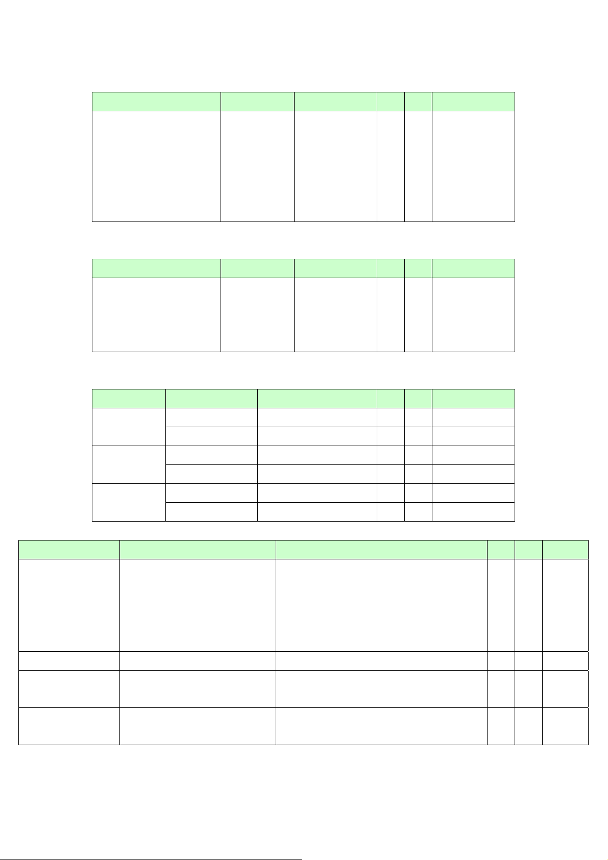
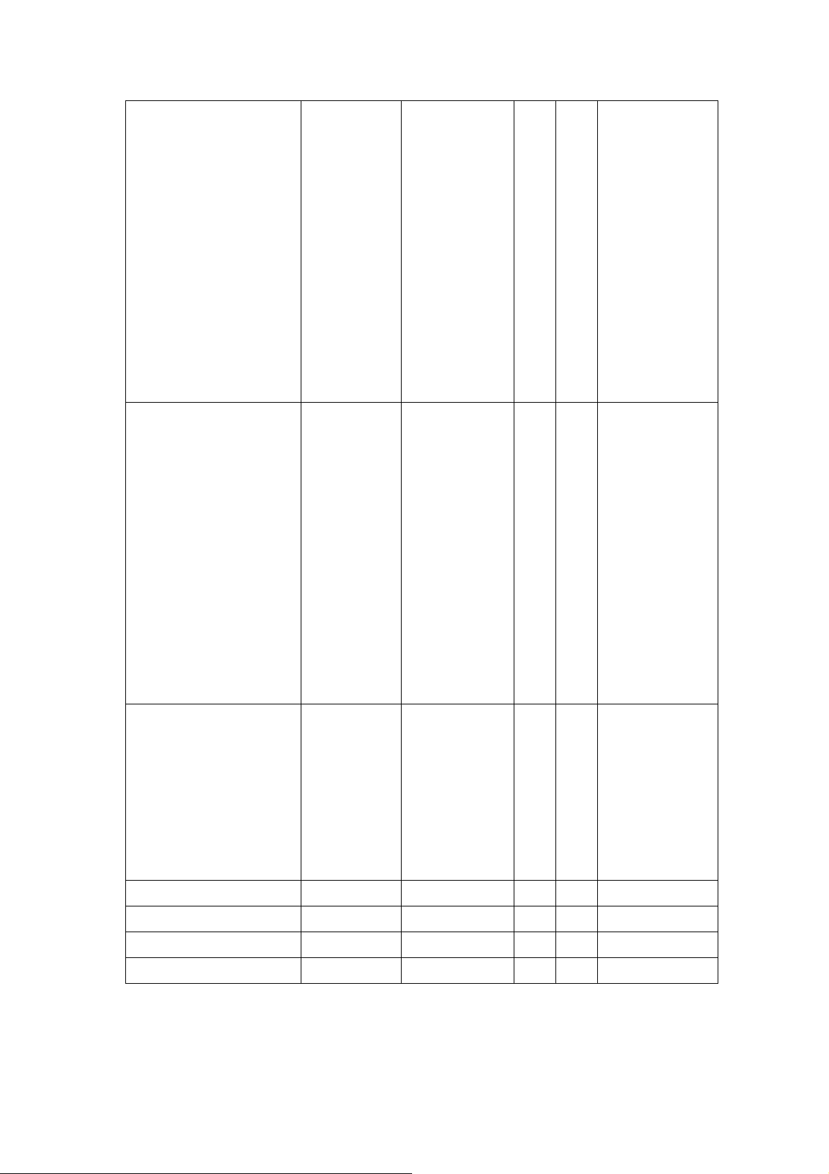
2.7 Operational &Function Specification
2.7.1 Video Performance
* All Spec. of monitor need to warm up at lease 1hr
Item condition Spec OK NA Remark
Resolution Any input
resolution
modes which
are list in the
timing table
(under
1440x900).
Contrast ratio
Max. resolution
1440x900
For INL
Min: 500:1
Typical: 700:1
For CMO
Min: 500:1
Typical: 850:1
Brightness Contrast and
brightness
max. value
230cd/m2
(Min.),
300cd/m2
(Typical)
√
√
√
Response time
Viewing angle
5 ms (Typical),
15ms (Max.)
Hor: 160°,
√
√
Ver: 160°
(Typical,
CIE coordinate of white
CR>10)
x--0.313 ±
√
0.030;
y--0.329 ±
0.030
Display colors
16.2M
√
(6-bits+FRC)
Response time with AMA
8
Page 9
BenQ FP93GW Service Manual
2.7.2 Brightness Adjustable Range
Item condition Spec OK NA Remark
Brightness adjustable range At default
contrast level
(saturate
point)&
Full-white color
pattern
2.7.3 Acoustical Noise
Item condition Spec OK NA Remark
Acoustical Noise At 1 meter
distance&
audio function
disable
2.7.4 Environment
Item condition Spec OK NA Remark
≧100 cd/m2
(Setting
brightness max.
value 100%; Min.
brightness value)
≦40dB/A
√
√
Temperature
Humidity
Altitude
2.7.5 Transportation
Item condition S pec OK NA Remark
Vibration
Unpackage vibration
Drop
Package, Non-operating Random Vibration:1. Sweep Frequency:
Unpackage , Non-operating
Package, Non-operating
Operating 0°C to 40°C
Non-operating -20°C to 60°C
Operating 20% to 80%
Non-operating 10% to 80%
Operating 0 to 3048 M (10000 ft)
Non-operating 0 to 12192M (40000 ft)
5~200Hz 2. Amplitude 1.47Grms 3.
Duration Time: 20 minute each axis( total
60 ) 4. Direction: 3 mutually perpendicular
axis (x, y, z)
91cm Height(1 corner,3 edges,6
√
√
√
√
√
√
√
√
√
faces)
shock
Wooden package ,
Non-operating
√
9
Page 10
BenQ FP93GW Service Manual
2.7.6 Electrostatic discharge Requirements
Item condition Spec OK NA Remark
Electrostatic discharge
InnoLux SPEC
Contact: 4KV
Air: 8KV
√
D-sub & DVI
cable pin only
need test 4KV
2.7.7 EMC
Item condition Spec OK NA Remark
TCO03
EMI
2.7.8 Reliability
Item condition Spec OK NA Remark
MTBF Prediction
CCFL life time
95% Confidence
Luminance
becomes 50%
≧ 60,000 Hours
≧ 40,000 Hours
at 6.8mA (min)
√
See note1.
√
Note1. Display an all white field at mid Brightness and Contrast settings.
2.8. LCD Characteristics
2.8.1 The physical definition &technology summary of LCD panel
Item condition Spec OK NA Remark
LCD panel supplier INL&CMO
Panel type of supplier INL
MT190AW01 V.2;
CMO
M190A1- L02
Screen diagonal 19 inch diagonal
Display area 410.4mm (H)
x256.5mm (V)
Physical size
427.2mm
√
√
√
√
√
(W)x277.4mm
(H)x17mm(D)
(Typ.)
Weight 2500g (max.)
Technology TN type √
Pixel pitch
0.285mm x
10
√
v Per one triad.
Page 11

BenQ FP93GW Service Manual
0.285 mm
Pixel arrangement R/G/B vertical
strip
Display mode Normal white
Support color 16.2M colors (6
bits with FRC)
√
√
√
2.8.2 Optical characteristics of LCD panel
Item unit Conditions min Typ. max remark
Viewing angle
Contrast ratio Normal Direction 500 700
[degree]
[degree]
Horizontal
(Right/Left) CR ≥
10
Vertical
(Up/Down) CR ≥
10
70/
70
70/
70
80/
80 - -
80/
80 - -
Response time
Color/chromaticity
[msec] Rising Time - 1.5 6.5
[msec] Falling Time - 3.5 8.5
[msec] Rising + Falling - 5 15
Red x 0.610 0.640 0.67
0
Red y 0.304 0.334 0.36
4
Green x 0.256 0.286 0.31
6
Green y 0.569 0.599 0.62
9
Blue x 0.124 0.154 0.18
4
Blue y 0.047 0.077 0.10
7
White x 0.283 0.313 0.34
White y 0.299 0.329 0.35
Luminance uniformity
[%] 9 points 75 80 -
3
9
11
Page 12
BenQ FP93GW Service Manual
measurement % %
White Luminance @CCFL
[cd/m2] 220 300 -
7.0mA (center)
Crosstalk
2.9User Controls
2.9.1 User’s hardware control definition
Item condition Spec OK NA Remark
Monitor power button
Enter button
Right/Inc.button
Left/Dec. button
I-key button
Mode selection button
Input Select key
Mute button
Input source select button
√
√
√
√
√
√
√
√
√
2.9.2 OSD control function definition
Item condition Spec OK NA Remark
Monitor power button
Enter button
a. Turn on the
monitor.
b. Activate the OSD
control menu.
c. Select the
specific function.
d. Turn off the
monitor by pressing
the button for
3seconds.
√
√
12
Page 13
BenQ FP93GW Service Manual
Right/Inc.button
Left/Dec. button
a. Activate the
Volume control
menu, and increase
the value (optional)
b. View the
previous function in
the main OSD
menu
c. Increase the
value of specific
function which has
been selected
a. Activate the
Volume control
menu, and
decrease the value
(optional)
√
√
I-key button
Mode selection button
Input Select key
b. View the next
function in the main
OSD menu
c. Decrease the
value of the specific
function which has
been selected
Up + Down
Activate the Auto
Adjustment function
to optimize the
picture
performance
automatically
√
Auto adjustment
√
√
Mute button
Input source select button
2.10 Mechanical characteristics
2.10.1Dimension
13
√
√
Page 14

BenQ FP93GW Service Manual
Item condition Spec OK NA Remark
Bezel opening
Monitor without stand
Monitor with stand
Carton Box(outside)
Tilt and Swivel range
2.10.2 Weight
Item condition Spec OKNA Remark
Monitor (Net)
Monitor with packing(Gorss)
2.10.3 Plastic
Item condition Spec OK NA Remark
Flammability
Heat defelection to
UV stability
411.6x 257.7mm
L×W×Hmm
L×W×Hmm
L×W×Hmm
435.6*285.7*63.0mm
435.6*366.3*174.4mm
514*156*422mm
Tilt:-4~20degree
Swivel:
0 degree
4.25±0.3 Kg
5.50±0.3 Kg
√
√
94-HB
ABS 80°C
ABS
Delta E<12
√
√
√
√
√
√
√
√
resin
Texture
Color
2.10.4 Carton
Item condition Spec OK NA Remark
Color
Material
Compression strength
Burst strrngth
Stacked quantity
2.11. Pallet &Shipment
2.11.1 Container Specification
ABS
MT11000&MT11010&
MT11020
BCS-7015A(BLACK)/
BCS-8110C
Kraft
C Flute
180 KGF
16 KGF/cm2
5 Layers
√
√
√
√
√
√
√
√
LENS: MT11000
BACK COVER&Logo
cover: MT11020
Others:MT11010
Bezel painting
Stowing
Type
Containter Quatity of
Produces
(sets)
(Every
14
Quatity of
Produces
(sets)
(Every Pallet)
Quatity of
Pallet (sets)
(Every
container)
Page 15

BenQ FP93GW Service Manual
container)
With Pallet
20’ 800 Pallet A:80 Pallet A:10
40’ 1600 Pallet A:80 Pallet A:20
Without
Pallet
20’
40’
N/A N/A N/A
N/A N/A N/A
2.11.2 Carton Specifition
Product:
Net Weight (Kg) Gross Weight(Kg) Dimension w/o Base
LxWxH (mm)
4.25±0.3 Kg
Package:
Carton Interior Dimension (mm)
LxWxH
5.5±0.3 Kg
435.6*285.7*63.0mm 435.6*366.3*174.4mm
Carton External Dimension (mm)
LxWxH
Dimension w/ Base
LxWxH (mm)
506*148*405mm
514*156*422mm
15
Page 16

BenQ FP93GW Service Manual
3. Disassembly & Assembly
3.1 Exploded Diagram
714080250000R A SSY,PANEL(B),W/O SPK,LE1965-512
16
Page 17

BenQ FP93GW Service Manual
ASSEMBLY BLOCK
NOTES: The screw marked by purple color is the fix screw for two adjacent block
17
Page 18

BenQ FP93GW Service Manual
18
Page 19

BenQ FP93GW Service Manual
19
Page 20

BenQ FP93GW Service Manual
20
Page 21

BenQ FP93GW Service Manual
DISASSEMBLY BLOCK
NOTES: The screw marked by purple color is the fix screw for two adjacent
block
21
Page 22

BenQ FP93GW Service Manual
22
Page 23

BenQ FP93GW Service Manual
23
Page 24

BenQ FP93GW Service Manual
24
Page 25

BenQ FP93GW Service Manual
4Level 1 Cosmetic / Appearance / Alignment Service
4.1 Software / Firmware Upgrade Process
Upload firmware to MCU via VGA Cable
1. Connect ISP board between monitor and PC as below configuration
.
Insert to Parallel
Port on PC
ISP Board
Parallel
D-SUB
2. Press the “connect” button in ISP.exe, and select the device type, which is used in this
monitor. Choose the corresponding firmware version, and load to MCU.
3. After finish, please plug out power cable and re-start monitor again.
LCD Monitor
D-Sub
4.2 Alignment procedure (for function adjustment)
4.2.1.1 Preparation:
1. Setup input timing VESA to 1440*900@75Hz,32-Grays pattern.
2. Setup units and keep it warm up for at least 30 minutes.
4.2.1.2 timing adjustment
1. Enter to factory mode setting area (by pressing "minus"+ "power" at the same time during
power off).
2. Check the settings to following values:
contrast =50;
brightness=100;
color enhancement=general;
3. Then turn off the monitor power.
4.2.3 Function key Definitions
4.2.3.1 Control buttons on the Back bezel
• 3 buttons at the rear side of monitor
•
“UP”
Activate the Volume control menu, and increase the value
25
Page 26

BenQ FP93GW Service Manual
(optional)
View the previous function in the main OSD menu
Increase the value of specific function which has been
selected
•
“MENU/POWER”
Turn on the monitor
Activate the OSD control menu
Select the specific function
Turn off the monitor by pressing the button for 3 seconds
“DOWN”
•
Activate the Volume control menu, and decrease the value
(optional)
View the next function in the main OSD menu
Decrease the value of the specific function which has been
selected
•
“UP” and “DOWN”
Activate the Auto Adjustment function to optimize the picture
performance automatically
4.2.3.2 Hot Key Operation
CONTROL KEY KEYS FUNCTION
A. When OSD displays, press [MENU] to return to previous level menu
[MENU]
[Enter]
[►], [◄]
[POWER] Power on or power off the monitor
B. When OSD isn’t shown on screen, press [MENU] to enter OSD interface
C. press [Enter] to enter Service Page When OSD isn’t shown on screen in Service
Page Mode
A. When OSD isn’t shown on screen, press [Enter] to Select Input Source
B. When OSD displays, press [Enter] to perform function of menu icon that is highlight
or enter next level menu
A. When “MENU OSD” displays, press these keys to change the contents of an
adjustment item, or change an adjustment value
B. When “MENU OSD” un-displays, press [◄],to show Brightness/Contrast Menu
press [►] to Show Picture Mode Menu.
[iKey] press [iKey] to perform auto-adjustment
4.2.3.3OSD Control
The On-Screen Display (OSD) shall be an easy to use icon based
menu through keypad OSD buttons or remote control unit. The unit
shall leave the factory with all OSD controls set to their default values.
26
Page 27

BenQ FP93GW Service Manual
Main Menu, Analog Input
Level 1 Level 2 Level 3 Default
EXIT
AUTO
ADJUSTMENT
CONTRAST 50
BRIGHTNESS 100
INPUT SIGNAL
SELECT
OSD MENU
LANGUAGE
EXIT
ANALOG (D-SUB)
DIGITAL (DVI)
EXIT
ENGLISH
GERMAN
FRENCH
ITALIAN
SPANISH
ANALOG (D-SUB)
ENGLISH
ASPECT RATIO
COLOR
SIMPLIFIED CHINESE
TRADITIONAL CHINESE
JAPANESE
RUSSIAN
SWEDISH
POLISH
DUTCH
Serbo-Croatian
Czech
Hungarian
Portuguese
Romanian
EXIT
NATIVE
FULL SCREEN
EXIT
NATIVE
GENERAL
ENHANCEMENT
POWER SAVING EXIT STANDARD
GENERAL
TEXT
PICTURE
27
Page 28

BenQ FP93GW Service Manual
MODE
OTHERS
STANDARD
ADVANCED
EXIT
AUTO COLOR
DDC/CI
COLOR TEMPERATURE
OSD MENU POSITION
EXIT
ON
OFF
EXIT USER
USER/RED 80
USER/GREEN 80
USER/BLUE 80
COOL
WARM
EXIT
RIGHT
CENTER
ON
RIGHT
LEFT
CLOCK 50
PHASE By Timing
HORIZONTAL POSITION 50
VERTICAL POSITION 50
INFORMATION BY TIMING
RECALL
Main Menu, Digital Input
Level 1 Level 2 Level 3 Default
EXIT
CONTRAST 50
BRIGHTNESS 100
INPUT SIGNAL
SELECT
EXIT
ANALOG (D-SUB)
DIGITAL (DVI)
ANALOG (D-SUB)
OSD MENU
LANGUAGE
EXIT
ENGLISH
GERMAN
FRENCH
ITALIAN
28
ENGLISH
Page 29

BenQ FP93GW Service Manual
ASPECT RATIO
SPANISH
SIMPLIFIED CHINESE
TRADITIONAL CHINESE
JAPANESE
RUSSIAN
SWEDISH
POLISH
DUTCH
Serbo-Croatian
Czech
Hungarian
Portuguese
Romanian
EXIT
NATIVE
FULL SCREEN
NATIVE
COLOR
ENHANCEMENT
POWER SAVING
MODE
OTHERS
EXIT
GENERAL
TEXT
PICTURE
EXIT
STANDARD
ADVANCED
EXIT
DDC/CI
COLOR TEMPERATURE
EXIT
ON
OFF
EXIT USER
USER/RED 80
USER/GREEN 80
USER/BLUE 80
COOL
GENERAL
STANDARD
ON
OSD MENU POSITION
29
WARM
EXIT
RIGHT
CENTER
LEFT
RIGHT
Page 30

BenQ FP93GW Service Manual
INFORMATION BY TIMING
RECALL
• Volume Menu
Level 1 Default
VOLUME 50%
4.2.3.4. Factory Mode Introduction
When signal is input, press “power key” to turn off the monitor. Press “-” and “Power” together
to turn on the monitor. After power on, press “Power” to call out Main Menu, then press “-“for
select the “F” item, then press “power/menu”, you can go into Factory mode.
EXIT: Escape from Factory menu.
PANEL: Display panel information.
AUTO COLOR: Automatically calibrate chip ADC parameter by using chip internal DAC.
GAIN: ADC gain value
OFFSET: ADC offset value
SPAN and STEP: Spread spectrum value.
BRI: Brightness value
CON: Contrast value
9300K: Set color temperature 9300K
6500K: Set color temperature 6500K
USER: Set user preferred color temperature
RS232: F/W RS232 debug on or off
BANK, ADDR, VALUE, H-TOTAL:F/W adjust the scaler register and h-total to panel for better
performance.
TIME: The time of backlight used.
4.2.3.5 After repair, to ensure the quality you should do the following test and
adjustment
Item Content Equipment
Tes t O SD
function
1.Signal is set as 1440×900@60Hz under General-1
2.Checking whether each single function key and
compound function key can be worked.
Chroma
Signal Generator
30
Page 31

BenQ FP93GW Service Manual
g
g
Contrast
Check
Color
Temperatur
e
Modes
switching
check
1. Set input mode to 1440×900@60Hz
2. Set Pattern to 32 gray shades
3. Set contrast to the max. The brightest 5~8 shades
brightness
cannot be distinguished.
1. Do “Auto color Balance” at 1440×900@60Hz, 32gray
shades
2. Measure color temperature, check it complies with the
following temperature :
6500K x = 0.313 +/- 0.03, y = 0.329+/-0.03
1. Use Chroma Pattern Generator to make sequence.
VESA (640x480 800x600 1024x768 1280x1024),
and power saving signal,etc.
2. Confirm the above timing modes must be full screen
Chroma
Signal Generator
Chroma Signal
Generator and color
analyzer
Chroma
Signal Generator
VGA cable
detector
Panel
Flicker
Power
saving
and
When VGA cable is not plugged, the monitor will work in
power saving mode.
1. Mode:1440×900@60Hz
2. Set Brightness& contrast to default value
3. Do “Auto Adjustment”
4. Shut down PC to check whether there’s glitter on the
1.
Mode:1440×900@60Hz
Visual check
Chroma Si
nal
Chroma signal
generator
& PC
Chroma signal
at each modes
2. Pattern: full white
generator
State Power LED color
Normal
reen
Stand By amber
Power Key Off
no
31
Page 32

BenQ FP93GW Service Manual
5. Level 2 Circuit Board and Standard Parts Replacement
5.1. Block diagram
Power Board
D801
1
BL4-06
100u/450V
3
-+
4
AC 264V RMS
2
L801
12mH
4 1
3 2
R801
R802
1M
1M
C803
0.47/275V
NTC 5R
C802
2200p/250V
RT801
AC 264V RMS
2200p/250V
F801
2A/250V
C801
1 2 3
L
P801
N
AC_SKT
IF Board
R502
10K 1%
C503
3300p/50V
C504
FT
10u/16V
R504
REF
1M
BRIGHTNESS
ON/OFF
+14V
R509
10K
R510
10K
OV
R514
68K
R515
22K 1%
C502
NC
10R
1000p/500V
R827
T801
D802
100p/1KV
R517
220K
C808
R513
22
C825
0.1/50V
C806
4700p/400V
C807
47u/25V
R813
1K
C527
1000p/50V
R512
22
C528
1000p/50V
R518
D510
10K
SN4148
R520
10K
D511
SN4148
C805
2200p/400V
DC 700V Max.
+
1
2 3
1
2 3
D804
SRF103
VCC5V
ON/OFF 2
BRIGHTNESS2
Volume 4
Audio_MUTE 4
U501
AP9962GH
U502
AP9962GH
REF
R521
75K
R522
75K
1
2
3
4
5
C513
0.1/25V
3
D503
BAW56
D504
3
BAW56
SPW-055
C823
4700p/400V
3
IC801
LTV817M
VIN
OL3
1
OL2
2
OL4
1
OL1
2
11
10
D803
UFF80-015C T
9
8
7
6
PMBT3904 NC
C509
C515
R523
2.2u/25V
2.2u/25V
NC
C516
R524
2.2u/25V
NC
DC 380V Max.
R804
68K 2W
R808
10R
12p/1KV
R806
R810
510K
R811
510K
45
GNDDRV
3
CS
2
FB
1
BO
R815
12K 1%
CN801
1
2
3
4
5
6
7
8
60mm 8P
TO SCALER BD C N101
C508
1u/16V
16
AGND
15
GND
14
BG
13
VCC
12
SW
11
TG
10
BT
VIN
+
C501
680u/25V
L501
5uH
R516
165K 1%
R506
150K 1%
1
Q501
Q503
2N7002
PMBT3904
510K
R809
510K
D512
SN4148
32
32
MUR1100ERL
DC
700V
Max.
23
AP2761I
C826
Q804
1
R812
10K
R814
1K
R807
1K
R805
0R24 2W
C811
0.1/50V
C812
220p/50V
C510
NC
REF
C511
0.047/50V
+
Q502
2N7002
1
R519
C517
1M
0.1/50V
1
R525
1M
C518
0.1/50V
+
C804
R803
18K
AC 264V RMS
IC802
6
Vcc
7
NC
8
HV
R505
100K 1%
R511
100K 1%
1
2
1
2
100p/1KV
LV1
LV2
LV3
LV4
C809
C810
0.1/50V
1
OV
OV
LI
2
LI
3
COMP
4
FT
LCS
5
FSET
6
BOSC
7
DBRT
8 9
EN VIN
IC501
MP1008
C507
0.01/50V
FT
NCP1337
C512
470u/25V
D513
SN4148
LCS
32
AC 264V RMS
C506
220p/50V
3
D501
BAV70
3
D502
BAV70
C813
470u/25V
+
D806
1N4148
+
C827
47u/25V
+
C819
C815
680u/25V
C816
680u/25V
R830
10K
5uH
L802
+
5uH
L803
+
C821
0.1/100V
C
R
A IC803
TLV431ALP
1
3
10R
R828
1
3
D805
SRF5-04CT
14
2
Q802
C824
0.1/50V N C
2
C814
1000p/500V
2
470u/25V
C818
R819
1K
R820
1K
32
1
InnoLux
Docum ent Num b er : SIZE :
TITLE :
DATE :
SHEET OF
C514
2.2u/25V
2
3
5
6
SPW-078 14:2600 300mh
2
3
5
6
T501
T502
SPW-078
PI BOARD_POWER
2006-12-13
C519
10p/3KV
C520
4700p/50V
8
7
C521
10p/3KV
C522
4700p/50V
C523
10p/3KV
C524
7
4700p/50V
8
C525
10p/3KV
4700p/50V
Docume nt Numb e r : SIZE :
TITLE :
DATE :
SHEET OF
470u/25V
1K
R821
LV4
C817
LV1
R527
20K 1%
LV2
R528
20K 1%
LV3
R529
20K 1%
R530
20K 1%
InnoLux
+
ZD803
9V1
R817
200R
C820
47u/25V
+
C822
0.1/50V
R822
5K1 1%
R824
3K3 1%
benq 19
A4
Rev :
R545
470
OL1
R535
D508
820 1%
SN4148
OL2
R536
820 1%
D507
SN4148
R546
OL3
470
R537
820 1%
D505
SN4148
R547
470
OL4
R538
820 1%
D506
SN4148C526
LI
PI BORA D_INVERTER
2006-12-13
R823
51K 1%
V0176
R544
470
R543
2K2 1%
Rev :
2
3
1
10K
R829
APPRO BY :
CHECK BY :
DRAWN BY :
CN504
1
H
4100-D02
2
L
R539
20K 1%
CN501
4100-D02
1
H
2
L
R540
20K 1%
CN503
4100-D02
1
H
2
L
R541
20K 1%
CN502
4100-D02
1
H
2
L
R542
20K 1%
A3doc
0177
R816
100R 1W
Q801
2PC1815GR
F802
4A/125V
ZD801
5V6 NC
R825
1K NC
APPRO BY :
CHECK BY :
DRAWN BY :
ZD802
16V NC
R826
200R NC
+14V
VCC5V
32
Page 33

BenQ FP93GW Service Manual
5.2 Circuit operation theory
The operation for the interface board is to convert the analog signals of Red,
Green and Blue to the digital signals of Red, Green and Blue. The scaling
IC has the internal A/D converter, MCU,OSD and auto detecting input timing
functions. A/D converter converts analog signals to digital data. OSD offers
adjustable functions to the end-users. Auto detecting timing function can
detect change modes. LVDS transmitting circuit is also embedded in the
TSUM56AL. It outputs the digital R-G-B data, pixel clock and control signal
to TCON of the LCD module. The flash ROM (PM25LV010A-100SCE) to
store the firmware code. The MCU (TSUM56AL) is also responsible for the
system processing. EEPROM 24C02 stores the DDC data. EEPROM
24C04 store the data of OSD parameter and user preset timings.
IC introduction:
1) TSUM56AWHK SCALER IC: There are A/D converter, DVI-Rx,scaling,
OSD, MCU, LVDS transmitting system in the TSUM56AL IC. The scaling
engine is revolutionary, capable of expanding any input resolution to a
highly uniform and sharp image. It consists of quality integrated 8 bits
triple-ADC and patented Rapid-lock digital clock recovery system. It also
supports detecting modes and DPMS control. The MCU does all the control
management. Any interrupt signals from the control board would be picked
up by the MCU and actions will be processed accordingly.
2) Flash:The flash ROM will be used to store the firmware.
3) EEPROM: We use two 24C04 EEPROMs .One is used to store the
data of OSD parameter and user preset timings.The other(optional) is used
to store HDCP data..And we used two 24c02 EEPROMS. One is used to
store the VGA DDC data,the other is used to store the DVI DDC data. PC
can access the EEPROM data indirectly through the Dsub(DVI)-SDA and
Dsub(DVI)-SCL channels. (IIC communication)
Power board diagram:
AC Current Input Circuit
P801 is a connector for connecting AC Power. F801 is a fuse to
protect all the circuit. AC input voltage is from 90V to 264V. R801 and
R802 joined between two inputting main circuit to prevent man from
shock. L801 is used to clear up low frequency wave. C801 and C802
are used to discharge the waves that L801 produced. High frequency
33
Page 34

BenQ FP93GW Service Manual
waves are damped by C801 and C802. D801 is a rectifier which
composed of 4 build-in diodes, it inverts AC to DC.
High Voltage to Low Voltage Control Circuit
C804 is used to smooth the waveform from rectifier. IC802 is a highly
integrated PWM controller, which control the power MOSFET Q804.
When rectified DC high voltage is applied to the DRAIN pin during
start-up, the MOSFET is off initially, and the capacitor C808 be
charged through D802,R803 and the HV pin of IC802,when the
voltage VCC reaches the threshold level 12.8V,IC 802 start up and
create a PWM signal to control the power MOSFET, then energy is
transferred to secondary terminal through the transformer T801,the
auxiliary voltage 12V and the output voltage 5V/14V be created ,the
auxiliary voltage supply a continue current to IC802,the level of output
voltage is feedback to FB pin of IC802 through
R823,R824,R822,IC803 and IC803 witch control the duty of the PWM
signal, then all the convert circuit go to a stable operating station.
R805 R806 R833 ZD801 ZD806 and Q801 formed a under input
voltage protection circuit , only the input AC voltage over the
threshold level approximately 63V AC, the switch Q801 can be on
and then the auxiliary voltage can supply a continue current to
IC802;R808,R807,R812,R815,R836,D806 and Q805 formed a over
line current protection circuit witch limited the input power under
approximately 63W. ZD805 will be on when the output voltage is too
high or the feedback circuit open, the current will drive transistor
Q805 open through R830,D814 and made IC802 off the PWM
waveform; the high voltage spike created by transformer’s primary
winding during the transistor turn off will be consumed through D804
R813 R814 and C806, This will prevent MOSFET which built-in IC802
from being damaged under large current impulse and voltage spike.
DC_5V and DC_14V Output Circuit
For DC 5V, D808 is used to rectify the inducted current. R817 and
C815 are used to store energy when current is reversed. The parts
including C824,C818,C822 and L803 are used to smooth the current
waves.
For DC 14V, D807 is used to rectify the inducted current. R816 and
C814 are used to store energy when current is reversed. The parts
including C816,C817,C819 and L802 are used to smooth the current
34
Page 35

BenQ FP93GW Service Manual
waves.
Feedback and OVP Protect Circuit
Pin R of IC803 is supplied 2.5V stable voltage. It is connected to 5V
and 14V output through R823, R824 and R822. R823 R824 and R822
are output sampling resistor. When the sampling voltage more than
2.5V or less than 2.5V, feedback current of IC802 will change, this
can change the voltage from transformer T801.
For output OVP, ,ZD802 and ZD803 are zener diode, when the
voltage add to the zener up to their’s rating voltage 5.6V, or 16V, the
zener’s leakage current cause R828 voltage become up to 0.7V,
Q803 is triggered and OVP starts. The collector current of Q803 is
used to make build-in diode light. FB Current of IC802 will be
changed; it can change the output voltage from T801.
5.2.2Inverter Circuit
Inverter circuit
1. Low voltage to high voltage circuit
14VDC provides the power for IC501; the control signals Brightness and
ON/OFF come from I/F board. ON/OFF signal connect to pin9 of IC501 and
makes IC501 enable. Brightness signal connect to pin7 of IC501 and regulates
the panel brightness, R504, C504 make up a network of delaying time circuit
and R509, make up a divided voltage network, C506 is used to dump noise.
The operation frequency is determined by the external Resistor R505
connected to pin5 of IC501.
The output drives, include BG, TG (pins11,14 respectively) output square
pulses to drive MOSFET U501, U502, and each of U501, U502 , is consist of a
N channel MOSFET. U501,OR U502 work as Half bridge topology, it is high
efficient, PWM switching.
During start up, VSEN (pin6) senses the voltage at the transformer
secondary. When OV reaches 1.2V, the output voltage is regulated. If no
current is sensed approximately 1.5seconds IC501 shut off.
The current flowing through CCFL is sensed and regulated through sense
resistor R502, R543 The feedback voltage connected to Pin2 (ISEN), then
compared with a reference voltage (1.2V) via a current amplifier, resulting in
PWM drive outputs to Half bridge switches.
2. Protection circuit
Over Voltage Protection and over-current protection are monitored by the
35
Page 36

BenQ FP93GW Service Manual
voltage on OV(Pin 1) During normal operation , if a CCFL is damaged or
removed ,the voltage at VSEN (Pin1) increases .Once the voltage at OV
exceeds 1.2V (OV Setting) the driver the shutdown delay timer is set the
overall protection threshold voltage that is lower than 1.2V (FT threshold).
Once the voltage at FT pin reached about 1.2v ,the IC will shut down and
latch .C519,C521,C523,C525, are connected in high voltage output connector,
the divided AC voltage is inverted DC voltage through D501,D502 ,R515,
C502are used to rectify wave & dump noise. Then the voltage signal reaches
Pin1 OV of IC501, when the voltage changes, build-in PWM of IC501 will
adjust output voltage.
Open Lamp Protection: In normal operation, R502 are sensed a high level
DC voltage, If a CCFL is removed or damaged during normal , Q502 or Q501
Gate voltage will change to low voltage ,the D513 Cathode will is a high
voltage ,a current charge the c504,when FT reaches a threshold of
approximately 1.2V, ,The drive outputs shut down and latch .
36
Page 37

BenQ FP93GW Service Manual
5.3 TROUBLE SHOOTING GUIDE
37
Page 38

BenQ FP93GW Service Manual
38
Page 39

BenQ FP93GW Service Manual
No raster
39
Page 40

BenQ FP93GW Service Manual
5.3 Spare Parts List
Category
Panel
PCBA
Cover
Innolux Part
Innolux Description MOQ
Number
631102090650R LCD PANEL 19" M190A1-L02(A)(CMO)RoHS 20
631102090821R LCP 19" MT190AW01-V2- G1,AM1900004201(IN 20
790981300520R PCBA,I/F BOARD(L02),LE1965-512 ROHS 20
790981300610R PCBA,I/F BOARD(V2),LE1965-612 ROHS 20
790981400600R PCBA,P/I BOARD,LE1965-612 ROHS 20
790981500000R PCBA,KEYPAD BOARD,LE1965 ROHS 20
501010210800R BEZEL,FRONT(S),LE1965 20
501010210801R BEZEL,FRONT(B),LE1965 20
501030206600R BUTTON,FUNCTION KEY(S),LE1965 20
501030206601R BUTTON,FUNCTION KEY(B),LE1965 20
501030206610R BUTTON,FUNCTION KEY 1(S),LE1965 20
501030206611R BUTTON,FUNCTION KEY 1(B),LE1965 20
501120105700R LENS,LE1965 20
714010010200R ASSY,STAND(B),LE1965 20
Cable
714020009100R ASSY,BASE(B),LE1965 20
714030010500R ASSY,FRONT BEZEL(S),LE1965 20
714030010501R ASSY,FRONT BEZEL(B),LE1965 20
714050009800R ASSY,BACK COVER(B),LE1965 20
430300801010R HRN ASS'Y 8P to 6P 100mm UL1571#28,RoHS 20
430303000940R HRN LVDS FFC 30P 168mm,ROHS 20
453010100310R CABLE D-SUB 15P MALE 6FT BLACK/BLUE ROH 20
453070800150R PWR CORD 10A/125V BLK 6FT UL/CSA SVT 3Cx(USA) 20
453070800170R PWRCORD 10A/250V BLK 6FT CHINA.RVV 3Gx0. 20
453070800420R
453070800500R
453070800640R
453070800790R
PWRCORD 10A/250V BLACK 6FT SAA
H05W-F/3G(AUS)
PWRCORD 16A/250V BLK 6FT KTL H05VV-F
3Gx(KOREA)
PWRCORD 7A/125V BLK 6FT PSE VCTF
3Gx0.75(JAPAN)
PWRCORD 16A/250V BLK 1830mm STQC
H05VV-F(india)
20
20
20
20
KIT
703000000210R KIT ACCESSORY BenQ-Jap,LE1965 20
40
Page 41

BenQ FP93GW Service Manual
9
703000000230R KIT ACCESSORY BenQ-Ind,LE1965 20
703000000240R KIT ACCESSORY BenQ-Kor,LE1965 20
703000000250R KIT ACCESSORY BenQ-Aus,LE1965 20
506020001400R CARTON,BENQ,LE1965 30
Carton
506020001410R CARTON BENQ-CHINA,LE1965 30
506040012100R CUSHION,EPS-TOP,LE1965 30
506040012110R CUSHION,EPS-BOTTOM,LE1965 30
Appendix 1 – Screw List / Torque
BenQ FP93GW Screw List
P/N DESCRIPTION Q'TY
509212610300R SCREW,F,CROSS,T-T4*10,BLK,ROHS 3
509216610500R SCREW,F,CROSS,M4*10,BLACK,NYLOK
509916306200R SCREW,C,CROSS,M3*6,Zn-Cc,ROHS
509000000700R BOLT,#4-40x11.8,Ni FOR D-SUB/DVI
CONN.ROHS
2
6
4
Torque
(kg.f) Remark
For hinge to stand-cover
10.5±0.5
10.5±0.5
6.5±0.5
4.0±0.5
For back-cover to hinge
For PCB
For D-SUB/DVI Connection
509412306100R SCREW,B,CROSS W/W(T)M3*6,ZnROHS 1 3.5-4.0 For PCB
41
 Loading...