

Page 1

PL490/PL552/PL553/PH5501/PH5502
RS232 & LAN Protocol Installation Guide
1
Page 2

Table of Contents
Introduction ....................................................................................................................................................... 3
Wire arrangement ...................................................................................................................................... 3
Communication setting ........................................................................................................................ 4
Command message reference .............................................................................................................. 4
Connections and communication settings ......................................................................................................... 4
RS232 serial port connection ...................................................................................................................... 4
RS232 via LAN ............................................................................................................................................. 5
RS232 via HDBaseT ..................................................................................................................................... 5
Protocol Command Description ......................................................................................................................... 5
Set-function listing ...................................................................................................................................... 6
Set-function description ............................................................................................................................. 6
Set-function format ............................................................................................................................. 6
Set-function table ................................................................................................................................ 8
Get-function listing ................................................................................................................................... 13
Get-function description ........................................................................................................................... 13
Get-function format .......................................................................................................................... 13
PC Get-function command ................................................................................................................ 15
2
Page 3
Introduction
In this document, "PC" represents all the control units that can send or receive the RS232 protocol command.
D-sub-9
Signal Direction
Signal Name
x Protective Ground
3
DTE-to-DCE
Transmitted Data
2
DCE-to-DTE
Received Data
7
DTE-to-DCE
Request To Send
8
DCE-to-DTE
Clear To Send
6
DCE-to-DTE
Data Set Ready
5
x
Signal Ground
1
DCE-to-DTE
Received Line Signal Detector (Carrier Detect)
4
DTE-to-DCE
Data Terminal Ready
9
DCE-to-DTE
Ring Indicator
Date: 2019/03/22
This document describes the hardware interface spec and software protocols of RS232 interface
communication between Commercial Display and PC or other control unit with RS232 protocol.
This set protocol allow users to assign the ID in the command to control the specify ID monitor.
The set protocol contains two sections command: Set-Function and Get-Function
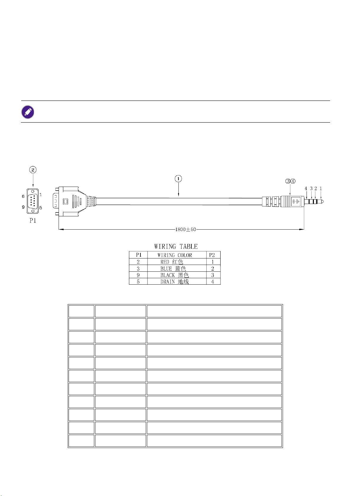
Wire arrangement
RS232 In/Out: 2.5mm phone jack and support below cable
DB-9 connector pin assignment (P1):
3
Page 4

Communication setting
Baud rate select: 9600bps (fixed)/ Data bits: 8 bits (fixed)
Parity: None (fixed)/ Stop Bits: 1(fixed)
Command message reference
PC sends to Monitor command packet followed by "CR". Every time PC sends control command to the
Monitor, the Monitor shall response as follows:
1. If the message is received correctly, it will send "+" (02Bh) followed by "CR" (00Dh).
2. If the message is received incorrectly, it will send "-" (02Dh) followed by "CR" (00Dh).
Connections and communication settings
Choose one of the connections and set up properly before RS232 control.
RS232 serial port connection
4
Page 5
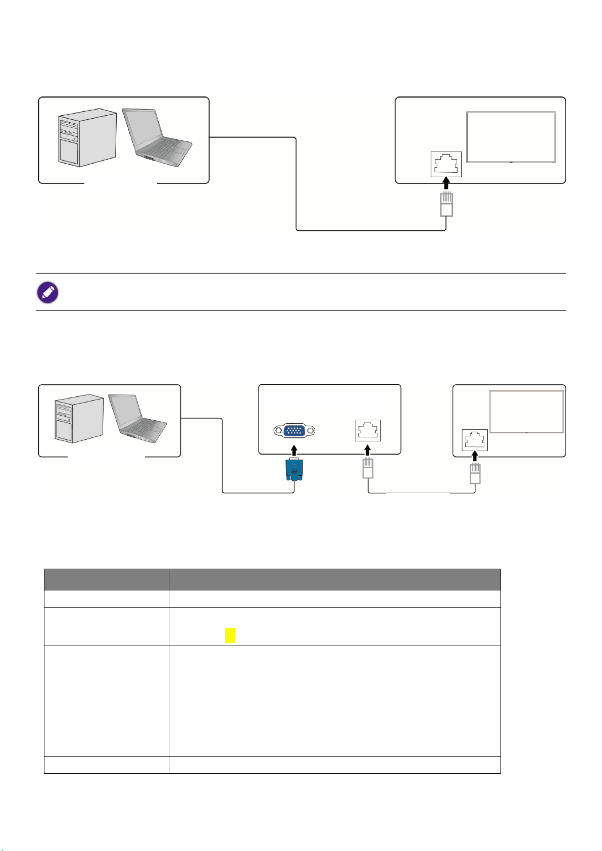
RS232 via LAN
Find the Wired LAN IP address of the connected display from the OSD menu and make sure the display and the computer
are within the same network.
Item
Description
Length
Total Bytes of Message excluding "CR"
Display ID
Identification for each display
Display ID is “01” for LAN control & RS232 control
Command Type
Identify command type,
"s" (0x73h): Set Command
"g" (0x67h): Get Command "r"
(0x72h): Reply Command
"+" (0x2Bh): Valid command Reply
"-" (0x2Dh): Invalid command Reply
Command
Function command code: One byte ASCII code
D-Sub 9 pin
PC or laptop
LAN cable
RJ45 port on a display
HDBaseT compatible device
D-Sub 9 pin
RJ45
RJ45 port on a display
LAN cable
PC or laptop
IP Protocol Port: 4660
RS232 via HDBaseT
Protocol Command Description
5
Page 6
Value [1~3]
Three bytes ASCII that defines the value
CR
0x0D
Set-function listing
Item
Description
Length
Total Bytes of Message excluding "CR"
Display ID
Identification for each display
Display ID is “01” for LAN control & RS232 control
Command Type
Identify command type, "s"
(0x73h): Set Command
Command
Function command code: One byte ASCII code
Value [1~3]
Three bytes ASCII that defines the value
CR
0x0D
Name
Length
ID
Command type
Command
Value1
Value2
Value3
CR
Byte count
1 Byte
2 Byte
1 Byte
1 Byte
1 Byte
1 Byte
1 Byte
1 Byte
Bytes order
1
2~3 4 5 6 7 8 9
Name
Length
ID
Command type
CR
Byte count
1 Byte
2 Byte
1 Byte
1 Byte
Bytes order
1
2~3 4 5
Name
Length
ID
Command type
Command
Value1
Value2
Value3
CR
Hex
0x38
0x30 0x31
0x73
0x24
0x30
0x37
0x36
0x0D
Name
Length
ID
Command type
CR
Hex
0x34
0x30 0x31
0x2B
0x0D
The PC can control the LCD Monitor for specific actions. The Set-Function command allows you to control the LCD monitor
behavior in a remote sit through the RS232 port. The
Set-Function packet format consists of 11 bytes.
Set-function description
Set-function format
Send: (Command Type="s")
Reply: (Command Type="+" or "-")
Example 1: Set Brightness as 76 and this command is valid.
Send (Hex Format)
Reply (Hex Format)
6
Page 7

Example 2: Set Brightness as 176 and this command is NOT valid.
Name
Length
ID
Command type
Command
Value1
Value2
Value3
CR
Hex
0x38
0x30 0x31
0x73
0x24
0x31
0x37
0x36
0x0D
Name
Length
ID
Command type
CR
Hex
0x34
0x30 0x31
0x2D
0x0D
Name
Length
ID
Command type
Command
Value1
Value2
Value3
CR
Hex
0x38
0x30 0x31
0x73
0x39
0x30
0x35
0x30
0x0D
Name
Length
ID
Command type
CR
Hex
0x34
0x30 0x31
0x2D
0x0D
Name
Length
ID
Command type
Command
Value1
Value2
Value3
CR
Hex
0x38
0x30 0x31
0x73
0x39
0x31
0x31
0x35
0x0D
Name
Length
ID
Command type
CR
Hex
0x34
0x30 0x31
0x2D
0x0D
Send (Hex Format)
Reply (Hex Format)
Example 3: Set Balance as 50 this command is valid.
Send (Hex Format)
Reply (Hex Format)
Example 4: Set Balance as 115 this command is Not valid.
Send (Hex Format)
Reply (Hex Format)
7
Page 8

Set-function table
Set Function
Len
ID
Cmd
Type
Cmd
Code
(Hex)
RS232/LAN
Remark
Power
8
s 21
000: Standby
001: On
Video Source
8
s 22
000 : VGA
001 : HDMI1
002: HDMI2
003 : AV
004 : YPbPr
006 : DVI
007 : DisplayPort
010 : Network
011: USB Display
102 : OPS
Contrast
8
s 23
000 ~ 100
Brightness
8
s 24
000 ~ 100
Sharpness
8
s 25
000 ~ 020
Picture Reset
8
s 26
000
Aspect Ratio
8
s 31
000 : Auto Zoom
001 : Movie expand 16:9
002 : Wide
003 : Unscaled
004 : 4:3
Language
8
s 32
000: English
001: Français
002: Español
003: 繁中
004: 简中
006: German
007: Dutch
008: Polish
009: Russia
010:Czech
011:Danish
012:Swedish
013:Italian
9 014:Romanian
8
Page 9

015:Norwegian
016:Finnish
017:Greek
019:Arabic
020:Japanse
021:Thailand
022:Korean
Sound Mode
8
s 33
000: Personal
001: Original
002: Movie
003: Music
004: Game
005: News
Volume
8
s 35
000 ~ 060
Mute
8
s 36
000: Off
001: On
Treble
8
s 37
000 ~ 016
OSD value=RS232 value-8
Bass
8
s 38
000 ~ 016
OSD value=RS232 value-8
Balance
8
s 39
000 ~ 016
OSD value=RS232 value-8
Surround
8
s 3A
000: Off
001: On
Sound Reset
8
s 3B
000
Value don't care
Monitor ID
8
s 3D
001 ~ 098
Remote
control
8
s 40
000 : Vol+
001 : Vol-
002 : mute key
010 : Remote up
011 : Remote down
012 : Remote left
013 : Remote right
014 : Remote OK
020 : Remote Menu
021 : Remote Source
022 : Remote Exit
IR Control
8
s 42
000: Disable
001: Enable
Button&IR
Control
8
s 43
000: Disable
All the buttons at both keypad
board and remote controller have
no function.
Page 10

001: Enable
Button
Control
8
s 45
000: Disable
All the buttons at the keypad board
have no function
001: Enable
Image
Retention
8
s 47
000: Off
001: On
OSD Info Box
8
s 5B
000: Off
001: On
All Reset
8
s 7E
000
Value don't care
Picture Mode
8
s 81
000 : Personal
001 : Vivid
002 : Natural
003 : Standard
004: Movie
005: Photo
006: Energy saving
Chroma
(Color)
8
s 82
000 ~ 100
Hue 8 s 83
000 ~ 100
OSD value=RS232 value-50
Backlight
8
s 84
000 ~ 100
Adaptive
Contrast
8
s 85
000: Off
001: Minium
002: Medium
003: Maxium
Tint 8 s 86
000: Cool
001: Normal
002: Warm
003: Custom
Speaker
8
s 89
000: Off
001: On
Auto
Adjustment
Execute
8
s 8F
000
For VGA only, execute auto
adjustment.
Auto Search
8
s 96
000: Off
001: On
RTC Year
8
s 98
000 ~ 099
Ex: value=012 means Year 2012
If the setting is illegal (Ex: Year
2013 doesn't have the date
10
Page 11

Feb/29), return "Invalid Command
Reply".
RTC Month
8
s 99
001 ~ 012
Ex: value=001 means January
If the setting is illegal (Ex: Februrary
doesn't have the date Feb/31),
return "Invalid Command Reply".
RTC Day
8
s 9A
001 ~ 031
If the setting is illegal (Ex: Day31
doesn't exist in April), return
"Invalid Command Reply".
RTC Hour
8
s 9B
000 ~ 023
RTC Minute
8
s 9C
000 ~ 059
H Monitor
8
s A4
001 ~ 015
V Monitor
8
s A5
001 ~ 015
Tiling
Position
8
s A6
001 ~ 255
Frame Comp.
8
s A8
000: Off
001: On
Power Save
8
s A9
000: Off
001: Low
002: High
Display Wall
LED
8
s AE
000: Off
001: On
Display Wall
Power On
Delay
8
s AF
000 ~ 060
000 : off
001 : auto
002 ~ 060 : 2 ~ 60 sec
On/Off Timer
14
s E0
Byte1~Byte9
(1) Byte1: Decide which Timer is
selected, and its enable/disable
setting.
Byte1[3:0]=0x1~0x07. There are
totally 7 Timers, this value is
used to decide which Timer is
selected.
Byte1[7]: Reserved, should be 0.
Byte1[6]: The Timer is enable or
not. Byte1[6]=1 means enable.
Byte1[5]: The On Timer is enable
or not. Byte1[5]=1 means
Note: Some of the Video Sources
are not supported if the model
doesn't have this feature..
Ex: Byte1=0x01 means the Timer
no.1 is selected and disable.
Ex: Byte1=0x41 means the Timer
no.1 is select and enable, and its
both On and Off Timers are disable.
Ex: Byte1=0x61 means the Timer
no.1 is select and enable, and its
On Timer is enable, Off Timer is
disable.
11
Page 12

enable.
Byte1[4]: The Off Timer is
enable or not. Byte1[4]=1 means
enable.
(2) Byte2: The Day of the On/Off
Timer. bit0 for Sunday, bit1 for
Monday, bit2 for Tuesday, bit3
for Wednesday, bit4 for
Thursday, bit5 for Friday, bit6
for Saturday, bit7 for Everday.
(3) Byte3: The Hour of the On
Timer. Byte3=0x00~0x17.
(4) Byte4: The Minute of the On
Timer. Byte4=0x00~0x3B.
(5) Byte5: The Hour of the Off
Timer. Byte5=0x00~0x17.
(6) Byte6: The Minute of the Off
Timer. Byte6=0x00~0x3B.
(7) Byte7: Select the Video
Source.
0x00 : VGA, 0x01 : HDMI1, 0x02:
HDMI2, 0x03 : AV, 0x04 : YPbPr,
0x06 : DVI, 0x07 : DisplayPort
0x0A : Network, 0x0B : USB
Display, 0x66 : OPS, 0xFF :
Default (Last Channel)
(8) Byte8~9 are reserved, and
should be 0x00.
Ex: Byte1=0x71 means the Timer
no.1 is select and enable, and its
both On and Off Timers are enable.
Ex: Byte1=0x53 means the Timer
no.3 is select and enable, and its
On Timer is disable, Off Timer is
enable.
Ex: Byte2=0x02 means the Timer is
on Monday.
Ex: Byte3=0x08, Byte4=0x1E means
the On Timer is at 8:30.
Ex: Byte5=0x17, Byte6=0x00 means
the Off Timer is at 23:00.
Ex: Byte7=0x00 means the selected
Video Source is VGA.
12
Page 13

Get-function listing
Item
Description
Length
Total Bytes of messages excluding "CR"
Display ID
Identification for each of display
Display ID is “01” for LAN control & RS232 control
Command Type
Identify command type,
"g" (0x67h): Get Command
Command
Function command code: One byte ASCII code
Value [1~3]
Three bytes ASCII that defines the value
NOTE: To get backlight senor, thermal sensor, and ambient sensor, you
need four bytes ASCII that defines the value and the length is 9.
CR
0x0D
Name
Length
ID
Command type
Command
Value1
Value2
Value3
CR
Byte count
1 Byte
2 Byte
1 Byte
1 Byte
1 Byte
1 Byte
1 Byte
1 Byte
Bytes order
1
2~3 4 5 6 7 8 9
Name
Length
ID
Command type
Command
Value1
Value2
Value3
CR
Byte count
1 Byte
2 Byte
1 Byte
1 Byte
1 Byte
1 Byte
1 Byte
1 Byte
Bytes order
1
2~3 4 5 6 7 8 9
Name
Length
ID
Command type
CR
Byte count
1 Byte
2 Byte
1 Byte
1 Byte
Bytes order
1
2~3 4 5
The PC can interrogate the LCD Monitor for specific information. The Get-Function packet format
consists of 5 bytes which are similar to the Set-Function packet structure. Note that the "Value" byte is
always = 00.
Get-function description
Get-function format
Send: (Command Type="g")
Reply: (Command Type="r" or "-")
If the Command is valid, Command Type ="r"
If the Command is Not valid, Command Type="-"
13
Page 14

Name
Length
ID
Command type
Command
Value1
Value2
Value3
CR
Hex
0x38
0x30 0x31
0x67
0x62
0x30
0x30
0x30
0x0D
Name
Length
ID
Command type
Command
Value1
Value2
Value3
CR
Hex
0x38
0x30 0x31
0x72
0x62
0x30
0x36
0x37
0x0D
Name
Length
ID
Command type
Command
Value1
Value2
Value3
CR
Hex
0x38
0x30 0x31
0x67
0X39
0x30
0x30
0x30
0x0D
Name
Length
ID
Command type
Command
Value1
Value2
Value3
CR
Hex
0x38
0x30 0x31
0x72
0x39
0x30
0x33
0x32
0x0D
Name
Length
ID
Command type
Command
Value1
Value2
Value3
CR
Hex
0x38
0x30 0x31
0x67
0XD7
0x30
0x30
0x30
0x0D
Name
Length
ID
Command type
CR
Hex
0x34
0x30 0x31
0x2D
0x0D
Name
Length
ID
Command type
Command
Value1
Value2
Value3
Value4
Value5
CR
Hex
0x38
0x30 0x31
0x67
0X76
0x30
0x30
0x30
0x30
0x30
0x0D
Name
Length
ID
Command type
Command
Value1
Value2
Value3
Value4
Value5
CR
Example 1: Get Brightness and this command is valid.
The Brightness value is 67.
Send (Hex Format)
Reply (Hex Format)
Example 3: Get Balance from and this command is valid.
The Balance value is 32.
Send (Hex Format)
Reply (Hex Format)
Example 4: Get Balance, but the Balance command ID is error and it is NOT in the command table.
Send (Hex Format)
Reply (Hex Format)
Example 5: Get Operation time from system and this command is valid.
The System Operation time value is 1786 (ASCII code).
Send (Hex Format)
Reply (Hex Format)
14
Page 15

Hex
0x38
0x30 0x31
0x72
0x76
0x30
0x31
0x37
0x38
0x36
0x0D
Name
Length
ID
Command type
Command
Value1
Value2
Value3
Value4
Value5
CR
Hex
0x38
0x30 0x31
0x67
0XAB
0x30
0x30
0x30
0x30
0x30
0x0D
Name
Length
ID
Command type
Command
Value1
Value2
Value3
Value4
Value5
CR
Hex
0x38
0x30 0x31
0x72
0xAB
0x30
0x30
0x37
0x38
0x36
0x0D
Get Function
Len
ID
Cmd
Type
Cmd
Code
(Hex)
RS232/LAN
Remark
Model Info
20
g 20
(1) Input value: Byte1 - Byte2 Byte3…Byte15
Byte2~Byte11=0x00
Byte1=0x01: Get Customer Name
Byte1=0x02: Get Customer Model
Name
Byte1=0x04: Get Scaler Firmware
Version
Byte1=0x06: Get Serial Number
(2) Return value: Byte1 - Byte2 Byte3…Byte15
The Byte1 value at the return
value should be the same as the
value of Byte1 at input value.
Byte2~Byte15 should be ASCII
format.
Ex: If Customer=Generic,
Byte1=0x01, Byte2='G',
Byte3='e',...Byte8='c',
Byte9~Byte11=0x00.
Ex: If the Scaler Firmware
MDA :
Byte1=0x01: Get Customer
Name -> BENQ
Byte1=0x02: Get Customer
Model Name -> by project
Byte1=0x03: Get Qisda Model
Name
Byte1=0x04: Get Scaler
Firmware Version
Byte1=0x05: Get LAN Firmware
Version
Byte1=0x06: Get Serial Number
Example 6: Get CO2 Value from System and this command is valid.
The lux value is 786 (ASCII code).
Send (Hex Format)
Reply (Hex Format)
PC Get-function command
15
Page 16

Version=1.02, Byte1=0x03,
Byte2='1', Byte3='.', Byte4='0',
Byte5='2', Byte6~Byte11=0x00.
Signal Status
8
g 22
000: Signal unstable
001: Signal stable (Active Sync
exists)
Treble
8
g 37
000~016
OSD value=RS232 value-8
Bass
8
g 38
000~016
OSD value=RS232 value-8
Balance
8
g 39
000~100
OSD value=RS232 value-50
Surround
8
g 3A
000: Off
001: On
OSD Info Box
8
g 5D
000: Off
001: On
Contrast
8
g 61
000 ~ 100
Brightness
8
g 62
000 ~ 100
Sharpness
8
g 63
000 ~ 020
Sound Mode
8
g 65
000: Personal
001: Original
002: Movie
003: Music
004: Game
005: News
Volume
8
g 66
000 ~ 060
Mute
8
g 67
000: Off
001: On
IR Control
8
g 68
000: Disable
All the buttons at the remote
controller have no function
001: Enable
Button&IR
Control
8
g 69
000: Disable
All the buttons at both keypad
board and remote controller
have no function.
16
Page 17

001: Enable
Video Source
8
g 6A
000 : VGA
001 : HDMI1
002: HDMI2
003 : AV
004 : YPbPr
006 : DVI
007 : DisplayPort
010 : Network
011: USB Display
102 : OPS
Power
8
g 6C
000: Standby
001: On
Thermal
Sensor Value
10
g 71
(1) Input value: Byte1Byte2-...Byte5
(a) Byte1=0x01: Get the thermal
sensor value from main board
0x02: Get
the thermal sensor value from
keypad board
(b) Byte2~Byte5 are reserved,
should b 0x00
(2) Return value: Byte1Byte2-...Byte5
(a) Byte1=0x01: The thermal
sensor value is from main board
0x02: The thermal
sensor value is rom kaypad board
(b) Byte2: If the thermal value is
>=0, Byte2='+' (0x2B)
If the thermal value is <0, Byte2='' (0x2D)
(c) Byte3~Byte5: The absolute
value of the temperature, in ASCII
format.
Ex: If the temperature 5℃is
from main board, the return
value should be: Byte1=0x01,
Byte2=0x2B, Byte3=0x30,
Byte4=0x30, Byte5=0x35.
Ex: If the temperature -15℃is
from keypad board, the return
value should be: Byte1=0x02,
Byte2=0x2D, Byte3=0x30,
Byte4=0x31, Byte5=0x35.
Image
Retention
8
g 72
000: Off
001: On
Button Control
8
g 73
000: Disable
All the buttons at the keypad
board have no function
17
Page 18

001: Enable
Monitor ID
8
g 75
001 ~ 098
Operation
Time
10
g 76
00000 ~ 65535
unit is hour
Aspect Ratio
8
g 77
000 : Auto Zoom
001 : Movie expand 16:9
002 : Wide
003 : Unscaled
004 : 4:3
Language
8
g 78
000: English
001: Français
002: Español
003: 繁中
004: 简中
006: German
007: Dutch
008: Polish
009: Russia
010:Czech
011:Danish
012:Swedish
013:Italian
014:Romanian
015:Norwegian
016:Finnish
017:Greek
019:Arabic
020:Japanse
021:Thailand
022:Korean
Display Wall
LED
8
g AE
000: OFF
001: ON
Display Wall
Power On
Delay
8
g AF
000 : off
000 : off
001 : auto
002 ~ 060 : 2 ~ 60 sec
001 : auto
002 ~ 060 : 2 ~ 60 sec
Picture Mode
8
g B1
000: Personal
001: Original
002: Movie
18
Page 19

003: Music
004: Game
005: News
Chroma (Color)
8
g B2
000 ~ 100
Hue
8
g B3
000 ~ 100
Backlight
8
g B4
000 ~ 100
Adaptive
Contrast
8
g B5
000: Off
001: Minium
002: Medium
003: Maxium
Tint
8
g B6
000: Cool
001: Normal
002: Warm
003: Custom
Speaker
8
g B9
000: Off
001: On
Auto Search
8
g C6
000: Off
001: On
RTC Year
8
g C8
000 ~ 099
Ex: value=012 means Year 2012
If the RTC is not enable, return
"Invalid Command Reply"
RTC Month
8
g C9
001 ~ 012
Ex: value=001 means January
If the RTC is not enable, return
"Invalid Command Reply"
RTC Day
8
g CA
001 ~ 031
If the RTC is not enable, return
"Invalid Command Reply"
RTC Hour
8
g CB
000 ~ 023
If the RTC is not enable, return
"Invalid Command Reply"
RTC Minute
8
g CC
000 ~ 059
If the RTC is not enable, return
"Invalid Command Reply"
H Monitor
8
g D4
001 ~ 010
V Monitor
8
g D5
001 ~ 010
Tiling Position
8
g D6
000 ~ 255
Frame Comp.
8
g D8
000: Off
001: On
Power Save
8
g D9
000: Off
001: Low
002: High
19
Page 20

On/Off Timer
14
g E0
Input value: Byte1 - Byte2 Byte3…Byte9
(1) Byte1[3:0]: The Number of the
On/Off Timer. There are totally 7
On/Off Timers, and this byte is
used to selected which timer is
going to be accessed.
(2) Byte1[7:4] is reserved, should
be 0.
(3) Byte2~9 are reserverd, should
be 0x00.
Return value: Byte1 - Byte2 Byte3…Byte9
(1) Byte1[3:0]: Should retuen the
same value as Byte1 at Input
value.
Byte1[7]: Reserved, should be 0.
Byte1[6]: The Timer is enable or
not. Byte1[6]=1 means enable.
Byte1[5]: The On Timer is enable
or not. Byte1[5]=1 means enable.
Byte1[4]: The Off Timer is enable
or not. Byte1[4]=1 means enable.
(2) Byte2: The Day of the On/Off
Timer. bit0 for Sunday, bit1 for
Monday, bit2 for Tuesday, bit3 for
Wednesday, bit4 for Thursday,
bit5 for Friday, bit6 for Saturday,
bit7 for Everday.
(3) Byte3: The Hour of the On
Timer. Byte3=0x00~0x17.
(4) Byte4: The Minute of the On
Timer. Byte4=0x00~0x3B.
(5) Byte5: The Hour of the Off
Timer. Byte5=0x00~0x17.
(6) Byte6: The Minute of the Off
Timer. Byte6=0x00~0x3B.
(7) Byte7: Select the Video
Source.
0x00 : VGA, 0x01 : HDMI1, 0x02:
See the return value examples
below:
Ex: Byte1=0x01 means the Timer
no.1 is selected and disable.
Ex: Byte1=0x41 means the Timer
no.1 is select and enable, and its
both On and Off Timers are
disable.
Ex: Byte1=0x61 means the Timer
no.1 is select and enable, and its
On Timer is enable, Off Timer is
disable.
Ex: Byte1=0x71 means the Timer
no.1 is select and enable, and its
both On and Off Timers are
enable.
Ex: Byte1=0x53 means the Timer
no.3 is select and enable, and its
On Timer is disable, Off Timer is
enable.
Ex: Byte2=0x02 means the Timer
is on Monday.
Ex: Byte3=0x08, Byte4=0x1E
means the On Timer is at 8:30.
Ex: Byte5=0x17, Byte6=0x00
means the Off Timer is at 23:00.
Ex: Byte7=0x00 means the
selected Video Source is VGA.
20
Page 21

HDMI2, 0x03 : AV, 0x04 : YPbPr,
0x06 : DVI, 0x07 : DisplayPort
0x0B : USB Display, 0x66 : OPS
(8) Byte8~9 are reserved, and
should be 0x00.
Network
Setting
14
g E1
Input Value: Byte1 - Byte2 Byte3…Byte9
(1) Byte1=0x00: IP Setup Mode
Byte1=0x01: IP Address
Byte1=0x02: Get Subnet
Mask
Byte1=0x03: Default
Gateway
Byte1=0x04: Primary DNS
Byte1=0x05: Secondary
DNS
Byte1=0x06: MAC Address
(2) Byte2~9 are reserved, should
be 0x00.
Return value: Byte1 - Byte2 Byte3…Byte9
The Byte1 at the return value
should be the same as the value
of Byte1 at Input value.
Byte2~Byte15 should be hex
value format
(1) If Byte1=0x00(IP Setup Mode)
at Input value, the return value
should be
Byte1=0x00
Byte2=0x00: Manual
Ex: Subnet Mask=255.255.255.0,
the return value:
Byte1=0x02, Byte2=0xFF,
Byte3=0xFF, Byte4=0xFF,
Byte5=0x00, Byte6~9=0x00.
21
Page 22

0x01: DHCP
Byte3~9 are reserved,
should be 0x00.
(2) If Byte1=0x01(IP Address) at
Input value, the return value
should be
Ex: IP
address=169.254.81.38
Byte1=0x01 (same as
Byte1 at Input value)
Byte2=0xA9 (=169),
Byte3=0xFE (=254),
Byte4=0x51(=81), Byte5=0x26
(=38)
Byte6~9 are reserved,
should be 0x00.
(3) If Byte1=0x02~0x05 at Input
value, refer to (2)
(4) If Byte1=0x06(MAC Address)
at Input value, the return value
should be
Ex: MAC
address=00:22:64:7E:2C:82
Byte1=0x06 (same as
Byte1 at Input value)
Byte2=0x00, Byte3=0x22,
Byte4=0x64, Byte5=0x7E,
Byte6=0x2C, Byte7=0x82
Byte8~9 are reserved,
should be 0x00.
22
 Loading...