


LU9915
Digital Projector
Installation Guide
Guide d'installation
Installationsanleitung
Guida all'installazione
Guía de instalación
설치 설명서
安裝指南
安装指南
V1.02
4J.JHG01.001

English
Table of Contents
Notice ..................................................................................................... 3
Ventilation illustration .................................................................................................3
Exhaust vent requirements .........................................................................................3
Voltage switcher ...........................................................................................................4
Caution during installation ..........................................................................................4
Product information ............................................................................. 5
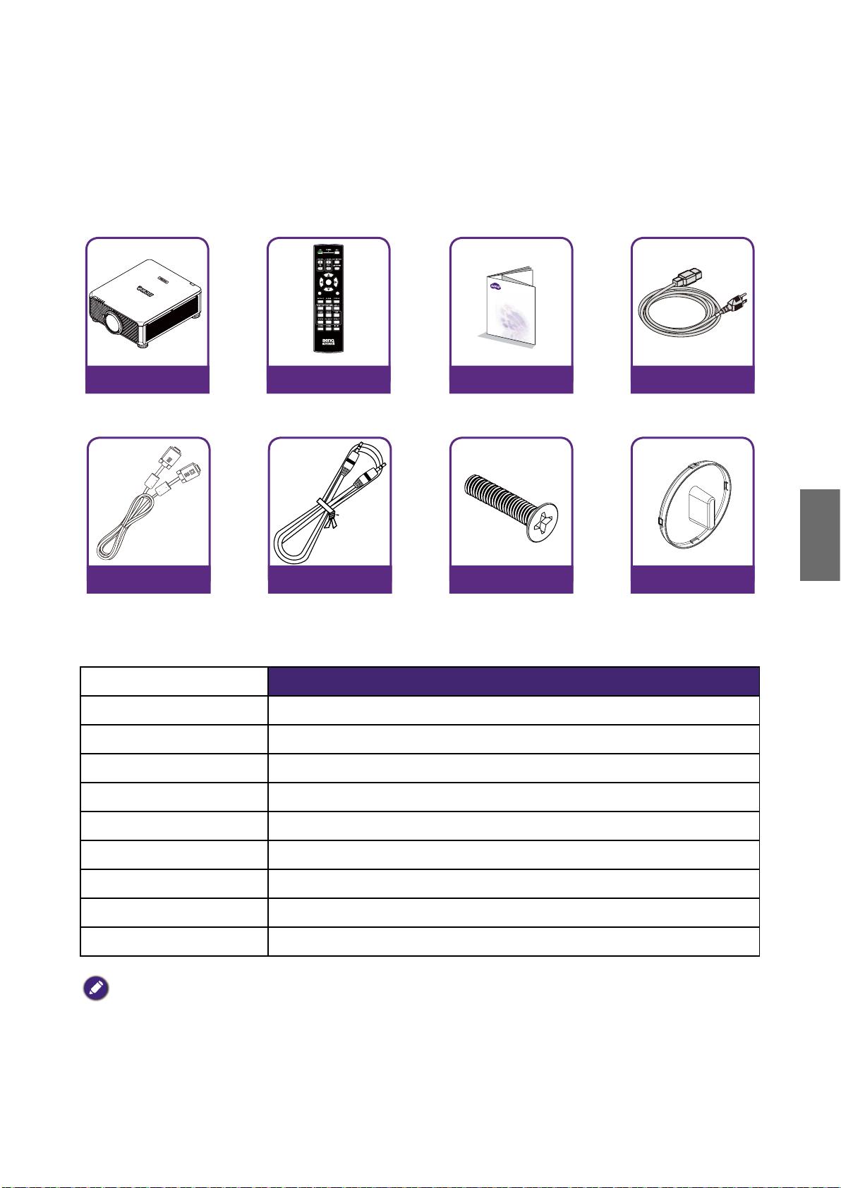
Packing contents ...........................................................................................................5
Projector specifications ................................................................................................5
Terminals .......................................................................................................................6
Remote control .............................................................................................................7
Remote control ID setting ...........................................................................................7
Installation ............................................................................................. 8
Lens specifications ........................................................................................................8
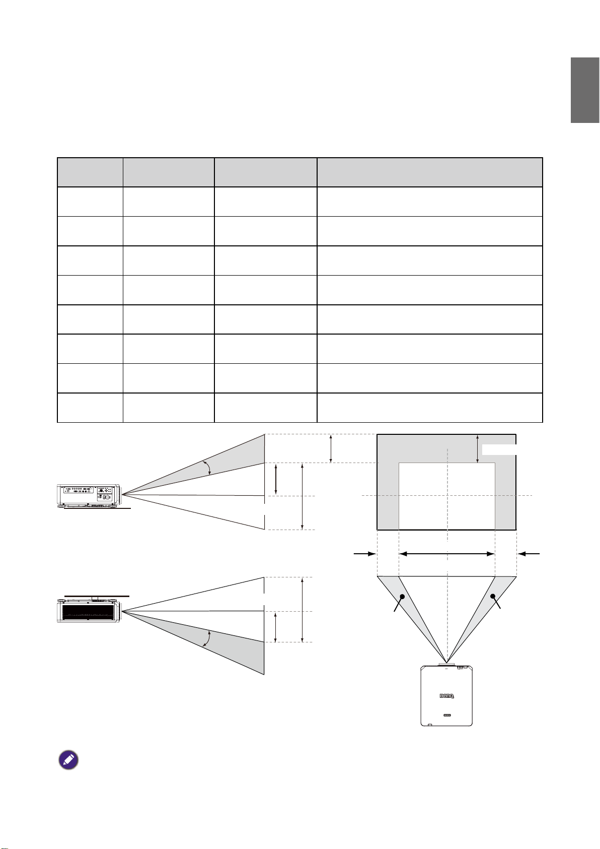
Projection table .............................................................................................................9
Lens shift ........................................................................................................................11
Installation positioning .................................................................................................12
Dimensions ............................................................................................ 13
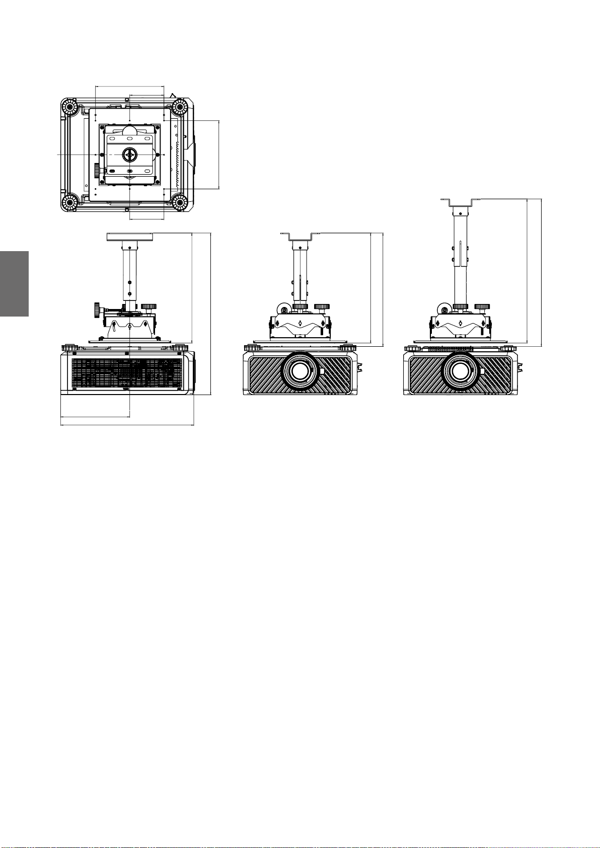
Cabinet dimensions ......................................................................................................13
Ceiling mount hole dimensions ...................................................................................13
Ceiling mount dimensions (CMG6) ............................................................................14
Optional lens dimensions .............................................................................................15
LED indication ....................................................................................... 16
Please visit below website for latest version of User Manual / Installation Guide.
http://business-display.benq.com/
10/8/18
2
Notice
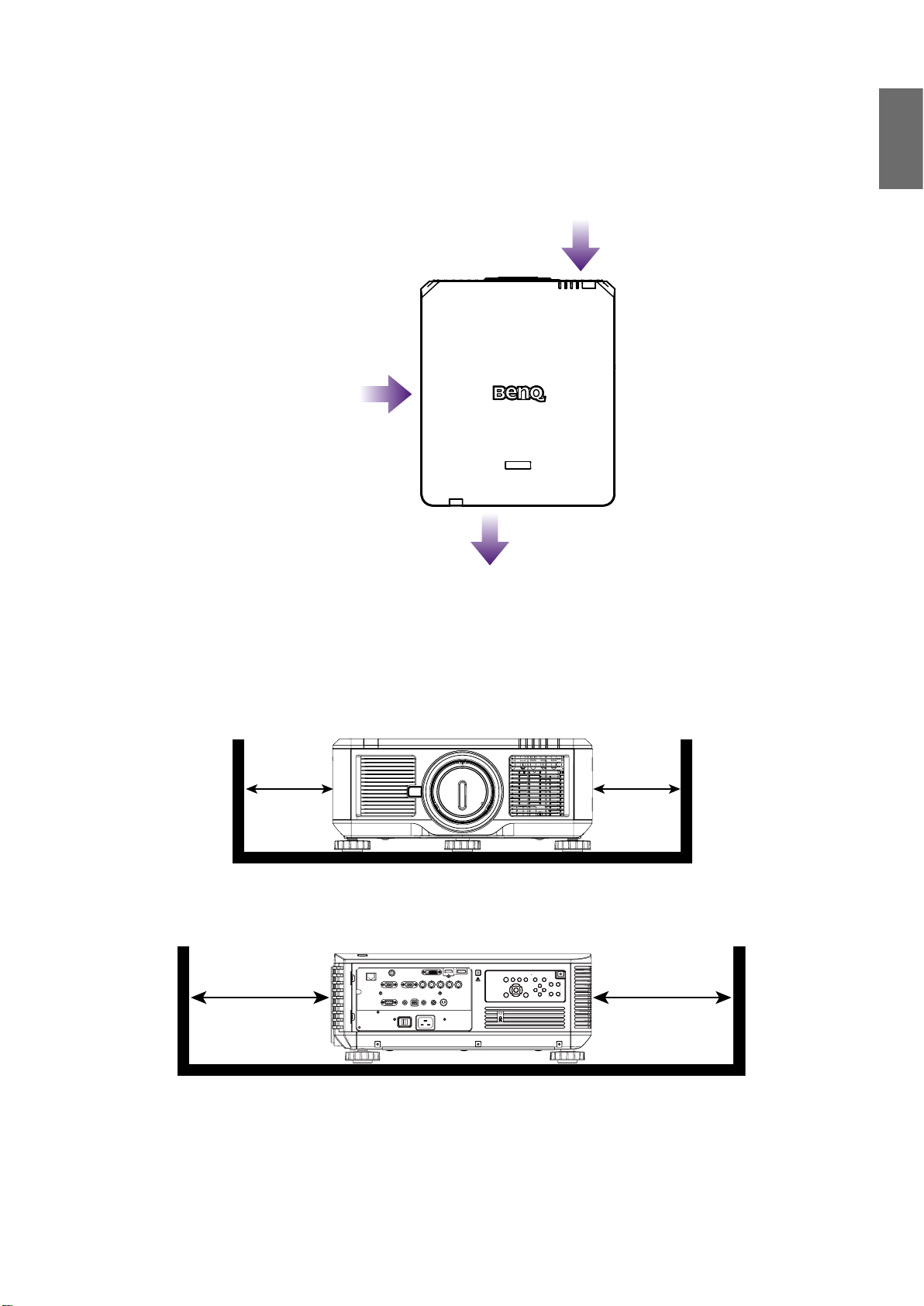
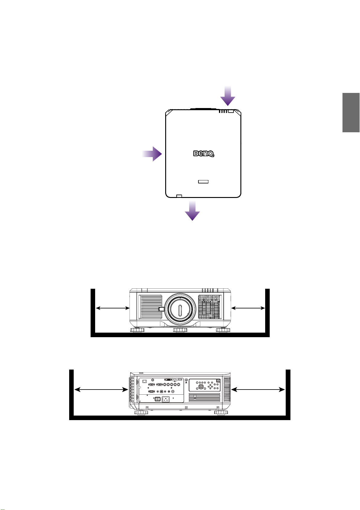
Ventilation illustration
Air inlet
English
Air inlet
Air outlet
Exhaust vent requirements
For proper ventilation of the projector, make sure to leave some space around the projector as
shown in the illustration below:
11.8 in / 30 cm
or greater
19.7 in / 50 cm
or greater
HDBaseT / LAN
3D Sync Out
RGB IN
RS-232 USBTRIGGER
CENTER
AUTO
POWER
SHUTTER
LENS
INPUT
DVI-D
Display Port
HDMI
R/Pr G/Y B/Pb
HV
RGB OUT
WIRE
MENU EXIT
SYNC ASPECT
FOCUS
LENS
SHIFT
ZOOM
11.8 in / 30 cm
or greater
19.7 in / 50 cm
or greater
3
English
Minimum
11.8 in / 30 cm
Minimum
19.7 in / 50 cm
RS-232 USBTRIGGER
Display PortDVI-D
WIRE
R/Pr G/YB/Pb
RGB IN
HV
RGB OUT
HDMI
HDBaseT / LAN
3D Sync Out
MENU EXIT
SHIFT
LENS
FOCUS
ZOOM
INPUT
SYNC ASPECT
LENS
SHUTTER
POWER
AUTO
CENTER
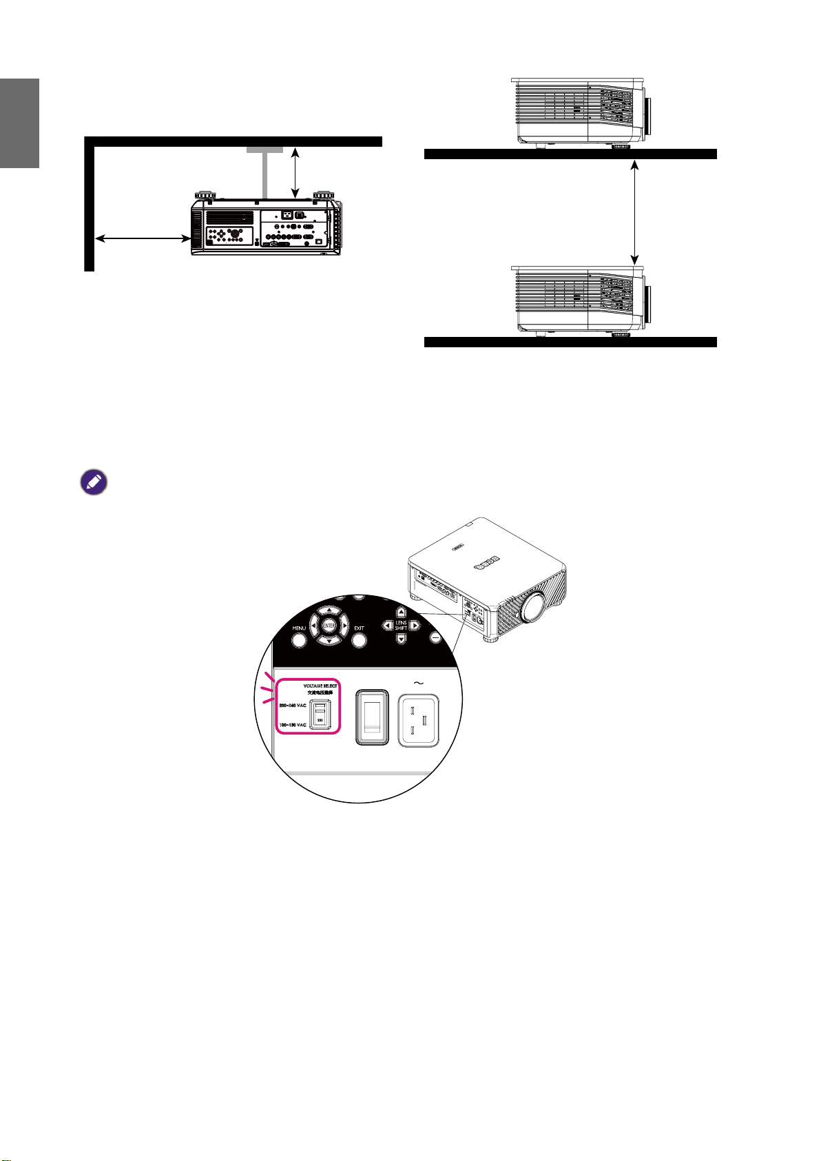
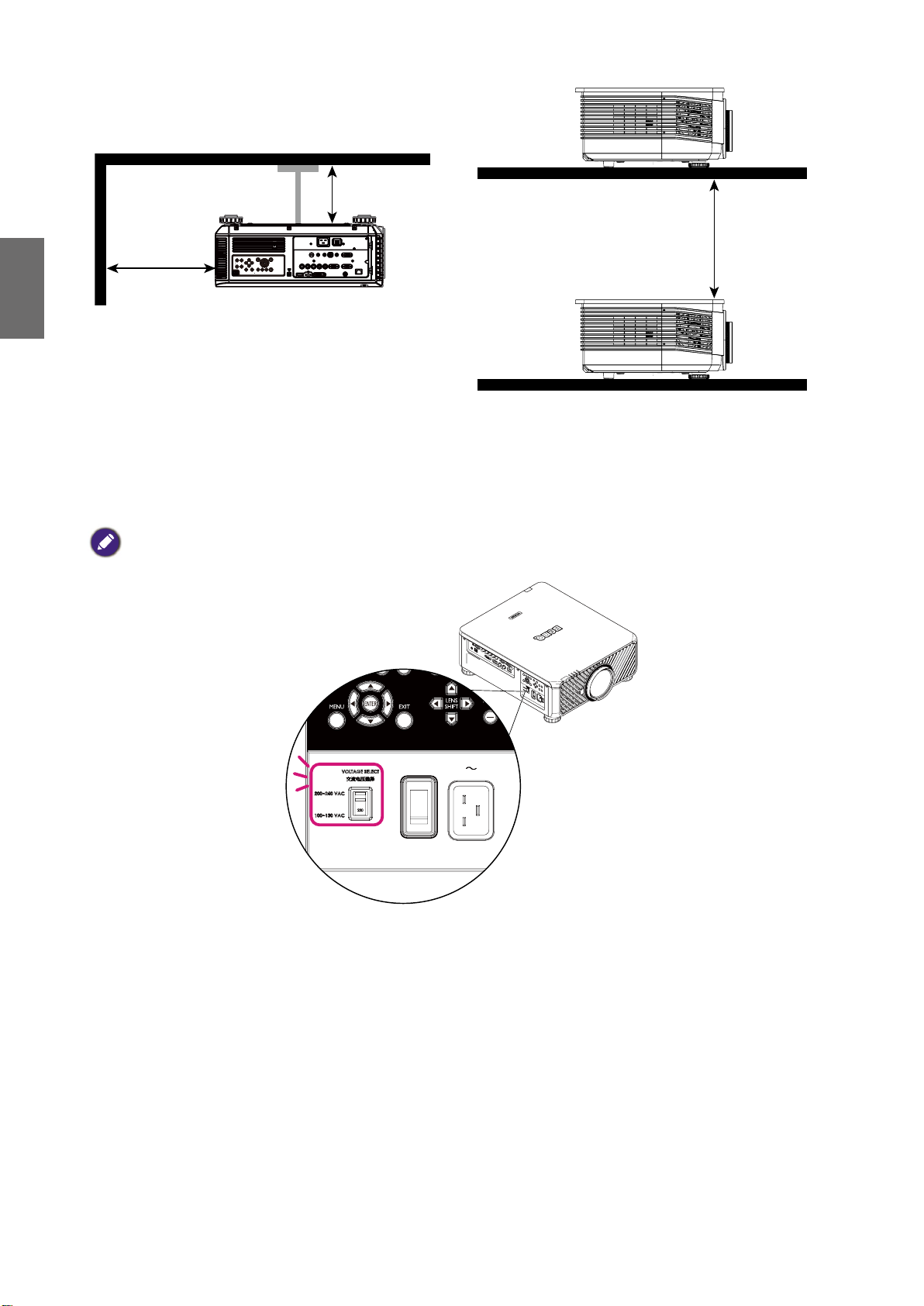
39.3 in / 100 cm
Voltage switcher
Please make sure the Voltage Switch is selected at the right voltage in the region where projector
is being used.
Note:
Default setting is 230V.
Minimum
Caution during installation
• Please turn off projector when changing or removing lens, or it will cause the projector shut
down immediately without normal procedure.
• To avoid damaging the DLP chips, never aim a high-power laser beam into the projection lens.
4
Product information
MENU
EXIT
ENTER
1
4
7089
635
2
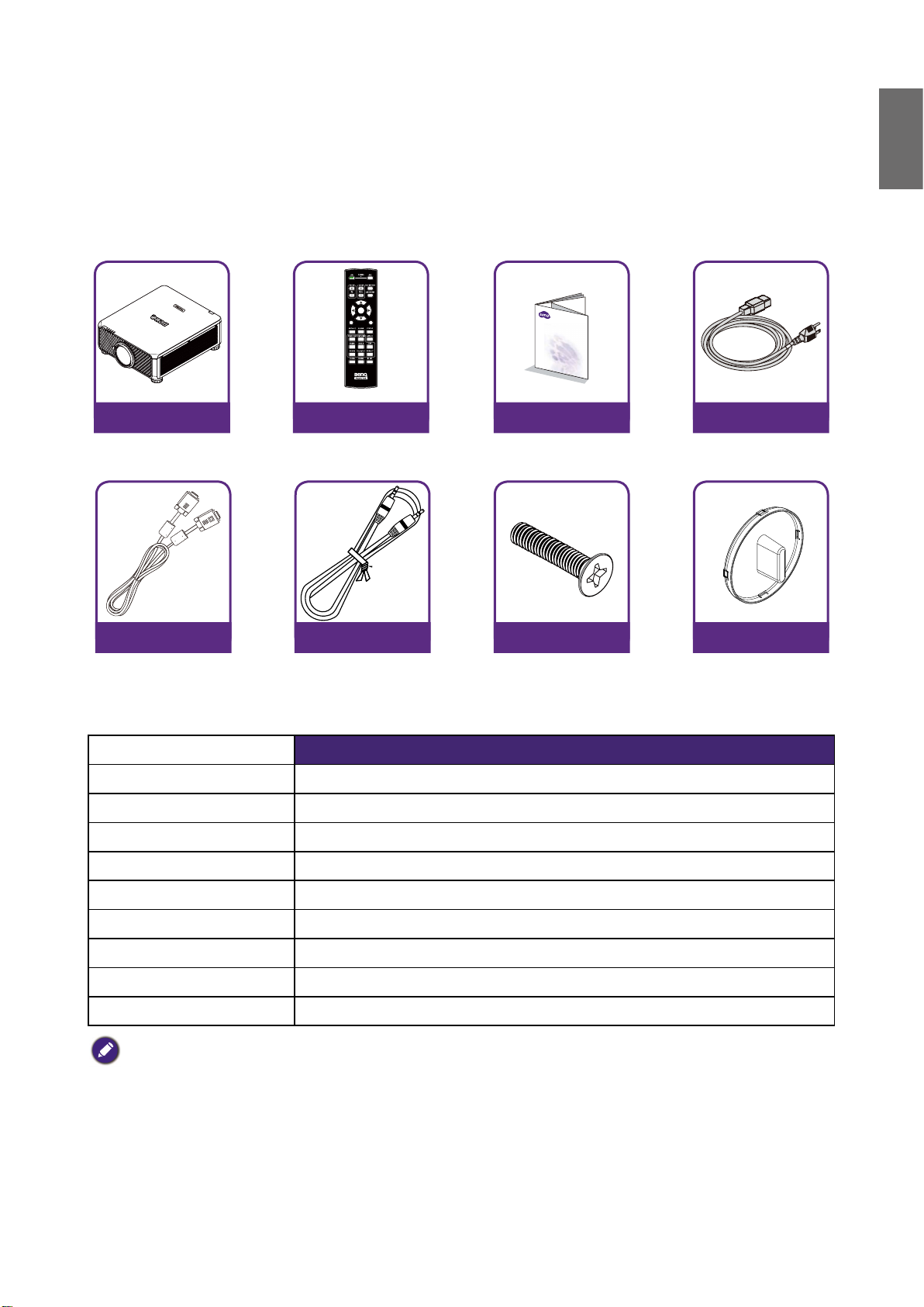
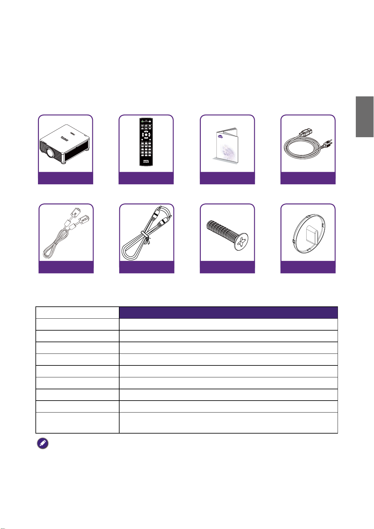
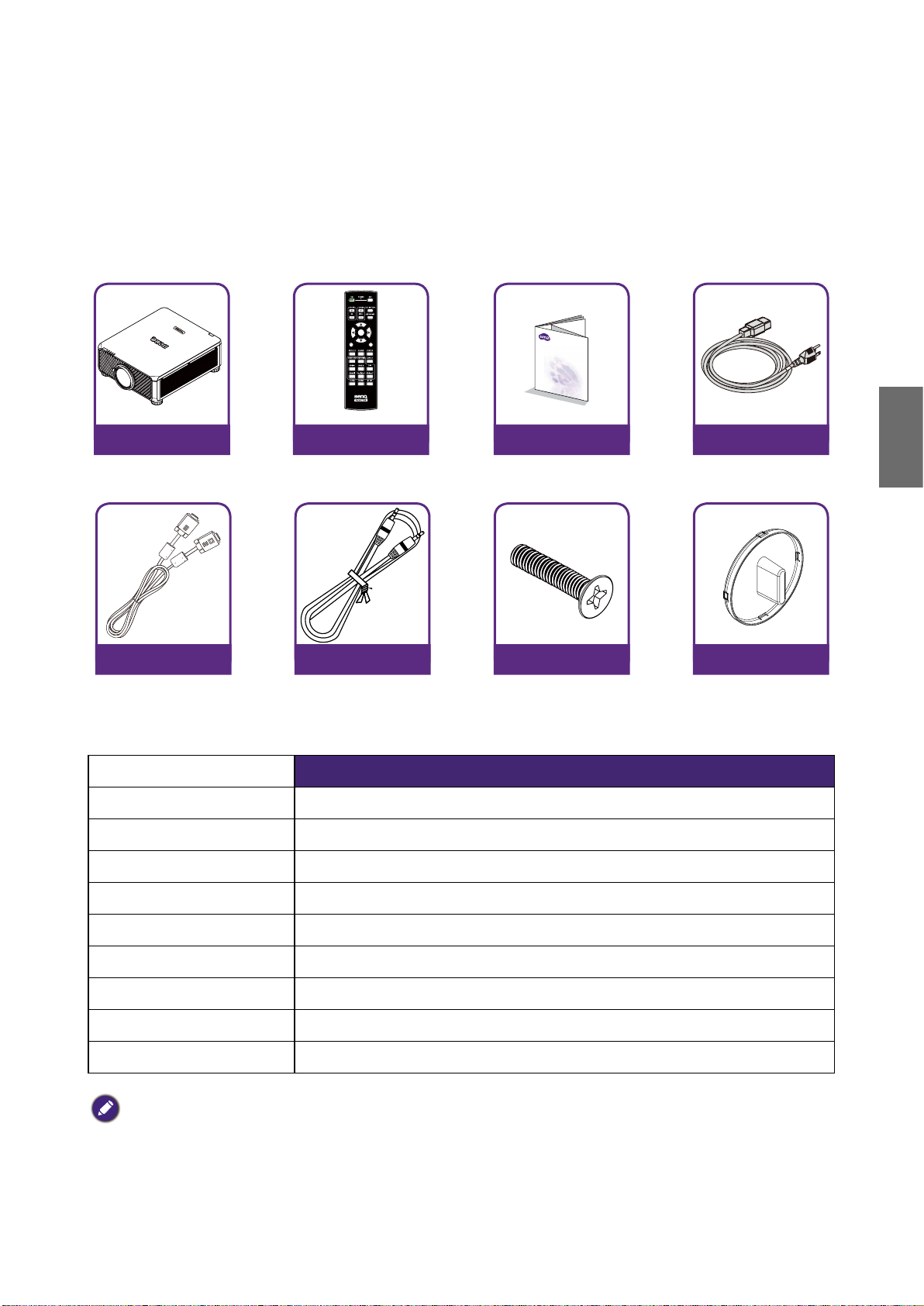
Packing contents
Carefully unpack and verify that you have the items below. Some of the items may not be available
depending on your region of purchase. Please check with your place of purchase.
English
Projector
without lens
VGA cable Wired remote cable
Remote
without AA batteries
Installation guide
Anti-Theft screw Lens hole cap
Projector specifications
Specifications LU9915
Projection system DLP Single 0.67 WUXGA DMD Chip
Native resolution WUXGA (1920 x 1200)
Brightness 10,000 Lumens
Power cable
Aspect ratio 16:10
Light source Laser Light Source
Power consumption 1290W@100V, 1215W@240V
Dimensions 583mm (L) x 500mm (W) x 211mm (H)
Weight 28kg / 61.7 lbs (Lens excluded)
Operation Temperature 32ºF to 104ºF (0ºC to 40ºC )
Note:
• Brightness is supplied by standard lens. The value will vary depending on lenses being installed.
• Brightness output will vary depending on each unit and actual usage.
• Please visit the local website from http://www.benq.com for the latest User Manual.
5
English
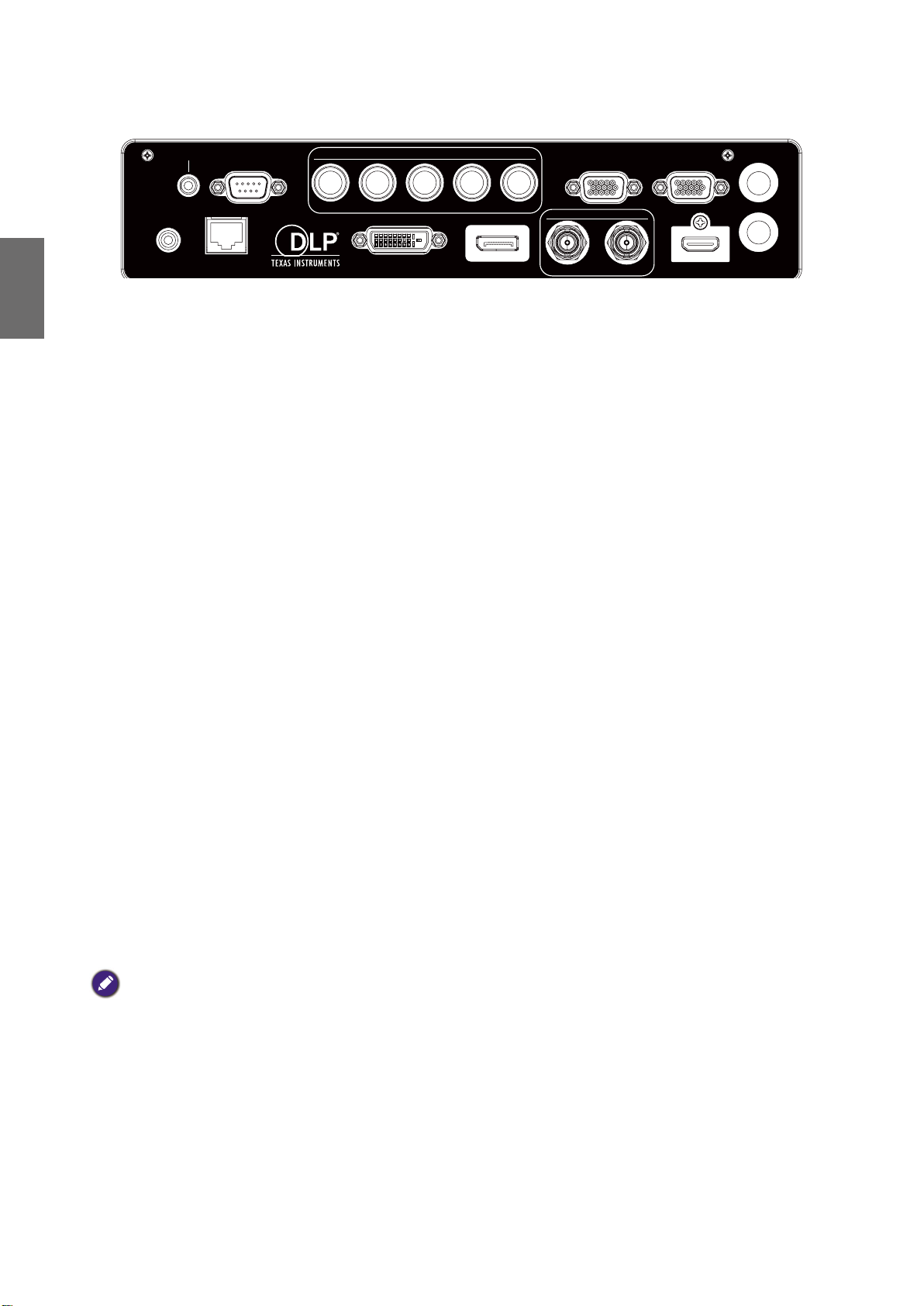
Terminals
TRIGGER
WIRED
REMOTE HDBaseT/LANDVI-D DISPLAYPORT
RS-232TRIGGER
COMPUTER 2
MONITOR OUTCOMPUTER 1
R/PrG/YB/PbHV
3G-SDI
IN
OUT HDMI
3D SYNC OUT
3D SYNC IN
• HDBaseT/LAN
For connection to RJ45 Cat5/Cat6 Ethernet cable to input uncompressed high-definition video
(HD), control signals.
• 3D Sync Out
Connection to 3D IR sync signal transmitter.
• 3D Sync In
Connection to 3D sync signal input.
• DVI-D
Connection to DVI-D source.
• HDMI
Connection to HDMI source.
• DisplayPort
Connection to device or PC featuring DisplayPort.
• 3G-SDI
Connection to 3G-SDI source.
• Computer 1
15-pin VGA port for connection to RGB, component HD source, or PC.
• Computer 2 (V, H, B/Pb, G/Y, R/Pr)
Connection to RGB or YPbPr/YCbCr output signal with BNC type input terminal.
• Monitor Out
Connection to other display equipment for concurrent playback display.
• RS-232
Standard 9-pin D-sub interface for connection to PC control system and projector maintenance.
• TRIGGER
3.5mm mini earphone jack, employs 350mA display relay to provide 12(+/-1.5)V output and
short circuit protection.
• Wired Remote
Connection to input Niles or Xantech compatible IR repeater system.
Note:
Make sure the port is valid before inserting a wired remote controller. The remote controller may be damaged in
case of an invalid port, e.g. a wired remote controller is connected to trigger output.
6
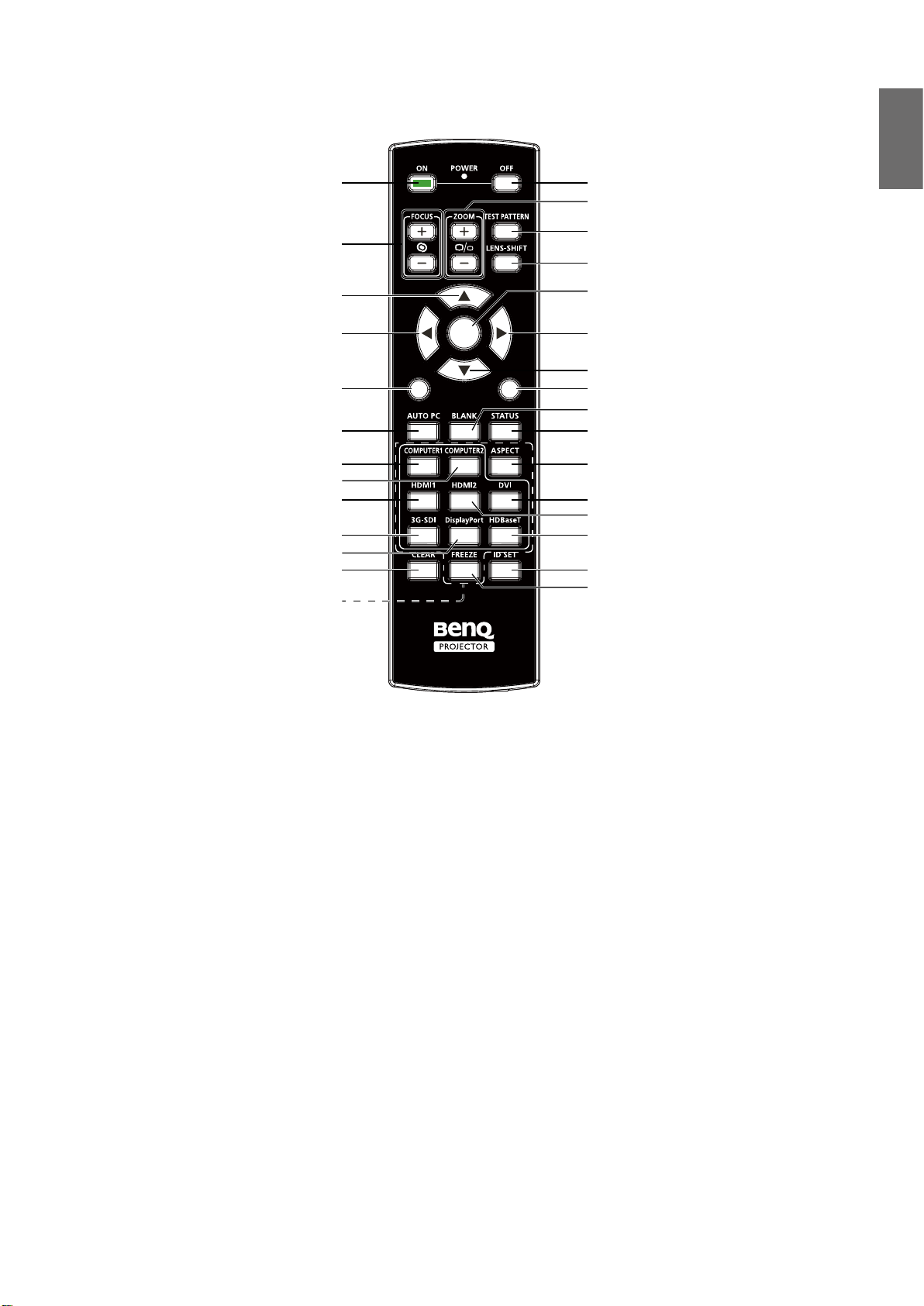
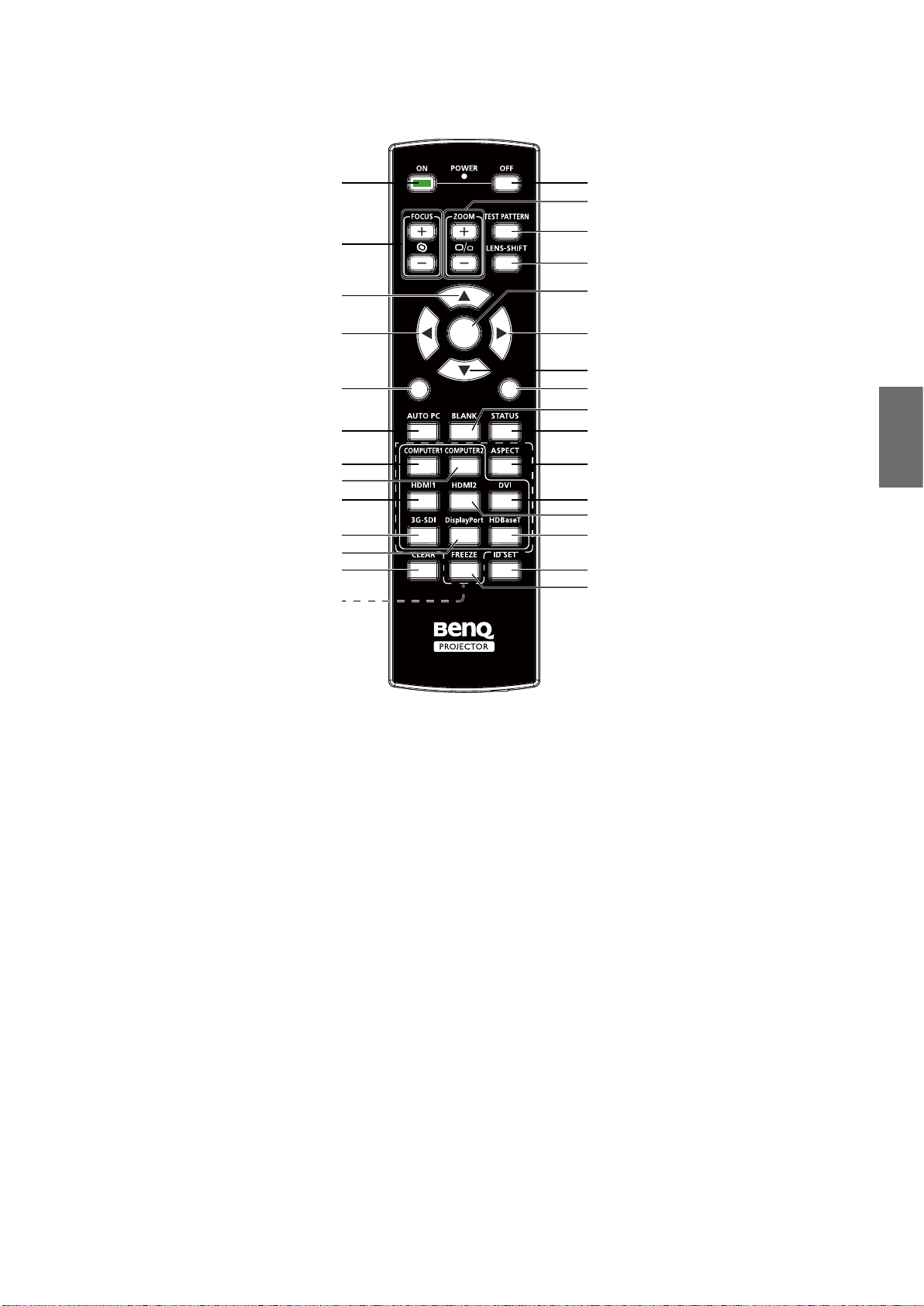
Remote control
89
English
ON OFF
ZOOM +/-
FOCUS +/-
Up
Left
MENU
AUTO PC
COMPUTER 1
COMPUTER 2
HDMI 1
3G-SDI
DisplayPort
CLEAR
Numeric buttons
MENU
TEST PATTERN
LENS-SHIFT
ENTER
ENTER
EXIT
1
4
7
3
2
6
5
0
Right
Down
EXIT
BLANK
STATUS
ASPECT
DVI
HDMI 2
HDBaseT
ID SET
FREEZE
Remote control ID setting
You can set the remote control ID to control the specific projector.
Please set projector ID (from 01 to 99) by using the OSD menus. After setup different ID, the
remote control will only control the matched projector .
Press ID SET + MENU keys together for 5 seconds, the remote control backlight will flash one
time, then into the ID Set mode.
Again click ID SET + MENU keys for 5 seconds (backlight will flash 1 time) to release ID SET
Mode.
After into the ID Set Mode, press ID SET key for 3 seconds.
The remote control LED light will flash and backlight will light. In the meantime, press number to
set the remote control ID.
For example, for setting remote control ID to “01”, please press 0 key for 1 second (LED light
will flash 3 times then back light off), then press 1 key for 1 second (LED light flash 3 times then
backlight off).
For setting remote control ID to “19”, please press 1 key for 1 second, then press 9 key for 1
second.
7
English
Installation
Lens specifications
Model
Name
LS1ST4
LS1ST3 Wide fix 5J.JAM37.011 F=1.85, f=11.6mm 0.76:1 Fixed 910g
LS1ST2 Ultra Wide 5J.JAM37.061
LS1ST1 Wide Zoom 5J.JAM37.021
LS1SD Standard 5J.JAM37.001
LS1LT1 Semi Long 5J.JAM37.051
LS1LT2 Long Zoom1 5J.JAM37.031
LS1LT3 Long Zoom2 5J.JAM37.041
Lens Type
Ultra Short
Throw
BenQ Part
Number
5J.JCY37.002 F=2.0, f=5.64 mm 0.38:1 Fixed 2,710g
Optical spec Throw Ratio Zoom Ratio Weight*
F=1.96~2.3,
f=11.3~14.1mm
F=1.85~2.5,
f=18.7~26.5mm
F=1.7~1.9,
f=26~34mm
F=1.86~2.48,
f=32.9~54.2mm
F=1.85~2.41,
f=52.8~79.1mm
F=1.85~2.48,
f=78.5~121.9mm
0.75~0.93:1 1.25:1 1,280g
1.25~1.79:1 1.41:1 1,090g
1.73~2.27:1 1.3:1 820g
2.22~3.67:1 1.65:1 950g
3.58~5.38:1 1.5:1 1,020g
5.31~8.26:1 1.55:1 1,350g
Note:
The values listed in the table above are average and may vary by model.
8
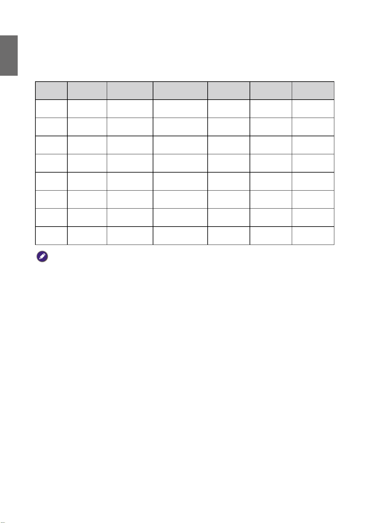
Projection table
Wide Fix Lens, Wide Zoom Lens, STD Lens, Semi Long Zoom1,
Long Zoom 1 Lens, Long Zoom 2 Lens, Ultra Wide Zoom Lens
Lens center
Height (B)
SCREEN
Distance (A)
LU9915
English
Screen Size 5J.JAM37.011 5J.JAM37.021 5J.JAM37.001 5J.JAM37.051
Wide Fix Lens Wide Zoom Lens STD Lens Semi long Zoom1
Diagonal Width Height (B) Distance (A)
Fixed Wide Tele Wide Tele Wide Tele
(inch) (m) (inch) (m) (inch) (m) (inch) (m) (inch) (m) (inch) (m) (inch) (m) (inch) (m) (inch) (m) (inch) (m)
40 1.02 34 0.86 21 0.54 25.1 0.64 41.4 1.05 59.9 1.52 57.2 1.45 75.8 1.93 73.6 1.87 124.1 3.15
50 1.27 42 1.08 26 0.67 31.8 0.81 52.3 1.33 75.4 1.92 72.1 1.83 95.5 2.42 92.9 2.36 155.9 3.96
60 1.52 51 1.29 32 0.81 38.5 0.98 63.1 1.60 90.9 2.31 87.1 2.21 115.1 2.92 112.1 2.85 187.8 4.77
80 2.03 68 1.72 42 1.08 52.0 1.32 84.9 2.16 121.8 3.09 117.0 2.97 154.3 3.92 150.5 3.82 251.4 6.39
100 2.54 85 2.15 53 1.35 65.5 1.66 106.6 2.71 152.7 3.88 147.0 3.73 193.5 4.92 188.9 4.80 315.0 8.00
120 3.05 102 2.58 64 1.62 78.9 2.01 128.4 3.26 183.6 4.66 176.9 4.49 232.8 5.91 227.6 5.78 378.6 9.62
150 3.81 127 3.23 79 2.02 99.1 2.52 161.0 4.09 230.0 5.84 221.8 5.63 291.6 7.41 285.0 7.24 474.1 12.04
180 4.57 153 3.88 95 2.42 119.3 3.03 193.6 4.92 276.4 7.02 266.7 6.77 350.5 8.90 342.6 8.70 569.5 14.47
200 5.08 170 4.31 106 2.69 132.8 3.37 215.3 5.47 307.3 7.81 296.6 7.53 389.7 9.90 381.0 9.68 633.1 16.08
300 7.62 254 6.46 159 4.04 200.1 5.08 324.0 8.23 461.9 11.73 446.3 11.34 585.9 14.9 573.2 14.56 951.2 24.16
400 10.16 339 8.62 212 5.38 267.4 6.79 432.7 10.99 616.6 15.66 595.9 15.14 782.3 19.87 765.3 19.44 1269.7 32.25
500 12.70 424 10.77 265 6.73 334.8 8.50 541.5 13.75 771.2 19.59 745.6 18.94 978.3 24.85 957.4 24.32 1587.8 40.33
Screen Size 5J.JAM37.031 5J.JAM37.041 5J.JAM37.061
Long Zoom 1 Lens Long zoom 2 Lens Ultra Wide zoom Lens
Diagonal Width Height (B) Distance (A)
Wide Tele Wide Tele Wide Tele
(inch) (m) (inch) (m) (inch) (m) (inch) (m) (inch) (m) (inch) (m) (inch) (m) (inch) (m) (inch) (m)
40 1.02 34 0.86 21 0.54 118.7 3.01 181.0 4.60 173.9 4.42 277.7 7.05 24.5 0.62 31.1 0.79
50 1.27 42 1.08 26 0.67 149.7 3.80 227.6 5.78 220.2 5.59 350.0 8.89 31.1 0.79 39.2 1.00
60 1.52 51 1.29 32 0.81 180.7 4.59 274.1 6.96 266.6 6.77 422.3 10.73 37.6 0.96 47.4 1.20
80 2.03 68 1.72 42 1.08 242.7 6.16 367.3 9.33 359.4 9.13 567.0 14.40 50.8 1.29 63.8 1.62
100 2.54 85 2.15 53 1.35 304.3 7.73 460.4 11.70 452.1 11.48 711.6 18.07 63.9 1.62 80.2 2.04
120 3.05 102 2.58 64 1.62 366.7 9.31 553.6 14.06 544.9 13.84 856.2 21.75 77.1 1.96 96.6 2.45
150 3.81 127 3.23 79 2.02 459.4 11.67 693.3 17.61 684.0 17.37 1073.1 27.26 96.8 2.46 121.1 3.08
180 4.57 153 3.88 95 2.42 552.4 14.03 833.0 21.16 823.1 20.91 1290.1 32.77 116.5 2.96 145.7 3.70
200 5.08 170 4.31 106 2.69 614.7 15.6 926.4 23.53 915.9 23.26 1434.7 36.44 129.7 3.29 162.1 4.12
300 7.62 254 6.46 159 4.04 924.0 23.47 1392.1 35.36 1379.6 35.04 2157.8 54.81 195.4 4.96 244.0 6.20
400 10.16 339 8.62 212 5.38 1233.9 31.34 1857.9 47.19 1843.3 46.82 2880.9 73.18 261.2 6.63 325.9 8.28
500 12.70 424 10.77 265 6.73 1543.7 39.21 2323.6 59.02 2307.1 58.60 3604.0 91.54 326.9 8.30 407.7 10.36
9
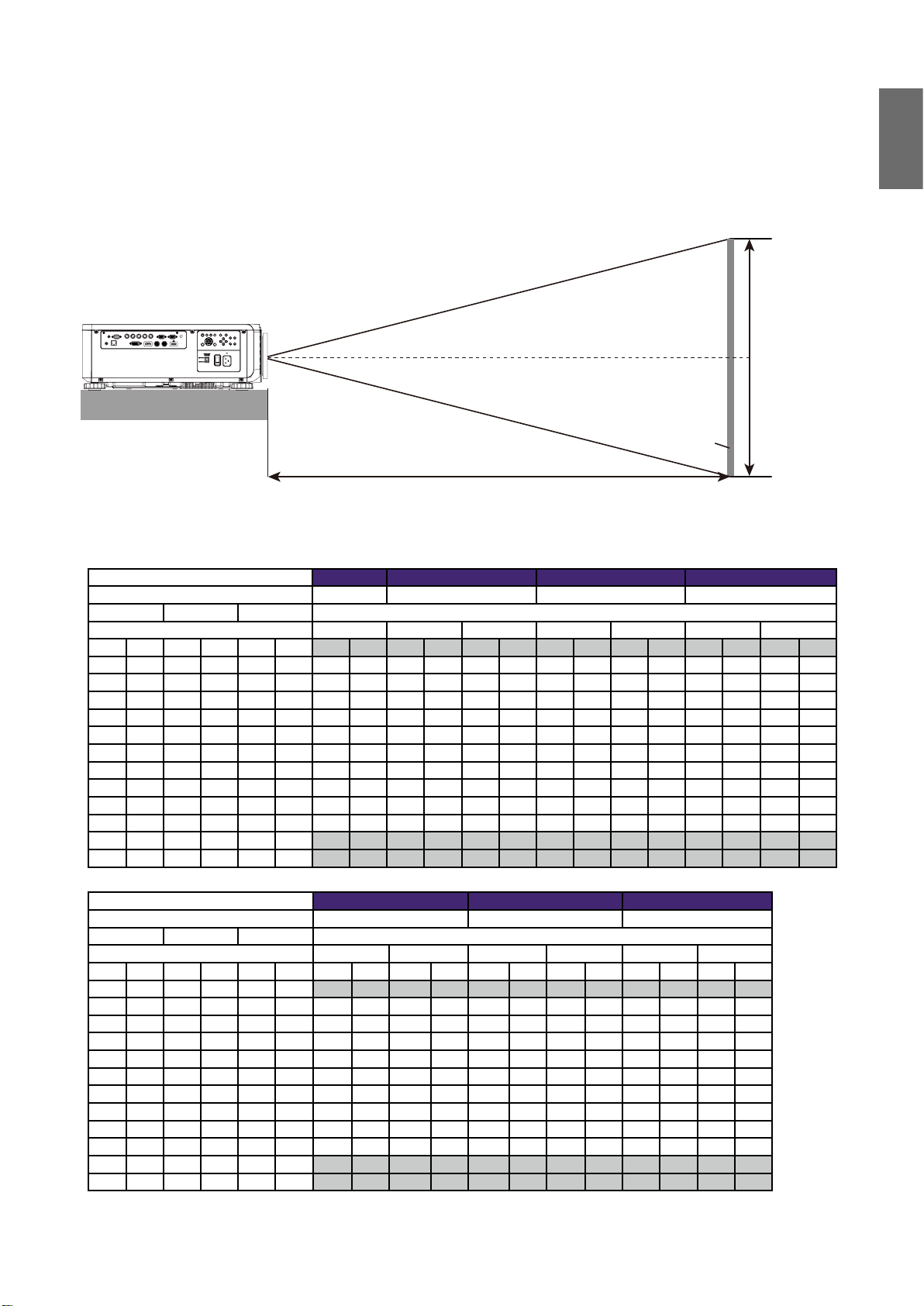
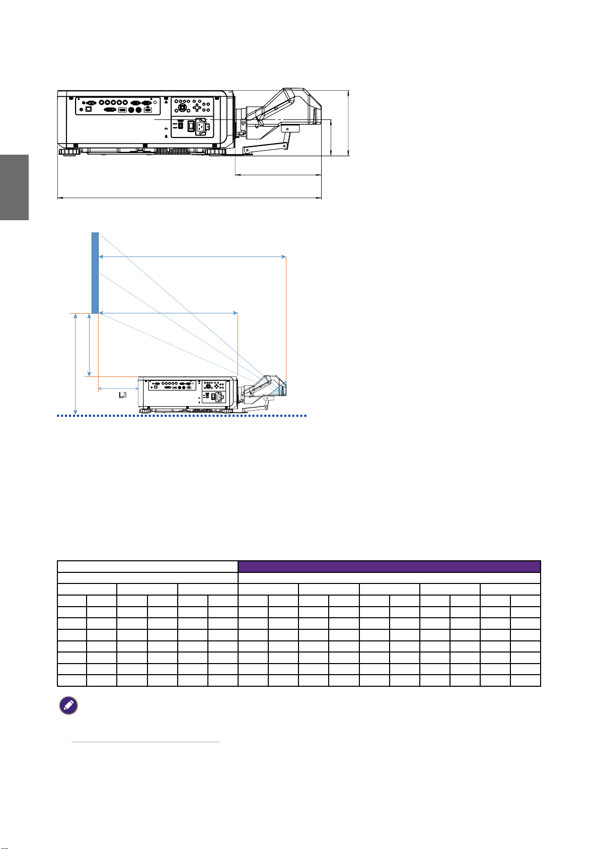
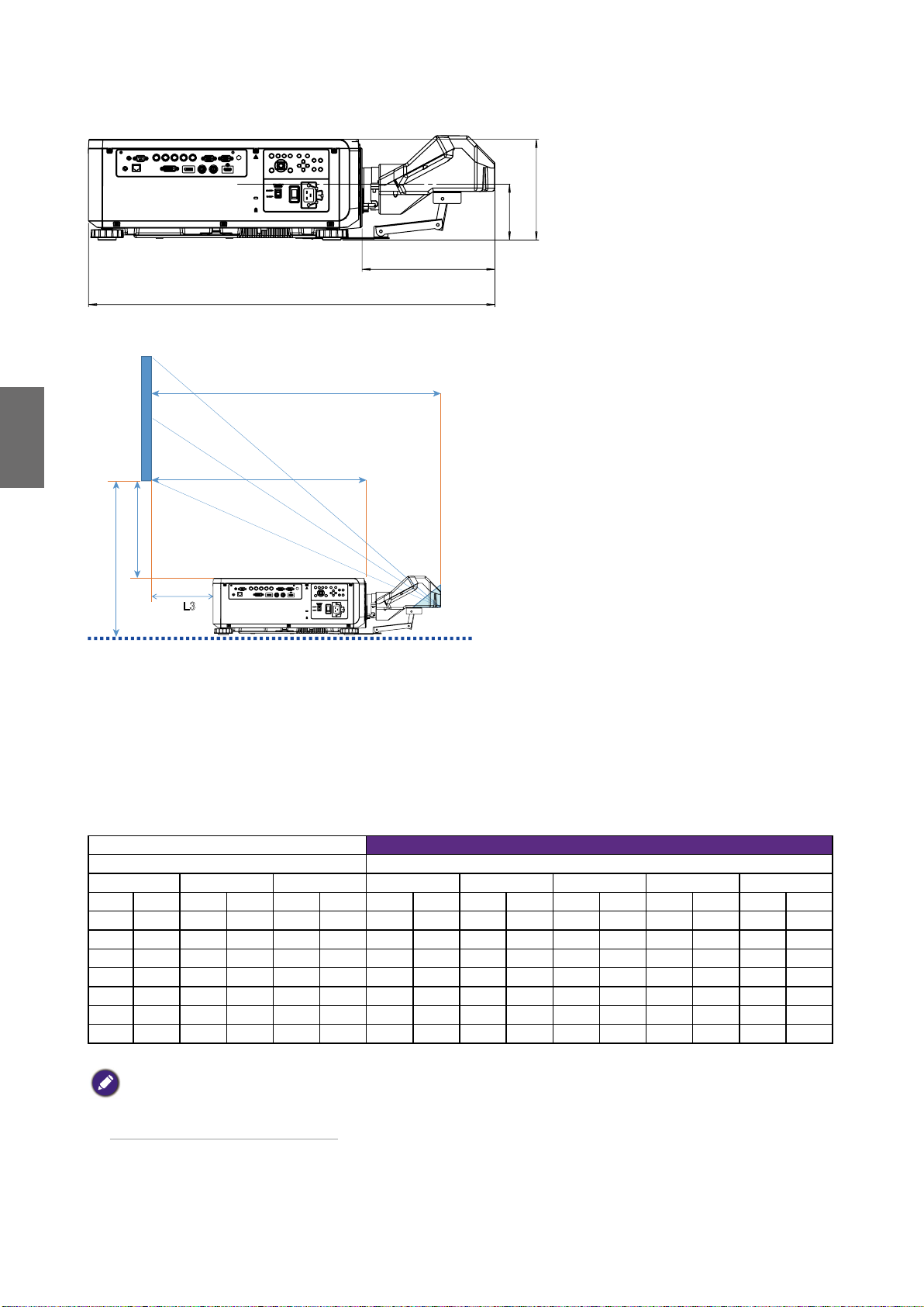
English
Ultra Short Reflection
216
120
285
873
Screen
L1
L2
H1
H2
㻸㻟
L1: Screen to the point of mirror
L2: Screen to projector front
L3: Screen to project back
H1: Screen bottom to projector top side
H2: Screen bottom to projector bottom
Screen size 5J.JCY37.001
Ultra Short Reflection
Diagonal Width Height H1 H2 L1 L2 L3
inch mm inch mm inch mm inch mm inch mm inch mm inch mm inch mm
100 2540 85 2166 53 1355 19 485 28 701 33 849 22 564 -1 -24
120 3048 102 2599 64 1627 23 596 32 812 39 1000 28 715 5 127
150 3810 128 3247 80 2032 30 763 39 979 48 1227 37 942 14 354
200 5080 170 4330 107 2711 41 1041 49 1257 63 1606 52 1321 29 733
250 6350 213 5415 133 3391 52 1320 60 1536 78 1984 67 1699 44 1111
300 7620 256 6500 160 4071 63 1598 71 1814 93 2362 82 2077 59 1489
350 8890 299 7585 187 4752 74 1877 82 2093 108 2741 97 2456 74 1868
Note:
• For more visualized instructions, please go to BenQ calculator website http://projectorcalculator.benq.com/.
• Precise installation is prefered to be done by professionals. Contact your dealer for more information.
• When UST lens is installed to the projector, it is recommended to loosen the screw on the support kit and make
the arm movable before adjustment.
• The User Manual for UST Lens installation is available from local BenQ website.
10
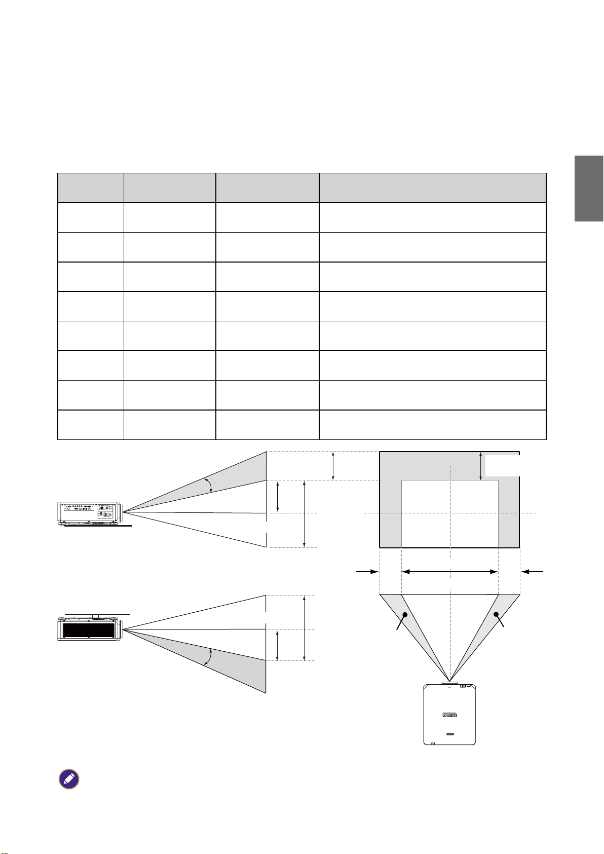
Lens shift
Lens shift adjustable range
The adjustable range for lens shift is tabulated below and subject to the conditions listed.
Model Name Lens Type BenQ Part Number Lens Shift Range
English
LS1ST4 Ultra Short Throw 5J.JCY37.001
-3% ~ +7% Vertical; -5% ~ +5% Horizontal
(Central position at 56.5%)
LS1ST3 Wide fix 5J.JAM37.011 NA
LS1ST2 Ultra Wide 5J.JAM37.061 0 ~ +50% Vertical; -6.7% ~ +6.7% Horizontal
LS1ST1 Wide Zoom 5J.JAM37.021 0 ~ +50% Vertical; -10% ~ +10% Horizontal
LS1SD Standard 5J.JAM37.001 0 ~ +50% Vertical; -10% ~ +10% Horizontal
LS1LT1 Semi Long 5J.JAM37.051 0 ~ +50% Vertical; -10% ~ +10% Horizontal
LS1LT2 Long Zoom1 5J.JAM37.031 0 ~ +50% Vertical; -10% ~ +10% Horizontal
LS1LT3 Long Zoom2 5J.JAM37.041 0 ~ +50% Vertical; -10% ~ +10% Horizontal
Desktop-front projection
Vertical Shift area
Vertical Shift
Max
0.5V
Height of projected image
Ceiling mount-front projection
Height of projected image
Vertical Shift
Note:
The drawings above apply to the standard lens only.
Max
0.5V
1V
1V
0.1H
Horizontal Shift
to Left
1H
Width of projected image
0.1H
Horizontal Shift
to Right
11
English
CX
0.1H
0.1H
C
Installation positioning
Ceiling mount installation
Screen Top
Shift Range
Desktop installation
Shift Range
Screen Center
Screen Center
H
H
C
Note:
• Lens Shift function is not available to LS1ST3 (Fixed Lens). This lens should be used for "zero degree"/"no-offset"
applications. See below:
117.4
FOR USE WITH LS1ST3 (FIXED LENS) ONLY
12
Screen Center
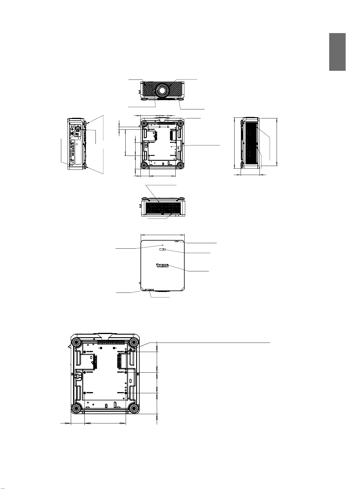
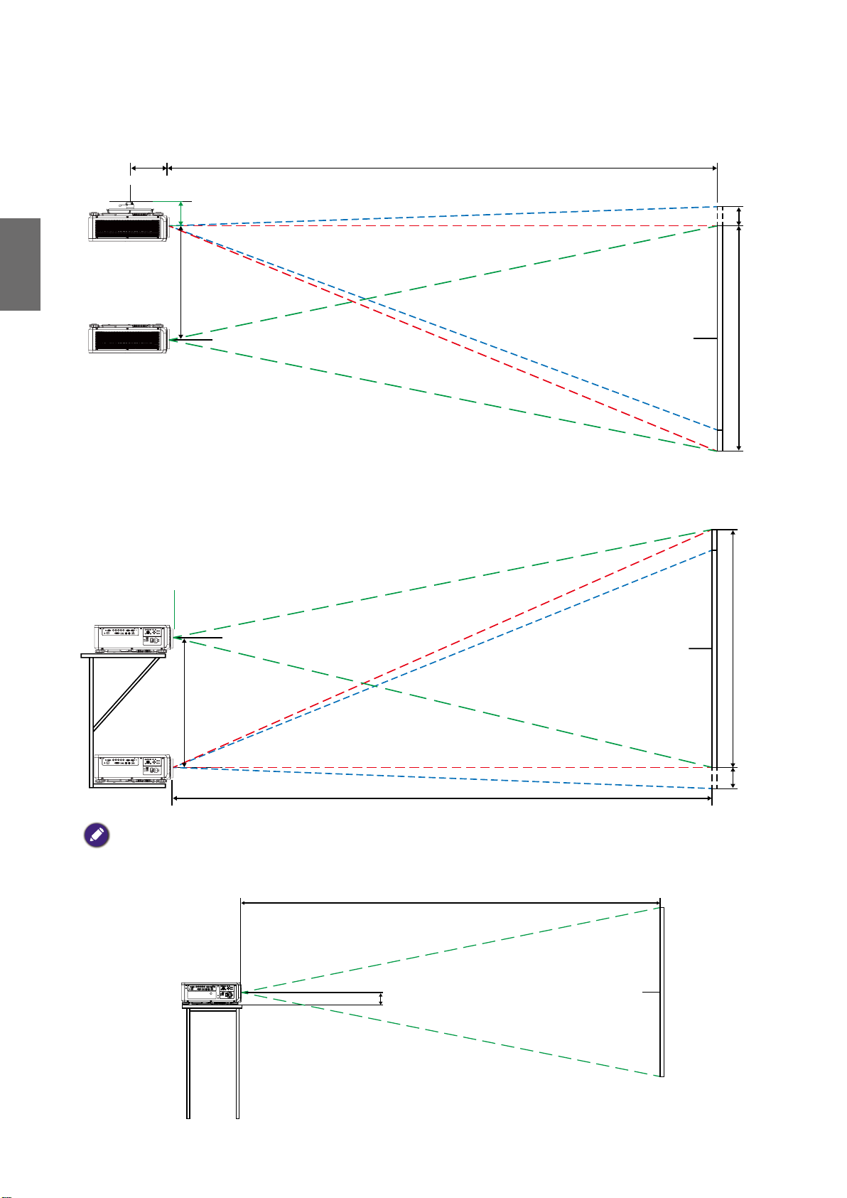
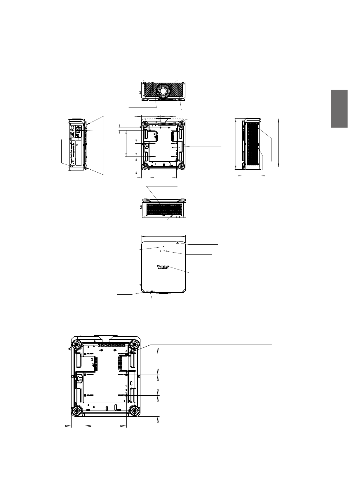
Dimensions
152.5
Cabinet dimensions
English
AIR IN
RELEASE BUTTON
95
220
28
ADJ. FOOT
AC IN
R SIDE COVER
ADJ. FOOT
300
TOP COVER
150
152.50
100
300
REAR COVER
AIR OUT
500
FRONT RING
FRONT COVER
AIR IN
BASE COVER
REAR IR WINDOW
MODEL LOGO
582.80
216
547.26
L SIDE COVER
AIR IN
FRONT IR
LED STATUS
Ceiling mount hole dimensions
6-CEILING MOUNT HOLE
M4*0.7 SCREW L=16 mm (MAX.)
150
150
100
300
NAME PLATE
Unit: mm
13
English
302.5
582.8
633.50
648.50
150
150
300
300
483.60
710.70
483.60
498.60
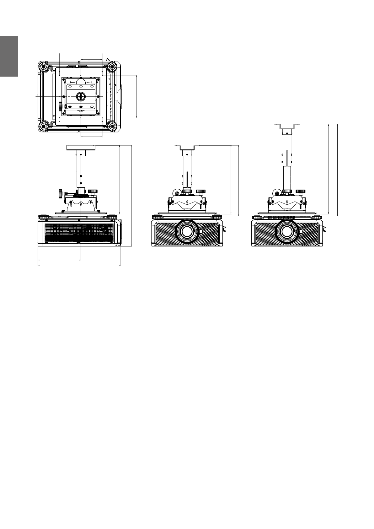
Ceiling mount dimensions (CMG6)
14
Optional lens dimensions
Optional Lens (UST: LSIST4) Optional Lens (WIDE FIX: LSIST3)
500
UST LENS
WIDE FIX LENS
English
582.80
872.5
Optional Lens (UWZ: LSIST2)
UWZ LENS
582.80
639.4
Optional Lens (STD: LSISD)
582.80
610.16
Optional Lens (WIDE: LSIST1)
WIDE LENS
582.8
616.5
Optional Lens (SEMI: LSILT1)
STD LENS
582.80
590.7
Optional Lens (LONG1: LSILT2)
LONG 1 LENS
582.80
626.7
SEMI LONG LENS
582.80
609.90
Optional Lens (LONG2: LSILT3)
LONG2 LENS
582.80
667.3
15
English
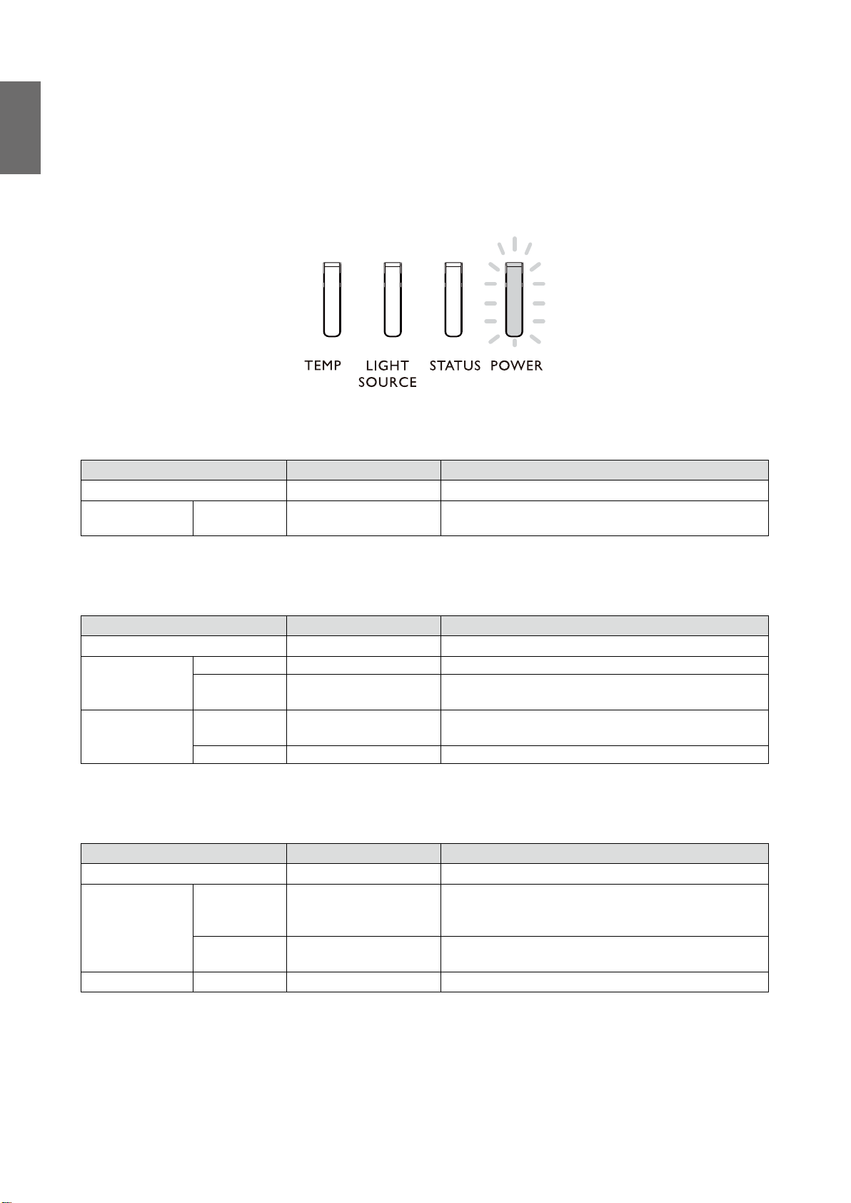
LED indication
Indicator messages
Several indicator messages are used by the projector to alert users about problems with setup or
system error. The LEDs on top cover of the projector illustrated below.
TEMP LED
LED display Projector status Operation tips
Off Normal status
Flashing Red Over temperature error
Contact with your nearest authorized dealer or service
center.
LIGHT SOURCE LED
LED display Projector status Operation tips
Off Light source is off
Green Projector is turning on
Flashing
On
Red (Cycles of
6)
Red Light source problem Please call the local service center.
Green Light source is on
Light source is end-of-life Please call the local service center.
STATUS LED indicator
LED display Projector status Operation tips
Close Normal
Please check whether the top cover is well assembled
Red (once) Safety switch error
Flashing
Red
(quadruple)
Lights up Red System error Call the local service center.
Fan error Call the local service center.
or lens is well installed or not. If the problem persists,
call the local service center.
16

POWER LED indicator
LED display Projector status Operation tips
Close AC power turned off Check AC power source and power on the projector.
Ready to power on the
projector
The projector is cooling
down
Wait until the projector starts projecting.
To power on the projector, press the ON key on the
remote controller or the Power key on the control
panel.
Flashing
Lights up
Green
Orange
Red Standby mode
Green Projector powered on
English
17

Français
Table des matières
Avis ......................................................................................................... 19
Illustration de la ventilation .........................................................................................19
Exigences pour la sortie de la ventilation ...................................................................19
Commutateur de tension ............................................................................................20
Attention lors de l'installation .....................................................................................20
Informations sur le produit .................................................................. 21
Contenu du colis ...........................................................................................................21
Caractéristiques du projecteur ...................................................................................21
Prises ..............................................................................................................................22
Télécommande .............................................................................................................23
Paramètre d’ID de la télécommande .........................................................................23
Installation ............................................................................................. 24
Caractéristiques de l’objectif .......................................................................................24
Table de projection .......................................................................................................25
Décalage de l’objectif ...................................................................................................27
Positionnement de l’installation ..................................................................................28
Dimensions ............................................................................................ 29
Dimensions du boîtier ..................................................................................................29
Dimension des trous de montage au plafond ............................................................29
Dimension de montage au plafond (CMG6) ..............................................................30
Dimensions de l’objectif en option ..............................................................................31
Indication de la diode ............................................................................ 32
Veuillez visiter le site Web ci-dessous la dernière version du Manuel d’utilisation /
Guide d’installation.
http://business-display.benq.com/
10/12/18
18
Avis
Illustration de la ventilation
Entrée d’air
Entrée d’air
Français
Sortie d’air
Exigences pour la sortie de la ventilation
Pour une bonne ventilation du projecteur, veillez à laisser un peu d'espace autour du projecteur,
comme indiqué dans l'illustration ci-dessous :
11,8 pouce/30 cm
ou plus
19,7 pouce/50 cm
ou plus
HDBaseT / LAN
3D Sync Out
RGB IN
RS-232 USBTRIGGER
CENTER
AUTO
POWER
SHUTTER
LENS
INPUT
DVI-D
Display Port
HDMI
R/Pr G/Y B/Pb
HV
RGB OUT
WIRE
MENU EXIT
SYNC ASPECT
LENS
SHIFT
FOCUS
ZOOM
11,8 pouce/30 cm
ou plus
19,7 pouce/50 cm
ou plus
19
Minimum
11,8 pouce/30 cm
Français
Minimum
19,7 pouce/50 cm
RS-232 USBTRIGGER
Display PortDVI-D
WIRE
R/Pr G/YB/Pb
RGB IN
HV
RGB OUT
HDMI
HDBaseT / LAN
3D Sync Out
MENU EXIT
SHIFT
LENS
FOCUS
ZOOM
INPUT
SYNC ASPECT
LENS
SHUTTER
POWER
AUTO
CENTER
39,3 pouce/100 cm
Commutateur de tension
Veuillez vous assurer que le commutateur de tension est réglé sur la bonne tension dans la région
où le projecteur est utilisé.
Remarque :
Le réglage par défaut est de 230 V.
Minimum
Attention lors de l'installation
• Veuillez éteindre le projecteur lorsque vous changez ou retirez l’objectif, ou le projecteur
s’éteindra immédiatement, sans procédure normale.
• Pour éviter d'endommager les puces DLP, ne dirigez jamais un faisceau laser de forte puissance
dans l'objectif de projection.
20
Informations sur le produit
MENU
EXIT
ENTER
1
4
7089
635
2
Contenu du colis
Déballez le colis avec précaution et vérifiez que vous avez les éléments ci-dessous. Certains des
éléments peuvent ne pas être disponibles selon la région de votre achat. Veuillez confirmer avec
votre revendeur.
Français
Projecteur
sans objectif
Câble VGA
Télécommande
sans piles AA/LR06
Câble de télécom-
mande câblée
Guide d’installation
Vis antivol
Caractéristiques du projecteur
Caractéristiques LU9915
Système de projection Puce unique DMD WUXGA 0,67" DLP
Résolution native WUXGA (1920 x 1200)
Luminosité 10.000 Lumens
Câble d’alimentation
Couvercle du trou
de l’objectif
Format 16:10
Source lumineuse Source lumineuse laser
Consommation 1290W à 100V, 1215W à 240V
Dimensions 583 mm (Lo) x 500 mm (La) x 211 mm (H)
Poids 28 kg / 61,7 lb (sans l’objectif)
Température de
32ºF à 104ºF (0ºC à 40ºC)
fonctionnement
Remarque :
• La luminosité est fournie par l’objectif standard. La valeur varie en fonction de l’objectif installé.
• La sortie de luminosité varie en fonction de chaque unité et de l’utilisation réelle.
• Visitez le site Web de http://www.benq.com pour le dernier manuel d’utilisation.
21
Prises
Français
TRIGGER
WIRED
REMOTE HDBaseT/LANDVI-D DISPLAYPORT
RS-232TRIGGER
COMPUTER 2
MONITOR OUTCOMPUTER 1
R/PrG/YB/PbHV
3G-SDI
IN
OUT HDMI
3D SYNC OUT
3D SYNC IN
• HDBaseT/LAN
Pour la connexion à un câble Ethernet RJ45 Cat5/Cat6 pour entrer des signaux de commande
vidéo haute définition (HD) sans compression.
• 3D Sync Out
Connexion au transmetteur de signal de synchronisation infrarouge 3D.
• 3D Sync In
Connexion à l’entrée de signal de synchronisation 3D.
• DVI-D
Connexion à la source DVI-D.
• HDMI
Connexion à la source HDMI.
• DisplayPort
Connexion à l’appareil ou au PC avec fonction DisplayPort.
• 3G-SDI
Connexion à la source 3G-SDI.
• Computer 1
Port VGA à 15 broches pour une connexion à RVB, source composantes HD ou PC.
• Computer 2 (V, H, B/Pb, G/Y, R/Pr)
Connexion à un signal de sortie RVB ou YPbPr/YCbCr avec prise d’entrée de type BNC.
• Monitor Out
Connexion à un autre appareil d’affichage pour un affichage simultané.
• RS-232
Interface D-Sub à 9 broches standard pour la connexion au système de contrôle du PC et la
maintenance du projecteur.
• TRIGGER
Prise casque mini 3,5 mm. Utilise un relais d’affichage 350 mA pour fournir une sortie 12 V
(+/-1,5 V) et une protection de court-circuit.
• Wired Remote
Connexion pour l’entrée de système de répétition infrarouge compatible Niles ou Xantech.
Remarque :
Assurez-vous que le port est valide avant d’insérer une télécommande filaire. La télécommande peut être
endommagée en cas de port non valide, par exemple si une télécommande filaire est connectée à une sortie
déclencheur.
22
Télécommande
ON OFF
ZOOM +/-
FOCUS +/-
Haut
Gauche
MENU
AUTO PC
COMPUTER 1
COMPUTER 2
HDMI 1
3G-SDI
DisplayPort
CLEAR
Boutons numériques
MENU
1
4
7
ENTER
EXIT
3
2
6
5
89
0
TEST PATTERN
Français
LENS-SHIFT
ENTER
Droite
Bas
EXIT
BLANK
STATUS
ASPECT
DVI
HDMI 2
HDBaseT
ID SET
FREEZE
Paramètre d’ID de la télécommande
Vous pouvez configurer l’ID de la télécommande pour contrôler le projecteur spécifique.
Veuillez définir l’ID du projecteur (de 01 à 99) en utilisant les menus OSD. Après avoir configuré
un ID, la télécommande ne contrôlera que le projecteur correspondant.
Appuyez sur les touches ID SET + MENU pendant 5 secondes, le rétroéclairage de la
télécommande clignotera une fois, puis vous passerez en mode Param. ID.
Encore une fois, cliquez sur les touches ID SET + MENU pendant 5 secondes (le rétroéclairage
clignotera 1 fois) pour quitter le mode Param. ID.
Après l’accès au mode Param. ID, appuyez la touche ID SET pendant 3 secondes.
Le voyant à diode de la télécommande clignotera et le rétroéclairage s’allumera. En attendant,
appuyez sur le numéro pour définir l’ID de la télécommande.
Par exemple, pour définir l’ID de la télécommande sur « 01 », appuyez la touche 0 pendant
1 seconde (le voyant à diode clignotera 3 fois puis le rétroéclairage s’éteindra), puis appuyez la
touche 1 pendant 1 seconde (le voyant à diode clignotera 3 fois puis le rétroéclairage s’éteindra).
Pour définir l’ID de la télécommande sur « 19 », appuyez la touche 1 pendant 1 seconde, puis
appuyez la touche 9 pendant 1 seconde.
23
Installation
Caractéristiques de l’objectif
Français
Nom de
modèle
LS1ST4
LS1ST3 Fixe large 5J.JAM37.011 F=1.85, f=11,6mm 0,76:1 Fixe 910g
LS1ST2 Ultra large 5J.JAM37.061
LS1ST1 Zoom large 5J.JAM37.021
LS1SD Standard 5J.JAM37.001
LS1LT1 Semi long 5J.JAM37.051
LS1LT2 Zoom long 1 5J.JAM37.031
LS1LT3 Zoom long 2 5J.JAM37.041
Type
d'objectif
Projection
ultra courte
Référence
BenQ
5J.JCY37.002 F=2.0, f=5,64 mm 0,38:1 Fixe 2.710g
Caractéristiques
optiques
F=1,96~2,3,
f=11,3~14,1mm
F=1,85~2,5,
f=18,7~26,5mm
F=1,7~1,9,
f=26~34mm
F=1,86~2,48,
f=32,9~54,2mm
F=1,85~2,41,
f=52,8~79,1mm
F=1,85~2,48,
f=78,5~121,9mm
Rapport de
projection
0,75~0,93:1 1,25:1 1.280g
1,25~1,79:1 1,41:1 1.090g
1,73~2,27:1 1,3:1 820g
2,22~3,67:1 1,65:1 950g
3,58~5,38:1 1,5:1 1.020g
5,31~8,26:1 1,55:1 1.350g
Rapport de
zoom
Remarque :
Poids*
Les valeurs listées dans le tableau ci-dessus sont des moyennes et peuvent varier selon le modèle.
24
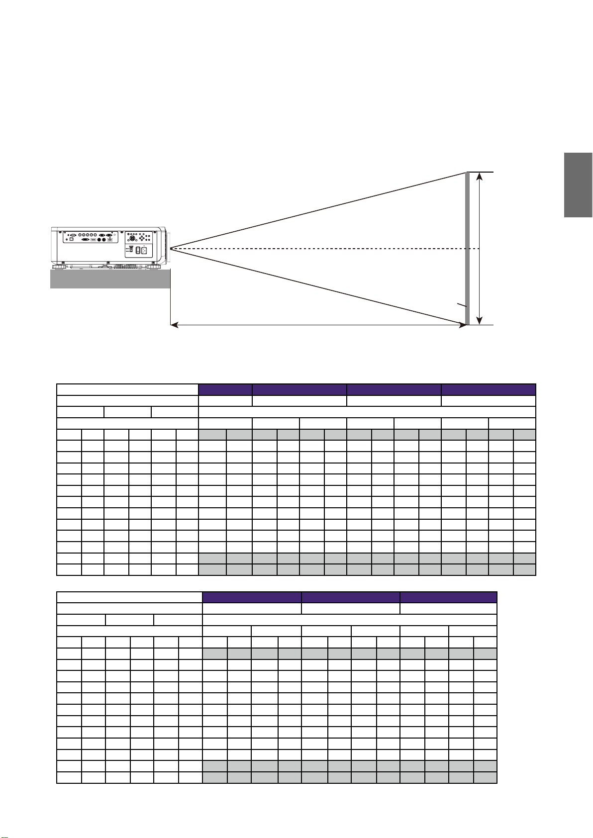
Table de projection
Objectif fixe large, objectif à zoom large, objectif STD, zoom
semi long 1, objectif zoom long 1, objectif zoom long 2, objectif
zoom ultra large
Centre de
l’objectif
ÉCRAN
Distance (A)
LU9915
Taille d’écran 5J.JAM37.011 5J.JAM37.021 5J.JAM37.001 5J.JAM37.051
Objectif fixe large Objectif à zoom large Objectif STD Zoom semi long 1
Diagonale Largeur Hauteur (B) Distance (A)
Fixe Large Télé Large Télé Large Télé
(pouce) (m) (pouce) (m) (pouce) (m) (pouce) (m) (pouce) (m) (pouce) (m) (pouce) (m) (pouce) (m) (pouce) (m) (pouce) (m)
40 1,02 34 0,86 21 0,54 25,1 0,64 41,4 1,05 59,9 1,52 57,2 1,45 75,8 1,93 73,6 1,87 124,1 3,15
50 1,27 42 1,08 26 0,67 31,8 0,81 52,3 1,33 75,4 1,92 72,1 1,83 95,5 2,42 92,9 2,36 155,9 3,96
60 1,52 51 1,29 32 0,81 38,5 0,98 63,1 1,60 90,9 2,31 87,1 2,21 115,1 2,92 112,1 2,85 187,8 4,77
80 2,03 68 1,72 42 1,08 52,0 1,32 84,9 2,16 121,8 3,09 117,0 2,97 154,3 3,92 150,5 3,82 251,4 6,39
100 2,54 85 2,15 53 1,35 65,5 1,66 106,6 2,71 152,7 3,88 147,0 3,73 193,5 4,92 188,9 4,80 315,0 8,00
120 3,05 102 2,58 64 1,62 78,9 2,01 128,4 3,26 183,6 4,66 176,9 4,49 232,8 5,91 227,6 5,78 378,6 9,62
150 3,81 127 3,23 79 2,02 99,1 2,52 161,0 4,09 230,0 5,84 221,8 5,63 291,6 7,41 285,0 7,24 474,1 12,04
180 4,57 153 3,88 95 2,42 119,3 3,03 193,6 4,92 276,4 7,02 266,7 6,77 350,5 8,90 342,6 8,70 569,5 14,47
200 5,08 170 4,31 106 2,69 132,8 3,37 215,3 5,47 307,3 7,81 296,6 7,53 389,7 9,90 381,0 9,68 633,1 16,08
300 7,62 254 6,46 159 4,04 200,1 5,08 324,0 8,23 461,9 11,73 446,3 11,34 585,9 14,9 573,2 14,56 951,2 24,16
400 10,16 339 8,62 212 5,38 267,4 6,79 432,7 10,99 616,6 15,66 595,9 15,14 782,3 19,87 765,3 19,44 1269,7 32,25
500 12,70 424 10,77 265 6,73 334,8 8,50 541,5 13,75 771,2 19,59 745,6 18,94 978,3 24,85 957,4 24,32 1587,8 40,33
Hauteur (B)
Français
Taille d’écran 5J.JAM37.031 5J.JAM37.041 5J.JAM37.061
Objectif zoom long 1 Objectif zoom long 2 Objectif zoom ultra large
Diagonale Largeur Hauteur (B) Distance (A)
Large Télé Large Télé Large Télé
(pouce) (m) (pouce) (m) (pouce) (m) (pouce) (m) (pouce) (m) (pouce) (m) (pouce) (m) (pouce) (m) (pouce) (m)
40 1,02 34 0,86 21 0,54 118,7 3,01 181,0 4,60 173,9 4,42 277,7 7,05 24,5 0,62 31,1 0,79
50 1,27 42 1,08 26 0,67 149,7 3,80 227,6 5,78 220,2 5,59 350,0 8,89 31,1 0,79 39,2 1,00
60 1,52 51 1,29 32 0,81 180,7 4,59 274,1 6,96 266,6 6,77 422,3 10,73 37,6 0,96 47,4 1,20
80 2,03 68 1,72 42 1,08 242,7 6,16 367,3 9,33 359,4 9,13 567,0 14,40 50,8 1,29 63,8 1,62
100 2,54 85 2,15 53 1,35 304,3 7,73 460,4 11,70 452,1 11,48 711,6 18,07 63,9 1,62 80,2 2,04
120 3,05 102 2,58 64 1,62 366,7 9,31 553,6 14,06 544,9 13,84 856,2 21,75 77,1 1,96 96,6 2,45
150 3,81 127 3,23 79 2,02 459,4 11,67 693,3 17,61 684,0 17,37 1073,1 27,26 96,8 2,46 121,1 3,08
180 4,57 153 3,88 95 2,42 552,4 14,03 833,0 21,16 823,1 20,91 1290,1 32,77 116,5 2,96 145,7 3,70
200 5,08 170 4,31 106 2,69 614,7 15,6 926,4 23,53 915,9 23,26 1434,7 36,44 129,7 3,29 162,1 4,12
300 7,62 254 6,46 159 4,04 924,0 23,47 1392,1 35,36 1379,6 35,04 2157,8 54,81 195,4 4,96 244,0 6,20
400 10,16 339 8,62 212 5,38 1233,9 31,34 1857,9 47,19 1843,3 46,82 2880,9 73,18 261,2 6,63 325,9 8,28
500 12,70 424 10,77 265 6,73 1543,7 39,21 2323,6 59,02 2307,1 58,60 3604,0 91,54 326,9 8,30 407,7 10,36
25
Réflexion ultra courte
216
120
Français
285
873
Écran
L1
L2
H1
H2
㻸㻟
L1 : Écran au point du miroir
L2 : Écran à l’avant du projecteur
L3 : Écran à l’arrière du projecteur
H1 : Bas de l’écran au dessus du projecteur
H2 : Bas de l’écran au dessous du projecteur
Taille d’écran 5J.JCY37.001
Réflexion ultra courte
Diagonale Largeur Hauteur H1 H2 L1 L2 L3
pouce mm pouce mm pouce mm pouce mm pouce mm pouce mm pouce mm pouce mm
100 2540 85 2166 53 1355 19 485 28 701 33 849 22 564 -1 -24
120 3048 102 2599 64 1627 23 596 32 812 39 1000 28 715 5 127
150 3810 128 3247 80 2032 30 763 39 979 48 1227 37 942 14 354
200 5080 170 4330 107 2711 41 1041 49 1257 63 1606 52 1321 29 733
250 6350 213 5415 133 3391 52 1320 60 1536 78 1984 67 1699 44 1111
300 7620 256 6500 160 4071 63 1598 71 1814 93 2362 82 2077 59 1489
350 8890 299 7585 187 4752 74 1877 82 2093 108 2741 97 2456 74 1868
Remarque :
• Pour des instructions plus visualisées, veuillez visiter le site Web de la calculatrice BenQ
http://projectorcalculator.benq.com/.
• Une installation précise est préférablement effectuée par des professionnels. Contactez votre revendeur pour plus
d’informations.
• Quand l’objectif UST est installé sur le projecteur, il est recommandé de desserrer la vis du kit de support et de
rendre le bras mobile avant l’ajustement.
• Le manuel d’utilisation pour l’installation de l’objectif UST est disponible sur le site Web BenQ local.
26
Décalage de l’objectif
Plage ajustable du décalage de l’objectif
La plage ajustable de décalage de l’objectif est présentée ci-dessous et sous réserve des conditions
listées.
Français
Nom de
modèle
LS1ST4
Type d'objectif Référence BenQ Plage du décalage de l’objectif
Projection ultra
courte
5J.JCY37.001
-3% ~ +7% vertical ; -5% ~ +5% horizontal
(position centrale à 56,5%)
LS1ST3 Fixe large 5J.JAM37.011 ND
LS1ST2 Ultra large 5J.JAM37.061 0 ~ +50% vertical ; -6,7% ~ +6,7% horizontal
LS1ST1 Zoom large 5J.JAM37.021 0 ~ +50% vertical ; -10% ~ +10% horizontal
LS1SD Standard 5J.JAM37.001 0 ~ +50% vertical ; -10% ~ +10% horizontal
LS1LT1 Semi long 5J.JAM37.051 0 ~ +50% vertical ; -10% ~ +10% horizontal
LS1LT2 Zoom long 1 5J.JAM37.031 0 ~ +50% vertical ; -10% ~ +10% horizontal
LS1LT3 Zoom long 2 5J.JAM37.041 0 ~ +50% vertical ; -10% ~ +10% horizontal
Projection avant, bureau
Décalage
vertical
Max
0,5V
Zone de
décalage vertical
Hauteur de l’image projetée
1V
Projection avant, montée
au plafond
Hauteur de l’image projetée
Décalage
vertical
Remarque :
Les dessins ci-dessus s’appliquent à l’objectif standard seulement.
1V
Max
0,5V
0,1 H
Décalage horizontal
à gauche
1 H
Largeur de l’image projetée
0,1 H
Décalage horizontal
à droite
27
Positionnement de l’installation
CX
0.1H
0.1H
C
Configuration de montage au plafond
Français
Plage du décalage
Installation sur bureau
Haut écran
Centre de l’écran
H
Centre de l’écran
Plage du décalage
C
Remarque :
• La fonction de décalage de l’objectif n’est pas disponible pour le LS1ST3 (objectif fixe). Cet objectif devrait être
utilisé pour les applications « degré zéro »/« sans décalage ». Voir ci-dessous :
117.4
Centre de l’écran
H
POUR UTILISATION AVEC LS1ST3 (OBJECTIF FIXE) SEULEMENT
28
Dimensions
152.5
Dimensions du boîtier
AIR IN
FRONT RING
Français
RELEASE BUTTON
95
220
28
ADJ. FOOT
AC IN
R SIDE COVER
ADJ. FOOT
300
TOP COVER
150
152.50
100
300
REAR COVER
AIR OUT
500
FRONT COVER
AIR IN
BASE COVER
REAR IR WINDOW
MODEL LOGO
582.80
216
547.26
L SIDE COVER
AIR IN
NAME PLATE
FRONT IR
LED STATUS
Dimension des trous de montage au plafond
6-CEILING MOUNT HOLE
M4*0.7 SCREW L=16 mm (MAX.)
150
150
100
300
Unit: mm
29

Français
302.5
582.8
633.50
648.50
150
150
300
300
483.60
710.70
483.60
498.60
Dimension de montage au plafond (CMG6)
30

Dimensions de l’objectif en option
Objectif en option (FIXE LARGE :
Objectif en option (UST : LSIST4)
LSIST3)
500
582.80
872.5
Objectif en option (UWZ : LSIST2)
UWZ LENS
582.80
639.4
Français
UST LENS
WIDE FIX LENS
582.80
610.16
Objectif en option (LARGE : LSIST1)
WIDE LENS
582.8
616.5
Objectif en option (STD : LSISD)
STD LENS
582.80
590.7
Objectif en option (LONG1 : LSILT2)
LONG 1 LENS
Objectif en option (SEMI : LSILT1)
SEMI LONG LENS
582.80
609.90
Objectif en option (LONG2 : LSILT3)
LONG2 LENS
582.80
626.7
582.80
667.3
31

Français
Indication de la diode
Messages des voyants
Plusieurs messages des voyants sont utilisés par le projecteur pour alerter les utilisateurs sur les
problèmes avec la configuration ou une erreur système. Les diodes sur le couvercle supérieur du
projecteur sont illustrées ci-dessous.
Diode TEMP
Affichage de la diode Statut du projecteur Conseils de fonctionnement
Éteinte Statut normal
Clignotante Rouge Erreur de surchauffe
Contactez votre revendeur agréé le plus proche ou le
centre de service.
Diode LIGHT SOURCE (SOURCE LUMINEUSE)
Affichage de la diode Statut du projecteur Conseils de fonctionnement
Éteinte
Clignotante
Allumée
Vert Le projecteur s’allume
Rouge (cycles
de 6)
Rouge
Vert
La source lumineuse est
éteinte
La source lumineuse est
proche de la fin de vie
Problème de la source
lumineuse
La source lumineuse est
allumée
Veuillez appeler le centre de service local.
Veuillez appeler le centre de service local.
Voyant à diode STATUS (STATUT)
Affichage de la diode Statut du projecteur Conseils de fonctionnement
Éteinte Normal
Rouge (une
Clignotante
Allumée Rouge Erreur système Appelez le centre de service local.
fois)
Rouge
(quatre fois)
Erreur du commutateur
de sécurité
Erreur de ventilateur Appelez le centre de service local.
Veuillez vérifier si le couvercle supérieur est bien
assemblé ou si l’objectif est bien installé ou non. Si le
problème continue, appelez le centre de service local.
32

Voyant à diode POWER (ALIMENTATION)
Affichage de la diode Statut du projecteur Conseils de fonctionnement
Éteinte
Clignotante
Allumée
Alimentation du
projecteur éteinte
Vert
Orange
Rouge Mode Veille
Vert Projecteur allumé
Prêt pour allumer le
projecteur
Le projecteur est en
cours de refroidissement
Vérifiez la source d’alimentation secteur et allumez le
projecteur.
Attendez que le projecteur commence la projection.
Pour allumer le projecteur, appuyez la touche ON de
la télécommande ou la touche d’alimentation sur le
panneau de commande.
Français
33

Deutsch
Inhaltsverzeichnis
Hinweis ................................................................................................... 35
Lüftungsabbildung .........................................................................................................35
Anforderungen an die Abluftöffnung ..........................................................................35
Spannungsumschalter ..................................................................................................36
Achtung während der Installation...............................................................................36
Produktinformationen .......................................................................... 37
Lieferumfang .................................................................................................................37
Daten des Projektors ....................................................................................................37
Anschlüsse .....................................................................................................................38
Fernbedienung ..............................................................................................................39
Fernbedienung ID Einstellung .....................................................................................39
Installation ............................................................................................. 40
Objektiv-Spezifikationen ..............................................................................................40
Projektionstabelle .........................................................................................................41
Linsenverschiebung ......................................................................................................43
Installationsposition ......................................................................................................44
Abmessungen ........................................................................................ 45
Gehäuseabmessungen ..................................................................................................45
Abmessungen der Bohrungen für Deckenmontage ..................................................45
Deckenhalterung Abmessung (CMG6) .......................................................................46
Optionale Objektivabmessungen ................................................................................47
LED Anzeige .......................................................................................... 48
Die aktuellste Version des Benutzerhandbuchs / Installationshandbuchs finden Sie auf
der folgenden Webseite.
http://business-display.benq.com/
10/12/18
34

Hinweis
Lüftungsabbildung
Lufteinlass
Lufteinlass
Luftauslass
Anforderungen an die Abluftöffnung
Für eine ausreichende Kühlung des Projektors stellen Sie bitte sicher, dass genügend Abstand um
den Projektor wie unten abgebildet eingehalten wird.
11,8 Zoll/30 cm
oder größer
11,8 Zoll/30 cm
oder größer
Deutsch
19,7 Zoll/50 cm
oder größer
HDBaseT / LAN
3D Sync Out
RGB IN
RS-232 USBTRIGGER
CENTER
AUTO
POWER
SHUTTER
LENS
INPUT
DVI-D
Display Port
HDMI
R/Pr G/Y B/Pb
HV
RGB OUT
WIRE
MENU EXIT
SYNC ASPECT
FOCUS
ZOOM
LENS
SHIFT
19,7 Zoll/50 cm
oder größer
35

Minimum
11,8 Zoll/30 cm
Deutsch
Minimum
19,7 Zoll/50 cm
RS-232 USBTRIGGER
Display PortDVI-D
WIRE
R/Pr G/YB/Pb
RGB IN
HV
RGB OUT
HDMI
HDBaseT / LAN
3D Sync Out
MENU EXIT
SHIFT
LENS
FOCUS
ZOOM
INPUT
SYNC ASPECT
LENS
SHUTTER
POWER
AUTO
CENTER
39,3 Zoll/100 cm
Spannungsumschalter
Bitte stellen Sie sicher, dass der Spannungsschalter auf die richtige Spannung in der Region
eingestellt wird, in welcher der Projektor verwendet wird.
Hinweis:
Standardeinstellung ist 230V.
Minimum
Achtung während der Installation
• Schalten Sie den Projektor vor dem Austauschen oder Einsetzen der Linse aus. Anderenfalls
wird sich der Projektor sofort ohne normales Herunterfahren ausschalten.
• Um eine Beschädigung der DLP-Chips zu vermeiden, richten Sie niemals einen
Hochleistungslaserstrahl in die Projektionslinse.
36
Produktinformationen
MENU
EXIT
ENTER
1
4
7089
635
2
Lieferumfang
Packen Sie den Inhalt vorsichtig aus und prüfen Sie, ob alle der folgenden Teile vorhanden sind.
Einige dieser Teile stehen u. U. je nach Lieferort nicht zur Verfügung. Erkundigen Sie sich am
Kaufort.
Deutsch
Projektor
ohne Objektiv
VGA-Kabel
Fernbedienung
ohne AA Batterien
Kabel für
Kabelfernbedienung
Installationsanleitung
Anti-Diebstahl
Schraube
Daten des Projektors
Technische Daten LU9915
Projektionssystem DLP Einzel 0,67" WUXGA DMD Chip
Native Auflösung WUXGA (1920 x 1200)
Helligkeit 10.000 Lumen
Netzkabel
Schutzkappe für
Objektivöffnung
Bildformat 16:10
Lichtquelle Laser Lichtquelle
Stromverbrauch 1290W@100V, 1215W@240V
Abmessungen 583mm (L) x 500mm (W) x 211mm (H)
Gewicht 28 kg / 61,7 lbs (ohne Objektiv)
Betriebstemperatur 32ºF bis 104ºF (0ºC bis 40ºC)
Hinweis:
• Die Helligkeit wird durch ein Standard-Objektiv geliefert. Der Wert variiert je nach installierten Objektiven.
• Die Helligkeitsausgabe variiert je nach Gerät und Verbrauch.
• Bitte besuchen Sie die lokale Webseite http://www.benq.com für das aktuelle Benutzerhandbuch.
37

Anschlüsse
Deutsch
TRIGGER
WIRED
REMOTE HDBaseT/LANDVI-D DISPLAYPORT
RS-232TRIGGER
COMPUTER 2
MONITOR OUTCOMPUTER 1
R/PrG/YB/PbHV
3G-SDI
IN
OUT HDMI
3D SYNC OUT
3D SYNC IN
• HDBaseT/LAN
Für die Verbindung mit RJ45 Cat5/Cat6 Ethernet-Kabeln für den Eingang von unkomprimierten
High-Definition Video (HD), Steuerungssignale.
• 3D Sync Out
Verbindung mit 3D IR Synchronisierungssignalsender.
• 3D Sync In
Verbindung mit 3D Synchronisierungssignaleingang.
• DVI-D
Verbindung mit DVI-Quelle.
• HDMI
Verbindung mit HDMI-Quelle.
• DisplayPort
Verbindung mit einem Gerät oder PC über DisplayPort.
• 3G-SDI
Verbindung mit 3G-SDI-Quelle.
• Computer 1
15-Pin VGA Port für Verbindung mit RGB, Component HD Quelle oder PC.
• Computer 2 (V, H, B/Pb, G/Y, R/Pr)
Verbindung mit RGB oder YPbPr/YCbCr Ausgangssignal mit BNC Typ Eingangsanschluss.
• Monitor Out
Verbindung mit anderem Monitor für gleichzeitige Wiedergabeanzeige.
• RS-232
Standard 9-Pin D-Sub Schnittstelle für Verbindung mit PC Steuerungssystem und
Projektorwartung.
• TRIGGER
3,5 mm Mini-Kopfhörerbuchse, nutzt 350mA Anzeige-Relais für 12 (+/-1,5) V Ausgang und
Kurzschlussschutz.
• Wired Remote
Verbindung für Eingang von Niles oder Xantech kompatiblen IR Repeater-System.
Hinweis:
Stellen Sie sicher, dass der Port gültig ist, bevor Sie eine Kabel-Fernbedienung anschließen. Die Fernbedienung könnte
im Falle eines ungültigen Ports beschädigt werden, z.B. wenn eine Kabel-Fernbedienung an den Auslöser-Ausgang
angeschlossen wird.
38
Fernbedienung
89
ON OFF
ZOOM +/-
FOCUS +/-
Oben
Links
MENU
AUTO PC
COMPUTER 1
COMPUTER 2
HDMI 1
3G-SDI
DisplayPort
CLEAR
Zifferntasten
MENU
TEST PATTERN
LENS-SHIFT
ENTER
ENTER
EXIT
1
4
7
3
2
6
5
0
Rechts
Unten
EXIT
BLANK
STATUS
ASPECT
DVI
HDMI 2
HDBaseT
ID SET
FREEZE
Deutsch
Fernbedienung ID Einstellung
Sie können die ID der Fernbedienung einstellen, um den Projektor zu steuern.
Stellen Sie die Projektor-ID (von 01 bis 99) mithilfe der OSD-Menüs ein. Nach dem Einrichten
einer anderen ID wird die Fernbedienung nur noch den entsprechenden Projektor steuern.
Drücken Sie die Tasten ID SET + MENU gleichzeitig 5 Sekunden lang, die Hintergrundbeleuchtung
der Fernbedienung blinkt einmalig und wechselt dann in den ID-Einstellungen Modus.
Klicken Sie erneut 5 Sekunden lang auf die ID SET + MENU Tasten (Hintergrundbeleuchtung blinkt
1 mal), um den ID-Einstellungen Modus freizugeben.
Drücken Sie nach dem Einschalten in den ID-Einstellungen Modus die Taste ID SET 3 Sekunden
lang.
Die LED-Leuchte der Fernbedienung blinkt und die Hintergrundbeleuchtung leuchtet. Drücken Sie
in der Zwischenzeit auf eine Zahl, um die ID der Fernbedienung einzustellen.
Zum Beispiel, um die ID der Fernbedienung auf "01" zu stellen, drücken Sie bitte 1 Sekunde lang
die Taste 0 (LED leuchtet dreimal auf, dann erlischt das Licht), dann drücken Sie 1 Sekunde lang
die Taste 1 (LED blinkt 3 mal, dann erlischt die Hintergrundbeleuchtung).
Um die ID der Fernbedienung auf "19" zu stellen, drücken Sie bitte 1 Sekunde lang die Taste 1,
dann drücken Sie 1 Sekunde lang die Taste 9.
39

Installation
Objektiv-Spezifikationen
Deutsch
Modellname Objektivtyp
LS1ST4
LS1ST3 Weitwinkel-Fix 5J.JAM37.011
LS1ST2 Ultraweitwinkel 5J.JAM37.061
LS1ST1 Weitwinkelzoom 5J.JAM37.021
LS1SD Standard 5J.JAM37.001
LS1LT1 Halblang 5J.JAM37.051
LS1LT2 Langer Zoom 1 5J.JAM37.031
LS1LT3 Langer Zoom 2 5J.JAM37.041
Ultrakurzprojektion
BenQ
Artikelnummer
5J.JCY37.002 F=2,0, f=5,64mm 0,38:1 Fest 2.710g
Optische Daten
F=1,85,
f=11,6mm
F=1,96~2,3,
f=11,3~14,1mm
F=1,85~2,5,
f=18,7~26,5mm
F=1,7~1,9,
f=26~34mm
F=1,86~2,48,
f=32,9~54,2mm
F=1,85~2,41,
f=52,8~79,1mm
F=1,85~2,48,
f=78,5~121,9mm
Projektions-
verhältnis
0,76:1 Fest 910g
0,75~0,93:1 1,25:1 1.280g
1,25~1,79:1 1,41:1 1.090g
1,73~2,27:1 1,3:1 820g
2,22~3,67:1 1,65:1 950g
3,58~5,38:1 1,5:1 1.020g
5,31~8,26:1 1,55:1 1.350g
Zoomver-
hältnis
Gewicht*
Hinweis:
Die in der obigen Tabelle angegebenen Werte sind Durchschnittswerte und können je nach Modell variieren.
40

Projektionstabelle
Weitwinkel-Fixobjektiv, Weitwinkel-Zoomobjektiv, STDObjektiv, Halblanges Zoom 1, Langes Zoom 1 Objektiv, Langes
Zoom 2 Objektiv, Ultraweitwinkel-Zoomobjektiv
Objektivmitte
Höhe (B)
LEINWAND
Abstand (A)
LU9915
Leinwandgröße 5J.JAM37.011 5J.JAM37.021 5J.JAM37.001 5J.JAM37.051
Weitwinkel-
Fixobjektiv
Diagonal Breite Höhe (B) Abstand (A)
Fest Weitwinkel Tele Weitwinkel Tele Weitwinkel Tele
(Zoll) (m) (Zoll) (m) (Zoll) (m) (Zoll) (m) (Zoll) (m) (Zoll) (m) (Zoll) (m) (Zoll) (m) (Zoll) (m) (Zoll) (m)
40 1,02 34 0,86 21 0,54 25,1 0,64 41,4 1,05 59,9 1,52 57,2 1,45 75,8 1,93 73,6 1,87 124,1 3,15
50 1,27 42 1,08 26 0,67 31,8 0,81 52,3 1,33 75,4 1,92 72,1 1,83 95,5 2,42 92,9 2,36 155,9 3,96
60 1,52 51 1,29 32 0,81 38,5 0,98 63,1 1,60 90,9 2,31 87,1 2,21 115,1 2,92 112,1 2,85 187,8 4,77
80 2,03 68 1,72 42 1,08 52,0 1,32 84,9 2,16 121,8 3,09 117,0 2,97 154,3 3,92 150,5 3,82 251,4 6,39
100 2,54 85 2,15 53 1,35 65,5 1,66 106,6 2,71 152,7 3,88 147,0 3,73 193,5 4,92 188,9 4,80 315,0 8,00
120 3,05 102 2,58 64 1,62 78,9 2,01 128,4 3,26 183,6 4,66 176,9 4,49 232,8 5,91 227,6 5,78 378,6 9,62
150 3,81 127 3,23 79 2,02 99,1 2,52 161,0 4,09 230,0 5,84 221,8 5,63 291,6 7,41 285,0 7,24 474,1 12,04
180 4,57 153 3,88 95 2,42 119,3 3,03 193,6 4,92 276,4 7,02 266,7 6,77 350,5 8,90 342,6 8,70 569,5 14,47
200 5,08 170 4,31 106 2,69 132,8 3,37 215,3 5,47 307,3 7,81 296,6 7,53 389,7 9,90 381,0 9,68 633,1 16,08
300 7,62 254 6,46 159 4,04 200,1 5,08 324,0 8,23 461,9 11,73 446,3 11,34 585,9 14,9 573,2 14,56 951,2 24,16
400 10,16 339 8,62 212 5,38 267,4 6,79 432,7 10,99 616,6 15,66 595,9 15,14 782,3 19,87 765,3 19,44 1269,7 32,25
500 12,70 424 10,77 265 6,73 334,8 8,50 541,5 13,75 771,2 19,59 745,6 18,94 978,3 24,85 957,4 24,32 1587,8 40,33
Weitwinkel-Zoomobjektiv STD-Objektiv Halblanges Zoom 1
Deutsch
Leinwandgröße 5J.JAM37.031 5J.JAM37.041 5J.JAM37.061
Langes Zoom 1 Objektiv Langes Zoom 2 Objektiv Ultraweitwinkel-Zoomobjektiv
Diagonal Breite Höhe (B) Abstand (A)
Weitwinkel Tele Weitwinkel Tele Weitwinkel Tele
(Zoll) (m) (Zoll) (m) (Zoll) (m) (Zoll) (m) (Zoll) (m) (Zoll) (m) (Zoll) (m) (Zoll) (m) (Zoll) (m)
40 1,02 34 0,86 21 0,54 118,7 3,01 181,0 4,60 173,9 4,42 277,7 7,05 24,5 0,62 31,1 0,79
50 1,27 42 1,08 26 0,67 149,7 3,80 227,6 5,78 220,2 5,59 350,0 8,89 31,1 0,79 39,2 1,00
60 1,52 51 1,29 32 0,81 180,7 4,59 274,1 6,96 266,6 6,77 422,3 10,73 37,6 0,96 47,4 1,20
80 2,03 68 1,72 42 1,08 242,7 6,16 367,3 9,33 359,4 9,13 567,0 14,40 50,8 1,29 63,8 1,62
100 2,54 85 2,15 53 1,35 304,3 7,73 460,4 11,70 452,1 11,48 711,6 18,07 63,9 1,62 80,2 2,04
120 3,05 102 2,58 64 1,62 366,7 9,31 553,6 14,06 544,9 13,84 856,2 21,75 77,1 1,96 96,6 2,45
150 3,81 127 3,23 79 2,02 459,4 11,67 693,3 17,61 684,0 17,37 1073,1 27,26 96,8 2,46 121,1 3,08
180 4,57 153 3,88 95 2,42 552,4 14,03 833,0 21,16 823,1 20,91 1290,1 32,77 116,5 2,96 145,7 3,70
200 5,08 170 4,31 106 2,69 614,7 15,6 926,4 23,53 915,9 23,26 1434,7 36,44 129,7 3,29 162,1 4,12
300 7,62 254 6,46 159 4,04 924,0 23,47 1392,1 35,36 1379,6 35,04 2157,8 54,81 195,4 4,96 244,0 6,20
400 10,16 339 8,62 212 5,38 1233,9 31,34 1857,9 47,19 1843,3 46,82 2880,9 73,18 261,2 6,63 325,9 8,28
500 12,70 424 10,77 265 6,73 1543,7 39,21 2323,6 59,02 2307,1 58,60 3604,0 91,54 326,9 8,30 407,7 10,36
41
Ultrakurzprojektion
873
Leinwand
216
120
285
Deutsch
L1
L2
H1
H2
㻸㻟
L1: Leinwand zum Punkt des Spiegels
L2: Leinwand zu Projektorvorderseite
L3: Leinwand zu Projektorrückseite
H1: Leinwandunterseite zu Projektoroberseite
H2: Leinwandunterseite zu Projektorunterseite
Leinwandgröße 5J.JCY37.001
Ultrakurzprojektion
Diagonal Breite Höhe H1 H2 L1 L2 L3
Zoll mm Zoll mm Zoll mm Zoll mm Zoll mm Zoll mm Zoll mm Zoll mm
100 2540 85 2166 53 1355 19 485 28 701 33 849 22 564 -1 -24
120 3048 102 2599 64 1627 23 596 32 812 39 1000 28 715 5 127
150 3810 128 3247 80 2032 30 763 39 979 48 1227 37 942 14 354
200 5080 170 4330 107 2711 41 1041 49 1257 63 1606 52 1321 29 733
250 6350 213 5415 133 3391 52 1320 60 1536 78 1984 67 1699 44 1111
300 7620 256 6500 160 4071 63 1598 71 1814 93 2362 82 2077 59 1489
350 8890 299 7585 187 4752 74 1877 82 2093 108 2741 97 2456 74 1868
Hinweis:
• Für weitere visualisierte Anleitungen besuchen Sie bitte die BenQ Rechner Webseite
http://projectorcalculator.benq.com/.
• Eine präzise Installation sollte bevorzugt von einem Fachmann vorgenommen werden. Kontaktieren Sie Ihren
Händler, um weitere Informationen zu erhalten.
• Wenn das UST-Objektiv am Projektor installiert ist, empfiehlt es sich, die Schraube am Stativsatz zu lösen und den
Arm vor der Einstellung beweglich zu machen.
• Das Benutzerhandbuch für die Installation des UST-Objektivs ist auf der lokalen BenQ-Webseite erhältlich.
42

Linsenverschiebung
Einstellbereich der Linsenverschiebung
Der Einstellbereich für die Linsenverschiebung ist unten tabellarisch aufgelistet und hängt von den
beschriebenen Bedingungen ab.
Modellname Objektivtyp
LS1ST4 Ultrakurzprojektion 5J.JCY37.001
BenQ
Artikelnummer
Bereich der Linsenverschiebung
-3% ~ +7% Vertikal; -5% ~ +5% Horizontal
(Zentrale Position bei 56,5%)
LS1ST3 Weitwinkel-Fix 5J.JAM37.011 KA
LS1ST2 Ultraweitwinkel 5J.JAM37.061 0 ~ +50% Vertikal; -6,7% ~ +6,7% Horizontal
LS1ST1 Weitwinkelzoom 5J.JAM37.021 0 ~ +50% Vertikal; -10% ~ +10% Horizontal
LS1SD Standard 5J.JAM37.001 0 ~ +50% Vertikal; -10% ~ +10% Horizontal
LS1LT1 Halblang 5J.JAM37.051 0 ~ +50% Vertikal; -10% ~ +10% Horizontal
LS1LT2 Langer Zoom 1 5J.JAM37.031 0 ~ +50% Vertikal; -10% ~ +10% Horizontal
LS1LT3 Langer Zoom 2 5J.JAM37.041 0 ~ +50% Vertikal; -10% ~ +10% Horizontal
Schreibtisch Front Projektion
Vertikale Verschiebung
Max
0,5V
Vertikaler
Verschiebungsbereich
Deutsch
Höhe des projizierten Bildes
1V
Deckenmontage Front Projektion
Höhe des projizierten Bildes
Vertikale Verschiebung
Hinweis:
Die oben stehenden Zeichnungen gelten nur für das Standardobjektiv.
1V
Max
0,5V
0,1 H
Horizontale
Verschiebung
nach links
1 H
Breite des projizierten Bildes
0,1 H
Horizontale
Verschiebung
nach rechts
43

Installationsposition
CX
0.1H
0.1H
C
Deckenmontage
Verschiebungsbe-
reich
Leinwand oben
Deutsch
Schreibtischinstallation
Verschiebungsbereich
Leinwandmitte
Leinwandmitte
H
H
C
Hinweis:
• Die Funktion Linsenverschiebung ist bei LS1ST3 (Fix Objektiv) nicht verfügbar. Dieses Objektiv sollte für "Null
Grad"/"Kein Versatz" Anwendungen verwendet werden. Siehe unten:
117.4
NUR FÜR LS1ST3 (FIX OBJEKTIV)
44
Leinwandmitte

Abmessungen
152.5
Gehäuseabmessungen
AIR IN
RELEASE BUTTON
95
220
28
ADJ. FOOT
AC IN
R SIDE COVER
ADJ. FOOT
300
TOP COVER
150
152.50
100
300
REAR COVER
AIR OUT
500
FRONT RING
FRONT COVER
AIR IN
BASE COVER
REAR IR WINDOW
MODEL LOGO
582.80
216
547.26
L SIDE COVER
AIR IN
Deutsch
NAME PLATE
FRONT IR
LED STATUS
Unit: mm
Abmessungen der Bohrungen für Deckenmontage
6-CEILING MOUNT HOLE
M4*0.7 SCREW L=16 mm (MAX.)
150
150
100
300
45
Deutsch
302.5
582.8
633.50
648.50
150
150
300
300
483.60
710.70
483.60
498.60
Deckenhalterung Abmessung (CMG6)
46

Optionale Objektivabmessungen
Optionales Objektiv (UST: LSIST4)
500
582.80
872.5
Optionales Objektiv (UWZ: LSIST2)
UWZ LENS
Optionales Objektiv
(WEITWINKEL-FIX: LSIST3)
UST LENS
WIDE FIX LENS
582.80
610.16
Deutsch
Optionales Objektiv
(WEITWINKEL: LSIST1)
WIDE LENS
582.80
639.4
Optionales Objektiv (STD: LSISD)
STD LENS
582.80
590.7
Optionales Objektiv (LANG1: LSILT2)
582.8
616.5
Optionales Objektiv (HALB: LSILT1)
SEMI LONG LENS
582.80
609.90
Optionales Objektiv (LANG2: LSILT3)
582.80
626.7
LONG 1 LENS
LONG2 LENS
582.80
667.3
47

Deutsch
LED Anzeige
Anzeigemeldungen
Verschiedene Anzeigemeldungen werden vom Projektor verwendet, um den Anwender über
Probleme bei der Einrichtung oder Systemfehlern zu informieren. Die LEDs an der Oberseite des
Projektors sind unten abgebildet.
TEMP LED
LED Anzeige Projektor Status Hinweise zur Bedienung
Aus Normal Status
Blinkend Rot
Temperaturlimit
überschritten Fehler
Kontaktieren Sie Ihren Händler oder den Kundendienst.
LIGHT SOURCE (LICHTQUELLE) LED
LED Anzeige Projektor Status Hinweise zur Bedienung
Aus Lichtquelle ist aus
Grün Projektor wird gestartet
Blinkend
Ein
Rot (Intervall
von 6)
Rot Lichtquelle Problem Bitte rufen Sie den lokalen Kundendienst an.
Grün Lichtquelle ist an
Lichtquelle ist am Ende
der Lebensdauer
Bitte rufen Sie den lokalen Kundendienst an.
STATUS LED Anzeige
LED Anzeige Projektor Status Hinweise zur Bedienung
Aus Normal
Bitte überprüfen, ob die obere Abdeckung richtig
Blinkend
Leuchtet Rot Systemfehler Rufen Sie den lokalen Kundendienst an.
Rot (ein Mal) Sicherheitsschalterfehler
Rot (vier Mal) Lüfterfehler Rufen Sie den lokalen Kundendienst an.
angebracht oder das Objektiv installiert ist oder nicht.
Wenn das Problem weiterhin besteht, rufen Sie den
lokalen Kundendienst an.
48

POWER (STROM) LED Anzeige
LED Anzeige Projektor Status Hinweise zur Bedienung
Aus
Blinkend
Leuchtet
Gerät am Netzschalter
ausgeschaltet
Grün
Orange Der Projektor kühlt ab
Rot Standby-Modus
Grün Projektor eingeschaltet
Der Projektor kann
eingeschaltet werden
Überprüfen Sie die Stromquelle und schalten Sie den
Projektor ein.
Warten Sie, bis der Projektor mit der Projektion
beginnt.
Drücken Sie auf die ON Taste auf der Fernbedienung
oder auf die Ein/Aus-Taste des Bedienfelds, um den
Projektor einzuschalten.
Deutsch
49

Sommario
Avviso ....................................................................................................51
Illustrazione ventilazione .............................................................................................51
Requisiti apertura di ventilazione ...............................................................................51
Interruttore tensione ...................................................................................................52
Attenzione durante l'installazione ..............................................................................52
Informazioni sul prodotto ...................................................................53
Contenuto della confezione .........................................................................................53
Specifiche del proiettore ..............................................................................................53
Terminali .......................................................................................................................54
Telecomando .................................................................................................................55
Impostazione ID telecomando ....................................................................................55
Installazione .......................................................................................... 56
Specifiche obiettivo ......................................................................................................56
Tabella di proiezione ....................................................................................................57
Italiano
Spostamento obiettivo .................................................................................................59
Posizione di installazione .............................................................................................60
Dimensioni ............................................................................................ 61
Dimensioni scocca ........................................................................................................61
Dimensioni foro di montaggio a soffitto .....................................................................61
Dimensioni montaggio a soffitto (CMG6) ..................................................................62
Dimensioni obiettivo ottico .........................................................................................63
Indicatore LED .....................................................................................64
Visitare il sito web di seguito per la versione più recente del Manuale utente/Guida
all'installazione.
http://business-display.benq.com/
10/12/18
50

Avviso
Illustrazione ventilazione
Ingresso aria
Ingresso aria
Italiano
Uscita aria
Requisiti apertura di ventilazione
Per una corretta ventilazione del proiettore, assicurarsi di lasciare dello spazio attorno al
proiettore come mostrato nell'immagine di seguito:
11,8 pollici /
30 cm
o superiore
19,7 pollici / 50 cm
o superiore
HDBaseT / LAN
3D Sync Out
RGB IN
RS-232 USBTRIGGER
CENTER
AUTO
POWER
SHUTTER
LENS
INPUT
DVI-D
Display Port
HDMI
R/Pr G/Y B/Pb
HV
RGB OUT
WIRE
MENU EXIT
SYNC ASPECT
FOCUS
ZOOM
LENS
SHIFT
11,8 pollici /
30 cm
o superiore
19,7 pollici / 50 cm
o superiore
51

Minimo
11,8 pollici / 30 cm
Italiano
Minimo
19,7 pollici / 50 cm
RS-232 USBTRIGGER
Display PortDVI-D
WIRE
R/Pr G/YB/Pb
RGB IN
HV
RGB OUT
HDMI
HDBaseT / LAN
3D Sync Out
MENU EXIT
SHIFT
LENS
FOCUS
ZOOM
INPUT
SYNC ASPECT
LENS
SHUTTER
POWER
AUTO
CENTER
39,3 pollici / 100 cm
Interruttore tensione
Assicurarsi che l'Interruttore tensione sia alla tensione corretta per la regione dove è utilizzato il
proiettore.
Nota:
L'impostazione predefinita è 230V.
Minimo
Attenzione durante l'installazione
• Spegnere il proiettore durante la sostituzione o rimozione dell’obiettivo, altrimenti il proiettore
potrebbe spegnersi immediatamente senza seguire la normale procedura.
• Per evitare danni ai chip DLP, non puntare mai il raggio laser a potenza elevata verso l'obiettivo
di proiezione.
52
Informazioni sul prodotto
MENU
EXIT
ENTER
1
4
7089
635
2
Contenuto della confezione
Disimballare con cura e verificare la presenza di tutti gli articoli elencati di seguito. Alcuni articoli
potrebbero non essere disponibili in relazione al paese di acquisto. Controllare il paese di acquisto.
Proiettore
senza obiettivo
Cavo VGA
Telecomando
senza batterie AA
Cavo telecomando
cablato
Guida all'installazione
Vite antifurto
Specifiche del proiettore
Specifiche tecniche LU9915
Sistema di proiezione Chip singolo DLP 0,67" WUXGA DMD
Risoluzione nativa WUXGA (1920 x 1200)
Luminosità 10.000 Lumen
Cavo di
alimentazione
Italiano
Copri apertura
obiettivo
Proporzioni 16:10
Sorgente di illuminazione Sorgente illuminazione laser
Consumo energetico 1290W a 100V, 1215W a 240V
Dimensioni 583mm (L) x 500mm (L) x 211mm (A)
Peso 28 kg / 61,7 lbs (escluso obiettivo)
Temperatura operativa Da 32ºF a 104ºF (da 0ºC a 40ºC)
Nota:
• La luminosità è fornita da un obiettivo standard. Il valore varia in relazione agli obiettivi installati.
• L'uscita della luminosità varia in relazione a ciascuna unità e all'uso effettivo.
• Visitare il sito web locale da http://www.benq.com per il Manuale utente più recente.
53

Terminali
Italiano
TRIGGER
WIRED
REMOTE HDBaseT/LANDVI-D DISPLAYPORT
RS-232TRIGGER
COMPUTER 2
MONITOR OUTCOMPUTER 1
R/PrG/YB/PbHV
3G-SDI
IN
OUT HDMI
3D SYNC OUT
3D SYNC IN
• HDBaseT/LAN
Per il collegamento di un cavo RJ45 Cat5/Ethernet Cat6 per l'invio di video in alta definizione
non compressi (HD) e segnali di controllo.
• 3D Sync Out
Per il collegamento a un trasmettitore di segnale di sincronizzazione 3D IR.
• 3D Sync In
Per il collegamento a un ingresso segnale di sincronizzazione 3D.
• DVI-D
Per il collegamento a una sorgente DVI-D.
• HDMI
Per il collegamento a una sorgente HDMI.
• DisplayPort
Per il collegamento a un dispositivo o PC dotato DisplayPort.
• 3G-SDI
Per il collegamento a una sorgente 3G-SDI.
• Computer 1
Porta VGA a 15-pin per il collegamento a RGB, sorgente HD component o PC.
• Computer 2 (V, H, B/Pb, G/Y, R/Pr)
Per il collegamento al segnale di uscita RGB o YPbPr/YCbCr con terminale di ingresso di tipo
BNC.
• Monitor Out
Per il collegamento a altre apparecchiature di visualizzazione per la riproduzione simultanea.
• RS-232
Interfaccia D-sub a 9-pin standard per il collegamento al sistema di controllo PC e la
manutenzione del proiettore.
• TRIGGER
Mini jack auricolari da 3.5mm, utilizza un relé display da 350mA per fornire un'uscita da 12
(+/-1.5)V e protezione da cortocircuito.
• Wired Remote
Per il collegamento al sistema ripetitore IR compatibile con Niles o Xantech.
Nota:
Assicurarsi che la porta sia valida prima di inserire un controller cablato. Il controller remoto può essere danneggiato
in caso di porta non valida, ad esempio un controller remoto cablato collegato all'uscita trigger.
54

Telecomando
89
ON OFF
ZOOM +/-
FOCUS +/-
Su
Sinistra
MENU
AUTO PC
COMPUTER 1
COMPUTER 2
HDMI 1
3G-SDI
DisplayPort
CLEAR
Pulsanti numerici
MENU
TEST PATTERN
LENS-SHIFT
ENTER
ENTER
EXIT
1
4
7
3
2
6
5
Destra
Giù
EXIT
BLANK
STATUS
ASPECT
DVI
HDMI 2
HDBaseT
Italiano
0
ID SET
FREEZE
Impostazione ID telecomando
È possibile impostare l'ID telecomando per controllare il proiettore specifico.
Impostare l'ID del proiettore (da 01 a 99) utilizzando i menu OSD. Una volta impostato un ID
diverso, il telecomando controllerà solamente il proiettore corrispondente.
Premere contemporaneamente i tasti ID SET + MENU per 5 secondi, la retroilluminazione del
telefono lampeggia per una volta, si accede quindi alla modalità Impostazioni ID.
Premere nuovamente i tasti ID SET + MENU per 5 second (la retroilluminazione lampeggia
1 volta) per uscire dalla modalità Impostazioni ID.
Una volta in modalità Impostazioni ID, premere il tasto Impostazioni ID per 3 secondi.
Il LED del telecomando lampeggia e si accende la retroilluminazione. Nel mentre, premere il
numero per impostare l'ID telecomando.
Ad esempio, per impostare l'ID telecomando su "01", premere il tasto 0 per un secondo (il LED
lampeggia per 3 volte quindi si spegne), quindi premere il tasto 1 per un secondo (il LED lampeggia
3 volte quindi si spegne).
Per impostare l'ID telecomando su "19", premere il tasto 1 per un secondo, quindi premere il
tasto 9 per un secondo.
55

Installazione
Specifiche obiettivo
Italiano
Nome
modello
LS1ST4
LS1ST3 Ampiezza fissa 5J.JAM37.011 F=1,85, f=11,6mm 0,76:1 Fisso 910g
LS1ST2 Ultra ampio 5J.JAM37.061
LS1ST1 Zoom ampio 5J.JAM37.021
LS1SD Standard 5J.JAM37.001
LS1LT1 Semi lungo 5J.JAM37.051
LS1LT2 Zoom 1 lungo 5J.JAM37.031
LS1LT3 Zoom 2 lungo 5J.JAM37.041
Tipo obiettivo
Portata ultra
breve
Numero
componente BenQ
5J.JCY37.002 F=2,0, f=5,64 mm 0,38:1 Fisso 2.710g
Specifiche ottiche
F=1,96~2.3,
f=11,3~14,1mm
F=1,85~2,5,
f=18,7~26,5mm
F=1,7~1,9,
f=26~34mm
F=1,86~2,48,
f=32,9~54,2mm
F=1,85~2,41,
f=52,8~79,1mm
F=1,85~2,48,
f=78,5~121,9mm
Rapporto di
proiezione
0,75~0,93:1 1,25:1 1.280g
1,25~1,79:1 1,41:1 1.090g
1,73~2,27:1 1,3:1 820g
2,22~3,67:1 1,65:1 950g
3,58~5,38:1 1,5:1 1.020g
5,31~8,26:1 1,55:1 1.350g
Rapporto
zoom
Peso*
Nota:
I valori elencati nella tabella precedente sono medi e possono variare in base al modello.
56

Tabella di proiezione
Obiettivo ampiezza fissa, Obiettivo zoom ampio, Obiettivo
STD, Zoom 1 semi lungo, Obiettivo zoom 1 lungo, Obiettivo
zoom 2 lungo, Obiettivo zoom ultra ampio
Centro
dell’obiettivo
Altezza (B)
SCHERMO
Distanza (A)
LU9915
Dimensioni schermo 5J.JAM37.011 5J.JAM37.021 5J.JAM37.001 5J.JAM37.051
Obiettivo
ampiezza fissa
Diagonale Larghezza Altezza (B) Distanza (A)
Fisso Ampio Tele Ampio Tele Ampio Tele
(pollici) (m) (pollici) (m) (pollici) (m) (pollici) (m) (pollici) (m) (pollici) (m) (pollici) (m) (pollici) (m) (pollici) (m) (pollici) (m)
40 1,02 34 0,86 21 0,54 25,1 0,64 41,4 1,05 59,9 1,52 57,2 1,45 75,8 1,93 73,6 1,87 124,1 3,15
50 1,27 42 1,08 26 0,67 31,8 0,81 52,3 1,33 75,4 1,92 72,1 1,83 95,5 2,42 92,9 2,36 155,9 3,96
60 1,52 51 1,29 32 0,81 38,5 0,98 63,1 1,60 90,9 2,31 87,1 2,21 115,1 2,92 112,1 2,85 187,8 4,77
80 2,03 68 1,72 42 1,08 52,0 1,32 84,9 2,16 121,8 3,09 117,0 2,97 154,3 3,92 150,5 3,82 251,4 6,39
100 2,54 85 2,15 53 1,35 65,5 1,66 106,6 2,71 152,7 3,88 147,0 3,73 193,5 4,92 188,9 4,80 315,0 8,00
120 3,05 102 2,58 64 1,62 78,9 2,01 128,4 3,26 183,6 4,66 176,9 4,49 232,8 5,91 227,6 5,78 378,6 9,62
150 3,81 127 3,23 79 2,02 99,1 2,52 161,0 4,09 230,0 5,84 221,8 5,63 291,6 7,41 285,0 7,24 474,1 12,04
180 4,57 153 3,88 95 2,42 119,3 3,03 193,6 4,92 276,4 7,02 266,7 6,77 350,5 8,90 342,6 8,70 569,5 14,47
200 5,08 170 4,31 106 2,69 132,8 3,37 215,3 5,47 307,3 7,81 296,6 7,53 389,7 9,90 381,0 9,68 633,1 16,08
300 7,62 254 6,46 159 4,04 200,1 5,08 324,0 8,23 461,9 11,73 446,3 11,34 585,9 14,9 573,2 14,56 951,2 24,16
400 10,16 339 8,62 212 5,38 267,4 6,79 432,7 10,99 616,6 15,66 595,9 15,14 782,3 19,87 765,3 19,44 1269,7 32,25
500 12,70 424 10,77 265 6,73 334,8 8,50 541,5 13,75 771,2 19,59 745,6 18,94 978,3 24,85 957,4 24,32 1587,8 40,33
Dimensioni schermo 5J.JAM37.031 5J.JAM37.041 5J.JAM37.061
Obiettivo zoom 1 lungo Obiettivo zoom 2 lungo Obiettivo zoom ultra ampio
Diagonale Larghezza Altezza (B) Distanza (A)
Ampio Tele Ampio Tele Ampio Tele
(pollici) (m) (pollici) (m) (pollici) (m) (pollici) (m) (pollici) (m) (pollici) (m) (pollici) (m) (pollici) (m) (pollici) (m)
40 1,02 34 0,86 21 0,54 118,7 3,01 181,0 4,60 173,9 4,42 277,7 7,05 24,5 0,62 31,1 0,79
50 1,27 42 1,08 26 0,67 149,7 3,80 227,6 5,78 220,2 5,59 350,0 8,89 31,1 0,79 39,2 1,00
60 1,52 51 1,29 32 0,81 180,7 4,59 274,1 6,96 266,6 6,77 422,3 10,73 37,6 0,96 47,4 1,20
80 2,03 68 1,72 42 1,08 242,7 6,16 367,3 9,33 359,4 9,13 567,0 14,40 50,8 1,29 63,8 1,62
100 2,54 85 2,15 53 1,35 304,3 7,73 460,4 11,70 452,1 11,48 711,6 18,07 63,9 1,62 80,2 2,04
120 3,05 102 2,58 64 1,62 366,7 9,31 553,6 14,06 544,9 13,84 856,2 21,75 77,1 1,96 96,6 2,45
150 3,81 127 3,23 79 2,02 459,4 11,67 693,3 17,61 684,0 17,37 1073,1 27,26 96,8 2,46 121,1 3,08
180 4,57 153 3,88 95 2,42 552,4 14,03 833,0 21,16 823,1 20,91 1290,1 32,77 116,5 2,96 145,7 3,70
200 5,08 170 4,31 106 2,69 614,7 15,6 926,4 23,53 915,9 23,26 1434,7 36,44 129,7 3,29 162,1 4,12
300 7,62 254 6,46 159 4,04 924,0 23,47 1392,1 35,36 1379,6 35,04 2157,8 54,81 195,4 4,96 244,0 6,20
400 10.16 339 8.62 212 5.38 1233.9 31.34 1857.9 47.19 1843.3 46.82 2880.9 73.18 261.2 6.63 325.9 8.28
500 12.70 424 10.77 265 6.73 1543.7 39.21 2323.6 59.02 2307.1 58.60 3604.0 91.54 326.9 8.30 407.7 10.36
Obiettivo zoom ampio Obiettivo STD Zoom 1 semi lungo
Italiano
57

Italiano
Riflesso ultra breve
216
120
285
873
Schermo
L1
L2
H1
H2
㻸㻟
L1: dallo schermo al punto del mirroring
L2: dallo schermo alla parte frontale del proiettore
L3: dallo schermo alla parte inferiore del proiettore
H1: dalla parte inferiore dello schermo al lato superiore del proiettore
H2: dalla parte inferiore dello schermo alla parte inferiore del proiettore
Dimensioni schermo 5J.JCY37.001
Riflesso ultra breve
Diagonale Larghezza Altezza H1 H2 L1 L2 L3
pollici mm pollici mm pollici mm pollici mm pollici mm pollici mm pollici mm pollici mm
100 2540 85 2166 53 1355 19 485 28 701 33 849 22 564 -1 -24
120 3048 102 2599 64 1627 23 596 32 812 39 1000 28 715 5 127
150 3810 128 3247 80 2032 30 763 39 979 48 1227 37 942 14 354
200 5080 170 4330 107 2711 41 1041 49 1257 63 1606 52 1321 29 733
250 6350 213 5415 133 3391 52 1320 60 1536 78 1984 67 1699 44 1111
300 7620 256 6500 160 4071 63 1598 71 1814 93 2362 82 2077 59 1489
350 8890 299 7585 187 4752 74 1877 82 2093 108 2741 97 2456 74 1868
Nota:
• per visualizzare altre istruzioni, passare al sito web della calcolatrice BenQ http://projectorcalculator.benq.com/.
• Per un'installazione precisa consultare un professionista. Contattare il fornitore per ulteriori informazioni.
• Quando sul proiettore viene installato un obiettivo UST, si consiglia di allentare la vite sul kit di supporto per
rendere movibile il braccio prima della regolazione.
• Il Manuale utente per l'installazione dell'obiettivo UST è disponibile sul sito web BenQ locale.
58

Spostamento obiettivo
Range spostamento regolazione obiettivo
Il range di regolazione per lo spostamento dell'obiettivo è indicato nella tabella di seguito ed è
soggetto alle condizioni elencate.
Nome modello Tipo obiettivo
LS1ST4
Portata ultra
breve
Numero componente
BenQ
5J.JCY37.001
Range spostamento obiettivo
-3% ~ +7% verticale; -5% ~ +5% orizzontale
(Posizione centrale a 56,5%)
LS1ST3 Ampiezza fissa 5J.JAM37.011 ND
LS1ST2 Ultra ampio 5J.JAM37.061 0 ~ +50% verticale; -6,7% ~ +6,7% orizzontale
LS1ST1 Zoom ampio 5J.JAM37.021 0 ~ +50% verticale; -10% ~ +10% orizzontale
LS1SD Standard 5J.JAM37.001 0 ~ +50% verticale; -10% ~ +10% orizzontale
LS1LT1 Semi lungo 5J.JAM37.051 0 ~ +50% verticale; -10% ~ +10% orizzontale
LS1LT2 Zoom 1 lungo 5J.JAM37.031 0 ~ +50% verticale; -10% ~ +10% orizzontale
LS1LT3 Zoom 2 lungo 5J.JAM37.041 0 ~ +50% verticale; -10% ~ +10% orizzontale
Proiezione scrivania, frontale
Area spostamento
Spostamento
verticale
Massimo
0,5 V
verticale
Italiano
Altezza dell’immagine proiettata
1 V
Proiezione montaggio a soffitto,
frontale
Altezza dell’immagine proiettata
Spostamento
verticale
Nota:
I disegni precedenti si applicano solamente agli obiettivi standard.
1 V
Massimo
0,5 V
0,1 O
Larghezza immagine proiettata
Spostamento
orizzontale verso
sinistra
1 O
Spostamento
orizzontale verso
destra
0,1 O
59
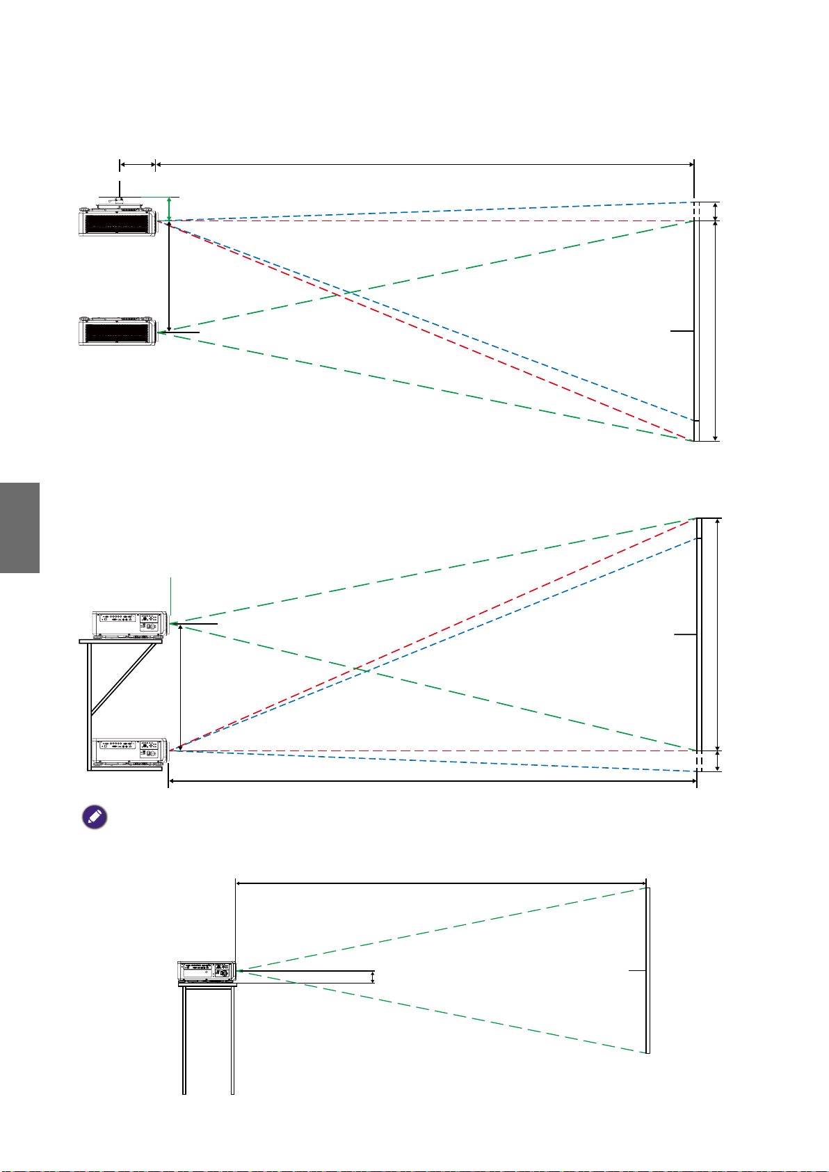
Posizione di installazione
CX
0.1H
0.1H
C
Installazione a soffitto
Range
spostamento
Parte superiore dello schermo
Italiano
Installazione su scrivania
Range spostamento
Centro dello schermo
Centro dello schermo
H
H
C
Nota:
• la funzione di spostamento dell'obiettivo è disponibile su LS1ST3 (obiettivo fisso). Questo obiettivo deve essere
usato per le applicazioni a "zero gradi"/"nessun offset". Vedere di seguito:
117.4
SOLO PER L'USO CON LS1ST3 (OBIETTIVO FISSO)
60
Centro dello schermo

Dimensioni
152.5
Dimensioni scocca
AIR IN
RELEASE BUTTON
95
220
28
ADJ. FOOT
AC IN
R SIDE COVER
ADJ. FOOT
300
150
152.50
100
300
REAR COVER
FRONT RING
FRONT COVER
AIR IN
BASE COVER
582.80
216
547.26
L SIDE COVER
AIR IN
Italiano
AIR OUT
500
TOP COVER
REAR IR WINDOW
MODEL LOGO
NAME PLATE
FRONT IR
LED STATUS
Dimensioni foro di montaggio a soffitto
6-CEILING MOUNT HOLE
M4*0.7 SCREW L=16 mm (MAX.)
150
150
100
300
Unit: mm
61
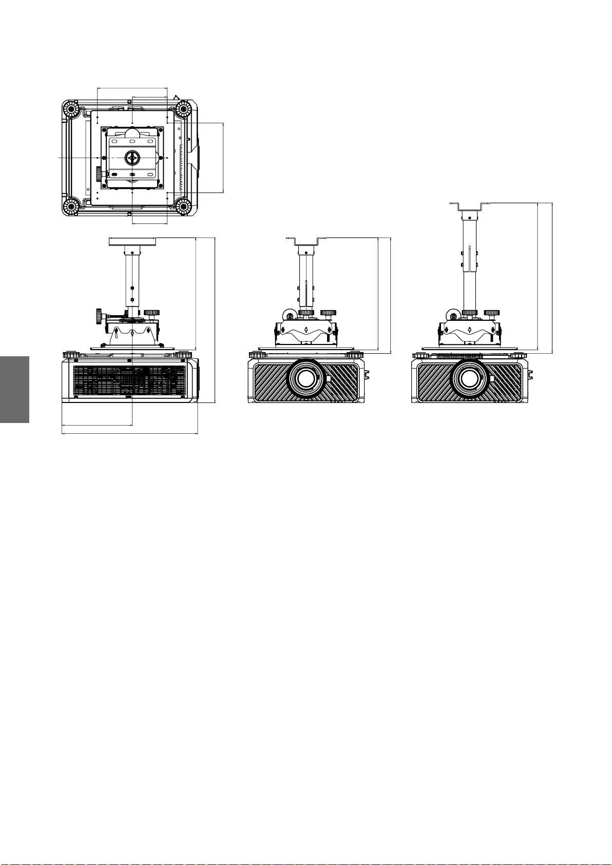
Italiano
302.5
582.8
633.50
648.50
150
150
300
300
483.60
710.70
483.60
498.60
Dimensioni montaggio a soffitto (CMG6)
62
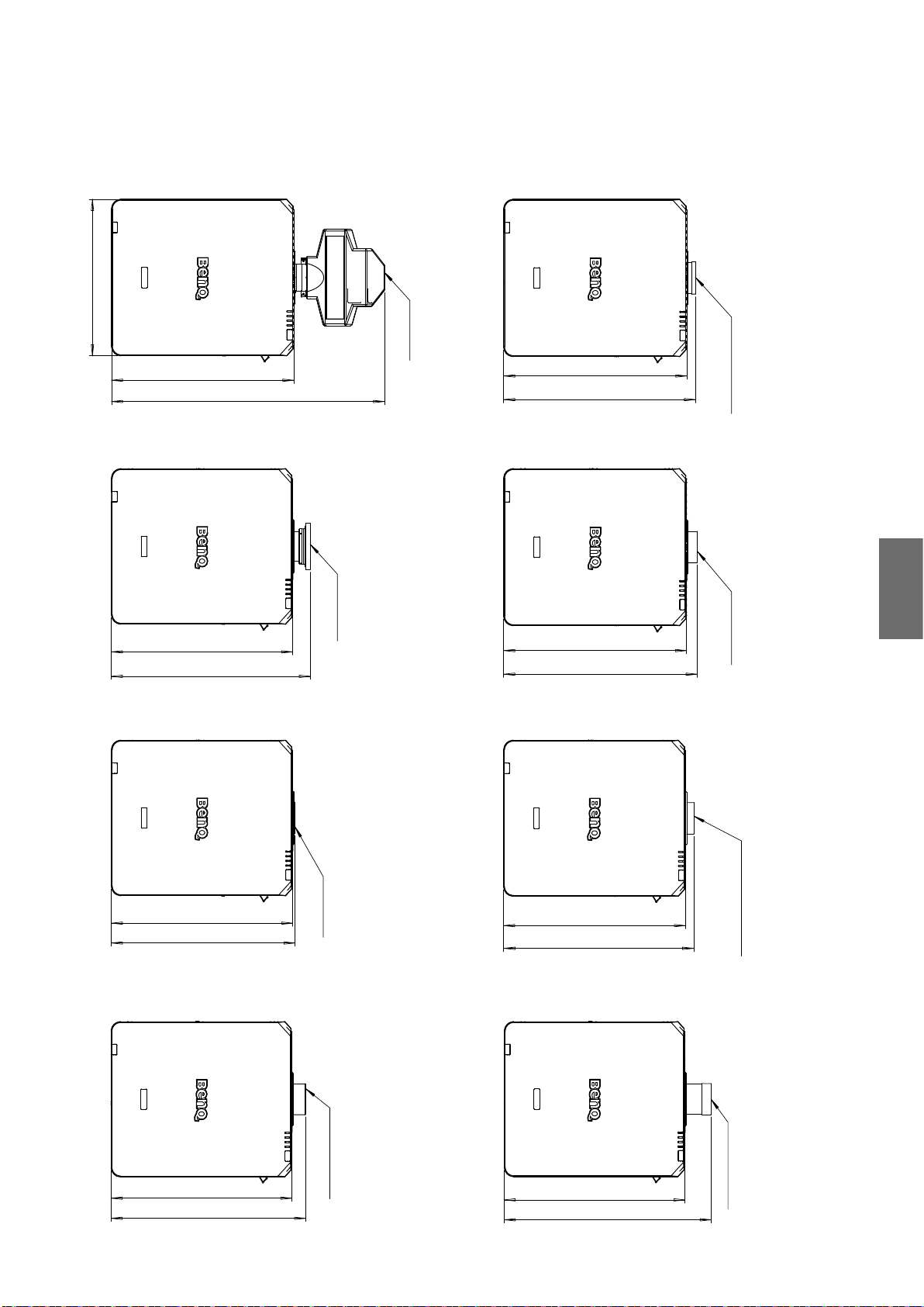
Dimensioni obiettivo ottico
Obiettivo opzionale (UST: LSIST4)
500
UST LENS
Obiettivo opzionale
(AMPIEZZA FISSA: LSIST3)
WIDE FIX LENS
582.80
872.5
Obiettivo opzionale (UWZ: LSIST2)
UWZ LENS
582.80
639.4
Obiettivo opzionale (STD: LSISD)
582.80
610.16
Obiettivo opzionale (AMPIO: LSIST1)
Italiano
WIDE LENS
582.8
616.5
Obiettivo opzionale (SEMI: LSILT1)
STD LENS
582.80
590.7
Obiettivo opzionale (LUNGO1: LSILT2)
LONG 1 LENS
582.80
626.7
SEMI LONG LENS
582.80
609.90
Obiettivo opzionale (LUNGO2: LSILT3)
LONG2 LENS
582.80
667.3
63

Italiano
Indicatore LED
Messaggi indicatore
Diversi messaggi indicatore sono utilizzati dal proiettore per avvisare gli utenti dei problemi
relativi all'impostazione o per errori di sistema. I LED sul coperchio superiore del proiettore sono
illustrati di seguito.
LED TEMP (TEMPERATURA)
Visualizzazione LED Stato del proiettore Operazioni suggerite
Spento Stato normale
Lampeggiante Rosso
Errore temperatura
eccessiva
Contattare il rivenditore autorizzato più vicino o il
centro assistenza.
LED LIGHT SOURCE (SORGENTE DI ILLUMINAZIONE)
Visualizzazione LED Stato del proiettore Operazioni suggerite
Spento
Lampeggiante
Acceso
Verde Proiettore acceso
Rosso (6 cicli)
Rosso
Verde
Sorgente di illuminazione
spenta
Sorgente di illuminazione
quasi esaurita
Problema con la sorgente
di illuminazione
Sorgente di illuminazione
accesa
Contattare il centro assistenza locale.
Contattare il centro assistenza locale.
Indicatore LED STATUS (STATO)
Visualizzazione LED Stato del proiettore Operazioni suggerite
Spento Normale
Rosso (una
Lampeggiante
Illuminato Rosso Errore di sistema Contattare il centro assistenza locale.
volta)
Rosso
(quattro volte)
Errore interruttore
sicurezza
Errore ventola Contattare il centro assistenza locale.
Verificare che il coperchio superiore sia montato
correttamente o se è installato o meno l'obiettivo. Se il
problema persiste, contattare il centro assistenza locale.
64

Indicatore LED POWER (ACCENSIONE)
Visualizzazione LED Stato del proiettore Operazioni suggerite
Spento
Lampeggiante
Illuminato
Alimentazione CA
disattiva
Verde Il proiettore è alimentato Attendere che il proiettore inizia a proiettare.
Arancione
Rosso Modalità standby
Verde Proiettore acceso
Raffreddamento del
proiettore in corso
Verificare la sorgente di alimentazione CA e accendere
il proiettore.
Per accendere il proiettore, premere il tasto ON sul
telecomando o il tasto Accensione sul pannello di
controllo.
Italiano
65

Índice
Aviso ......................................................................................................67
Ilustración de ventilación .............................................................................................67
Requisitos de la rejilla de ventilación ..........................................................................67
Interruptor de tensión ..................................................................................................68
Precaución durante la instalación ...............................................................................68
Información del producto ...................................................................69
Contenido de la caja .....................................................................................................69
Especificaciones del proyector ....................................................................................69
Terminales .....................................................................................................................70
Mando a distancia .........................................................................................................71
Configuración de ID del mando a distancia ...............................................................71
Instalación .............................................................................................72
Especificaciones de la lente ..........................................................................................72
Mesa de proyección ......................................................................................................73
Desplazamiento de la lente .........................................................................................75
Español
Colocación de la instalación.........................................................................................76
Dimensiones .........................................................................................77
Dimensiones del armario .............................................................................................77
Dimensiones de los orificios de montaje en el techo ................................................77
Dimensiones de montaje en el techo (CMG6) ..........................................................78
Dimensiones de la lente opcional ................................................................................79
Indicación LED .....................................................................................80
Visite el siguiente sitio web para ver la última versión del Manual de usuario / Guía de
instalación.
http://business-display.benq.com/
10/12/18
66

Aviso
Ilustración de ventilación
Entrada de aire
Entrada de aire
Salida de aire
Requisitos de la rejilla de ventilación
Para que la ventilación del proyector sea adecuada, asegúrese de dejar un espacio libre alrededor
del proyector como se indica a continuación:
11,8 pulgada /
30 cm
o superior
19,7 pulgada / 50 cm
o superior
HDBaseT / LAN
3D Sync Out
RGB IN
RS-232 USBTRIGGER
CENTER
AUTO
POWER
SHUTTER
LENS
INPUT
DVI-D
Display Port
HDMI
R/Pr G/Y B/Pb
HV
RGB OUT
WIRE
MENU EXIT
SYNC ASPECT
FOCUS
LENS
SHIFT
ZOOM
11,8 pulgada /
30 cm
o superior
19,7 pulgada / 50 cm
o superior
Español
67

Mínimo
11,8 pulgada / 30 cm
Mínimo
19,7 pulgada /
50 cm
RS-232 USBTRIGGER
Display PortDVI-D
WIRE
R/Pr G/YB/Pb
RGB IN
HV
RGB OUT
HDMI
HDBaseT / LAN
3D Sync Out
MENU EXIT
SHIFT
LENS
FOCUS
ZOOM
INPUT
SYNC ASPECT
LENS
SHUTTER
POWER
AUTO
CENTER
Mínimo
39,3 pulgada /
100 cm
Interruptor de tensión
Asegúrese de que el interruptor de tensión tiene la tensión adecuada según la región en la que se
vaya a utilizar el proyector.
Nota:
El ajuste predeterminado es 230 V.
Español
Precaución durante la instalación
• Apague el proyector cuando cambie o extraiga la lente. Si no, el proyector se apagará
inmediatamente sin el procedimiento normal.
• Para evitar daños en los chips DLP, no apunte nunca con un rayo láser de alta potencia a la
lente de proyección.
68

Información del producto
MENU
EXIT
ENTER
1
4
7089
635
2
Contenido de la caja
Saque con cuidado el contenido y compruebe que tiene todos los artículos indicados a
continuación. Dependiendo del lugar donde lo haya adquirido, puede que algunos de los elementos
no estén disponibles. Por favor, compruébelo según el lugar donde lo adquirió.
Proyector
sin lente
Cable VGA
Mando a distancia
sin pilas AA
Cable para conexión
remota
Guía de instalación
Tornillo antirrobo
Especificaciones del proyector
Especificaciones LU9915
Sistema de proyección Chip DLP Single 0,67" WUXGA DMD
Resolución nativa WUXGA (1920 x 1200)
Brillo 10.000 Lúmenes
Cable de
alimentación
Tapa de habitáculo
de la lente
Español
Relación de aspecto 16:10
Fuente de luz Fuente de luz láser
Consumo de energía 1290 W a 100 V, 1215 W a 240 V
Dimensiones 583 mm (L) x 500 mm (An) x 211 mm (Al)
Peso 28 kg / 61,7 libras (sin incluir la lente)
Temperatura de
De 0ºC a 40ºC (de 32ºF a 104ºF)
funcionamiento
Nota:
• El brillo se suministra mediante una lente estándar. El valor variará dependiendo de las lentes instaladas.
• La salida de brillo variará dependiendo de cada unidad y del uso real.
• Visite el sitio web local de http://www.benq.com para ver el manual de usuario más reciente.
69

Terminales
Español
TRIGGER
WIRED
REMOTE HDBaseT/LANDVI-D DISPLAYPORT
RS-232TRIGGER
COMPUTER 2
MONITOR OUTCOMPUTER 1
R/PrG/YB/PbHV
3G-SDI
IN
OUT HDMI
3D SYNC OUT
3D SYNC IN
• HDBaseT/LAN
Permite la conexión de un cable Ethernet RJ45 Cat5/Cat6 para la entrada no comprimida de
vídeo de alta definición (HD) y señales de control.
• 3D Sync Out
Permite la conexión a un transmisor de señal de sincr. 3D por infrarrojos.
• 3D Sync In
Permite la conexión a la entrada de señal de sincronización 3D.
• DVI-D
Conexión a fuente DVI-D.
• HDMI
Permite la conexión a una fuente HDMI.
• DisplayPort
Permite la conexión a un dispositivo o PC con DisplayPort.
• 3G-SDI
Conexión a fuente 3G-SDI.
• Computer 1
Puerto VGA de 15 patillas para la conexión a RGB, fuente HD o PC.
• Computer 2 (V, H, B/Pb, G/Y, R/Pr)
Conexión a una señal de salida RGB o YPbPr/YCbCr con un terminal de entrada de tipo BNC.
• Monitor Out
Conexión a otro equipo de visualización para una reproducción simultánea.
• RS-232
Interfaz D-sub de 9 patillas estándar para la conexión a un sistema de control de PC y para el
mantenimiento del proyector.
• TRIGGER
Mini-clavija de auricular de 3,5 mm, con relé de visualización de 350 mA para proporcionar una
salida de 12 (+/-1,5) V y protección contra cortocircuito.
• Wired Remote
Conexión a un sistema repetidor por infrarrojos compatible con las entradas Niles o Xantech.
Nota:
Asegúrese de que el puerto es válido antes de insertar un mando a distancia por cable. El mando a distancia se puede
dañar si el puerto no es válido, p. ej.: si hay un mando a distancia por cable conectado a una salida del disparador.
70

Mando a distancia
89
ON OFF
ZOOM +/-
FOCUS +/-
Arriba
Izquierda
MENU
AUTO PC
COMPUTER 1
COMPUTER 2
HDMI 1
3G-SDI
DisplayPort
CLEAR
Botones numéricos
MENU
TEST PATTERN
LENS-SHIFT
ENTER
ENTER
EXIT
1
4
7
3
2
6
5
0
Derecha
Abajo
EXIT
BLANK
STATUS
ASPECT
DVI
HDMI 2
HDBaseT
ID SET
FREEZE
Configuración de ID del mando a distancia
Puede ajustar el ID del mando a distancia para que controle un proyector concreto.
Ajuste el ID del proyector (de 01 a 99) utilizando los menús OSD. Tras configurar un ID diferente,
el mando a distancia solo controlará el proyector correspondiente.
Pulse las teclas ID SET + MENU al mismo tiempo durante 5 segundos y la retroiluminación del
mando a distancia parpadeará una vez para luego acceder al modo Configuración de ID.
Vuelva a hacer clic en las teclas ID SET + MENU durante 5 segundos (la retroiluminación
parpadeará 1 vez) para salir del modo Configuración de ID.
Tras acceder al modo Configuración de ID, mantenga pulsada la tecla ID SET durante 3 segundos.
La luz LED del mando a distancia parpadeará y se encenderá la retroiluminación. Entretanto, pulse
el número para configurar el ID del mando a distancia.
Por ejemplo, para ajustar el ID del mando a distancia "01", pulse la tecla 0 durante 1 segundo (la
luz LED parpadeará 3 veces y luego se apagará la retroiluminación). Luego pulse 1 tecla durante 1
segundo (la luz LED parpadea 3 veces y luego se apagará la retroiluminación).
Para ajustar el ID del mando a distancia en "19", pulse 1 tecla durante 1 segundo y luego pulse la
tecla 9 durante 1 segundo.
Español
71

Instalación
Especificaciones de la lente
Nombre del
modelo
LS1ST4
LS1ST3 Ancha fija 5J.JAM37.011 F=1,85, f=11,6 mm 0,76:1 Fija 910 g
LS1ST2 Ultra-ancha 5J.JAM37.061
LS1ST1
LS1SD Estándar 5J.JAM37.001
LS1LT1 Semi-larga 5J.JAM37.051
LS1LT2 Zoom largo 1 5J.JAM37.031
LS1LT3 Zoom largo 2 5J.JAM37.041
Tipo de lente
Distancia
ultracorta
Zoom de gran
angular
Núm. de pieza
BenQ
5J.JCY37.002 F=2,0, f=5,64 mm 0,38:1 Fija 2.710 g
5J.JAM37.021
Espec. óptica
F=1,96~2,3,
f=11,3~14,1 mm
F=1,85~2,5,
f=18,7~26,5 mm
F=1,7~1,9,
f=26~34 mm
F=1,86~2,48,
f=32,9~54,2 mm
F=1,85~2,41,
f=52,8~79,1 mm
F=1,85~2,48,
f=78,5~121,9 mm
Factor de
proyección
0,75~0,93:1 1,25:1 1.280 g
1,25~1,79:1 1,41:1 1.090g
1,73~2,27:1 1,3:1 820g
2,22~3,67:1 1,65:1 950g
3,58~5,38:1 1,5:1 1.020 g
5,31~8,26:1 1,55:1 1.350 g
Relación de
zoom
Peso*
Español
Nota:
Los valores enumerados en la tabla anterior son la media y pueden variar según el modelo.
72

Mesa de proyección
Lente ancha fija, Lente con zoom de gran angular, Lente STD,
Lente de zoom 1 semi larga, Lente zoom largo 1, Lente zoom
largo 2, Lente de zoom ultra ancha
Centrar
lente
Altura (B)
PANTALLA
Distancia (A)
LU9915
Tamaño de pantalla 5J.JAM37.011 5J.JAM37.021 5J.JAM37.001 5J.JAM37.051
Lente fija ancha Lente con zoom de gran angular Lente STD Lente de zoom 1 semi larga
Diagonal Ancho Altura (B) Distancia (A)
Fija Gran angular Tele Gran angular Tele Gran angular Tele
(pulgada) (m) (pulgada) (m) (pulgada) (m) (pulgada) (m) (pulgada) (m) (pulgada) (m) (pulgada) (m) (pulgada) (m) (pulgada) (m) (pulgada) (m)
40 1,02 34 0,86 21 0,54 25,1 0,64 41,4 1,05 59,9 1,52 57,2 1,45 75,8 1,93 73,6 1,87 124,1 3,15
50 1,27 42 1,08 26 0,67 31,8 0,81 52,3 1,33 75,4 1,92 72,1 1,83 95,5 2,42 92,9 2,36 155,9 3,96
60 1,52 51 1,29 32 0,81 38,5 0,98 63,1 1,60 90,9 2,31 87,1 2,21 115,1 2,92 112,1 2,85 187,8 4,77
80 2,03 68 1,72 42 1,08 52,0 1,32 84,9 2,16 121,8 3,09 117,0 2,97 154,3 3,92 150,5 3,82 251,4 6,39
100 2,54 85 2,15 53 1,35 65,5 1,66 106,6 2,71 152,7 3,88 147,0 3,73 193,5 4,92 188,9 4,80 315,0 8,00
120 3,05 102 2,58 64 1,62 78,9 2,01 128,4 3,26 183,6 4,66 176,9 4,49 232,8 5,91 227,6 5,78 378,6 9,62
150 3,81 127 3,23 79 2,02 99,1 2,52 161,0 4,09 230,0 5,84 221,8 5,63 291,6 7,41 285,0 7,24 474,1 12,04
180 4,57 153 3,88 95 2,42 119,3 3,03 193,6 4,92 276,4 7,02 266,7 6,77 350,5 8,90 342,6 8,70 569,5 14,47
200 5,08 170 4,31 106 2,69 132,8 3,37 215,3 5,47 307,3 7,81 296,6 7,53 389,7 9,90 381,0 9,68 633,1 16,08
300 7,62 254 6,46 159 4,04 200,1 5,08 324,0 8,23 461,9 11,73 446,3 11,34 585,9 14,9 573,2 14,56 951,2 24,16
400 10,16 339 8,62 212 5,38 267,4 6,79 432,7 10,99 616,6 15,66 595,9 15,14 782,3 19,87 765,3 19,44 1269,7 32,25
500 12,70 424 10,77 265 6,73 334,8 8,50 541,5 13,75 771,2 19,59 745,6 18,94 978,3 24,85 957,4 24,32 1587,8 40,33
Tamaño de pantalla 5J.JAM37.031 5J.JAM37.041 5J.JAM37.061
Lente de zoom 1 larga Lente de zoom 2 larga Lente de zoom ultra ancha
Diagonal Ancho Altura (B) Distancia (A)
Gran angular Tele Gran angular Tele Gran angular Tele
(pulgada) (m) (pulgada) (m) (pulgada) (m) (pulgada) (m) (pulgada) (m) (pulgada) (m) (pulgada) (m) (pulgada) (m) (pulgada) (m)
40 1,02 34 0,86 21 0,54 118,7 3,01 181,0 4,60 173,9 4,42 277,7 7,05 24,5 0,62 31,1 0,79
50 1,27 42 1,08 26 0,67 149,7 3,80 227,6 5,78 220,2 5,59 350,0 8,89 31,1 0,79 39,2 1,00
60 1,52 51 1,29 32 0,81 180,7 4,59 274,1 6,96 266,6 6,77 422,3 10,73 37,6 0,96 47,4 1,20
80 2,03 68 1,72 42 1,08 242,7 6,16 367,3 9,33 359,4 9,13 567,0 14,40 50,8 1,29 63,8 1,62
100 2,54 85 2,15 53 1,35 304,3 7,73 460,4 11,70 452,1 11,48 711,6 18,07 63,9 1,62 80,2 2,04
120 3,05 102 2,58 64 1,62 366,7 9,31 553,6 14,06 544,9 13,84 856,2 21,75 77,1 1,96 96,6 2,45
150 3,81 127 3,23 79 2,02 459,4 11,67 693,3 17,61 684,0 17,37 1073,1 27,26 96,8 2,46 121,1 3,08
180 4,57 153 3,88 95 2,42 552,4 14,03 833,0 21,16 823,1 20,91 1290,1 32,77 116,5 2,96 145,7 3,70
200 5,08 170 4,31 106 2,69 614,7 15,6 926,4 23,53 915,9 23,26 1434,7 36,44 129,7 3,29 162,1 4,12
300 7,62 254 6,46 159 4,04 924,0 23,47 1392,1 35,36 1379,6 35,04 2157,8 54,81 195,4 4,96 244,0 6,20
400 10,16 339 8,62 212 5,38 1233,9 31,34 1857,9 47,19 1843,3 46,82 2880,9 73,18 261,2 6,63 325,9 8,28
500 12,70 424 10,77 265 6,73 1543,7 39,21 2323,6 59,02 2307,1 58,60 3604,0 91,54 326,9 8,30 407,7 10,36
Español
73

Reflejo ultracorto
Pantalla
L1
H1
216
120
285
873
L2
Español
H2
㻸㻟
L1: Desde la pantalla al punto del espejo
L2: Desde la pantalla a la parte delantera del proyector
L3: Desde la pantalla a la parte posterior del proyector
H1: Desde la parte inferior de la pantalla a la parte superior del proyector
H2: Desde la parte inferior de la pantalla a la parte inferior del proyector
Tamaño de pantalla 5J.JCY37.001
Reflejo ultracorto
Diagonal Ancho Altura H1 H2 L1 L2 L3
pulgada mm pulgada mm pulgada mm pulgada mm pulgada mm pulgada mm pulgada mm pulgada mm
100 2540 85 2166 53 1355 19 485 28 701 33 849 22 564 -1 -24
120 3048 102 2599 64 1627 23 596 32 812 39 1000 28 715 5 127
150 3810 128 3247 80 2032 30 763 39 979 48 1227 37 942 14 354
200 5080 170 4330 107 2711 41 1041 49 1257 63 1606 52 1321 29 733
250 6350 213 5415 133 3391 52 1320 60 1536 78 1984 67 1699 44 1111
300 7620 256 6500 160 4071 63 1598 71 1814 93 2362 82 2077 59 1489
350 8890 299 7585 187 4752 74 1877 82 2093 108 2741 97 2456 74 1868
Nota:
• Para obtener unas instrucciones más visuales, vaya al sitio web de la calculadora de BenQ:
http://projectorcalculator.benq.com/.
• Es preferible que sean profesionales los que lleven a cabo una instalación precisa. Para más información, póngase en
contacto con su distribuidor.
• Al instalar la lente UST en el proyector, se recomienda aflojar el tornillo del kit de soporte y hacer que el brazo
sea móvil antes de realizar el ajuste.
• En el sitio web local de BenQ, encontrará el Manual de usuario para la instalación de la Lente UST.
74
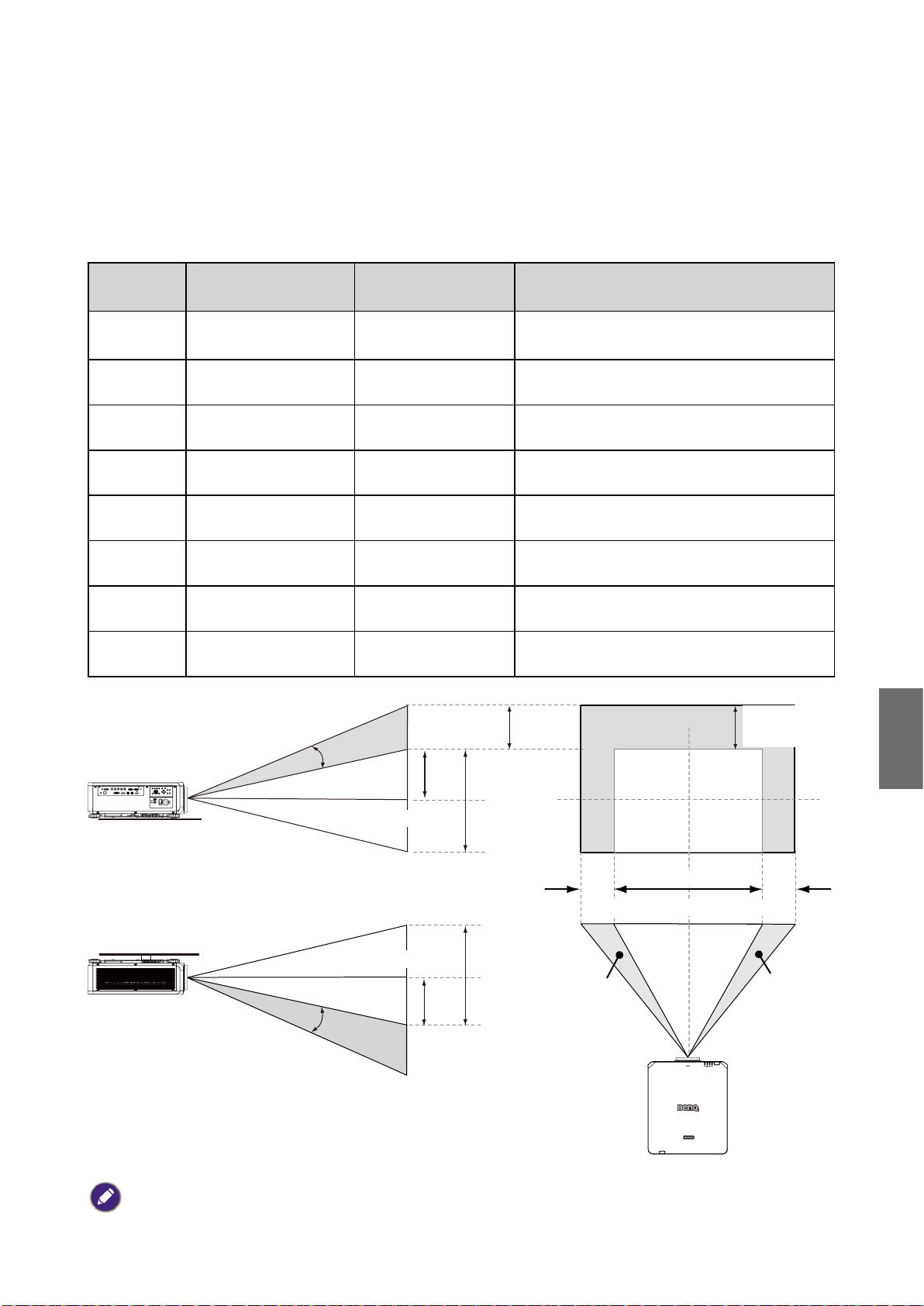
Desplazamiento de la lente
Intervalo de ajuste del desplazamiento de la lente
A continuación se explica el intervalo de ajuste del desplazamiento de la lente, sujeto a las
condiciones enumeradas.
Nombre del
modelo
LS1ST4 Distancia ultracorta 5J.JCY37.001
Tipo de lente Núm. de pieza BenQ Intervalo de desplazamiento de la lente
-3% ~ +7% Vertical; -5% ~ +5% Horizontal
(Posición central en 56,5%)
LS1ST3 Ancha fija 5J.JAM37.011 ND
LS1ST2 Ultra-ancha 5J.JAM37.061 0 ~ +50% Vertical; -6,7% ~ +6,7% Horizontal
LS1ST1 Zoom de gran angular 5J.JAM37.021 0 ~ +50% Vertical; -10% ~ +10% Horizontal
LS1SD Estándar 5J.JAM37.001 0 ~ +50% Vertical; -10% ~ +10% Horizontal
LS1LT1 Semi-larga 5J.JAM37.051 0 ~ +50% Vertical; -10% ~ +10% Horizontal
LS1LT2 Zoom largo 1 5J.JAM37.031 0 ~ +50% Vertical; -10% ~ +10% Horizontal
LS1LT3 Zoom largo 2 5J.JAM37.041 0 ~ +50% Vertical; -10% ~ +10% Horizontal
Proyección frontal-escritorio
Desplazamiento vertical
Área de
desplazamiento
vertical
Español
Altura de la imagen proyectada
Proyección frontal-Montaje en techo
Altura de la imagen proyectada
Desplazamiento vertical
Nota:
Máx.
0,5 V
Máx.
0,5 V
1 V
1 V
0,1 Alt.
Desplazamiento
horizontal a
izquierda
1 Alt.
Ancho de la imagen proyectada
Desplazamiento
horizontal a
derecha
0,1 Alt.
Los dibujos anteriores se aplican únicamente a la lente estándar.
75
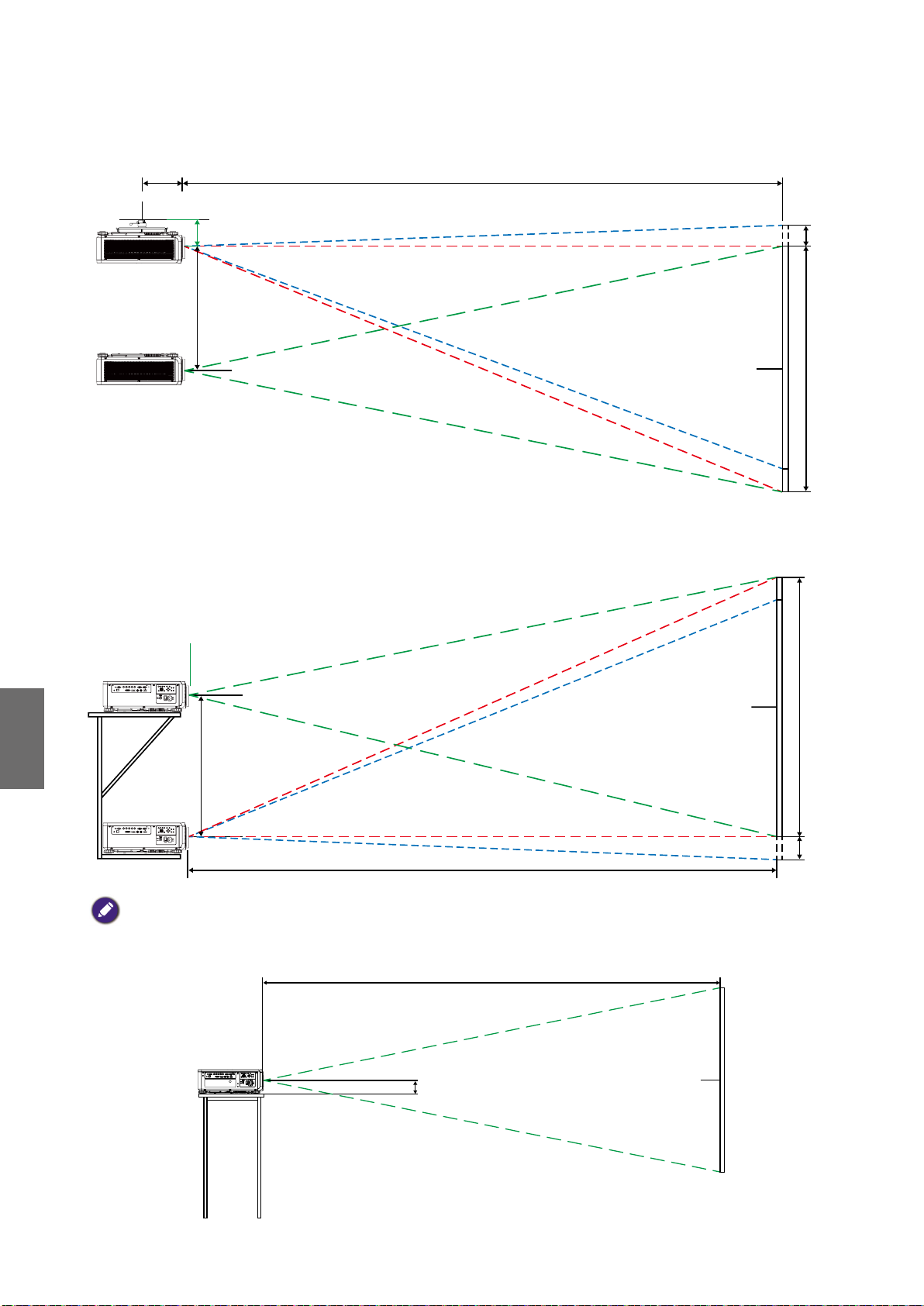
Colocación de la instalación
CX
0.1H
0.1H
C
Instalación para montaje en el techo
Intervalo de
desplazamiento
Parte superior de pantalla
Español
Instalación sobre una mesa
Intervalo de
desplazamiento
Centro de pantalla
Centro de pantalla
H
H
C
Nota:
• La función Desplazamiento de lente no está disponible en el modelo LS1ST3 (lente fija). Esta lente se debería
utilizar en las aplicaciones de "grado cero"/"sin desplazamiento". Ver a continuación:
117.4
PARA UTILIZAR SÓLO CON LS1ST3 (LENTE FIJA)
76
Centro de pantalla
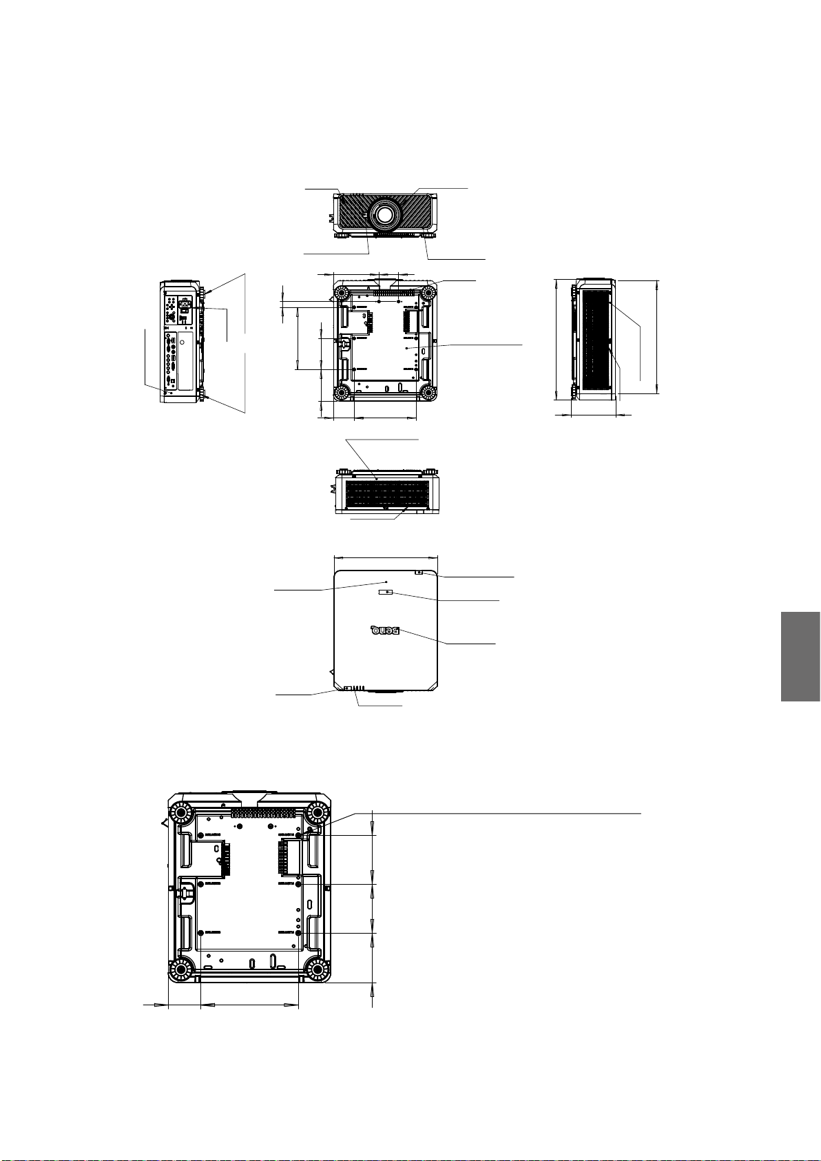
Dimensiones
152.5
Dimensiones del armario
AIR IN
RELEASE BUTTON
95
220
28
ADJ. FOOT
AC IN
R SIDE COVER
ADJ. FOOT
300
TOP COVER
150
152.50
100
300
REAR COVER
AIR OUT
500
FRONT RING
FRONT COVER
AIR IN
BASE COVER
REAR IR WINDOW
MODEL LOGO
582.80
216
547.26
L SIDE COVER
AIR IN
NAME PLATE
FRONT IR
LED STATUS
Unit: mm
Dimensiones de los orificios de montaje en el techo
6-CEILING MOUNT HOLE
M4*0.7 SCREW L=16 mm (MAX.)
150
150
100
300
Español
77

Dimensiones de montaje en el techo (CMG6)
302.5
582.8
633.50
648.50
150
150
300
300
483.60
710.70
483.60
498.60
Español
78

Dimensiones de la lente opcional
Lente opcional (UST: LSIST4) Lente opcional (FIJA ANCHA: LSIST3)
500
UST LENS
WIDE FIX LENS
582.80
872.5
Lente opcional (UWZ: LSIST2)
UWZ LENS
582.80
639.4
Lente opcional (STD: LSISD)
582.80
610.16
Lente opcional (GRAN
ANGULAR: LSIST1)
WIDE LENS
582.8
616.5
Lente opcional (SEMI: LSILT1)
Español
STD LENS
582.80
590.7
Lente opcional (LARGO1: LSILT2)
LONG 1 LENS
582.80
626.7
SEMI LONG LENS
582.80
609.90
Lente opcional (LARGO2: LSIST3)
LONG2 LENS
582.80
667.3
79

Indicación LED
Mensajes indicadores
El proyector usa varios mensajes indicadores para alertar a los usuarios de problemas con la
configuración o errores del sistema. Los LED de la tapa superior del proyector que se indican a
continuación.
LED TEMP
Visualización LED Estado del proyector Consejos de funcionamiento
Apagado Estado normal
Parpadeante Rojo
Error de exceso de
temperatura
Póngase en contacto con su distribuidor autorizado
o con su centro de asistencia técnica más cercano.
Español
LED DE LIGHT SOURCE (FUENTE DE LUZ)
Visualización LED Estado del proyector Consejos de funcionamiento
Apagado
Verde
Parpadeante
Rojo (Ciclos de 6)
Rojo
Encendido
Verde
La fuente de luz está
apagada
El proyector se está
encendiendo
Se ha agotado la fuente
de luz
Problema con la fuente
de luz
La fuente de luz está
encendida
Llame al centro de servicio local.
Llame al centro de servicio local.
Indicador LED STATUS
Visualización LED Estado del proyector Consejos de funcionamiento
Apagado Normal
Parpadeante
Iluminado Rojo Error en el sistema Llame al centro de servicio local.
Rojo (una vez)
Rojo (cuádruple) Error en ventilador Llame al centro de servicio local.
Error del interruptor de
seguridad
Compruebe si la tapa superior está bien montada o
la lente está bien instalada. Si el problema persiste,
llame al centro de servicio local.
80

Indicador LED POWER (ALIMENTACIÓN)
Visualización LED Estado del proyector Consejos de funcionamiento
Apagado Sin corriente alterna
Verde
Parpadeante
Naranja
Rojo Modo de espera
Iluminado
Verde
Preparado para encender
el proyector
El proyector se está
refrigerando
El proyector está
encendido
Compruebe la fuente de alimentación de CA y
encienda el proyector.
Espere hasta que el proyector inicie la proyección.
Para encender el proyector, pulse la tecla ON en el
mando a distancia o la tecla de encendido en el panel
de control.
Español
81

목차
알림 ........................................................................................................83
통풍 그림
배기구 요구 사항
전압 스위치
설치 시 주의 사항
.........................................................................................................................
............................................................................................................
.....................................................................................................................
...........................................................................................................
83
83
84
84
제품 정보 ................................................................................................ 85
포장 내용물
프로젝터 사양
단자 .................................................................................................................................86
리모컨 .............................................................................................................................87
리모컨 ID 설정
.....................................................................................................................
.................................................................................................................
................................................................................................................
85
85
87
설치 ........................................................................................................88
렌즈 사양
영사 표 ............................................................................................................................89
렌즈 이동.........................................................................................................................91
설치 위치.........................................................................................................................92
.........................................................................................................................
88
크기 ........................................................................................................93
캐비넷 크기
천장 장착 구멍 크기
천장 장착 크기 (CMG6) .................................................................................................94
옵션 렌즈 크기 ................................................................................................................95
.....................................................................................................................
........................................................................................................
93
93
LED 표시등 ............................................................................................ 96
한국어
최신 버전의 사용 설명서 / 설치 안내서를 보려면 아래 웹사이트를 방문하십시오 .
http://business-display.benq.com/
10/12/18
82

알림
통풍 그림
공기 흡입구
공기 흡입구
공기 배기구
배기구 요구 사항
프로젝터의 적절한 통풍을 위해 , 아래 그림에 나온 것처럼 프로젝터 주위에 약간의 공간을
두어야 합니다 .
11.8 인치 /
30 cm
이상
19.7 인치 / 50 cm
이상
HDBaseT / LAN
3D Sync Out
RGB IN
RS-232 USBTRIGGER
CENTER
AUTO
POWER
SHUTTER
LENS
INPUT
DVI-D
Display Port
HDMI
R/Pr G/Y B/Pb
HV
RGB OUT
WIRE
MENU EXIT
SYNC ASPECT
FOCUS
ZOOM
LENS
SHIFT
11.8 인치 /
30 cm
이상
19.7 인치 / 50 cm
이상
한국어
83

최소
11.8 인치 / 30 cm
최소
19.7 인치 / 50 cm
RS-232 USBTRIGGER
Display PortDVI-D
WIRE
R/Pr G/YB/Pb
RGB IN
HV
RGB OUT
HDMI
HDBaseT / LAN
3D Sync Out
MENU EXIT
SHIFT
LENS
FOCUS
ZOOM
INPUT
SYNC ASPECT
LENS
SHUTTER
POWER
AUTO
CENTER
39.3 인치 / 100 cm
전압 스위치
전압 스위치가 프로젝터를 사용 중인 지역에 맞는 올바른 전압에 선택되어 있는지
확인하십시오 .
참고 :
기본 설정은 230 V 입니다 .
최소
한국어
설치 시 주의 사항
• 렌즈를 바꾸거나 제거할 때는 프로젝터를 끄십시오 . 그렇지 않을 경우 프로젝터는
정상적인 절차 없이 즉시종료됩니다 .
• DLP 칩 손상을 방지하려면 고전원 레이저 빔을 영사 렌즈에 맞추지 마십시오 .
84

제품 정보
MENU
EXIT
ENTER
1
4
7089
635
2
포장 내용물
조심해서 포장을 뜯고 다음 항목이 있는지 확인하십시오 . 구입 지역에 따라 일부 품목이
제공되지 않을 수 있습니다 . 구입처에 확인하십시오 .
프로젝터
렌즈 불포함
리모컨
AA 배터리 불포함
VGA 케이블 유선 리모컨 케이블
프로젝터 사양
사양 LU9915
영사 시스템 DLP 단일 0.67" WUXGA DMD 칩
원시 해상도 WUXGA (1920 x 1200)
밝기 10,000 루멘
화면비 16:10
설치 안내서
전원 케이블
도난 방지 나사 렌즈 뚜껑
한국어
광원 레이저 광원
소비 전력 1290W@100V, 1215W@240V
크기 583 mm (L) x 500 mm (W) x 211 mm (H)
무게 28 kg / 61.7 lbs( 렌즈 제외 )
작동 온도 32ºF ~ 104ºF (0ºC ~ 40ºC )
참고 :
• 밝기는 표준 렌즈를 통해 제공됩니다 . 값은 설치된 렌즈에 따라 다릅니다 .
• 밝기 출력은 각 유닛과 실제 사용에 따라 다릅니다 .
• 최신 사용 설명서를 보려면 http://www.benq.com 에서 현지 웹사이트를 방문하십시오 .
85

단자
TRIGGER
WIRED
REMOTE HDBaseT/LANDVI-D DISPLAYPORT
RS-232TRIGGER
COMPUTER 2
MONITOR OUTCOMPUTER 1
R/PrG/YB/PbHV
3G-SDI
IN
OUT HDMI
3D SYNC OUT
3D SYNC IN
• HDBaseT/LAN
RJ45 Cat5/Cat6 이더넷 케이블을 비압축 입력 고선명 비디오 (HD) 제어 신호에 연결하는
데 사용됩니다 .
• 3D Sync Out
3D IR 동기화 신호 송신기에 연결됩니다 .
• 3D Sync In
3D 동기화 신호 입력에 연결됩니다 .
• DVI-D
DVI-D 소스에 연결됩니다 .
• HDMI
HDMI 소스에 연결됩니다 .
• DisplayPort
DisplayPort 가 장착된 장치 또는 PC 에 연결됩니다 .
• 3G-SDI
3G-SDI 소스에 연결됩니다 .
• Computer 1
RGB, 컴포넌트 HD 소스 또는 PC 에 연결할 수 있는 15 핀 VGA 포트입니다 .
• Computer 2 (V, H, B/Pb, G/Y, R/Pr)
BNC 유형 입력 단자를 사용하여 RGB 또는 YPbPr/YCbCr 출력 신호에 연결됩니다 .
• Monitor Out
동시 재생을 표시할 수 있도록 다른 디스플레이 장비에 연결됩니다 .
• RS-232
PC 제어 시스템에 연결하고 프로젝터 유지 보수를 수행할 수 있는 표준 9 핀 D-sub
인터페이스입니다 .
한국어
• TRIGGER
3.5 mm 미니 이어폰 잭으로 , 350 mA 디스플레이 계전기를 사용하여 12 (+/-1.5) V 출력 및
단락 보호를 제공합니다 .
• Wired Remote
입력 Niles 또는 Xantech 호환 IR 리피터 시스템에 연결됩니다 .
참고 :
유선 리모컨을 삽입하기 전에 포트가 유효한지 확인하십시오 . 잘못된 포트를 사용하면 리모컨이 손상될 수
있습니다 ( 예 : 유선 리모컨이 트리거 출력에 연결됨 ).
86

리모컨
89
켜짐
FOCUS +/-
위로
왼쪽
MENU
AUTO PC
COMPUTER 1
COMPUTER 2
HDMI 1
3G-SDI
DisplayPort
CLEAR
숫자 버튼
MENU
꺼짐
ZOOM +/-
TEST PATTERN
LENS-SHIFT
ENTER
ENTER
EXIT
1
4
7
3
2
6
5
0
오른쪽
아래로
EXIT
BLANK
STATUS
ASPECT
DVI
HDMI 2
HDBaseT
ID SET
FREEZE
리모컨 ID 설정
특정 프로젝터를 제어하기 위해 리모컨 ID 를 설정할 수 있습니다 .
OSD 메뉴를 사용하여 프로젝터 ID(01 ~ 99) 를 설정하십시오 . 다른 ID 를 설정한 후 ,
리모컨은 일치하는 프로젝터만 제어합니다 .
ID SET + MENU 키를 5 초 동안 누르면 , 리모컨 백라이트가 한번 깜박인 다음 ID 설정 모드로
들어갑니다 .
다시 ID SET + MENU 키를 5 초 동안 누르면 ( 백라이트가 1 번 깜박임 ) ID 설정 모드가
해제됩니다 .
ID 설정 모드로 들어간 후 ID SET 키를 3 초 동안 누릅니다 .
리모컨 LED 등이 깜박이고 백라이트가 켜집니다 . 그 상태에서 번호를 눌러 리모컨 ID 를
설정합니다 .
예를 들어 , 리모컨 ID 를 "01" 로 설정하려면 , 0 키를 1 초 동안 누르고 (LED 등이 3 번 깜박인
다음 백라이트가 꺼짐 ), 1 키를 1 초 동안 누릅니다 (LED 등이 3 번 깜박인 다음 백라이트가
꺼짐 ).
리모컨 ID 를 "19" 로 설정하려면 1 키를 1 초 동안 누른 다음 9 키를 1 초 동안 누릅니다 .
한국어
87

설치
렌즈 사양
모델 이름 렌즈 종류 BenQ 부품 번호 광학 사양 스로우 비 줌 비율 무게 *
LS1ST4 초 단거리 스루 5J.JCY37.002 F=2.0, f=5.64 mm 0.38:1 고정 2,710g
LS1ST3 광각 고정 5J.JAM37.011 F=1.85, f=11.6 mm 0.76:1 고정 910g
LS1ST2 초광각 5J.JAM37.061
LS1ST1 광각 줌 5J.JAM37.021
LS1SD 표준 5J.JAM37.001
LS1LT1 세미 롱 5J.JAM37.051
LS1LT2 롱 줌 1 5J.JAM37.031
LS1LT3 롱 줌 2 5J.JAM37.041
F=1.96~2.3,
f=11.3~14.1mm
F=1.85~2.5,
f=18.7~26.5 mm
F=1.7~1.9,
f=26~34mm
F=1.86~2.48,
f=32.9~54.2mm
F=1.85~2.41,
f=52.8~79.1mm
F=1.85~2.48,
f=78.5~121.9mm
참고 :
위 표에 나열된 값은 평균값이며 모델에 따라 다를 수 있습니다 .
0.75~0.93:1 1.25:1 1,280g
1.25~1.79:1 1.41:1 1,090g
1.73~2.27:1 1.3:1 820g
2.22~3.67:1 1.65:1 950g
3.58~5.38:1 1.5:1 1,020g
5.31~8.26:1 1.55:1 1,350g
한국어
88

영사 표
광각 고정 렌즈 , 광각 줌 렌즈 , STD 렌즈 , 세미 롱 줌 1, 롱 줌 1
렌즈 , 롱 줌 2 렌즈 , 초광각 줌 렌즈
렌즈 중앙
높이
스크린
거리
(A)
LU9915
(B)
스크린 크기
대각선 길이 너비 높이 (B) 거리 (A)
( 인치 ) (m) ( 인치 ) (m) ( 인치 ) (m) ( 인치 ) (m) ( 인치 ) (m) ( 인치 ) (m) ( 인치 ) (m) ( 인치 ) (m) ( 인치 ) (m) ( 인치 ) (m)
40 1.02 34 0.86 21 0.54 25.1 0.64 41.4 1.05 59.9 1.52 57.2 1.45 75.8 1.93 73.6 1.87 124.1 3.15
50 1.27 42 1.08 26 0.67 31.8 0.81 52.3 1.33 75.4 1.92 72.1 1.83 95.5 2.42 92.9 2.36 155.9 3.96
60 1.52 51 1.29 32 0.81 38.5 0.98 63.1 1.60 90.9 2.31 87.1 2.21 115.1 2.92 112.1 2.85 187.8 4.77
80 2.03 68 1.72 42 1.08 52.0 1.32 84.9 2.16 121.8 3.09 117.0 2.97 154.3 3.92 150.5 3.82 251.4 6.39
100 2.54 85 2.15 53 1.35 65.5 1.66 106.6 2.71 152.7 3.88 147.0 3.73 193.5 4.92 188.9 4.80 315.0 8.00
120 3.05 102 2.58 64 1.62 78.9 2.01 128.4 3.26 183.6 4.66 176.9 4.49 232.8 5.91 227.6 5.78 378.6 9.62
150 3.81 127 3.23 79 2.02 99.1 2.52 161.0 4.09 230.0 5.84 221.8 5.63 291.6 7.41 285.0 7.24 474.1 12.04
180 4.57 153 3.88 95 2.42 119.3 3.03 193.6 4.92 276.4 7.02 266.7 6.77 350.5 8.90 342.6 8.70 569.5 14.47
200 5.08 170 4.31 106 2.69 132.8 3.37 215.3 5.47 307.3 7.81 296.6 7.53 389.7 9.90 381.0 9.68 633.1 16.08
300 7.62 254 6.46 159 4.04 200.1 5.08 324.0 8.23 461.9 11.73 446.3 11.34 585.9 14.9 573.2 14.56 951.2 24.16
400 10.16 339 8.62 212 5.38 267.4 6.79 432.7 10.99 616.6 15.66 595.9 15.14 782.3 19.87 765.3 19.44 1269.7 32.25
500 12.70 424 10.77 265 6.73 334.8 8.50 541.5 13.75 771.2 19.59 745.6 18.94 978.3 24.85 957.4 24.32 1587.8 40.33
스크린 크기
대각선 길이 너비 높이 (B) 거리 (A)
( 인치 ) (m) ( 인치 ) (m) ( 인치 ) (m) ( 인치 ) (m) ( 인치 ) (m) ( 인치 ) (m) ( 인치 ) (m) ( 인치 ) (m) ( 인치 ) (m)
40 1.02 34 0.86 21 0.54 118.7 3.01 181.0 4.60 173.9 4.42 277.7 7.05 24.5 0.62 31.1 0.79
50 1.27 42 1.08 26 0.67 149.7 3.80 227.6 5.78 220.2 5.59 350.0 8.89 31.1 0.79 39.2 1.00
60 1.52 51 1.29 32 0.81 180.7 4.59 274.1 6.96 266.6 6.77 422.3 10.73 37.6 0.96 47.4 1.20
80 2.03 68 1.72 42 1.08 242.7 6.16 367.3 9.33 359.4 9.13 567.0 14.40 50.8 1.29 63.8 1.62
100 2.54 85 2.15 53 1.35 304.3 7.73 460.4 11.70 452.1 11.48 711.6 18.07 63.9 1.62 80.2 2.04
120 3.05 102 2.58 64 1.62 366.7 9.31 553.6 14.06 544.9 13.84 856.2 21.75 77.1 1.96 96.6 2.45
150 3.81 127 3.23 79 2.02 459.4 11.67 693.3 17.61 684.0 17.37 1073.1 27.26 96.8 2.46 121.1 3.08
180 4.57 153 3.88 95 2.42 552.4 14.03 833.0 21.16 823.1 20.91 1290.1 32.77 116.5 2.96 145.7 3.70
200 5.08 170 4.31 106 2.69 614.7 15.6 926.4 23.53 915.9 23.26 1434.7 36.44 129.7 3.29 162.1 4.12
300 7.62 254 6.46 159 4.04 924.0 23.47 1392.1 35.36 1379.6 35.04 2157.8 54.81 195.4 4.96 244.0 6.20
400 10.16 339 8.62 212 5.38 1233.9 31.34 1857.9 47.19 1843.3 46.82 2880.9 73.18 261.2 6.63 325.9 8.28
500 12.70 424 10.77 265 6.73 1543.7 39.21 2323.6 59.02 2307.1 58.60 3604.0 91.54 326.9 8.30 407.7 10.36
5J.JAM37.011 5J.JAM37.021 5J.JAM37.001 5J.JAM37.051
광각 고정 렌즈 광각 줌 렌즈 STD 렌즈 세미 롱 줌 1
고정 광각 망원 광각 망원 광각 망원
5J.JAM37.031 5J.JAM37.041 5J.JAM37.061
롱 줌 1 렌즈 롱 줌 2 렌즈 초광각 줌 렌즈
광각 망원 광각 망원 광각 망원
한국어
89

초단 반사
스크린
H1
216
120
285
873
L1
L2
H2
㻸㻟
L1: 스크린에서 미러 지점까지
L2: 스크린에서 프로젝터 전면까지
L3: 스크린에서 프로젝터 후면까지
H1: 스크린 하단에서 프로젝터 상단 면까지
한국어
H2: 스크린 하단에서 프로젝터 하단까지
스크린 크기
대각선 길이 너비 높이 H1 H2 L1 L2 L3
인치 mm 인치 mm 인치 mm 인치 mm 인치 mm 인치 mm 인치 mm 인치 mm
100 2540 85 2166 53 1355 19 485 28 701 33 849 22 564 -1 -24
120 3048 102 2599 64 1627 23 596 32 812 39 1000 28 715 5 127
150 3810 128 3247 80 2032 30 763 39 979 48 1227 37 942 14 354
200 5080 170 4330 107 2711 41 1041 49 1257 63 1606 52 1321 29 733
250 6350 213 5415 133 3391 52 1320 60 1536 78 1984 67 1699 44 1111
300 7620 256 6500 160 4071 63 1598 71 1814 93 2362 82 2077 59 1489
350 8890 299 7585 187 4752 74 1877 82 2093 108 2741 97 2456 74 1868
5J.JCY37.001
초단 반사
참고 :
• 좀 더 시각화된 지침을 보려면 BenQ 계산기 웹사이트 http://projectorcalculator.benq.com/ 로 가십시오 .
• 전문가에 의한 정확한 설치를 권장합니다 . 자세한 내용은 대리점에 문의하십시오 .
• UST 렌즈가 프로젝터에 설치된 경우 , 조정하기 전에 지지 키트의 나사를 풀어 암이 움직일 수 있게 하는
것이 좋습니다 .
• UST 렌즈 설치에 대한 사용 설명서는 현지 BenQ 웹사이트에서 구할 수 있습니다 .
90

렌즈 이동
렌즈 이동 조정 범위
렌즈 이동 시 조정 가능한 범위는 아래 표에 나와 있으며 이는 나열된 조건에 준합니다 .
모델 이름 렌즈 종류 BenQ 부품 번호 렌즈 이동 범위
LS1ST4 초 단거리 스루 5J.JCY37.001 -3% ~ +7% 수직 ; -5% ~ +5% 수평 ( 중앙 위치 56.5%)
LS1ST3 광각 고정 5J.JAM37.011 NA
LS1ST2 초광각 5J.JAM37.061 0 ~ +50% 수직 ; -6.7% ~ +6.7% 수평
LS1ST1 광각 줌 5J.JAM37.021 0 ~ +50% 수직 ; -10% ~ +10% 수평
LS1SD 표준 5J.JAM37.001 0 ~ +50% 수직 ; -10% ~ +10% 수평
LS1LT1 세미 롱 5J.JAM37.051 0 ~ +50% 수직 ; -10% ~ +10% 수평
LS1LT2 롱 줌 1 5J.JAM37.031 0 ~ +50% 수직 ; -10% ~ +10% 수평
LS1LT3 롱 줌 2 5J.JAM37.041 0 ~ +50% 수직 ; -10% ~ +10% 수평
책상 전면 영사
수직 이동
최대
0.5 V
영사 이미지 높이
1 V
0.1 H
영사 이미지 너비
천장 설치 전면 영사
최대
0.5 V
1 V
왼쪽으로 수평
이동
영사 이미지 높이
수직 이동
1 H
수직 이동 영역
0.1 H
오른쪽으로 수평
이동
한국어
참고 :
위 도표는 표준 렌즈에만 적용됩니다 .
91

설치 위치
CX
0.1H
0.1H
C
천장에 설치
이동 범위
스크린 맨위
탁자 위에 설치
이동 범위
스크린 중심
스크린 중심
H
H
한국어
C
참고 :
• LS1ST3( 고정 렌즈 ) 에 대해서는 렌즈 이동 기능을 사용할 수 없습니다 . 이 렌즈는 " 영도 "/" 오프셋 없음 "
응용에 대해 사용되어야 합니다 . 아래를 참조하십시오 .
117.4
LS1ST3( 고정 렌즈 ) 에만 사용
92
스크린 중심

크기
152.5
캐비넷 크기
AIR IN
RELEASE BUTTON
95
220
28
ADJ. FOOT
AC IN
R SIDE COVER
ADJ. FOOT
300
TOP COVER
150
152.50
100
300
REAR COVER
AIR OUT
500
FRONT RING
FRONT COVER
AIR IN
BASE COVER
REAR IR WINDOW
MODEL LOGO
582.80
216
547.26
L SIDE COVER
AIR IN
FRONT IR
천장 장착 구멍 크기
100
300
NAME PLATE
LED STATUS
Unit: mm
6-CEILING MOUNT HOLE
M4*0.7 SCREW L=16 mm (MAX.)
150
150
한국어
93

천장 장착 크기 (CMG6)
302.5
582.8
633.50
648.50
150
150
300
300
483.60
710.70
483.60
498.60
한국어
94
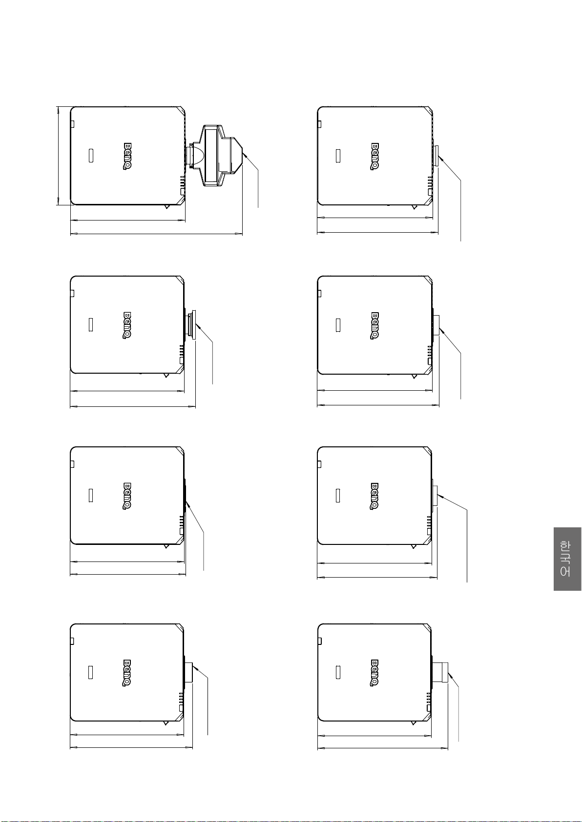
옵션 렌즈 크기
옵션 렌즈 (UST: LSIST4) 옵션 렌즈 ( 광각 고정 : LSIST3)
500
UST LENS
WIDE FIX LENS
582.80
872.5
옵션 렌즈 (UWZ: LSIST2)
582.80
639.4
옵션 렌즈 (STD: LSISD)
582.80
610.16
옵션 렌즈 ( 광각 : LSIST1)
UWZ LENS
WIDE LENS
582.8
616.5
옵션 렌즈 ( 세미 : LSILT1)
582.80
590.7
옵션 렌즈 ( 롱 1: LSILT2)
582.80
626.7
STD LENS
LONG 1 LENS
SEMI LONG LENS
한국어
582.80
609.90
옵션 렌즈 ( 롱 2: LSILT3)
LONG2 LENS
582.80
667.3
95

LED 표시등
표시등 메시지
프로젝터에서 설치 또는 시스템 오류로 인해 발생한 문제에 관해 사용자에게 알리는 데 몇
가지 표시등 메시지가 사용됩니다 . 프로젝터의 상단 덮개에 있는 LED 가 아래 그림에 나와
있습니다 .
TEMP( 온도 ) LED
LED 디스플레이 프로젝터 상태 작동 팁
꺼짐 정상 상태
깜박임 빨간색 과열 오류
가까운 공인 대리점이나 서비스 센터에
문의하십시오 .
LIGHT SOURCE( 광원 ) LED
LED 디스플레이 프로젝터 상태 작동 팁
꺼짐 광원이 꺼졌음
녹색 프로젝터를 켜는 중
깜박임
켜짐
빨강 (6 사이클 ) 광원 수명이 끝남 현지 서비스 센터에 전화하십시오 .
빨간색 광원 문제 현지 서비스 센터에 전화하십시오 .
녹색 광원이 켜졌음
한국어
STATUS( 상태 ) LED 표시등
LED 디스플레이 프로젝터 상태 작동 팁
닫기 보통
상단 덮개가 잘 조립되었는지 또는 렌즈가 잘
깜박임
표시등 켜짐 빨간색 시스템 오류 현지 서비스 센터에 문의하십시오 .
빨강 (1 회 ) 안전 스위치 오류
빨간색 (4 회 ) 팬 오류 현지 서비스 센터에 문의하십시오 .
설치되었는지 여부를 확인하십시오 . 문제가
지속되면 현지 서비스 센터에 문의하십시오 .
96

POWER( 전원 ) LED 표시등
LED 디스플레이 프로젝터 상태 작동 팁
닫기 AC 전원 꺼짐 AC 전원을 확인하고 프로젝터를 켜십시오 .
프로젝터 즉시 사용
가능 .
프로젝터가 영사를 시작할 때까지 기다리십시오 .
프로젝터의 전원을 켜려면 리모컨에서 ON 키를
누르거나 제어판에서 전원 키를 누르십시오 .
깜박임
표시등 켜짐
녹색
주황 프로젝터 냉각 중
빨간색 대기모드
녹색 프로젝터 전원 켜짐
한국어
97

目錄
注意 ........................................................................................................99
通風圖解
散熱孔需求
電壓開關
安裝過程的注意事項
..........................................................................................................................
......................................................................................................................
..........................................................................................................................
.......................................................................................................
99
99
100
100
產品資訊 ................................................................................................. 101
包裝內容
投影機規格
端子 .................................................................................................................................102
遙控器 .............................................................................................................................103
遙控器 ID 設定
..........................................................................................................................
......................................................................................................................
................................................................................................................
101
101
103
安裝 ........................................................................................................104
鏡頭規格
投影桌 .............................................................................................................................105
鏡頭偏移 ..........................................................................................................................107
安裝位置 ..........................................................................................................................108
..........................................................................................................................
104
尺寸 ........................................................................................................109
外殼尺寸
天花板安裝孔尺寸
天花板安裝尺寸 (CMG6) ...............................................................................................110
選購鏡頭尺寸 ..................................................................................................................111
..........................................................................................................................
...........................................................................................................
109
109
LED 指示燈 ............................................................................................ 112
繁體中文
如需最新版使用手冊 / 安裝指南,請造訪下列網站。
http://business-display.benq.com/
10/12/18
98

注意
通風圖解
進氣口
進氣口
出風口
散熱孔需求
為使投影機達到適當的通風效果,請務必如下圖所示使投影機周圍保留一些空間:
11.8 英吋 /
30 公分
或更大
19.7 英吋 / 50 公分
或更大
HDBaseT / LAN
3D Sync Out
RGB IN
RS-232 USBTRIGGER
CENTER
AUTO
POWER
SHUTTER
LENS
INPUT
DVI-D
Display Port
HDMI
R/Pr G/Y B/Pb
HV
RGB OUT
WIRE
MENU EXIT
SYNC ASPECT
FOCUS
ZOOM
LENS
SHIFT
11.8 英吋 /
30 公分
或更大
19.7 英吋 / 50 公分
或更大
繁體中文
99

最小
11.8 英吋 / 30 公分
最小
19.7 英吋 / 50 公分
MENU EXIT
SHIFT
LENS
FOCUS
ZOOM
INPUT
SYNC ASPECT
LENS
SHUTTER
POWER
AUTO
CENTER
Display PortDVI-D
RS-232 USBTRIGGER
WIRE
R/Pr G/YB/Pb
RGB IN
HV
RGB OUT
HDMI
HDBaseT / LAN
3D Sync Out
電壓開關
請確認在電壓開關中選擇投影機使用地區正確的電壓。
注意:
預設設定是 230V。
最小
39.3 英吋 / 100 公分
安裝過程的注意事項
• 更換或拆卸鏡頭時,請先關閉投影機,否則會導致投影機不經過正常程序而立即關閉。
繁體中文
• 為了避免損壞 DLP 晶片,請勿將高功率雷射光束對準投影鏡頭。
100
 Loading...