

Page 1
1
Applicable Country & Regions: Global
Service Manual for BenQ:
Version: 2nd
Date: 6-22-2016
Notice:
For RO to input specific “Legal Requirement” in specific NS regarding to responsibility and
liability statements.
Please check BenQ’s eSupport web site, http://esupport.benq.com, to ensure that you have
the most recent version of this manual.
Second Edition (June. 2016)
©
Copyright BenQ Corporation 2016. All Right Reserved.
GW2470H
9H.LDMLA.TB*
Applicable for All Regions
Page 2

2
Content Index
Abbreviations & Acronyms ........................................................................................................................................ 3
1. About this Manual ................................................................................................................................................... 5
1.1 Important ............................................................................................................................................................ 5
1.2 Trademark .......................................................................................................................................................... 5
2. Introduction ............................................................................................................................................................. 6
2.1 RoHS (2002/95/EC) Requirements – Applied to all countries require RoHS. .................................................... 6
2.2 Safety Warning and Notice ................................................................................................................................. 6
2.3 Compliance Statement ....................................................................................................................................... 7
3. General Description ................................................................................................................................................ 8
4. Related service information................................................................................................................................... 8
5. Product Overview ................................................................................................................................................... 9
5.1 Monitor Specifications ........................................................................................................................................ 9
5.2 Panel Inspection Specification.......................................................................................................................... 15
Level 1 Cosmetic / Appearance / Alignment Service ............................................................................................ 22
Visual Inspection & Cleaning .................................................................................................................................. 22
Software/Firmware Upgrade Process .................................................................................................................... 22
Factory mode ........................................................................................................................................................ 29
Adjustment / Alignment Procedure ......................................................................................................................... 37
Level 2 Circuit Board or Standard Parts Replace ment ........................................................................................ 61
Product Exploded View .......................................................................................................................................... 61
Six Angles’ View ..................................................................................................................................................... 63
Product Disassembly/Assembly ............................................................................................................................. 64
Troubleshooting ...................................................................................................................................................... 74
Appendix 1 – Screw List / Torque ........................................................................................................................... 80
Page 3

3
Abbreviations & Acronyms
A
ADC
Analog to Digital Converter
AFC
Automatic Frequency Control: control signal used to tune to the correct frequency
B
BenQ
BenQ Corporation
BTSC
Broadcast Television System Committee
C
CPU
Central Process Unit
CVBS
Composite Video Blanking and Synchronization
D
DLP
Digital Light Processing / Texas Instruments®
DMD
Digital Micro mirror Device
DRAM
Dynamic RAM
DVI
Digital Visual Interface
DVI-D
Digital Visual Interface-digital
DVI-I
Digital Visual Interface-Integrated
E
EEPROM
Electrically Erasable and Programmable Read Only Memory
F
FLASH
FLASH memory
G
G-TXT
Green Teletext
H
HDMI
High Definition Multimedia Interface, digital audio and video interface
HP
Head Phone
I
I2C
Integrated IC bus
L
LED
Light Emitting Diode
LVDS
Low Voltage Differential Signal, data transmission system for high
M
MOSFET
Metal Oxide Semiconductor Field Effect Transistor
Page 4

4
N
NC
Not Connected
NVM
Non Volatile Memory: IC containing TV related data (for example, options)
O OSD
On Screen Display
P
PC
Personal Computer
PCB
Printed Circuit Board (or PWB)
R
RC
Remote Control transmitter
RGB
Red, Green and Blue. The primary color signals for TV. By mixing levels of R, G
and B, all colors (Y/C) are
ROM
Read Only Memory
S SDA
Data signal on I2C bus
SDRAM
Synchronous DRAM
SW
Sub Woofer / Software
T
THD
Total Harmonic Distortion
V VGA
Video Graphics Array
Y
YPbPr
Component video (Y= Luminance, Pb / Pr= Color difference signals B-Y and R-Y,
other amplitudes w.r.t. to YUV)
Y/C
Video related signals: Y consists of luminance signal, blanking level and sync; C
consists of color signal.
Page 5

5
1. About this Manual
The purpose of Service Manual is to provide a guide line to engineers to repair different models. The appearance
and capability is introduced in this Service Manual. It is better for repair engineer to have a rough idea of this
model through reading the Service Manual. Please do pay attention to the item part of the disassembly when
repair the machine and also do the protection of panel any time. When repairing the circuit board, please follow
the requirement of RoHS and refer to the circuit diagram and repairing process that attached in the Service
Manual. The method of firmware updated, the way of using the menu and some information that may be used
when repairing are also attached in the Service Manual that provide repair engineer various choice.
1.1 Important
Only trained service personnel who are familiar with this BenQ Product shall perform service or maintenance to it.
Before performing any maintenance or service, the engineer MUST read the “Important Safety Information”.
1.2 Trademark
Page 6

6
2. Introduction
This section contains general service information, please read through carefully. It should be stored for easy
access place.
2.1 RoHS (2002/95/EC) Requirements – Applied to all countries require RoHS.
The RoHS (Restriction of Hazardous Substance in Electrical and Electronic Equipment Directive) is a legal
requirement by EU (European Union) for the global electronics industry which sold in EU and some counties also
require this requirement. Any electrical and electronics products launched in the market after June 2006 should
meet this RoHS requirements. Products launched in the market before June 2006 are not required to compliant
with RoHS parts. If the original parts are not RoHS complaints, the replacement parts can be non ROHS
complaints, but if the original parts are RoHS compliant, the replacement parts MUST be RoHS complaints.
If the product service or maintenance require replacing any parts, please confirming the RoHS requirement before
replace them.
2.2 Safety Warning and Notice
Installation
1. Do not use your monitor under any of the following environmental conditions:
Extremely high or low temperature, or in direct sunlight
Dusty places
Highly humid, exposed to rain, or close to water
Exposed to vibrations or impacts in places such as cars, buses, trains, and other rail vehicles
Near heating appliances such as radiators, heaters, fuel stoves, and other heat-generating items
(including audio amplifiers)
An enclosed place (such as a closet or bookcase) without appropriate ventilation
An uneven or sloping surface
Exposed to chemical substances or smoke
2. Do not block vents and openings by clothes or curtains.
3. Carry the monitor carefully.
4. Do not place the monitor face down on the floor or a desk surface directly. Otherwise, scratches on the panel
surface may occur.
5. Do not place heavy loads on the monitor to avoid possible personal injury or damage to the monitor.
6. Ensure that children do not hang or climb onto the monitor.
7. Keep all packing bags out of reach of children.
Page 7

7
Operation
1. To protect your eyesight, please refer to the user manual to set the optimal screen resolution and the viewing
distance.
2. To reduce eye fatigue, take a break on a regular basis while using the monitor.
Avoid taking either one of the following actions for a long time. Otherwise, burn marks may occur.
Use the monitor in the aspect ratio of 16:9.
Place a still image (such as an OSD menu, fixed text or image) on the screen.
3. To avoid possible damage to the monitor, do not touch the monitor panel by hand, pen, or any other sharp
objects.
4. Excessively frequent plug and unplug of video connectors (D-sub / HDMI) may cause damage to the monitor.
5. This monitor is designed mainly for personal use. If you want to use the monitor in a public place or a harsh
environment, contact your nearest BenQ service center for assistance.
6. To avoid possible electric shock, do not dissemble or repair the monitor.
7. If a bad smell or an abnormal sound appears to come from the monitor, contact your nearest BenQ service
center for assistance immediately.
Cleaning
1. Ensure that the power is unplugged before cleaning your monitor
2. Use a monitor cleaner and a soft cloth to clean your monitor.
3. Do not use solvents such as alcohol to clean your monitor.
Power
1. To avoid possible damage to the monitor, do not use it in a region where power supply is unstable.
2. Ensure that the power cord is connected to a grounded power outlet before turning on the monitor.
3. Use only the power cord provided by BenQ.
4. Never use a power cord that appears to be damaged or frayed.
5. To avoid possible danger, observe the total electric load when using the monitor with a (multi-outlet)
extension cord.
6. Always turn off the monitor before unplugging the power cord.
2.3 Compliance Statement
Caution: This Optical Storage Product contains a Laser device. Refer to the product specifications and your local
Laser Safety Compliance Requirements.
Page 8

8
3. General Description
This new LED (light-emitting diode) monitor BenQ GW2470H offers numerous features and functions, for
example:
Panel Type: AMVA+ LED
Minimal space requirements thanks to slim casing
Optimum ergonomic characteristics (totally distortion-free, excellent picture definition and color purity right into
the corners)
Contrast ratio 3000:1(Type), 20M:1 (DCR), brightness 250nits
MAX. resolution (1920X1080)
Presentation of up to 16.7 M colors (in conjunction with an appropriate graphics card)
Automatic scanning of horizontal frequencies from 30 to 83 kHz and refresh rates (vertical frequencies) from
50 to 76 Hz (absolutely flicker-free)
Digital screen controller with microprocessor for storing 8 different display modes
Freely adjustable color alignment for matching the screen colors to the colors of various input and output
devices
Convenient operation via integrated OSD (On-Screen-Display) menu
VESA-DDC compatibility
Plug & play capability
Power management for reducing power consumption when the computer is not in use
This operating manual contains important information you require to start up and run your LED monitor.
This specification defines the requirements for the 24″ MICROPROCESSOR based Multi-mode supported high
resolution color LED monitor. The monitor can be directly connected to general 15-pin VGA connector and 19-pin
HDMI connector. Also support VESA DPMS power management and plug & play function.
Additional information
Due to the nature of Liquid Crystal Display (LCD) technology, the picture resolution is always fixed. For the best
display performance, please set the display resolution to 1920X1080 pixels with an aspect ratio of 16:9. This is
called “Native Resolution” or maximal resolution - that is, the clearest picture. Lower resolutions are displayed on
a full screen through an interpolation circuit. Image blurring across pixel boundaries can occur with the
interpolated resolution depending upon the image type and its initial resolution.
4. Related service information
This Service Manual contains general information. There are 2 levels of service:
Level 1: Cosmetic / Appearance / Alignment Service
Level 2: Circuit Board or Standard Parts Replacement
Service Web Site
eSupport Website:
BenQer: http://esupport.benq.com/v2
ASP: http://esupport.benq.com/
Page 9
9
5. Product Overview
5.1 Monitor Specifications
GW2470H
D-sub + HDMI 1.4*2
Panel /
Display
Panel Type (TN / VA / IPS)
AMVA+ LED
Panel Model
AUO M238HVN01.0 (SNB)
Panel Size
23.8"(16:9)
Display Area
527.04(H)mm x 296.46(V)mm
Max. Resolution
1920x1080
Pixel Pitch
274.5(H) um x 274.5(V) um
Brightness (Typ.)
250
Contrast Ratio (Typ.) / DCR (Min.)
3000:1 / 20M:1
Viewing Angle (H/V), CR≧10
178/178
Display Colors
16.7million
Response Time
12ms
GtG response Time
4ms
Color space
72% NTSC
Panel maker
AUO
Video
BenQ Senseye
TM
Technology
Yes
Picture mode
Standard / Low Blue Light / Movie / Game / Photo /
s-RGB / ECO / User
Color Temperature Selection
Normal (6500°K) / Reddish (5700°K) / Bluish (9300°K)
/ User Mode
Hor. Frequency (KHz)
30kHz~83KHz
Ver. Frequency (Hz)
50Hz~76Hz
Video Bandwidth (MHz)
205MHz
Audio
Speakers (built-in)
N/A
Audio Mode
N/A
Volume
Yes
Mute
Yes
Input/Output
PC Video Input(VGA)
Yes
DVI Iput
NA
HDMI Input
Yes x2
Audio Line In
NA
Headphone Jack
Yes
Power Supply
Voltage Rating
100-240V
Power-On Mode
35 W
Standby Mode
<0.5W
Power Off Mode
<0.5W
Mechanical
Design
Chassis Colors
Follow ID Artwork
Carton
Brown CTN
Power LED
Green (ON)/ Amber (Standby)
Page 10
10
Tilt (Up / Down)
-5~20
Kensington Lock
Yes
MNT without stand
3.45KG, L:553mm*:W:50.5mm*H:329.4mm
Multi-language
Support
OSD
17 Languages (English / Francais / Deutsch / Italiano /
Espanol / Polish / Czech / Hungarian /
Serbo-croatian / Romanian / Netherlands / Russian /
Swedish / Protuguese / Japanese / Chinese /
S-Chinese)
Other feature
MHL
NA
Win 7/8/8.1
Yes
Mac compatible
NA
SRGB Pro
Yes
HDMI Color Range Select
Yes
Component color Space select
Yes
Gamma Select
5 steps(2.2~3.0)
Super resolution
NA
Smart focus
NA
Dynamic Power Saving
Yes
Display Mode
Full / Aspect Ratio
On-line Gamma calibration
NA
DC Dimmer
Yes
Low Blue Light+
NA
Low Blue Light
Yes
Accessories
Bundle
Refer to sku list
Label
OSD Low Blue Light label
N/A
OSD UI
New UI
Follow BenQ UI
Regulation
Approvals
Regulation Approvals
See RR table
Others
Bundle Software
NA
Page 11
11
5.1.1 Certification
Region
Country
Certification
Level
Apply
by
BenQ
Apply by
Vendor
Sample
Request
Document
Type
Standard
BenQ
Information
& Request
Document provide
Target
Date
Actual
Date
BQA
USA
EPEAT
Silver Y
Certificate
IEEE
1680.1
2015/06/
26
BQA
USA
EPEAT
Silver Y
Reports
IEEE
1680.1
2015/06/
26
BQA
USA &
Canada
cTUVus
Y
Certificate
UL60950-
1& CSA
C22.2 No.
60950-1-0
7
For both US
and Canada
use.
2015/06/
26
BQA
USA &
Canada
FCC and IC
Y
DOC
FCC part
15B;
ICES-003
2015/06/
26
BQA
USA &
Canada
FCC and IC
Y
Reports
FCC part
15B;
ICES-003
2015/06/
26
BQC
China
CCC
Y
Certificate
GB4943,
GB9254,
GB17625.
1
Maker:
BENQ
2015/06/
26
BQC
China
CCC
Y
Printing
Permissio
n
GB4943,
GB9254,
GB17625.
1
Maker:
BENQ
2015/06/
26
BQC
China
CCC
Y
Reports
GB4943,
GB9254,
GB17625.
1
Maker:
BENQ
2015/06/
26
BQC
China
China
Energy
Label
Y
Certificate
GB 21520-
2015/06/
26
BQC
China
China
Energy
Label
Y
Reports
GB 21520-
2015/06/
26
BQE
EU
CE
Y
DOC
EN55022;
EN55024
2015/06/
26
BQE
EU
CE
Y
DOI
EN55022;
EN55024
2015/06/
26
BQE
EU
CE
Y
Reports
EN55022;
EN55024
2015/06/
26
BQE
EU
ErP
Y
Reports
2005/32/E
C,
2009/125/
EC, EC No
1275-2008
and its
implement
ation
measurem
ents.
2015/06/
26
BQE
EU
REACH
Y
Evidence
EC No.
1907/2006
& SVHC
lists, No.
552/2009
2015/06/
26
BQE
EU
WEEE
Y
Reports
2002/96/E
C and its
amendme
nts
2015/06/
26
BQE
German
y
Bauart
Y
Certificate
EN60950-
1
2015/06/
26
BQE
Germany Energy
Efficiency
Y
Reports
No
1062/2010
For BQE's
requirement
2015/06/
26
Page 12
12
Label
BQE
German
y
ISO9241-30
7
Y
Certificate
ISO9241-3
07
2015/06/
26
BQE
German
y
ISO9241-30
7
Y
Reports
ISO9241-3
07
2015/06/
26
BQE
German
y
MPRII
Y
Certificate
MPR II:
MPR
1990: 8 /
MPR1990:
10
2015/06/
26
BQE
German
y
MPRII
Y
Reports
MPR II:
MPR
1990: 8 /
MPR1990:
10
2015/06/
26
BQE
Russia,
Belarus
CU
Y
Certificate
2015/06/
26
BQE
Ukraine
Safety &
EMC DoC
Y
Certificate
IEC
60950-1
2015/06/
26
BQE
Ukraine
UkrSEPRO
Y
Certificate
CISPR22;
CISPR24;
IEC60950-
1
2015/06/
26
BQL
Mexico
Mexico
Energy
Label
Y
Certificate
Law for
Sustainabl
e Energy
Apply by SI
directly
2015/06/
26
BQL
Mexico
Mexico
Energy
Label
Y
Reports
Law for
Sustainabl
e Energy
Apply by SI
directly
2015/06/
26
BQL
Mexico
NOM
Y
Certificate
IEC
60950-1
2015/06/
26
BQP
Australia
MEPS
Y
Certificate
AN/NZS
5815.2 :
2013
2015/06/
26
BQP
Australia
MEPS
Y
Reports
AN/NZS
5815.2 :
2013
2015/06/
26
BQP
Australia
& New
Zealand
RCM
Y
DOC
AS/NZS
CISPR
22 ;
AS/NZS
60950.1
BQP
Australia
& New
Zealand
RCM
Y
Reports
AS/NZS
CISPR
22 ;
AS/NZS
60950.1
BQP
India
E-waste(WE
EE)
Y
Reports
India
E-waste
2015/06/
26
BQP
Japan
PC3R
Y
Evidence
PC Green
Label
System
2015/06/
26
BQP
Japan
PSE
Y
DOC
J60950-1,
J55022
For model
with HDMI
2015/06/
26
BQP
Japan
VCCI
Y
Certificate
V-3/V-4,
J55022
Please also
list J55022
2015/06/
26
BQP
Japan
VCCI
Y
Reports
V-3/V-4,
J55022
Please also
list J55022
2015/06/
26
BQP
Kazakhs
tan
CU
Y
Certificate
2015/06/
26
Page 13

13
BQP
Korea
e-Standby
Y
Certificate
Ministry of
Knowledg
e
Economy
Notificatio
n No.
2008-116
2015/06/
26
BQP
Korea
e-Standby
Y
Reports
Ministry of
Knowledg
e
Economy
Notificatio
n No.
2008-116
2015/06/
26
BQP
Korea
KC
Y
Certificate
K60950-1
For safety
approval
2015/06/
26
BQP
Korea
KCC
Y
Certificate
KN22,
KN24,
K00022
(CISPR22)
, K00024
(CISPR24)
2015/06/
26
BQP
Korea
KCC
Y
Reports
KN22,
KN24,
K00022
(CISPR22)
, K00024
(CISPR24)
2015/06/
26
BQP
Kuwait
KUCAS
Y
Certificate
IEC
60950-1
2015/06/
26
BQP
Saudi
Arabia
SASO
Y
Certificate
IEC
60950-1
2015/06/
26
BQP
Singapo
re
PSB
Y
Certificate
IEC
60950-1
2015/06/
26
BQP
Singapo
re
PSB
Y
Evidence
IEC
60950-1
2015/06/
26
BQP
Taiwan
BSMI
Y
Authorizati
on
CNS1433
6;
CNS1343
8
2015/06/
26
BQP
Taiwan
BSMI
Y
Certificate
CNS1433
6;
CNS1343
8
2015/06/
26
BQP
Taiwan
BSMI
Y
Reports
CNS1433
6;
CNS1343
8
2015/06/
26
BQP
Taiwan
Taiwan
Energy
Label
Y
Certificate
2015/06/
26
BQP
Taiwan
Taiwan
Energy
Label
Y
Reports
2015/06/
26
BQP
Turkey
CE
Y
DOC
EN55022;
EN55024
2015/06/
26
BQP
Turkey
CE
Y
DOI
EN55022;
EN55024
2015/06/
26
BQP
Turkey
CE
Y
Reports
EN55022;
EN55024
2015/06/
26
Internati
onal
CB
Scheme
CB
Y
Certificate
IEC
60950-1
Includes JP
deviation
2015/06/
26
Internati
onal
CB
Scheme
CB
Y
Reports
IEC
60950-1
Includes JP
deviation
2015/06/
26
Page 14
14
Internati
onal
Internati
onal
Energy Star
Y
Certificate
ENERGY
STAR
Program
Requirem
ents for
Displays
2015/06/
26
Internati
onal
Internati
onal
Energy Star
Y
Reports
ENERGY
STAR
Program
Requirem
ents for
Displays
2015/06/
26
Internati
onal
Internati
onal
RoHS &
BenQ GP
Guideline
Y
Evidence
2011/65/E
U &
SUP-QM-
07-02
2015/06/
26
Internati
onal
Internati
onal
TCO
Y
Certificate
TCO
Certified
Displays 6
2015/06/
26
Page 15
15
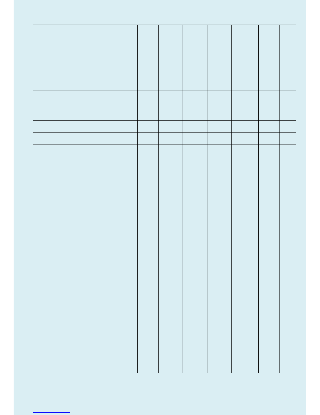
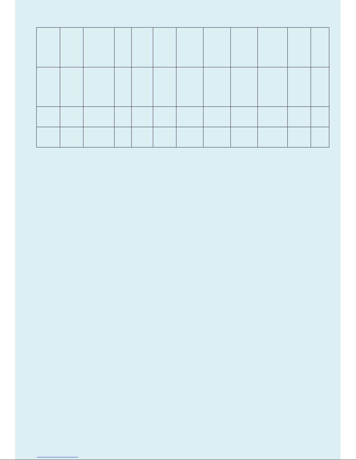
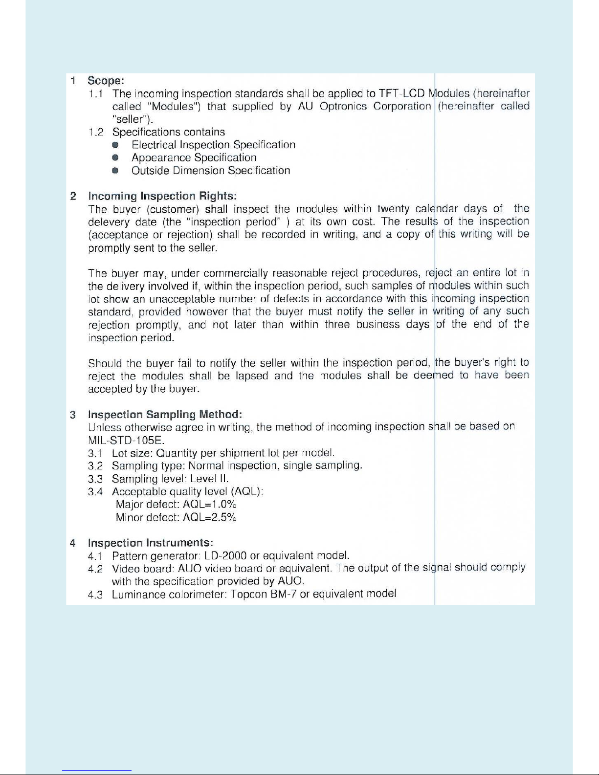
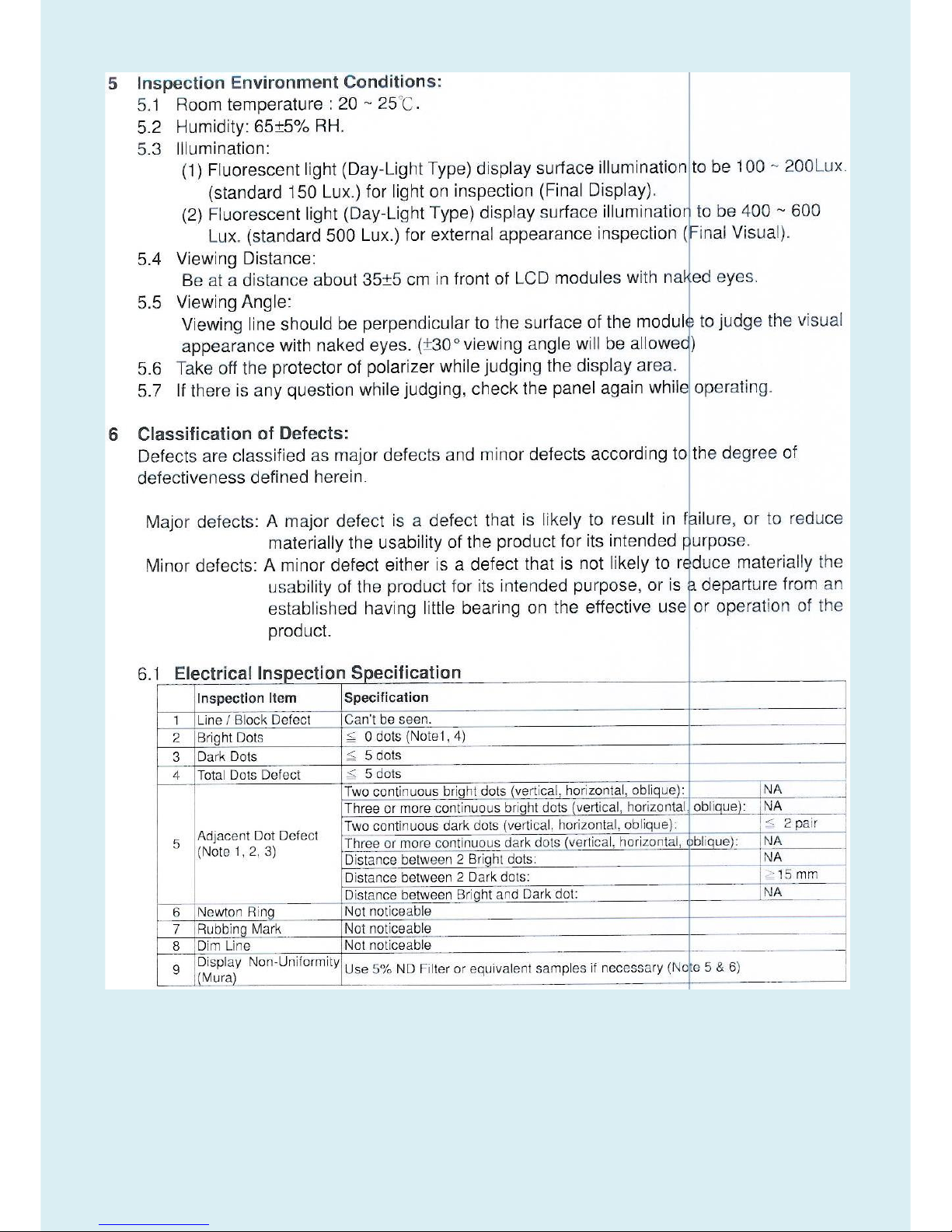
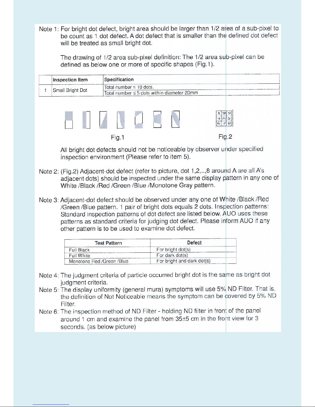
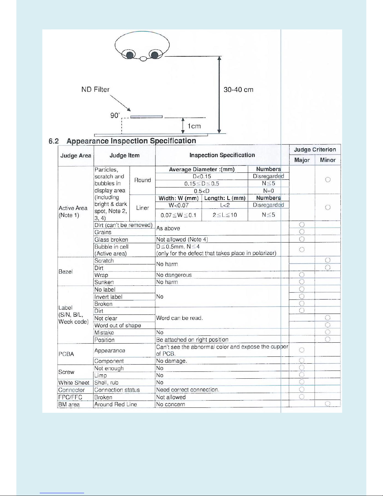
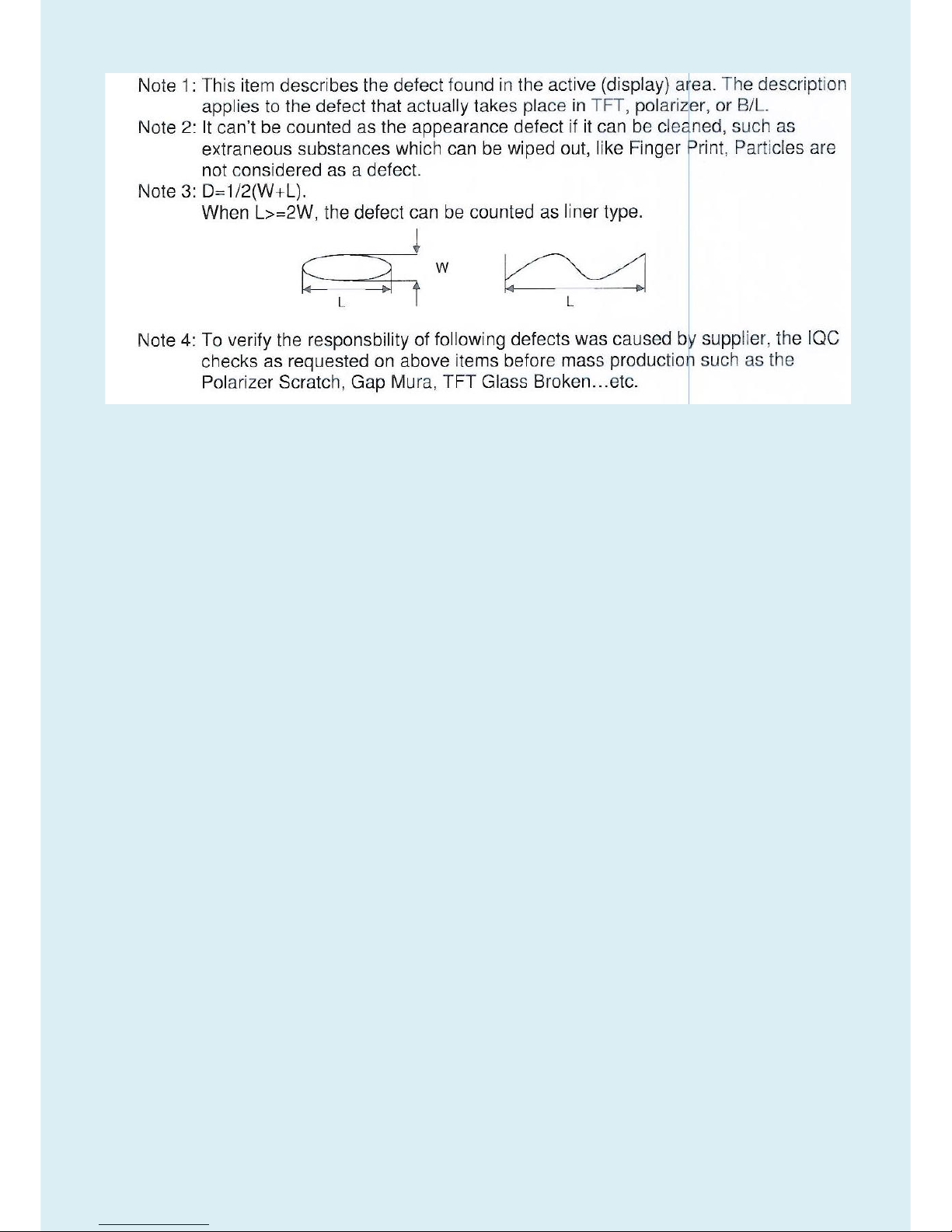
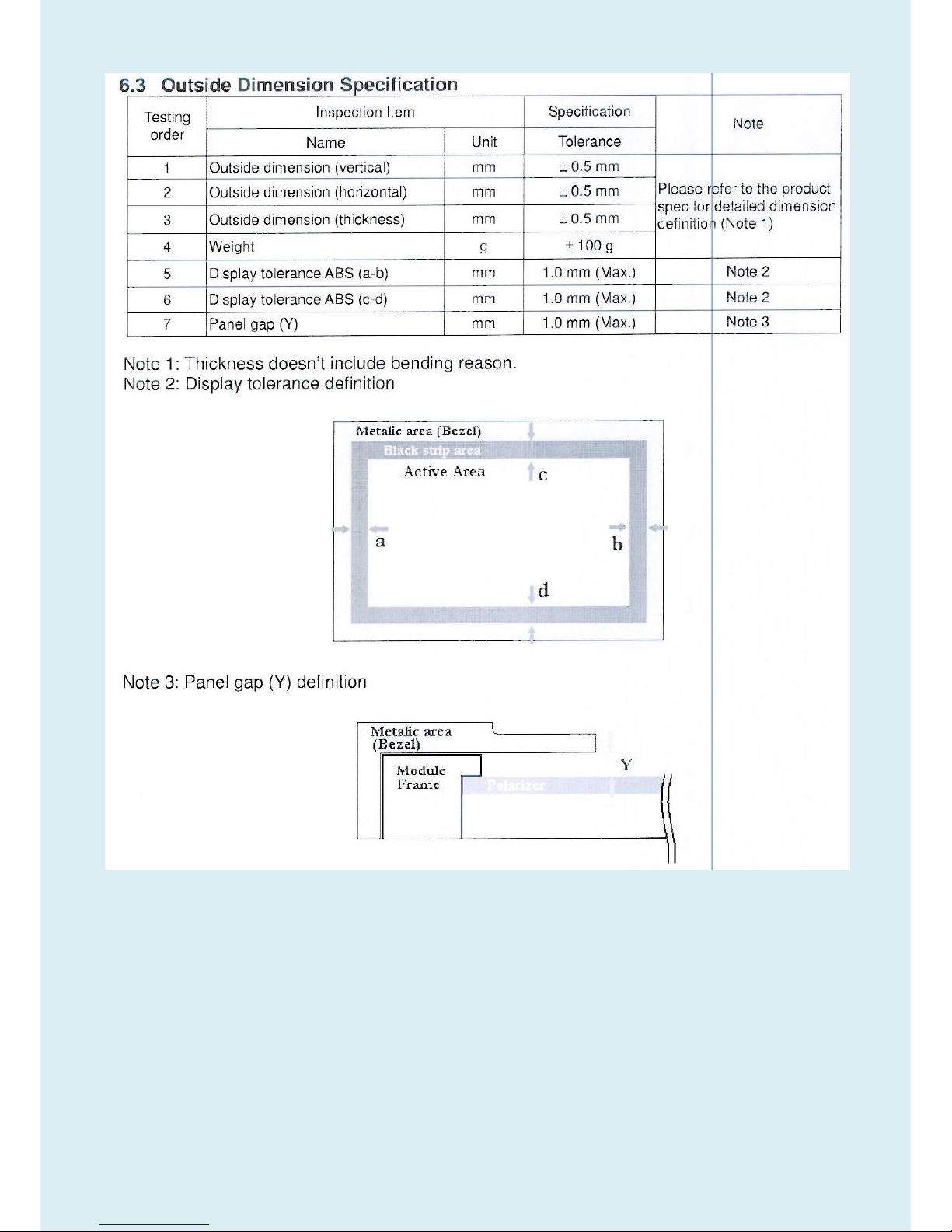
5.2 Panel Inspection Specification
Inspection Standards for LCD Modules
Page 16
16
Page 17
17
Page 18
18
Page 19
19
Page 20
20
Page 21
21
Page 22
22
Level 1 Cosmetic / Appearance / Alignment Service
Visual Inspection & Cleaning
Cleaning Always unplug your monitor from the wall outlet before cleaning. Clean the LED monitor surface with a
lint-free, non-abrasive cloth. Avoid using any liquid, aerosol or glass cleaners.
Slots and openings on the back or top of the cabinet are for ventilation. They must not be blocked or covered.
Your monitor should never be placed near or over a radiator or heat source, or in a built-in installation unless
proper ventilation is provided.
Never push objects or spill liquid of any kind into this product.
Software/Firmware Upgrade Process
Upgrade by 715GT089-B
F/W Upgrade SOP for TSUMO88CDT9
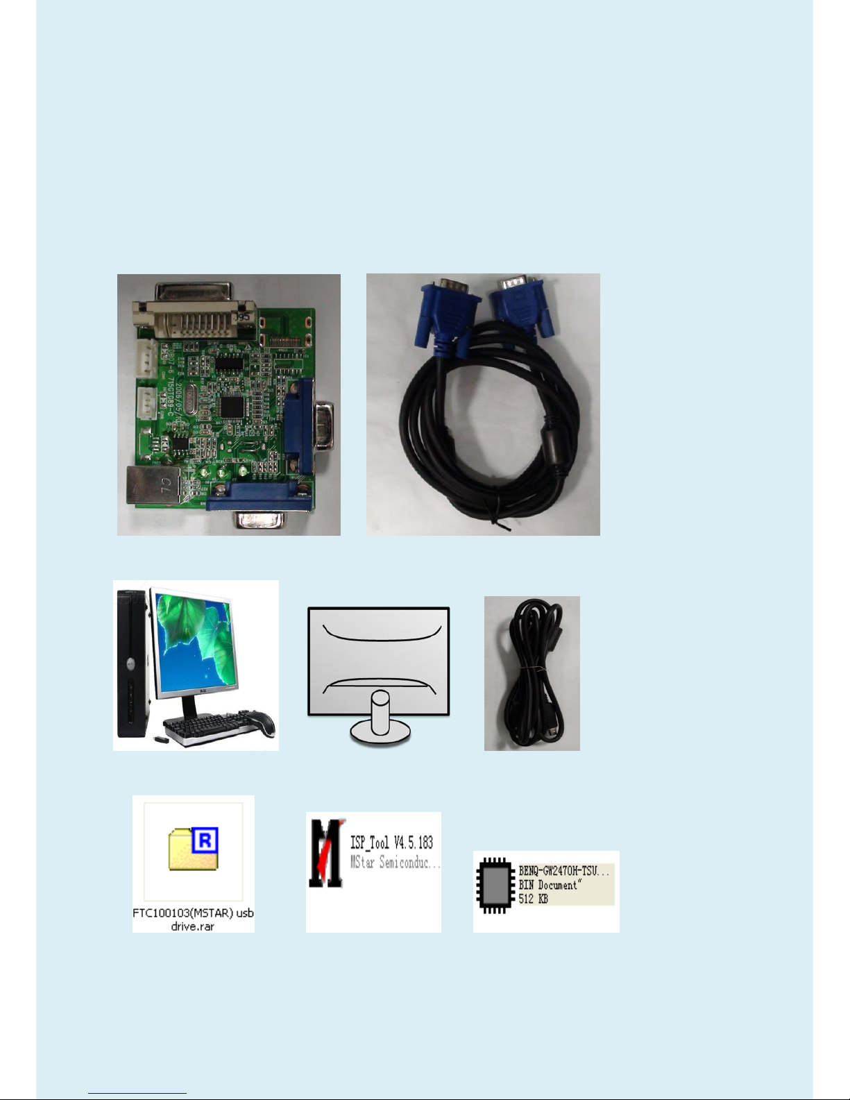
1.Materials list
ISP JIG: 715GT089-B/C VGA cable
TPV P/N: 089G728 GAA DB
PC Monitor USB cable
TPV P/N: 089G1758 X
USB port driver ISP tool: V4.5.183 New F/W
Page 23
23
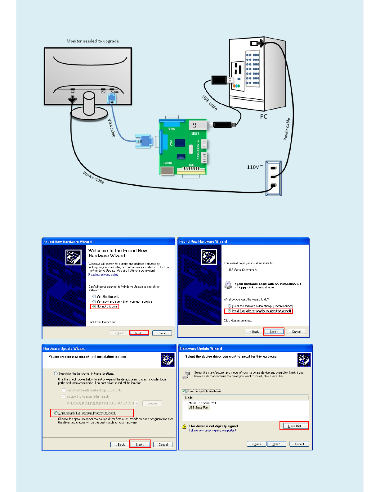
2.Connection
3.Install USB driver.
3.1. When insert the USB cable to PC USB port, will pop up a Hardware Wizard to help you
install the USB driver if you use this ISP board first time. You can install it successfully as the
below instruction step by step.
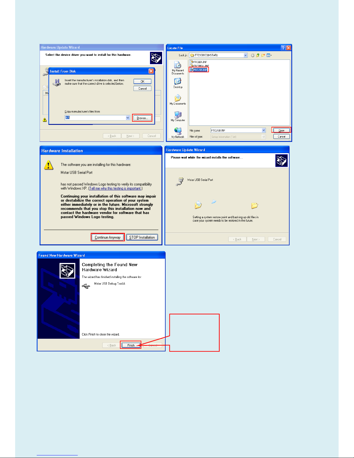
Remark: The USB driver files path: (e.g: D:\FTC100103(Mstar)\FTCUSB.INF)
Page 24
24
Click “Finish” to
complete the
USB serial port
driver
installation.
Page 25

25
4. Update the Software.
4.1. Double-click to run the ISP tool.
4.2. Connect to the monitor. Click “Connect”. If the tool communicate with monitor successfully,
the tool will detect the flash type of monitor.
Page 26

26
4.3. Load the F/W you want to upgrade.
4.4. Set the restore address.
(1)The monitor has DVI port, you need to set restore address for HDCP key to avoid re-program HDCP key.
HDCP KEY Start Address 07F000 (4KB)
Page 27

27
4.5. Set parameter in “Auto” window. If you have set “Restore address”, please tick “Restore
Data”.
4.6.Processing of upgrade. After clicking “Run”, the tool start to program. It is forbided to power
off monitor or switch off connection during programming.
4.7.Successful upgrade. When upgrade successful, there will be green Pass letter appearing.
5. Check the FW version after upgrade.
5.1. Verify the software version and turn off burn in mode.
(1)Connect source to monitor, and turn it on.
(2)DC off the monitor and press the “menu” key and DC on the monitor until the screen
lights, release the “menu”. Then press “menu” again, will pop up below image.
Page 28

28
(3) Service Page and Verify the software version
Page 29

29
5.2. Do Reset All in user menu.
5.3 The way to open BenQ factory menu
(1)Connect signal source and power cable to monitor and DC off it.
(2) Press “Enter” key and “Exit” key as below figure at the same time and then Press “Power “ Key to turn
on the monitor. When the screen lights, release the buttons and then press “Exit” key to open below factory
menu.
Factory mode
Page 30

30
6. Troubleshooting.
6.1. “Can’t Entry ISP Mode!!” or “Can’t Find the Device Type” Error.
Method: (1) Check the cables and ISP JIG are connected fluently.
(2) Click the “Dis Con” and click “Connect” again.
(3) AC off the monitor for a while and retry it.
(4)Change ISP JIG or cable.
(5)Change PC.
6.2. Erase Error(Check the tool version or the speed seting.)
Page 31

31
Page 32

32
Upgrade by 715GT034-B
EDID writing SOP by VGA single port
LPT cable (male to male) VGA cable 12V DC adapter
TPV P/N: N/A TPV P/N: 089G728 GAA DB TPV P/N: ADPC12416BEP
ISP JIG: 715GT034-B PC Monitor
LPT port driver ISP tool EDID
Page 33

33
2. Connection(DC on the monitor)
3. Install LPT driver.
3.1. Double click the icon to install the driver. Restart PC after installation.
4. Prepare the EDID written.
4.1. Change the EDID files name as below rule.
VGA EDID WA.dat
HDMI EDID WH.dat HDMI2 EDID WH2.dat
4.2. Copy these files to one folder named as BENQ GW2470 which must contains “config.ini” file.
4.3. Copy BENQ GW2470 to DDC folder and put DDC and ISP tool together.
Page 34

34
5. Run the ISP tool
5.1. Double-click the icon to open the tool.
5.2. Select the EDID folder.
Page 35

35
5.3. Load EDID successful.
5.4 Tick the “Only connect VGA”, and “Write SN” then click “Debug Imformayion”.
Page 36

36
5.5 type in the date and the 13 digit S/N.
5.6. Start to writing. Click “write EDID” to start writing. When The green “PASS” appear, the process is finished.
6. Troubleshooting.
6.1. Can’t write!
(1) AC on the monitor and turn on it.(Restart the monitor)
(2)Take apart the monitor and connect the 7pin of EEPROM to GND to diable write protection then write EDID
one by one.
(3) Set the Burn in on last to try again.
Page 37

37
Adjustment / Alignment Procedure
The Control Panel
Page 38

38
Basic menu operation
All OSD (On Screen Display) menus can be accessed by the control keys. You can use the OSD menu to adjust
all the settings on your monitor.
1
2
4
3
1. Press any of the control keys.
2. The hot key menu is displayed. The left three controls are custom keys and are designated
for
particular functions.
3. Select (Menu) to access the main menu.
4. In the main menu, follow the icons next to the control keys to make adjustments or
selection.
No.
OSD in hot key
menu
OSD icon
in main
menu
Function
Custom Key 1
• By default, the key is the hot key for Low Blue Light. To
• For Up/Increase adjustment.
Page 39

39
No.
OSD in hot key
menu
OSD icon
in main
menu
Function
Custom Key 2
• By default, the key is the hot key for Input.
• For Down/Decrease adjustment.
Custom Key 3
/
• By default, the key is the hot key for Brightness..
• Enters sub menus.
• Selects menu items.
Menu
• Activates the main menu.
• Returns to the previous menu.
Exit
Exits OSD menu.
•
OSD = On Screen Display.
The hot keys only operate while the main menu is not currently displaying. Hot key displays will
disappear after a few seconds of no key activity.
•
To unlock the OSD controls, press and hold any key for 10 seconds.
Page 40

40
Display menu
Available menu options may vary depending on the input sources, functions and settings. Menu options that are
not available will become grayed out. And keys that are not available will be disabled and the corresponding
OSD icons will disappear. For models without certain functions, their settings and related items will not appear
on the menu.
1. Select (Menu) from the hot key menu.
2.
Use
or
to select Display.
3. Select to go to a sub menu, and then use
or
to select a menu item.
4.
Use
or
to make adjustments, or use to make selection.
5. To return to the previous menu, select .
6. To exit the menu, select .
Item
Function
Range
Auto Adjustment
Optimizes and adjusts the screen settings
automatically for you.
Not applicable to a digital input signal.
Input
Use this to change the input to that appropriate to your
video cable connection type.
• D-Sub
• DVI
• HDMI (for
models with
HDMI inputs)
Page 41

41
Item
Function
Range
H. Position
Adjusts the horizontal position of the screen image.
0 to 100
V. Position
Adjusts the vertical position of the screen image.
0 to 100
Pixel Clock
Adjusts the pixel clock frequency timing to
synchronize with the analog input video signal.
Not applicable to a digital input signal.
0 to 100
Phase
Adjusts the pixel clock phase timing to synchronize with
the analog input video signal.
Not applicable to a digital input signal.
0 to 63
Page 42

42
Picture menu
Available menu options may vary depending on the input sources, functions and settings. Menu options that are
not available will become grayed out. And keys that are not available will be disabled and the corresponding
OSD icons will disappear. For models without certain functions, their settings and related items will not appear
on the menu.
1. Select (Menu) from the hot key menu.
2.
Use
or
to select Picture.
3. Select to go to a sub menu, and then use
or
to select a menu item.
4.
Use
or
to make adjustments, or use to make selection.
5. To return to the previous menu, select .
6. To exit the menu, select .
Item
Function
Range
Brightness
Adjusts the balance between light and dark shades.
0 to 100
Contrast
Adjusts the degree of difference between darkness and
lightness.
0 to 100
Sharpness
Adjusts the clarity and visibility of the edges of the subjects in the
image.
1 to 10
Page 43

43
Item
Function
Range
Gamma
Adjusts the tone luminance. The default value is 3 (the
standard value for Windows).
• 1
• 2
• 3
• 4
• 5
Color
Temperature
Normal
Allows video and still photographs to be viewed with
natural coloring. This is the factory default color.
Bluish
Applies a cool tint to the image and is factory pre-set
to the PC industry standard white color.
Reddish
Applies a warm tint to the image and is factory
pre-set to the news print standard white color.
User
Define
The blend of the Red, Green and Blue primary colors
can be altered to change the color tint of the image.
Go to the succeeding R (red),
G (green), and B (blue) menus to change the
settings.
Decreasing one or more of the colors will reduce
their respective influence on the color tint of the
image. (e.g. if you reduce the Blue level the image
will gradually take on a yellowish tint. If you reduce
Green, the image will become a magenta tint.)
• R (0~100)
• G (0~100)
• B (0~100)
Hue
Adjusts the degree of how we perceive colors.
0 ~ 100
Saturation
Adjusts the purity degree of colors.
0 ~ 100
Reset Color
Resets the custom color settings to the factory defaults.
• YES
• NO
AMA
Improves the gray level response time of the LCD panel.
• OFF
• High
• Premium
Page 44

44
Picture Advanced menu
Available menu options may vary depending on the input sources, functions and settings. Menu options that are
not available will become grayed out. And keys that are not available will be disabled and the corresponding
OSD icons will disappear. For models without certain functions, their settings and related items will not appear on
the menu.
1. Select (Menu) from the hot key menu.
2.
Use
or
to select Picture Advanced.
3. Select to go to a sub menu, and then use
or
to select a menu item.
4.
Use
or
to make adjustments, or use to make selection.
5. To return to the previous menu, select .
6. To exit the menu, select .
Item
Function
Range
Picture
Mode
Select a picture mode that best suits the type of images shown on the
screen.
Standard
For basic PC application.
Low
Blue
Light
Decreases the blue light emitted from the display to reduce
the risk of blue light exposure to your eyes.
The value for each Low Blue Light mode indicates
how much blue light is decreased compared with the
Standard mode.
Page 45

45
Item
Function
Range
Multimedia
For viewing multimedia files.
-30%
Web
Surfing
For web surfing.
-50%
Office
For office works or office environment.
-60%
Reading
For reading e-books or documents.
-70%
Movie
For viewing videos.
Game
For playing video games.
Photo
For viewing still images.
sRGB
For better color matching representation with the
peripheral devices, such as printers, digital cameras, etc.
Eco
For saving electricity with low power consumption by
providing minimum brightness for all running programs.
User
Applies a combination of picture settings defined by
users.
Senseye
Demo
Displays the preview of screen images under the selected mode from
Picture Mode. The screen will be divided into two windows; the left window
demonstrates images of Standard mode, while the right window presents
the images under the specified mode.
• ON
• OFF
Dynamic
Contrast
The function is to automatically detect the distribution of an input visual
signal, and then to create the optimal contrast.
0 to 5
Overscan
Slightly enlarges the input image. Use this feature to hide annoying edge
noise if present around your image.
Available only when the input source is HDMI or D-Sub (VGA
converted from Component).
•
ON
•
OFF
Display
Mode
This feature is provided to allow aspect ratios other than 16:9 to be
displayed without geometric distortion.
The options under Display Mode will be different depending on the
input signal sources.
Depending on your selection of Picture Mode, different Display Mode
option is pre-set. Change the setting if needed.
Full
Scales the input image to fill the screen. Ideal for 16:9
aspect images.
Aspect
The input image is displayed without geometric
distortion filling as much of the display as possible.
Page 46

46
Item
Function
Range
Color
Format
Determines the color space (RGB or YUV) based on the detected video
signal.
You might need to manually set the Color Format if colors shown
on the monitor screen do not display properly.
If the input source is HDMI, color format is not selectable. In other
words,
Color Format is automatically set depending on the input video source.
RGB
• For D-Sub (VGA) input source from PC.
• For DVI input source.
YUV
For D-Sub (Component converted from VGA) input source
from a video device.
HDMI RGB
PC Range
Determines the range of color scales. Select an option that matches the
RGB range setting on the connected HDMI device.
• RGB (0 ~
255)
• RGB (16 ~
235)
Page 47

47
Audio menu (selected models only)
Available menu options may vary depending on the input sources, functions and settings. Menu options that are
not available will become grayed out. And keys that are not available will be disabled and the corresponding OSD
icons will disappear. For models without certain functions, their settings and related items will not appear on the
menu.
1. Select (Menu) from the hot key menu.
2.
Use
or
to select Audio.
3. Select to go to a sub menu, and then use
or
to select a menu item.
4.
Use
or
to make adjustments, or use to make selection.
5. To return to the previous menu, select .
6. To exit the menu, select .
Item
Function
Range
Volume
Adjusts the audio volume.
0 ~ 100
Mute
Mutes the audio input.
• ON
• OFF
Page 48

48
System menu
Available menu options may vary depending on the input sources, functions and settings. Menu options that are
not available will become grayed out. And keys that are not available will be disabled and the corresponding OSD
icons will disappear. For models without certain functions, their settings and related items will not appear on the
menu.
1. Select (Menu) from the hot key menu.
2.
Use
or
to select System.
3. Select to go to a sub menu, and then use
or
to select a menu item.
4.
Use
or
to make adjustments, or use to make selection.
5. To return to the previous menu, select .
6. To exit the menu, select .
Page 49

49
Item
Function
Range
OSD
Settings
Language
Sets the OSD menu language.
The language options displayed on
your OSD may differ from those shown
on the right, depending on the product
supplied in your region.
• English
• Français
• Deutsch
• Italiano
• Español
• Polski
• Česky
• Magyar
• SiCG/BiH/CRO
• Română
• Nederlands
• Русский
• Svenska
• Português
•日本語
•繁體中文
•简体中文
Display
Adjusts the display time of the OSD menu.
• 5 Sec.
Time
• 10 Sec.
• 15 Sec.
• 20 Sec.
• 25 Sec.
• 30 Sec.
OSD Lock
Prevents all the monitor settings from being
accidentally changed. When this function is
activated, the OSD controls and hotkey
operations will be disabled.
To unlock the OSD controls, press and
hold any key for 10 seconds.
Custom Key
1
Sets the function to be accessed by custom ke y 1.
• Picture Mode
• Low Blue Light
• Display Mode
• Brightness
• Contrast
• Auto
Adjustment
• Mute
• Input
Custom Key
2
Sets the function to be accessed by custom ke y 2.
Custom Key
3
Sets the function to be accessed by custom ke y 3.
Page 50

50
Item
Function
Range
DDC/CI
Allows the monitor settings to be set through the software on the
PC.
DDC/CI, short for Display Data Channel/Command
Interface, which was developed by Video
Electronics Standards Association (VESA). DDC/CI
capability allows monitor controls to be sent via the
software for remote diagnostics.
• ON
• OFF
HDMI Auto
Switch
When this function is activated, HDMI port will be in the input
auto select loop. Otherwise, HDMI can only be selected by
input select or by hot key.
• ON
• OFF
Auto Power
Off
Sets the time to power off the monitor automatically in power
saving mode.
• OFF
• 10min.
• 20min.
• 30min.
Resolution
Notice
Sets whether to display the resolution notice of the
recommended resolution when a new input source is
• ON
• OFF
Information
Displays the current monitor property settings.
•
Input
•
Current
Resolution
• Optimum
Resolution
(best with the
monitor)
• Model Name
Reset All
Resets all mode, color and geometry settings to the
factory default values.
• YES
• NO
Page 51

51
Display Timing Table
Note:
P: Preset Mode
NP: None Preset Mode
FS: Fail Save Mode (show “out of range”, but still can see picture)
O: Out of Range (only show “out of range”, without picture)
BenQ
Preferr
ed
Mode
Numb
er
Panel Native Resolution
Reso
lution
Pixel
clock
H-syn
c
V-sync
1280x1024
1366x768
1440x900
1600x900
1680x1050
1920x1080VA Panel
(Piexl clock : 83M)
1920x1080
1920x1080
Gaming 144Hz panel
1920 x 1200
1920x1200(24W)
1920x1080
2560 x 1440
3840 x 2160
(unit:M
Hz)
(unit:K
Hz)
(unit:H
z)
IDF-1 P P P P P FS P P P P P P
P
640x
350
25.18
31.47
70.09
FS
FS
FS
FS
FS O FS
FS
FS
FS
FS
FS
FS
640x
350
31.50
37.86
85.08
NP
NP
NP
NP
NP O NP
NP
NP
NP
NP
NP
NP
640x
400
25.18
31.47
70.09
FS
FS
FS
FS
FS O FS
FS
FS
FS
FS
FS
FS
640x
400
31.5
37.86
85.08
NP
NP
NP
NP
NP P NP
NP
NP
NP
NP
NP
NP
640x
480
30.24
35.00
66.67
DMT-1
P P P P P P P P P P P P P
640x
480
25.17
31.47
59.94
NP
NP
NP
NP
NP O NP
NP
NP
NP
NP
NP
NP
640x
480
31.50
37.86
72.81
DMT-2
P P P P P
FS P P P P P P
P
640x
480
31.50
37.50
75.00
DMT-3
FS
FS
FS
FS
FS O FS
FS
FS
FS
FS
FS
FS
640x
480
36.00
43.27
85.01
NP
NP
NP
NP
NP
NP
NP
NP
NP
NP
NP
NP
NP
640x
500
25.25
31.00
57.76
IDF-2 P P P P P FS P P P P P P
P
720x
400
28.32
31.47
70.08
FS
FS
FS
FS
FS O FS
FS
FS
FS
FS
FS
FS
720x
400
35.5
37.93
85.04
Page 52

52
P P P P P
FS P P P P P P
P
832x
624
57.27
49.71
74.53
BenQ
NP
NP
NP
NP
NP
NP
NP
NP
NP NP
NP
NP
800x
480
29.5
29.74
59.476
NP
NP
NP
NP
NP P NP
NP
NP
NP
NP
NP
NP
800x
600
36.00
35.16
56.25
DMT-4
P P P P P P P P P P P P P
800x
600
40.00
37.88
60.32
NP
NP
NP
NP
NP O NP
NP
NP
NP
NP
NP
NP
800x
600
50.00
48.08
72.19
DMT-5
P P P P P
FS P P P P P P
P
800x
600
49.50
46.88
75.00
DMT-6
FS
FS
FS
FS
FS O FS
FS
FS
FS
FS
FS
FS
800x
600
56.25
53.67
85.06
DMT-2
6
NP
NP
NP
NP
NP
NP
NP
NP
NP
NP
NP
NP
NP
848x
480
33.75
31.02
60.00
NP
NP
NP
NP
NP
NP
NP
NP
NP
NP
NP
NP
NP
848x
480
31.50
29.83
59.66
NP
NP
NP
NP
NP
NP
NP
NP
NP
NP
NP
NP
NP
848x
480
37.52
35.00
70.00
NP
NP
NP
NP
NP O NP
NP
NP
NP
NP
NP
NP
848x
480
39.25
36.07
72.00
NP
NP
NP
NP
NP O NP
NP
NP
NP
NP
NP
NP
848x
480
41.00
37.68
74.77
NP
NP
NP
NP
NP
NP
NP
NP
NP
NP
NP
NP
NP
720x
576
32.71
35.910
59.950
BenQ P P P P P P P P
P P P P
1024
x576
46.966
35.82
60
BenQ P P P P P P P P
P P P P
1024
x600
48.964
37.32
60
FS
FS
FS
FS
FS
FS
FS
FS
FS
FS
FS
FS
FS
1024
x768
-I
44.9
35.52
43.48
DMT-7
P P P P P P P P P P P P P
1024
x768
65.00
48.36
60.00
NP
NP
NP
NP
NP O NP
NP
NP
NP
NP
NP
NP
1024
x768
75.00
56.48
70.07
NP
NP
NP
NP
NP O NP
NP
NP
NP
NP
NP
NP
1024
x768
78.43
57.67
72.00 P P P P P
FS P P P P P P
P
1024
x768
80.00
60.24
74.93
Page 53

53
DMT-8
P P P P P
FS P P P P P P
P
1024
x768
78.75
60.02
75.03
DMT-9
FS
FS
FS
FS
FS O FS
FS
FS
FS
FS
FS
FS
1024
x768
94.50
68.68
85.00
DTV P P P P P P P P P P P P
P
1152
x720
66.75
44.86
60 NP
NP
NP
NP
NP O NP
NP
NP
NP
NP
NP
NP
1152
x864
94.50
63.85
70.01
DMT-1
0
P P P P P
FS P P P P P P
P
1152
x864
108.00
67.50
75.00
GTF-7
FS
FS
FS
FS
FS O FS
FS
FS
NP
FS
FS
FS
1152
x864
119.65
1
77.09
85.00 P P P P P
FS P P P P P P
P
1152
x870
100.00
68.68
75.06 P P P P P P P P P P P P P
1152
x900
92.94
61.80
65.95
NP
NP
NP
NP
NP O NP
NP
NP
NP
NP
NP
NP
1152
x900
105.59
71.73
76.07
P P P P P P P P P P P P P
1280
x720
74.25
45.00
59.94
CVT-7
P P P P P P P P P P P P P
1280
x720
74.50
44.77
59.86 P P P P P
FS P P P P P P
P
1280
x720
95.75
56.46
74.78
P P P P P P P P P P P P P
1280
x768
-R
68.25
47.40
60.00
DMT-2
0
NP
NP
NP
NP
NP
NP
NP
NP
NP P NP
NP
NP
1280
x768
79.50
47.78
59.87
NP
NP
NP
NP
NP O NP
NP
NP
NP
NP
NP
NP
1280
x768
102.25
60.29
74.89
FS
FS
FS
FS
FS O FS
FS
FS
FS
FS
FS
FS
1280
x768
117.50
68.63
84.84
NP
NP
NP
NP
NP
NP
NP
NP
NP
NP
NP
NP
NP
1280
x800
71
49.31
59.91
CVT-8
P P P P P P P P P P P P P
1280
x800
83.50
49.702
59.81
GTF
NP
NP
NP
NP
NP
NP
NP
NP
NP
NP
NP
NP
NP
1280
x800
98.894
58.3
70 NP
NP
NP
NP
NP O NP
NP
NP
NP
NP
NP
NP
1280
x800
102.8
60.048
72
Page 54

54
P P P P P
FS P P P P P P
P
1280
x800
106.6
62.795
74.934
FS
FS
FS
FS
FS O FS
FS
FS
NP
FS
FS
FS
1280
x800
122.5
71.55
84.88 P P P P P P P P P P P P P
1280
x960
108.00
60.00
60.00
FS
FS
FS
FS
FS O FS
FS
FS P FS
FS
FS
1280
x960
148.50
85.94
85.00
DMT-1
1
P P P P P P P P P P P P P
1280
x1024 108.00
63.98
60.02
P
FS
NP
NP
NP
NP
NP
NP
NP
NP
NP
NP
NP
1280
x1024 126.99
74.88
69.85 P
FS
NP
NP
NP
NP
NP
NP
NP
NP
NP
NP
NP
1280
x1024 124.90
74.40
70.00
P
FS
NP
NP
NP O NP
NP
NP
NP
NP
NP
NP
1280
x1024 134.60
77.90
72.00
DMT-1
2
P
FS P P P FS P P P P P P
P
1280
x1024 135.00
79.98
75.02
FS
FS
NP
NP
NP O NP
NP
NP
NP
NP
NP
NP
1280
x1024 135.09
81.18
76.16
DMT-1
3
FS
FS
FS
FS
FS O FS
FS
FS
FS
FS
FS
FS
1280
x1024 157.50
91.15
85.02
DMT-2
1
NP P P P P P P P P P P P P
1360
x768
85.50
47.71
60.01
NP P P P P P P P P P P P P
1366
x768
85.50
47.71
59.79
NP
NP
NP
NP
NP
NP
NP
NP
NP
NP
NP
NP
NP
1400
x105
0-R
101.00
64.74
59.95
DMT-1
8
NP
NP
NP
NP
NP
NP
NP
NP
NP
NP
NP
NP
NP
1400
x1050 121.75
65.32
59.98
FS
FS
NP
NP
NP O NP
NP
NP
NP
NP
NP
NP
1400
x105
156.00
82.28
74.87
Page 55

55
0
O O FS
FS
FS O FS
FS
FS
NP
FS
FS
FS
1400
x1050 179.50
93.88
84.96
DMT-2
5
NP
NP P NP P P P P P P P P
P
1440
x900
-R
88.75
55.496
59.901
DMT-2
5
NP
NP P P P P P P P P P P
P
1440
x900
106.5
55.935
59.887
FS
FS P P P FS P P P P P P
P
1440
x900
136.75
70.6
75
NP
NP
NP P NP P P P P P P P P
1600
X900
-R
108
60
60 NP
NP
NP
NP P P P P P P P P
P
1600
x100
0-R
108.5
61.648
59.910
CVT-1
0
NP
NP
NP
NP
NP
NP
NP
NP
NP
NP
NP
NP
NP
1600
x1000 132.25
62.14
59.87
O O O
FS
NP O NP
NP
NP
NP
NP
NP
NP
1600
x1000 169.25
78.356
74.83
CVT-2
FS
FS
FS
FS
NP
NP
NP
NP
NP
NP
NP
NP
NP
1600
x120
0-R
130.25
74.01
59.92
DMT-1
4
O O O
FS P P P P P P P P
P
1600
x1200 162.00
75.00
60.00
O O O O NP
NP
NP
NP
NP
NP
NP
NP
NP
1600
x1200 175.50
81.25
65.00 O O O O NP
NP
NP
NP
NP
NP
NP
NP
NP
1600
x1200 189.00
87.50
70.00
DMT-1
5
O O O O NP O NP
NP
NP
NP
NP
NP
NP
1600
x1200 202.50
93.75
75.00
DMT-1
6
O O O O O O O O O O O
FS
FS
1600
x1200 229.50
106.25
85.00
Page 56

56
DMT-2
2
FS
FS
FS
FS P NP
NP
NP
NP
NP
NP
NP
NP
1680
x105
0-R
119.00
64.67
59.88
DMT-2
3
O O O
FS P P P P P P P P
P
1680
x1050 146.25
65.29
59.95 O O O
FS P FS P P P P P P
P
1680
x1050 187
82.306
75
CVT2.
04M
O O O
FS
NP
NP
NP
NP
NP
NP
NP
NP
NP
1600
x1280 171.75
79.5
59.9
CVT2.
41M3
O O O O FS
FS
FS
FS
FS
FS
FS
NP
NP
1792
X1344 203.25
83.57
59.9
CVT2.
41M3
O O O O O O O O O O O
NP
NP
1792
X1344 257.75
105.29
0
75.00
CVT2.
58M3
O O O O O O O O O O O
NP
NP
1856
X1392 217.25
86.485
59.934
CVT2.
58M3
O O O O O O O O O O O
NP
NP
1856
X1392 277.5
109
74.918
CVT2.
59M4
O O O O O O O O O O O
NP
NP
1800
x1440 218.25
89.4
59.9
NP
NP
NP
NP
NP P P P P P P P P
1920
x108
0-R
138.5
66.587
59.934
NP
NP
NP
NP
NP P P P P P P P P
1920
x1080 173
67.158
59.963
DMT
NP
NP
NP
NP
NP P P P P P P P P
1920
x1080 148.5
67.5
60
Nvidia
85Hz
timing
O O O O O O O P O
O
O
1920
x1080 198.50
95.43
84.905
Nvidia
144Hz
O O O O O O O P O
O
O
1920
x108
317.49
158.11
144.00
0
Page 57

57
timing
0
Nvidia
100Hz
timing
O O O O O O O P O
O
O
1920
x1080 113.8 100
Nvidia
110Hz
timing
O O O O O O O P O
O
O
1920
x1080 125.7 110
Nvidia
120Hz
timing
O O O O O O O P O
O
O
1920
x1080 137.8 120
FS
FS
FS
FS
FS
FS
FS
FS P P
FS P P
1920
X120
0-R5
0
127.75
0
61.418
49.974
CVT2.
30MA-R O O O
FS
FS
FS
FS
FS P P
FS P P
1920
X120
0-R
154.00
74.04
59.95
O O O O FS
FS
FS
FS P P
FS P P
1920
X1200 193.25
74.56
59.89
O O O O O O O O FS O O
NP
NP
1920
X1200 245.25
94.04
74.93
CVT2.
76M3-R O O O O FS
FS
FS
FS
FS
FS
FS
NP
NP
1920
X144
0-R
184.75
88.822
59.9
CVT2.
76M3
O O O O O O O O O O O
NP
NP
1920
X144
0
233.50
0
89.532
59.968
CVT2.
76M4
O O O O O O O O O O O O O
1920
X1440 298
112.50
74.9
CVT-R
O O O
FS
FS
FS
FS
FS
FS
FS
FS
NP
NP
2048
x115
2-R
156.75
70.992
59.9
CVT O O O O O FS
FS
FS
FS
FS
FS
NP
NP
2048
x1152 197
71.584
59.9
CVR O O O O O O O O
FS O O P P
2048
x128
0-R
174.25
78.918
59.922
Page 58

58
CVT3.
15M3-R O O O O O O O O O O O
NP
NP
2048
x153
6-R
209.25
94.7
59.9
CVT3.
15M3
O O O O O O O O O O O O O
2048
x1536 267.25
95.4
59.9 O O O O O O O O O
P
P
2560
x1440 241.5
88.787
59.951
CVT4.
10MA-R O O O O O O O O O O O O O
2560
x160
0-R
268.5
98.713
59.972
4.10M
A
O O O O O O O O O O O O O
2560
x1600 348.5
99.4
59.9
DMT-4
E
O O O O O O O O O
O
O
2560
x1600 443.25
125.35
4
74.972
DMT-4
F
O O O O O O O O O
O
O
2560
x1600 505.25
142.88
7
84.951
O O O O O O O O O
O
P
3840
x216
0-R
257.40
4
65.66
29.97 O O O O O O O O O
O
P
3840
x216
0-R
522.09
2
133.18
7
59.94 O O O O O O O O O
O
P
3840
x2160 297
67.5
30 O O O O O O O O O
O
P
3840
x2160 594
135
60
Page 59

59
Additional Support timing for HDMI port: (If with HDMI interface)
HDMI CEA-861D
General Paramters
Horizontal
V-Sync Parameters
Freq.
Code
HDMI
I/p
Pixel Clock
(unit:MHz)
H-Sync
(unit:KHz)
V-Sync
(unit:Hz)
H-
Total
H-
Active
H
Blank
V-
Total
V-
Active
V
Blank
59.94Hz
1 Y Prog
25.175
31.469
59.940
800
640
160
525
480
45
2,3 Y Prog
27.000
31.469
59.940
858
720
138
525
480
45
4 Y Prog
74.176
31.469
59.940
1650
1280
370
750
720
30
5 Y Int
74.176
44.955
59.940
2200
1920
280
1125
1080
23
6,7
NA
Int
27.000
33.716
59.940
1716"
1440"
276
525
480
23
10,11
NA
Int
54.000
15.734
59.940
3432"
2880"
552
525
480
23
14,15
NA
Prog
54.000
15.734
59.940
1716
1440
276
525
480
45
16
Y
Prog
148.352
67.433
59.940
2200
1920
280
1125
1080
45
35,36
NA
Prog
108.000
31.469
59.940
3432"
2880"
552
525
480
45
60Hz
1 Y Prog
25.200
31.500
60.000
800
640
160
525
480
45
2,3 Y Prog
27.027
31.500
60.000
858
720
138
525
480
45
4 Y Prog
74.250
45.000
60.000
1650
1280
370
750
720
30
5 Y Int
74.250
33.750
60.000
2200
1920
280
1125
1080
23
6,7
NA
Int
74.250
15.750
60.000
1716"
1440"
276
525
480
23
10,11
NA
Int
27.027
15.750
60.000
3432"
2880"
552
525
480
23
14,15
NA
Prog
54.054
31.500
60.000
1716
1440
276
525
480
45
16
Y
Prog
148.500
67.500
60.000
2200
1920
280
1125
1080
45
35,36
NA
Prog
108.108
31.500
60.000
3432"
2880"
552
525
480
45
50Hz
17,18
Y
Prog
27.000
31.250
50.000
864
720
144
625
576
49
19
Y
Prog
74.250
37.500
50.000
1980
1280
700
750
720
30
20 Y Int
74.250
28.125
50.000
2640
1920
720
1125
1080
23
21,22
NA
Int
27.000
15.625
50.000
1728"
1440"
288
625
576
25
25,26
NA
Int
54.000
15.625
50.080
3456"
2880"
576
625
576
25
29,30
NA
Prog
54.000
31.250
50.000
1728"
1440"
288
625
576
49
31
Y
Prog
148.500
56.250
50.000
2640
1920
720
1125
1080
45
37,38
NA
Prog
108.000
31.250
50.000
3456"
2880"
576
625
576
49
39 Y Int
72.000
31.250
50.000
2304
1920
384
1250
1080
85
Page 60

60
Factory OSD Menu
The service page needs to include that information: Model name, S/N, Vender, panel, scalar, F/W version, Monitor
on time, Backlight on time.
1. Trigger method: Press “Menu” key and Power on.
2. Press the Menu key will display the service page.
3. Press menu key will close the service page.
4. power off will quit the service mode
5. At the service mode, the key function is same as normal OSD define.
6. The timer can only reset at the service mode by “Timer Reset” (Timer Reset moves to SI factory Area). And
needs to have a warning message to double confirm the reset function.The timer should record up to 99999
hours and will be reset once launch.
7. Selected items:
DVI/HDMI 10M on/off item
HDMI HPD on/off item
8. Add BenQ logo on/off item, the default is “on”
9. Add the auto power on item, the default is “on”
10. Panel type define need to have the panel version
11. F/W version need to define the dual or analog model
12. Add “Resolution Notice“ item, the default is “Off”
Page 61

61
Level 2 Circuit Board or Standard Parts Replace ment
Product Exploded View
Note: The parts information listed below are for reference only, and are subject to change without notice. Please
go to http://cs.tpv.com.cn/hello1.asp for the latest information.
Item
Description
Qty
Unit
1
BEZEL
1
PCS
2
SPONGE
1
PCS
4
KEY BOARD
1
PCS
5
LENS 1 PCS
6
KEY 1 PCS
7
LCD PANEL
1
PCS
8
INSULATING SHEET
1
PCS
11
ADAPTER BOARD
1
PCS
12
MCU ASSY
1
PCS
14
MAINFRAME
1
PCS
15
Button 1 PCS
16
PLATE
4
PCS
17
REAR_COVER
1
PCS
19
STAND_FRONT
1
PCS
21
HINGE ASS'Y
1
PCS
Page 62

62
22
STAND_REAR
1
PCS
23
BASE 1 PCS
24
BKT_BASE
1
PCS
25
FOOT PAD
6
PCS
SCREW
Item
Part No.
Description
Qty
Unit
3
Q01G6019 1
KEY BOARD& KEY
4
PCS
9
QM1G11400601200AXL
POWER BOARD & MAINFRAME
1
PCS
10
0D1G1030 6120
MAIN/POWER BOARD& MAINFRAME
4
PCS
13
0M1G 930 6120
MAIN BOARD & MAINFRAME
2
PCS
18
0M1G3030 6 47 CR3
REAR_COVER/ HINGE
2
PCS
20
0Q1G2030 6120
STAND/ HINGE,BASE/BKT_BASE
8
PCS
26
Q01G700100A004
HINGE/BASE/BKT_BASE
1
PCS
ART.
Item
Part No.
Description
Qty
Unit
Q44GK1491010YD
CUSHION-T L238W-Ybenq1-s1
Non-region(Gl
1
PCS
Q44GK1492010YD
CUSHION-B L238W-Ybenq1-s1
Non-region(Gl
1
PCS
Q44GK14988101A00JA
ARTWORK CARTON GW2470H WW
1
PCS
Page 63

63
Six Angles’ View
Page 64

64
Product Disassembly/Assembly
Disassembly
1) Remove the stand base
Remove the base; Remove the screw to remove the base.
Remove the stand; Press the hole; pull at the stand strongly at the same time.
The hole
Page 65

65
2) Remove the rear cover
Remove the screws in red to remove the rear cover.
Pull apart bezel & rear cover.
Note: Be careful, the BEZEL CLIP is easy to break. Bellow picture for reference.
Page 66

66
Note: The positions of the clips on the rear cover are as follow. There are some small gaps between CLIPS.
It’s suggested to separate bezel and rear cover from the gaps.
3) Remove the main frame from the panel
Remove the black rubberized fabric and aluminum foil.
Note: When you assembled the LCD, you must tidy the wire as follow picture.
Example: You can separate the
bezel and rear cover from here.
Page 67

67
Pull out the wire to remove the mainframe.
Note: When you assembled the LCD, you must tidy the wire as follow picture.
4) Remove the boards from the main frame.
Remove Mylar from power board.
Remove the main board.
The mainframe
The main board
Page 68

68
Pull out the wires from the main board.
5) Remove the panel
Note:Be course the panel is easy to broken, when we remove the panel, we should hold the iron on the
panel edge use two hands at the same time, and should avoid touching the panel surface.
Page 69

69
6) The bezel and Key board.
Page 70

70
Assembly
1) Assemble key board to bezel.
2) Assemble the panel into bezel
Page 71

71
3) Assemble the main board and power board on the main frame.
Connect main board and power board; assemble the wire (the power board to main board) and FFC cables (the
Wire from main board will connect to panel).
Lock the main board and power board on the mainframe.
Put Mylar onto power board
The main board
Page 72

72
4) Assemble the main frame
Connect key board and main board, panel and power board, panel and main board.
Note: When you assembled the LCD, you must tidy the wire as follow picture.
The mainframe
Page 73

73
5) Assemble the rear cover.
Assemble the rear cover and lock the screws.
6) Assemble the stand base.
Push the stand as follow picture.
Lock the screw to assemble the base.
Page 74

74
Troubleshooting
Frequently asked questions (FAQ)
The image is blurred:
Read the instructions on the link "Adjusting the Screen Resolution" on the CD, and then select the correct
resolution, refresh rate and make adjustments based on these instructions.
How do you use a VGA extension cable?
Remove the extension cable for the test. Is the image now in focus? If not, optimize the image by working
through the instructions in the "Adjusting the refresh rate" section on the link "Adjusting the Screen
Resolution". It is normal for blurring to occur due to conduction losses in extension cables. You can minimize
these losses by using an extension cable with better conduction quality or with a built-in booster.
Does the blurring only occur at resolutions lower than the native (maximum) resolution?
Read the instructions on the link "Adjusting the Screen Resolution" on the CD. Select the native resolution.
Pixel errors can be seen:
One of several pixels is permanently black, one or more pixels are permanently white, one or more pixels are
permanently red, green, blue or another color.
Clean the LCD screen.
Cycle power on-off.
These pixels are permanently on or off and that is a natural defect occurs in LED technology.
The image has a faulty coloration:
It has a yellow, blue or pink appearance.
Select MENU > PICTURE > Color > Reset Color, and then choose “YES” in the “Caution” message box to
reset the color settings to the factory defaults.
If the image is still not correct and the OSD also has faulty coloration, this means one of the three primary
colors is missing in the signal input. Now check the signal cable connectors. If any pin is bent or broken off,
please contact your dealer to get necessary support.
No image can be seen:
Is the prompt on the display illuminated in green?
If the LED is illuminated in green and there is a message “Out of Range” on the screen, this means you are
using a display mode that this monitor does not support, please change the setting to one of the supported
mode. Please read the “Preset display modes” section from the link "Adjusting the Screen Resolution".
Faint shadow from the static image displayed is visible on the screen:
Activate the power management function to let your computer and monitor go into a low power "sleep"
mode when not actively in use.
Use a screensaver to prevent the occurrence of image retention.
Page 75

75
Is the prompt on the display illuminated in orange?
If the LED is illuminated in orange, the power management mode is active. Press any button on the computer
keyboard or move the mouse. If that does not help, check the signal cable connectors. If any pin is bent or
broken off, please contact your dealer to get necessary support.
Is the prompt on the display not illuminated at all?
Check the power supply mains socket, the external power supply and the mains switch.
The image is distorted, flashes or flickers:
Read the instructions on the link "Adjusting the Screen Resolution" on the CD, and then select the correct
resolution, refresh rate and make adjustments based on these instructions.
You are running the monitor at its native resolution, but the image is still distorted.
Images from different input sources may appear distorted or stretched on the monitor running at its native
resolution. To have the optimal display performance of each type of input sources, you can use the "Display
Mode" function to set a proper aspect ratio for the input sources.
The image is displaced in one direction:
Read the instructions on the link "Adjusting the Screen Resolution" on the CD, and then select the correct
resolution, refresh rate and make adjustments based on these instructions.
The OSD controls are inaccessible:
To unlock the OSD controls when the OSD is preset to be locked, press and hold the “MENU” key for 15
seconds to enter the “OSD Lock” option and make changes.
Alternatively, you may use or keys to select “NO” in the “OSD Lock” submenu from the “OSD
Settings” menu (under SYSTEM), and all OSD controls will be accessible.
If your problems remain after checking this manual, please contact your place of purchase or e-mail us at:
Support@BenQ.com
Page 76

76
No Power
OK
NG
No power
Check power cable is
tightened?
Check Power “On/Off”
is “On”?
Re-plug the power cable
Replace main board and check connections
Check the LED
indicates is OK?
Check the AC power
Replace the power board
OK
NG
OK
NG
NG
Turn on the Power “On/Off” switch
Replace key board and check connections
NG
Page 77

77
No Video (Power LED YELLOW)
No Video (Power LED YELLOW)
Press the power
button is OK?
Check the LVDS/FFC
cable or panel
The end
NG
OK
OK
NG
Replace the main board
Replace the power
board
Replace the LVDS/FFC
cable or panel
The end
Replace the key board
OK
Replace the main
board and connection
OK
NG
NG
Page 78

78
DIM
OK
The end
OK
The end
OK
The end
DIM (image overlap, focus or flicker)
Reset in factory mode
Set to the optimal
frequency, select the
recommended frequency
Pull out signal cable and
check “Self Test Feature
Check” is ok?
Check the signal cable
and the PC
Readjust the phase and pixel
clock in the user mode
Replace the main board
Replace the panel
NG
NG
OK
NG
OK
The end
OK
NG
NG
NG
Page 79

79
Color is not optimal
NG
Color is not optimal
Miss color
Color shift
Replace the signal cable
Pull out the signal cable
and check the screen
color display is normal?
The end
Replace the signal cable or PC
Reset the factory mode
In the user mode, set the” color
settings” until customer satisfy
Replace the main board
NG
OK
NG
OK
NG
Page 80

80
Appendix 1 – Screw List / Torque
Part No.
Type
Description
Quantity
Torque
Q01G6019 1
Q3*6
KEY BOARD& KEY
4
6 ± 1kgf.cm
QM1G11400601200AXL
M4*6
POWER BOARD & MAINFRAME
1
6 ± 1kgf.cm
0D1G1030 6120
D3*6
MAIN/POWER BOARD& MAINFRAME
4
6 ± 1kgf.cm
0M1G 930 6120
3*6
MAIN BOARD & MAINFRAME
2
6 ± 1kgf.cm
0M1G3030 6 47 CR3
M3*6
REAR_COVER/ HINGE
2
6 ± 1kgf.cm
0Q1G2030 6120
Q3*6
STAND/ HINGE,BASE/BKT_BASE
8
6 ± 1kgf.cm
Q01G700100A004
Q4.5*17
HINGE/BASE/BKT_BASE
1
12 ± 2kgf.cm
 Loading...