

Page 1

SL490/SL550
User Manual
Page 2

Disclaimer
BenQ Corporation makes no representations or warranties, either expressed or implied,
with respect to the contents of this document. BenQ Corporation reserves the right to
revise this publication and to make changes from time to time in the contents thereof
without obligation to notify any person of such revision or changes.
Copyright
Copyright 2016 BenQ Corporation. All rights reserved. No part of this publication may be
reproduced, transmitted, transcribed, stored in a retrieval system or translated into any
language or computer language, in any form or by any means, electronic, mechanical,
magnetic, optical, chemical, manual or otherwise, without the prior written permission of
BenQ Corporation.
Page 3

Table of Contents i
Table of Contents
Safety warnings and precautions ........................................ 1
Important safety instructions ............................................. 2
Notes on the LCD panel of this display ........................................2
Safety notice for remote control ...................................................3
Battery safety notice .........................................................................3
BenQ ecoFACTS ...............................................................................4
Unpacking and Installation ................................................... 5
Unpacking ...........................................................................................5
Package Contents ..............................................................................5
Installation Notes ..............................................................................5
Mounting on a Wall ...........................................................................6
Mounting in Portrait Position .........................................................7
Parts and Functions............................................................... 8
Control Panel .....................................................................................8
Input/Output Terminals ................................................................. 10
Remote control .............................................................................. 11
Connecting External Equipment ......................................18
Connecting External Equipment (DVD/VCR/VCD) ............... 18
Connecting a PC ............................................................................. 18
Connecting Audio Equipment ...................................................... 19
Connecting Multiple Displays in a Daisy-chain Conguration 20
IR connection .................................................................................. 21
Operation ............................................................................. 22
Watch the Connected Video Source .......................................... 22
Change Picture Format ................................................................. 22
Android reminder page ................................................................. 22
Media Player introduction: ............................................................ 23
Browser manual .............................................................................. 27
PDF reader play .............................................................................. 34
Page 4

Table of Contentsii
signage display ......................................................................39
Setting ............................................................................................... 39
Wi-Fi ................................................................................................. 39
Ethernet ........................................................................................... 40
Signage Display ................................................................................ 41
System Tools .................................................................................... 48
Storage ............................................................................................. 50
Apps .................................................................................................. 51
Date & time ..................................................................................... 52
Developer options ......................................................................... 53
About ................................................................................................ 54
Supplementary ................................................................................ 54
OSD Menu ............................................................................ 56
Navigating the OSD Menu ............................................................ 56
OSD Menu Overview .................................................................... 57
USB device compatibility ...................................................79
Input Mode ...........................................................................81
Pixel Defect Policy ..............................................................83
Pixels and Sub-Pixels ...................................................................... 83
Types of Pixel Defects + Dot Denition .................................... 83
Bright Dot Defects ......................................................................... 84
Dark Dot Defects .......................................................................... 84
Proximity of Pixel Defects ............................................................ 85
Pixel Defect Tolerances ................................................................. 86
MURA ............................................................................................... 86
Cleaning and Troubleshooting ..........................................87
Cleaning............................................................................................ 87
Troubleshooting ............................................................................. 88
Technical Specications .......................................... ............90
Page 5
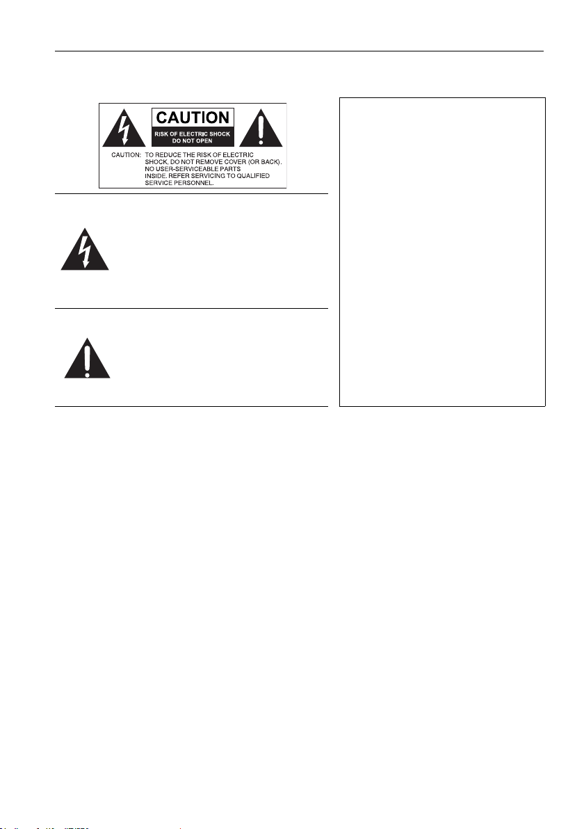
Safety warnings and precautions 1
Safety warnings and precautions
THIS EQUIPMENT MUST BE
GROUNDED
To ensure safe operation, the threepin plug must be inserted only into a
standard three-pin power outlet which
The lightning ash with arrowhead
symbol, within an equilateral triangle, is
intended to alert the user to the
presence of uninsulated "dangerous
voltage" within the product's enclosure
that may be of sufcient magnitude to
constitute a risk of electric shock to
persons.
The exclamation point within an
equilateral triangle is intended to alert
the user to the presence of important
operating and maintenance (servicing)
instructions in the literature
accompanying the appliance.
• The mains plug of the power supply cord shall remain readily operable. The AC
receptacle (mains socket outlet) shall be installed near the equipment and shall be easily
accessible. To completely disconnect this equipment from the AC mains, disconnect the
power cord plug from the AC receptacle.
• Do not place this display on an uneven, sloping or unstable surface (such as a trolley)
where it may fall and cause damage to itself or others.
• Do not place this display near water, like a spa or pool, or in a position which will allow
the splashing or spraying of water onto the display, like in front of an open window
where rain water may enter.
• Do not install this display in a conned space without proper ventilation and air
circulation, such as in a closed cabinet. Allow proper space around the display for
dissipating heat inside. Do not block any openings and vents on the display. Overheating
may result in hazards and electric shock.
• Installation of this display should only be performed by a qualied technician. Failure to
install this display properly may cause injuries and damages to the personnels and the
display itself. Check the installation regularly and maintain the display periodically to
ensure the best working condition.
• Use only the accessories approved or recommended by the manufacturer to mount this
display. Using wrong or unsuitable accessories may cause the display to fall and result in
serious personal injuries. Make sure that the surface and xing points are strong enough
to sustain the weight of the display.
• To reduce the risk of electric shock, do not remove covers. No user serviceable parts
inside. Refer servicing to qualied service personnel.
• To prevent personal injuries, mounting the display or installing desktop stands is
required before use.
is effectively grounded through normal
household wiring. Extension cords
used with the equipment must have
three cores and be correctly wired to
provide connection to the ground.
Wrongly wired extension cords are a
major cause of fatalities.
The fact that the equipment operates
satisfactorily does not imply that the
power outlet is grounded or that the
installation is completely safe. For your
safety, if you are in any doubt about the
effective grounding of the power
outlet, please consult a qualied
electrician.
Page 6

Important safety instructions2
Important safety instructions
1. Read these instructions.
2. Keep these instructions.
3. Heed all warnings.
4. Follow all instructions.
5. Do not use this apparatus near water.
6. Clean only with dry cloth.
7. Do not block any ventilation openings. Install in accordance with the manufacturer's
instructions.
8. Do not install near any heat sources such as radiators, heat registers, stoves, or other
apparatus (including ampliers) that produce heat.
9. Do not defeat the safety purpose of the polarized or grounding-type plug. A polarized
plug has two blades with one wider than the other. A grounding-type plug has two
blades and a third grounding prong. The wide blade or the third prong are provided
for your safety. If the provided plug does not t into your outlet, consult an electrician
for replacement of the obsolete outlet.
10. Protect the power cord from being walked on or pinched particularly at plugs,
convenience receptacles, and the point where they exit from the apparatus.
11. Only use attachments/accessories specied by the manufacturer.
12. Use only with the cart, stand, tripod, bracket, or table specied by the
manufacturer, or sold with the apparatus. When a cart is used, use caution
when moving the cart/apparatus combination to avoid injury from tip-over.
14. Unplug this apparatus during lightning storms or when unused for long periods of
time.
15. Refer all servicing to qualied service personnel. Servicing is required when the
apparatus has been damaged in any way, such as power-supply cord or plug is
damaged, liquid has been spilled or objects have fallen into the apparatus, the
apparatus has been exposed to rain or moisture, does not operate normally, or has
been dropped.
Notes on the LCD panel of this display
• The Liquid Crystal Display (LCD) panel of this display has a very thin protective layer of
glass which is liable to marking or scratching, and cracking if struck or pressured. The
liquid crystal substrate is also liable to damage under excessive force or extreme
temperatures. Please handle with care.
• The response time and brightness of the LCD panel may vary with the ambient
temperature.
• Avoid placing the display in direct sun or where direct sun or spot lighting will shine
onto the LCD panel, as the heat may damage the panel and the external casing of the
display, and the bright light will make viewing the display more difcult than necessary.
• The LCD panel consists of individual pixels to display images and is manufactured
according to the design specications. While 99.9% of these pixels work normally, 0.01%
of the pixels may remain constantly lit (in red, blue or green) or unlit. This is a technical
limitation of the LCD technology and is not a defect.
Page 7

Important safety instructions 3
• LCD screens, like plasma (PDP) and conventional CRT (Cathode Ray Tube) screens, are
also susceptible to 'screen burn-in' or 'image retention' which can be found on the
screen as visible xed lines and shades. To avoid such damage to the screen, avoid
displaying still images (like On-Screen Display menus, TV station logos, xed/inactive
text or icons) for more than two hours. Change the aspect ratio from time to time. Fill
the entire screen with the image and eliminate the black bars whenever possible. Avoid
displaying images in 4:3 aspect ratio over a long period of time, otherwise there may be
visible burn marks on the screen as two vertical lines.
Note: Under certain circumstances, condensation may occur on the inner side of the
cover glass, it's a natural phenomenon and will not affect the operation of the display.
This condensation will usually disappear after around 2 hours of normal operation.
Safety notice for remote control
• Do not put the remote control in the direct heat, humidity, and avoid re.
• Do not drop the remote control.
• Do not expose the remote control to water or moisture. Failure to do so could result in
malfunction.
• Conrm there is no object between the remote control and the remote sensor of the
product.
• When the remote control will not be used for an extended period, remove the
batteries.
Battery safety notice
The use of the wrong type of batteries may cause chemical leaks or explosion. Please note
the following:
• Always ensure that the batteries are inserted with the positive and negative terminals in
the correct direction as shown in the battery compartment.
• Different types of batteries have different characteristics. Do not mix different types.
• Do not mix old and new batteries. Mixing old and new batteries will shorten battery life
or cause chemical leaks from the old batteries.
• When batteries fail to function, replace them immediately.
• Chemicals which leak from batteries may cause skin irritation. If any chemical matter
seeps out of the batteries, wipe it up immediately using a dry cloth, and replace the
batteries as soon as possible.
• Due to varying storage conditions, the battery life for the batteries included with your
product may be shortened. Replace them within 3 months or as soon as you can after
initial use.
• There may be local restrictions on the disposal or recycling of batteries. Consult your
local regulations or waste disposal provider.
Page 8

Important safety instructions4
BenQ ecoFACTS
BenQ has been dedicated to the design and development of greener product as part of its
aspiration to realize the ideal of the "Bringing Enjoyment 'N Quality to Life" corporate
vision with the ultimate goal to achieve a low-carbon society. Besides meeting
international regulatory requirement and standards pertaining to environmental
management, BenQ has spared no efforts in pushing our initiatives further to incorporate
life cycle design in the aspects of material selection, manufacturing, packaging,
transportation, using and disposal of the products. BenQ ecoFACTS label lists key ecofriendly design highlights of each product, hoping to ensure that consumers make
informed green choices at purchase. Check out BenQ's CSR Website at http://csr.BenQ.
com/ for more details on BenQ's environmental commitments and achievements.
Page 9
Unpacking and Installation 5
Unpacking and Installation
Unpacking
• This product is packed in a carton, together with the standard accessories.
• Any other optional accessories will be packed separately.
• Due to the size and weight of this display it is recommended for two people to move it.
• After opening the carton, ensure that the contents are complete and in good condition.
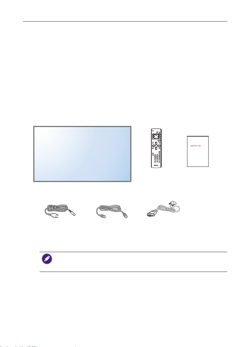
Package Contents
Please verify that you received the following items with your package content:
• LCD display
• Remote control
• Quick start guide
Power Cord HDMI cable DVI to VGA cable
* The supplied power cord varies depending on destination.
* Differences according to regions.
Display design and accessories may differ from those illustrated above.
• For all other regions, apply a power cord that conforms to the AC voltage of the power socket
and has been approved by and complies with the safety regulations of the particular country
(Type H05VV-F ,2G or 3G, 0.75 or 1mm2 should be used).
• You might like to save the package box and packing material for shipping the display.
• Power cord (1.8 m)
• HDMI cable (1.8 m)
• DVI to VGA cable (1.8 m)
Remote Control Quick start guide
Installation Notes
• Due to the high power consumption, always use the plug exclusively designed for this
product. If an extended line is required, please consult your service agent.
• The product should be installed on a at surface to avoid tipping. The distance between
the back of the product and the wall should be maintained for proper ventilation. Avoid
installing the product in the kitchen, bathroom or any other places with high humidity so
as not to shorten the service life of the electronic components.
Page 10
Unpacking and Installation6
• The product can normally operate only under 3000m in altitude. In installations at
altitudes above 3000m, some abnormalities may be experienced.
• LCD screens, like plasma (PDP) and conventional CRT (Cathode Ray Tube) screens, are
also susceptible to ‘screen burn-in’ or ‘image retention’ which can be found on the
screen as visible xed lines and shades. To avoid such damage to the screen, avoid
displaying still images (like On-Screen Display menus, TV station logos, xed/inactive
text or icons) for more than 30 minutes. Change the aspect ratio from time to time. Fill
the entire screen with the image and eliminate the black bars whenever possible. Avoid
displaying images in 4:3 aspect ratio over a long period of time, otherwise there may be
visible burn marks on the screen as two vertical lines.
Under certain circumstances, condensation may occur on the inner side of the cover glass, it’s a
natural phenomenon and will not affect the operation of the display. This condensation will usually
disappear after around 2 hours of normal operation.
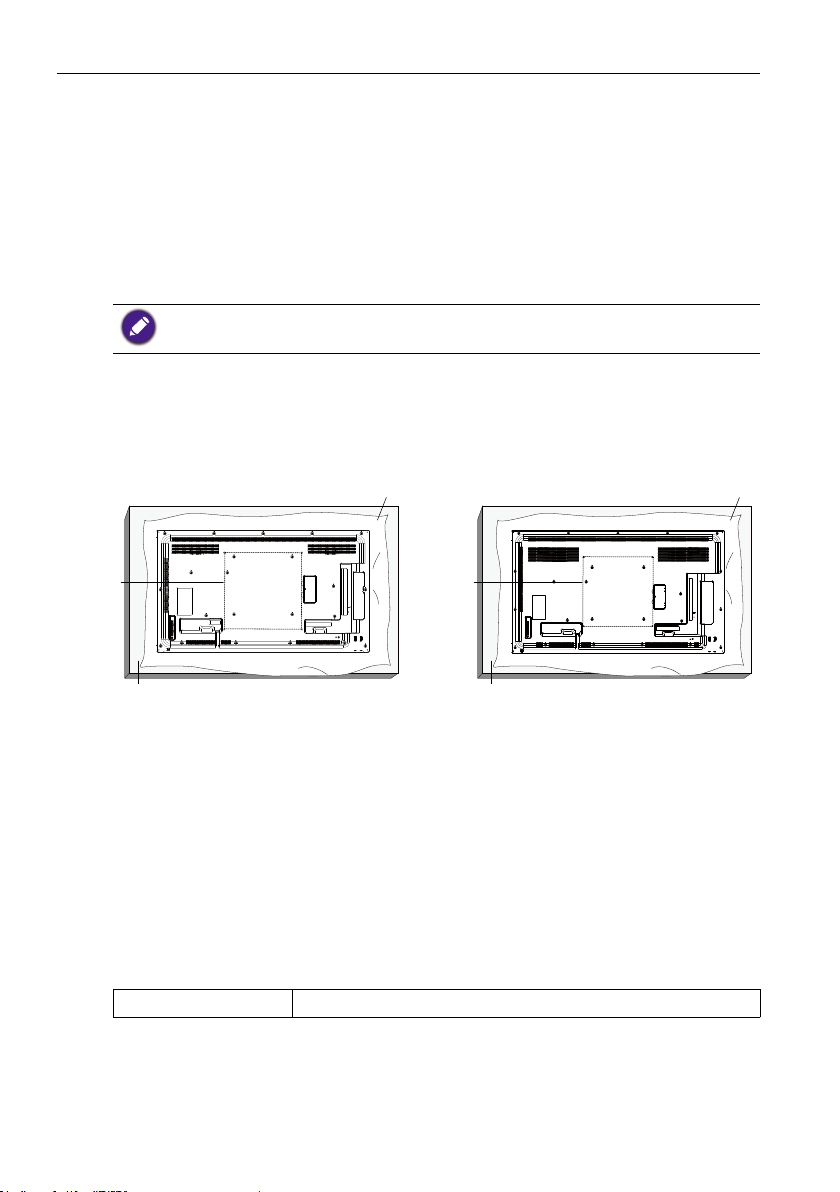
Mounting on a Wall
To mount this display to a wall, you will have to obtain a standard wall-mounting kit
(commercially available). We recommend using a mounting interface that complies with
TUV-GS and/or UL1678 standard.
SL490
Protective Sheet
SL550
Protective Sheet
VESA Grid
Table
VESA Grid
Table
1. Lay a protective sheet on a table, which was wrapped around the display when it was
packaged, beneath the screen surface so as not to scratch the screen face.
2. Ensure you have all accessories for mounting this display (wall mount, ceiling mount,
table stand, etc).
3. Follow the instructions that come with the base mounting kit. Failure to follow
correct mounting procedures could result in damage to the equipment or injury to
the user or installer. Product warranty does not cover damage caused by improper
installation.
4. For the wall-mounting kit, use M6 mounting screws (having a length 10 mm longer
than the thickness of the mounting bracket) and tighten them securely.
VESA Grid
SL490/SL550 400(H) x 400(V) mm
Page 11
Unpacking and Installation 7
SL490
To prevent the display from falling:
• For wall or ceiling installation, we recommend installing the display with metal brackets which
are commercially available. For detailed installation instructions, refer to the guide received with
the respective bracket.
• To lessen the probability of injury and damage resulting from fall of the display in case of
earthquake or other natural disaster, be sure to consult the bracket manufacturer for installation
location.
Ventilation Requirements for enclosure locating
To allow heat to disperse, leave space between
surrounding objects as shown in the diagram
below.
100 mm 100 mm
100 mm
100 mm
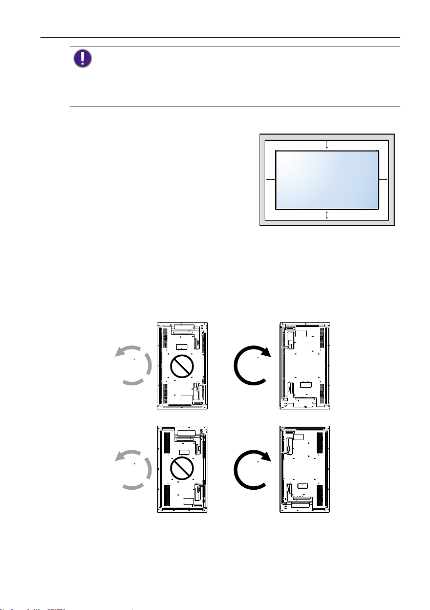
Mounting in Portrait Position
This display can be installed in portrait position.
1. Remove the table stand, if attached.
2. Rotate 90 degrees clockwise from the back side of the display .The terminals will be
on the left and bottom side of the user from the back of the display.
90
SL550
90
90
90
Page 12
Parts and Functions8
4
5
6
Parts and Functions
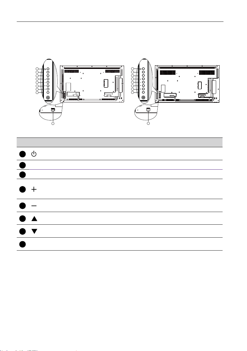
Control Panel
SL490 SL550
1
MUTE INPUT
2
3
4
5
6
7
MENU
8
9
1
MUTE INPUT
2
3
4
5
6
7
MENU
8
9
No. Name Description
1
button
MUTE button
2
INPUT button
3
Use this button to turn the display on or put the display to
standby.
Switch the audio mute ON/OFF.
Choose the input source.
Increase the adjustment while OSD menu is on, or increase the
button
audio output level while OSD menu is off.
• Used as OK button in the On-Screen-Display menu.
button
button
7
button
MENU button
8
Decrease the adjustment while OSD menu is on, or decrease
the audio output level while OSD menu is off.
Move the highlight bar up to adjust the selected item while OSD
menu is on.
Move the highlight bar down to adjust the selected item while
OSD menu is on.
Return to previous menu while OSD menu is on, or to activate
the OSD menu when OSD menu is off.
Page 13
9
Remote control
sensor and power
status indicator
Parts and Functions 9
• Receives command signals from the remote control.
• Indicates the operating status of the display:
- Lights green when the display is turned on
- Lights red when the display is in standby mode
- Lights amber when the display enters sleep mode
- When SCHEDULE is enabled, the light blinks green and red
- If the light blinks red, it indicates that a failure has been
detected
- Lights off when the main power of the display is turned off
• Pull down the lens to have better remote control performance
and easy to observe the light information of power status.
• Push up the lens before mounting the display for video wall
application.
• Pull/Push the lens until hearing the click sound.
Page 14
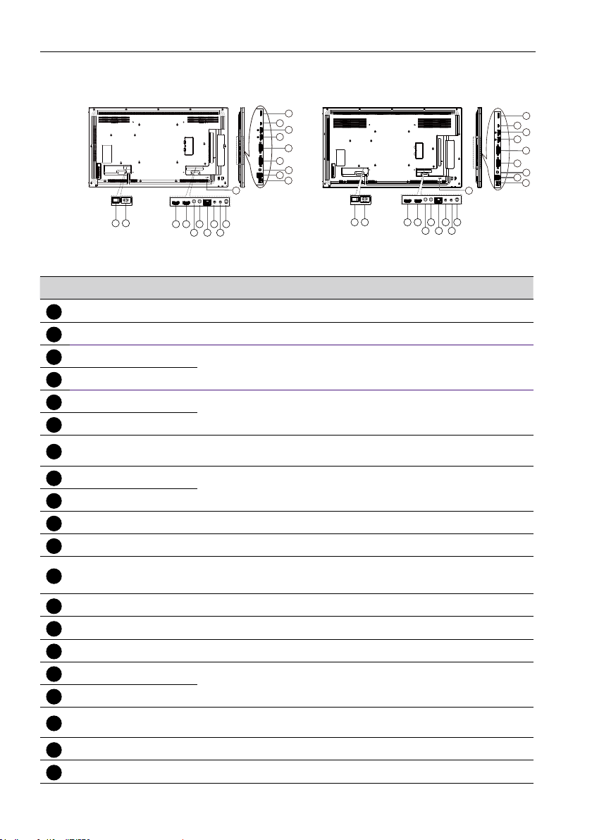
Parts and Functions10
1
2
3
4
5
6
7
8
9
10
11
14
15
16
17
18
20
Input/Output Terminals
SL490 SL550
19
18
17
16
15
14
13
12
20
11
19
18
17
16
15
14
13
12
20
11
21
43 658710
9
21 43 658710
No. Name Description
AC SWITCH
AC IN
HDMI1 IN
Switch the AC power on/off.
AC power input from the wall outlet.
HDMI video/audio input.
HDMI2 IN
IR IN
IR signal input / output for the loop-through function.
IR OUT
RJ-45
RS232 IN
LAN control function for the use of remote control signal from
control center.
RS232 network input / output for the loop-through function.
RS232 OUT
Audio OUT
USB PORT B
USB PORT A
12
PC LINE IN
13
DVI IN
DVI OUT
DisplayPort IN
Audio output to external AV device.
Service Use only.
1. For media play
2. 5V2A for add current , example for HDD
Audio input for VGA source (3.5mm stereo phone).
DVI-I video input.
DVI or VGA video output.
DisplayPort video input / output.
DisplayPort OUT
MICRO USB
MICRO SD CARD
19
SECURITY LOCK
For media play, transfer data between the signage and the
computer via a Micro-USB cable (purchased separately).
Connect your MICRO SD CARD.
Used for security and theft prevention.
9
Page 15
Parts and Functions 11
4
5
9
10
Remote control
General functions
1
2
3
4
5
6
7
8
9
10
11
POWER button
1
Power ON/OFF.
2
PLAY buttons
Media player source only. Please refer to
Remote Control for Android usage on page
14.
Freeze feature
Pause: Freeze hot key for all inputs
content.
Play: Unfreeze hot key for all input
content.
3
SOURCE button
Pop-up source menu OSD.
12
13
14
15
16
HOME button
Pop-up setting menu OSD.
LIST button
Works as X-Sign Menu when at X-Sign page.
6
NAVIGATION buttons
On VGA, HDMI1, HDMI2,DVI-D and Display
Port source: Pop-up picture mode source OSD.
Others: Move the highlight bar up.
On VGA, HDMI1, HDMI2,DVI-D and Display
Port source: Pop-up Audio source OSD.
Others: Move the highlight bar down.
Source menu OSD: Exit source menu OSD.
Volume menu OSD: Decrease audio volume.
Others: Move the highlight bar left..
Source menu OSD: Go to selected source.
Volume menu OSD: Increase audio volume.
Others: Move the highlight bar right.
7
OK button
Conrm, submit or select.
8
ADJUST button
Go to Auto Adjust OSD for VGA only.
MUTE button
Toggle Audio Mute/Unmute.
/ / / COLOR buttons
Choose tasks or options.(for Media Input only)
Window selection for PIP function.
11
Number / ID SET / ENTER buttons
Enter text for network setting.
Press to set the display ID. Refer to ID Remote
Control on page 13 for more detail.
Page 16
Parts and Functions12
12
13
FORMAT button
Change Image Zoom Mode Full, 4:3, 1:1,
16:9, 21:9, Custom.
BACK button
Return to the previous menu page or exit
from the previous function.
14
INFO button
Show Information OSD.
15
OPTIONS button
No function.
16
/ VOLUME button
Adjust volume.
Page 17
Parts and Functions 13
ID Remote Control
You can set the remote control ID when you want to use this remote control on one of
several different displays.
Press ID button. The red LED blinks twice.
1. Press ID SET button for more than 1 second to enter the
ID Mode. The red LED lights up.
Press the ID SET button again will exit the ID Mode. The
red LED lights off.
Press the digit numbers 0 ~ 9 to select the display you want to
control.
For example: press 0 and 1 for display No.1, press 1 and 1 for
display No.11.
The numbers available are from 01 ~ 98.
2. Not pressing any button within 10 seconds will exit the ID
Mode.
3. If an error pressing of buttons other than the digits
occurred, wait 1 second after the red LED lights off and
then lights up again, then press the correct digits again.
4. Press ENTER button to conrm. The red LED blinks
twice and then lights off.
• Press NORMAL button. The green LED blinks twice, indicating the
display is in normal operation.
• It is necessary to set up the ID number for each display before selecting
its ID number.
Page 18
Parts and Functions14
2
Remote Control for Android usage
1
2
3
4
5
6
7
8
9
10
11
POWER button
1
Power ON/OFF.
PLAY buttons
1. Media playback (video/audio/picture).
There are 3 ways to play media les.
1) Media Player > Compose > edit or
add new playlist > choose any media
les > press
to play the media
le directly.
2) Media Player > Play > choose nonempty play list > press
the media les in the play list.
3) Set media playlist in Boot on Source
or Schedule by OSD menu.
12
13
14
15
16
to play all
2. PDF playback
There are 3 ways to play PDF les.
1) File Manager
Select and play the PDF le from File
Manager.
2) PDF Player > Play > choose non-empty play
list > press
to play all the PDF les in
the play list.
3) Set PDF playlist in Boot on Source or
Schedule by OSD menu.
3. When playing PDF, video or music, press
to stop playing. Then if pressing again,
playing will be started from the beginning of
the le.
4. When playing PDF, video or music, press
button to pause playing.
5. All media or PDF les should be put at the
folder, which is named “benq” with subfolder, under the root directory of the
specied storage (internal/USB/SD Card). All
sub-folders (video/photo/music/pdf) are
named by media types and shouldn’t be
changed.
- videos: {root dir of storage}/benq/video/
- photos: {root dir of storage}/benq/photo/
- music: {root dir of storage}/benq/music/
- pdf: {root dir of storage}/benq/pdf/
Note that the root directories of three storages
are
- Internal storage: /sdcard
- USB storage: /mnt/usb_storage
- SD card: /mnt/external_sd
6.
Media Player: Rewind 20 seconds.
PDF Player: Go to the previous page.
7.
Media Player: Forward 20 seconds.
PDF Player: Go to the next page
3
SOURCE button
Root Menu: Go to Video source OSD.
Page 19
Parts and Functions 15
4
5
9
10
11
12
HOME button
Root Menu: Go to Main Menu OSD.
Others: Exit OSD.
LIST button
In PDF Player, zoom-in your PDF content.
When you Press
button, the PDF content will
go back to the original size.
6
/ / / NAVIGATION buttons
1. Navigate through menus and choose items.
2. In the content of the web page, these buttons
are to control the scroll bar of the screen.
Press
or is for moving vertical scroll
bar up or down. Press or is for
moving horizontal scroll bar left or right.
3. For PDF les,
- when zoom in/out has been performed,
Press
, , or to adjust the
position of the screen.
- when zoom in/out has been not performed,
Press
to go to the next page.
Press to go to the previous page.
7
OK button
2) Move the focus up to the next
control or widget such as buttons.
3.
1) In the content of the web page, move
the focus down to the next clickable
items.
2) Move the focus down to the next
control or widget such as buttons.
Number / ID SET / ENTER button
1. No functions for ID SET and
ENTER
on Android source.
2. For PDF le, enter the page number by
pressing number buttons and then
press
button to jump to the specic
page.
FORMAT button
Change Image Zoom Mode Full, 4:3, 1:1,
16:9, 21:9, Custom.
13
BACK button
Return to the previous page or exit from
the previous function.
14
INFO button
Conrm, submit or select.
8
ADJUST button
In PDF Player, zoom-out your PDF content.
When you Press
button, the PDF le content
will go back to the original size.
MUTE button
1. Show Information OSD.
2. Media Player > Compose > edit or new
add playlist > choose any media les >
press
to show the information of
the chosen media le.
15
OPTIONS button
Open toolbox in Media Player or PDF
Toggle Audio Mute/Unmute.
/ / / COLOR buttons
1. : No function in Android.
2.
Player.
1. Media Player >Compose > Edit or new
add playlist > press
to open
toolbox. Toolbox will be slide from the
left side of the screen.
1) In the content of the web page, move the
focus up to the next clickable items.
Page 20
Parts and Functions16
2. PDF Player >Compose > Edit or new add
playlist > press
to open toolbox.
Toolbox will be slide from the left side of the
screen.
16
/ VOLUME button
Adjust volume.
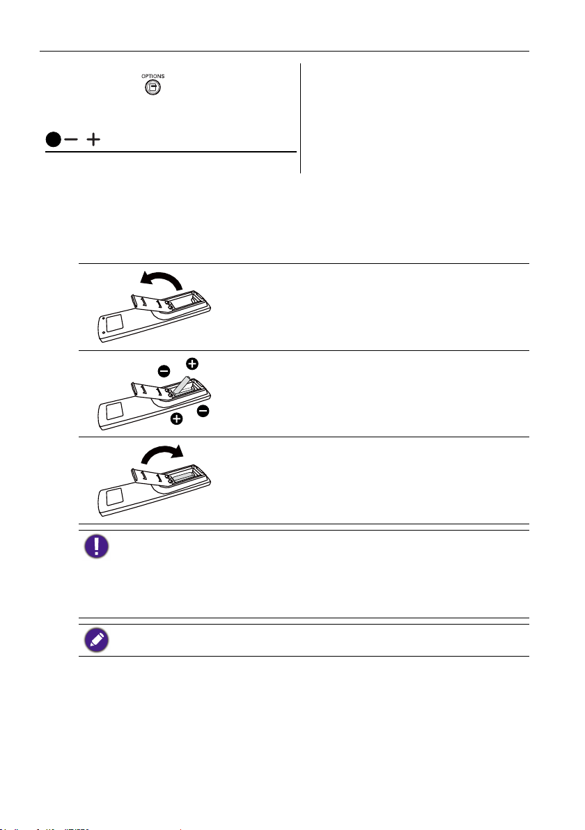
Inserting the batteries in the remote control
The remote control is powered by two 1.5V AAA batteries.
To install or replace batteries:
1. Buy two 1.5V AAA batteries.
2. Press and then slide the cover to open it.
3. Align the batteries according to the (+) and (–)
indications inside the battery compartment.
4. Replace the cover.
The incorrect use of batteries can result in leaks or bursting. Be sure to follow these instructions:
• Place “AAA” batteries matching the (+) and (–) signs on each battery to the (+) and (–) signs of
the battery compartment.
• Do not mix battery types.
• Do not combine new batteries with used ones. It causes shorter life or leakage of batteries.
• Remove the dead batteries immediately to prevent them from liquid leaking in the battery
compartment. Don’t touch exposed battery acid, as it can damage your skin.
If you do not intend to use the remote control for a long period, remove the batteries.
Handling the remote control
• Do not subject to strong shock.
• Do not allow water or other liquid to splash the remote control. If the remote control
gets wet, wipe it dry immediately.
• Avoid exposure to heat and steam.
• Other than to install the batteries, do not open the remote control.
Page 21
Parts and Functions 17
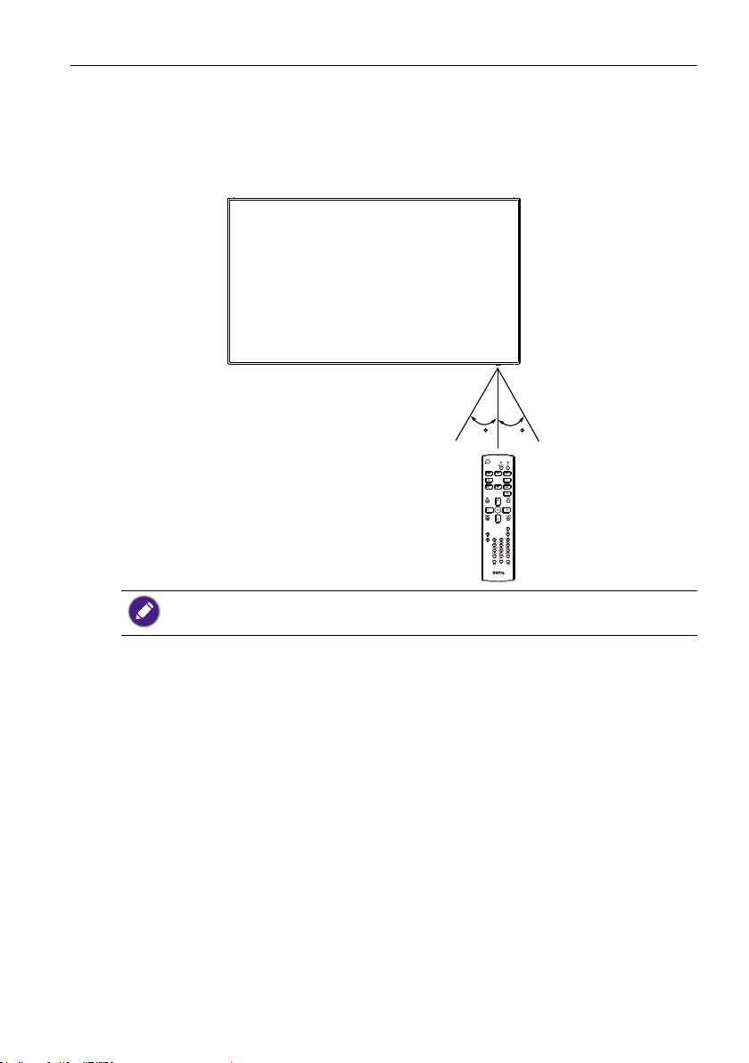
Operating range of the remote control
Point the top of the remote control toward the display’s remote control sensor when
pressing a button.
Use the remote control within a distance of less than 5m/16ft from the display’s sensor,
and a horizontal and vertical angle of less than 30 degrees.
30 30
The remote control may not function properly when the remote control sensor on the display is
under direct sunlight or strong illumination, or when there is an obstacle in the path of signal
transmission.
Page 22
Connecting External Equipment18
Connecting External Equipment
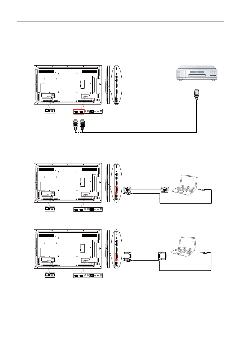
Connecting External Equipment (DVD/VCR/VCD)
Using HDMI video input
HDMI IN
Connecting a PC
Using DVI-I input
VGA Out
DVI-I IN
VGA AUDIO IN
D-Sub 15 pin
DVD / VCR / VCD
HDMI Out
Audio Out
PC
Using DVI input
DVI IN
VGA AUDIO IN
DVI Out
Audio Out
PC
Page 23
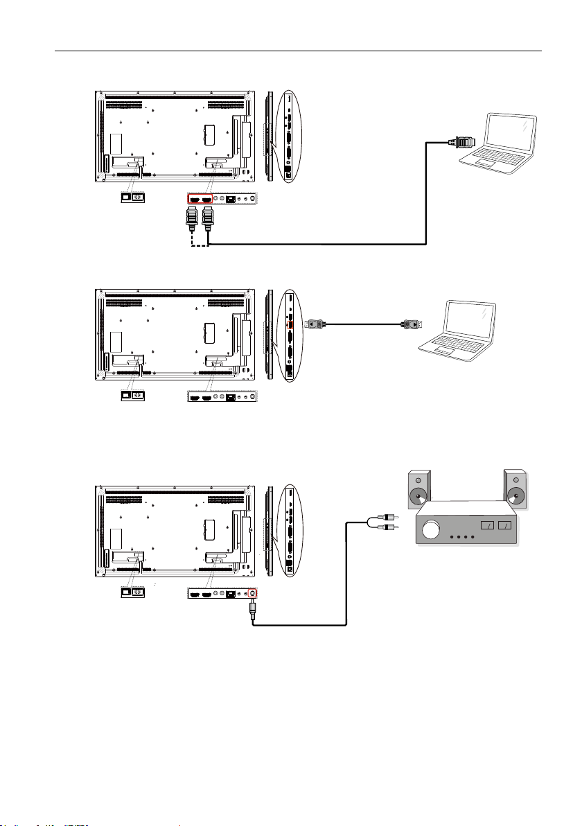
Using HDMI input
HDMI IN
Using DisplayPort input
Connecting Audio Equipment
Connecting External Equipment 19
HDMI Out
PC
DisplayPort Out
PC
Connecting an external audio device
AUDIO OUT
Audio In
Stereo Amplier
Page 24
Connecting External Equipment20
Connecting Multiple Displays in a Daisy-chain
Conguration
You can interconnect multiple displays to create a daisy-chain conguration for
applications such as a video wall.
Maximum 25 displays (5x5) can be used in a DVI daisy-chain conguration. For VGA daisy-chain,
Maximum 9 displays can be used.
Display control connection
Connect the RS232 OUT connector of DISPLAY 1 to the RS232 IN connector of
DISPLAY 2.
DISPLAY 1 DISPLAY 2
PC
RS-232C
Digital video connection
Connect the DVI OUT / DVI-I OUT connector of DISPLAY 1 to the DVI IN connector of
DISPLAY 2.
RS-232C INRS-232C OUTRS-232C IN
DISPLAY 1 DISPLAY 2
PC
DVI
DVI Daisy chain to 5*5 without splitter, DVI with HDCP up to 7th.
DVI IN DVI/DVI-I OUT DVI IN
Connect the DP OUT connector of DISPLAY 1 to the DP IN connector of DISPLAY 2.
DISPLAY 1 DISPLAY 2
PC
DP
DP IN DP OUT DP IN
Page 25
Connecting External Equipment 21
DP Daisy chain to 15*10 without splitter. DP 1.2 up to 3840x2160@60Hz. DP with HDCP up to
7th.
Connect the HDMI OUT connector of DISPLAY 1 to the DVI IN connector of DISPLAY
2.
DVD / VCR / VCD
HDMI
DISPLAY 1 DISPLAY 2
DVI IN DVI OUT DVI IN
HDMI up to 3840x2160@30Hz, HDMI with HDCP up to 7th.
Analog video connection
Connect the DVI OUT /DVI-I OUT connector of DISPLAY 1 to the DVI-I IN connector
of DISPLAY 2.
DISPLAY 1 DISPLAY 2
PC
DVI-I
Analog Daisy chain to 3*3 without splitter.
DVI-I IN DVI/DVI-I OUT DVI-I IN
IR connection
External
IR Receiver
1. This display’s remote control sensor will stop working if the IR IN is connected.
2. IR loop through connection can support up to 9 displays.
DISPLAY 1 DISPLAY 2
IR IN IR OUT IR IN
Page 26

Operation22
Operation
The control button described in this section is mainly on the remote control unless specied
otherwise.
Watch the Connected Video Source
See page 18 for external equipments connection.
1. Press
2. Press
Change Picture Format
You can change the picture format to suit the video source. Each video source has its
available picture formats.
The available picture formats depend on the video source:
1. Press
2. Press
Android reminder page
1. Android reminder page:
SOURCE button.
or button to choose a device, then press OK button.
FORMAT button.
or button to choose a picture format, then press OK button.
• PC mode: Full/4:3/1:1/16:9/21:9/Custom.
• Video mode: Full/4:3/1:1/16:9/21:9/Custom.
• Every app leaves by pressing the back key. The screen will go to Android reminder
page.
• When you return to Android reminder page, the screen will show hint image as
below:
• The hint image will notify you can press source key to change source.
Page 27
Operation 23
Media Player introduction:
1. Home page of Media Player, this page has three items: “Play”, “Compose” and
“Settings”.
Play : select playlist to play.
Compose: edit playlist.
Settings: setting play properties.
2. Select “Play” on home page, rst you should choose one playlist to play between FILE
1 and FILE 7.
The pencil icon means the playlist is non-empty.
3. Select “Compose” on home page, rst you should choose one playlist to edit between
FILE 1 and FILE 7.
The pencil icon means the playlist is non-empty.
Page 28
Operation24
4. If an empty playlist is chosen, the app will guide you to select the media source.
All media les should be placed in/benq/of root directory.
For example:
• videos in /root/benq/video/
• photos in /root/benq/photo/
The limit of resolution is 4096x4096
• music in /root/benq/music/
5. You could edit or delete a non-empty playlist, just choose the desired playlist which is
with pencil icon.
Page 29
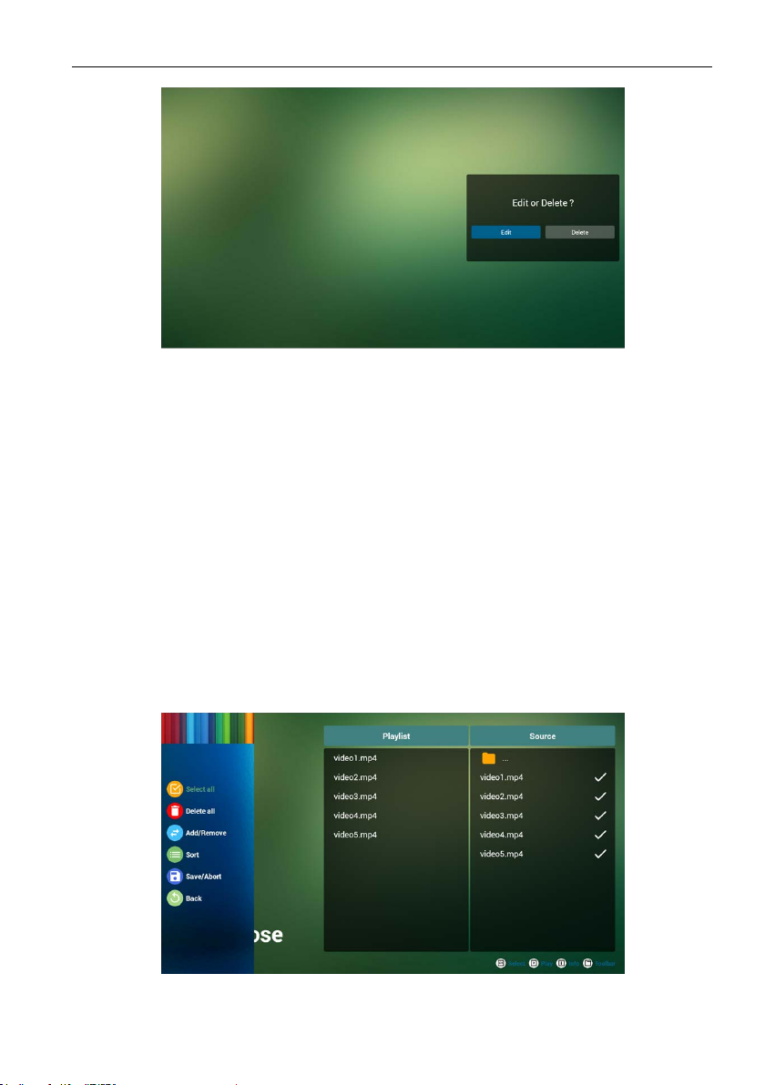
6. Once you start to edit a playlist, you will see below screen.
Source - les in storage.
Playlist – les in playlist.
There are 4 icons which map to the keys of remote controller.
Option key – launch slide bar
Play key – play media le.
Info key – show media info.
Ok key – select/unselect le.
6-1 In the slide bar, it helps you to do the following:
• select all : select all storage les.
• delete all : delete all playlist les.
• add/remove : update playlist from source.
• sort : sort playlist.
• save/abort : save or abort playlist.
• back : return.
Operation 25
7. if you choose “Sort” in the slide bar, you can change the order of les one by one.
Page 30

Operation26
8. Press info key after you choose desired le, you will get the detail information.
9. Press play key after you choose desired le, you will play the media le directly.
10. If you make a playlist with all image les, before saving, the app will ask you if you want
to have background music while playing slideshow.
Page 31

Operation 27
11. Select “Settings” on home page, this page has three parts, “Repeat Mode”, “Slideshow
Effect” and “Effect Duration”.
Repeat Mode : play mode.
Slideshow Effect : photo slideshow effect.
Effect Duration : photo effect duration.
12. Media Hotkey
Play : Playback le.
Pause: Pause le.
Fast forward: forward 20 second. (photo not support).
Rewind: back 20 second. (photo not support).
Stop: Stop le and return to start. For GIF format, it will be paused.
Browser manual
1. Home page of Browser app, this page has one item: “Settings”.
Press Settings then enter next page.
Page 32

Operation28
2. Users can choose 1~7.
Press any one will show a dialog.
3. Enter URL and press OK then data will save on List
Page 33

4. Press “Option” then left side will pop up a list
Import : Import URL list le
Export : Export URL list le
Delete all : Delete all URL record on right side
Back : left side list will be closed.
Operation 29
4.1 Import
• Click import
Page 34

Operation30
• Choose storage
• Choose le contains URL
• Import le and URL will show on list
Page 35

• File format for import
Format should be like below with le extension “txt”
Operation 31
4.2 Export:
• Click export
Page 36

Operation32
• Choose storage
• The dialog shows le path and name.
Press “save” button then URL on list will be saved.
5. Press OK then URL records will be saved.
Page 37

Operation 33
6. On URL list page, if you select non-empty item, it will show a dialog to ask edit or play
URL. If press “Edit”, it will show edit URL dialog, if press “Play”, it will show web page
of item’s URL.
7. OSD menu interaction with Browser
7.1 Demonstration: Boot on source
Page 38

Operation34
• Set OSD menu > Conuration1 > Boot on source > If Input is BROWSER and Play List
is 0.
Then PD will show Browser after reboot.
• Set OSD menu > Conuration1 > Boot on source > If Input is BROWSER and Play List
is 1.
Then PD will show web page with 1st URL in Browser app.
7.2 Demonstration: Scheduling
Set OSD menu > Advanced option > Schedule > On time1, Off time2, Input is
BROWSER, any day you want of week, and Play List.
Then PD will show web page with URL in Browser app at time1 and nish at time2.
PDF reader play
1. Home page of PDF Player, this page has three items: “Play”, “Compose” and
“Settings”.
Play : select playlist to play.
Compose: edit playlist.
Settings: setting play properties.
2. Select “Play” on home page, rst you should choose one playlist to play between FILE
1 and FILE 7.
The pencil icon means the playlist is non-empty.
Page 39

Operation 35
3. Select “Compose” on home page, rst you should choose one playlist to edit between
FILE 1 and FILE 7.
The pencil icon means the playlist is non-empty.
4. If an empty playlist is chosen, the app will guide you to select the media source.
All media les should be placed in /benq/ of root directory.
For example,
• pdfs in /root/benq/pdf/
Page 40

Operation36
5. You could edit or delete a non-empty playlist, just choose the desired playlist with
pencil icon.
6. Once you start to edit a playlist, you will see below screen.
Source - les in storage.
Playlist – les in playlist.
There are 4 icons which map to the keys of remote controller.
Option key – launch slide bar
Play key – play media le.
Info key – show media info.
Ok key – select/unselect le.
6-1 In the slide bar, it helps you to do the following:
• select all : select all storage les.
• delete all : delete all playlist les.
• add/remove : update playlist from source.
• sort : sort playlist.
• save/abort : save or abort playlist.
• back : return.
Page 41

Operation 37
7. If you choose “Sort” in the slide bar, you can change the order of les one by one.
8. Select “Settings” on home page, this page has two parts, “Repeat Mode” and “Effect
Duration”.
Repeat Mode : play mode.
Effect Duration : photo effect duration.
Media Hotkey:
Page 42

Operation38
Play : Playback le.
Pause: Pause page.
Fast forward: go to next page, if the page is end of the le, it will go to next le.
Rewind: back to last page, if the page is rst of the le, it will back to last le.
Stop: return to rst page of le
Color Hotkey:
LIST : Zoom in.(+10%)
ADJUST : Zoom out.(-10%)
OK : Restore zoom
Arrow keys:
Up/Down/Left/Right : Adjust page. (When the page has zoomed in/out)
Left : Previous Page. (When the page has not zoomed in/out)
Right : Next Page. (When the page has not zoomed in/out)
Combination key:
Number key + OK key : select specic page, and press ok key to change page.
• Press number key.
• Press OK key, the bottom of the page will show the page number, if page number
over total page number, it will not change page and show current page number at
the bottom of the page.
Page 43

signage display
Setting
Setting main items:
1. Wi-Fi
2. Ethernet
3. Signage Display
4. System Tools
5. Storage
6. Apps
7. Security
8. Date & time
9. Developer options
10. About
signage display 39
Wi-Fi
Via Enable/Disable to control Wi-Fi On/OFF. After Enable, the screen will
list all available WiFi AP.
1. Please make sure your Wi-Fi dongle is approved by BenQ
2. Ethernet will be disable automatically if Wi turn on and connect to network.
Page 44

signage display40
Ethernet
Via Enable/Disable to control Ethernet On/Off.After enable Ethernet, it will display:
1. Connect Type (available type is DHCP/Static IP)
A. DHCP
B. Static IP
C. IP Address
D. Netmask
E. DNS Address
F. Gateway Address
2. Mac Address
WiFi will be disable automatically if Ethernet turn on and connect to network.
DHCP
DHCP mode:
1. Cannot modify IP Address, Netmask, DNS Address and Gateway..
Page 45

signage display 41
2. If connect successfully, it will display current network conguration.
Static IP
Under Static IP. User can manually input IP Address, Netmask, DNS Address and
Gateway.
IP address, netmask, DNS address and gateway address input limitation.
1. Format:
I. number 0-9
II. decimal point “.”
Signage Display
Divide into 2 groups: General Settings / Source Settings
1. General Settings
A. Signage Display Name
B. Boot Logo
2. Source Settings
A. Media Player
Page 46

signage display42
B. Browser
C. PDF Player
General Settings
1. Signage Display Name
Set up PD name “PD_” + Ethernet Mac Address.
Input limitation:
1. length: Max 36 characters
2. format: no limit
2. Boot Logo
1) Scalar OSD menu to control Android boot logo enable/disable.
Scalar OSD Menu operation:
RCU: Home > Conguration2 > Logo > On/Off/User
In User mode, user can choose their own boot logo animation le.
1. Boot animation le name must be: bootanimation.zip
2. Will pop-up a window for user to select USB and SD card. No priority issue.
Page 47

signage display 43
2) When boot logo selection, PD will check if there is bootanimation.zip under USB and
SD card.
Function introduction:
a. Option description
/data/local
Use customized boot animation le which is copied from SD card or USB
/mnt/external_sd
Use boot animation le under SD card
/mnt/usb_storage
Use boot animation le under USB
b. Save
Press Save key to save SD card or USB bootanimation.zip to /data/local and set it as
boot logo.
c. Forget
Press Forget key to delete /data/local bootanimation.zip and not show boot logo.
d. Cancel
Close dialogue w/o changes.
Scenario introduction:
Page 48

signage display44
Case 1
The users do not settle customized boot logo. PD does not nd any bootanimation.
zip le under SD and USB. The List will be blank. Save and Forget button will be gray
and useless.
Case 2
The users do not settle customized boot log, PD nd bootanimation. zip le under SD
or USB. The screen will show bootanimation.zip and select the rst le automatically.
Case 3
The user settle customized boot logo, The screen will show /data/local/
bootanimation.zip
Page 49

signage display 45
3) If OSD menu Logo item is On or Off, the users cannot choose boot animation in
Android settings.
Source Settings
1. Media Player
Can Edit Media Player play list and effect settings.
Page 50

signage display46
1) Open Media Player Player List edit page.
2) Open Media Player slideshow effect edit page.
2. Browser
Can edit Bookmark conguration.
1) Open Browser setting page.
Page 51

3. PDF Player
Can edit PDF Player Play List and Effect Settings.
signage display 47
1) Open PDF Player Player List edit page.
2) Open PDF Player effect edit page.
Page 52

signage display48
System Tools
System tools 3 main functions:
1. Clear Storage
2. Factory Reset
3. Import & Export
Clear Storage
The purpose is to clear all data in Benq folders.
Divided into 4 mode:
1. Clear all benq folder.
2. Only clear benq folder under Internal storage.
3. Only clear benq folder under USB storage.
4. Only clear benq folder under SD card.
Pop-up the window to display all folders which can be clear.
Page 53

Factory Reset
Factory Reset can recover to Factory default settings.
signage display 49
Press OK to execute Reset function automatically.
Import & Export
Page 54

signage display50
The function of Import & Export PD settings.
1. Saved le name: settings.db
2. Will save to benq folder in storage.
1. Export
Will export settings.db to benq folder under USB or SD card.
If no benq folder exists in USB or SD card, it will be created automatically.
2. Import
Import settings.db from benq folder under USB or SD card.
Storage
Display current PD Android storage information.
Page 55

signage display 51
SD CARD and USB STORAGE :
Need to insert SD card or USB, the information will show up total space
and available of SD card or USB storage.
Apps
Display applications information.
Page 56

signage display52
Date & time
Adjust date, time and timezone via NTP.
Set date and time by yourself when you disable Automatic date & time setting.
Setting date
Page 57

Setting time
signage display 53
Developer options
Android developer options.
Page 58

signage display54
About
Main info in About:
1. BenQ Software Update
2. Android version
3. Kernel version
4. Build number
BenQ Software Update
Software upgrade via the Internet or USB device.
After select update.zip le, PD will restart and start to update.
Supplementary
Rotation
Via Scalar OSD menu to operate Rotation:
Home > Conguration2 > Rotation > OSD rotation
Page 59

1. Landscape
After set up Landscape mode, the setting screen will divide into 2 part.
Select Left item, right side will display the sub menu.
2. Portrait
After set up Portrait mode, the setting screen only display one layer.
signage display 55
Page 60

OSD Menu56
OSD Menu
An overall view of the On-Screen Display (OSD) structure is shown
below. You can use it as a reference for further adjusting your display.
Navigating the OSD Menu
Navigating the OSD menu using the remote control
SOURCE
1. Press button on the remote control to display the OSD menu.
2. Press
3. Press OK or
4. In the submenu, press
or button to choose the item you want to adjust.
button to enter the submenu.
or button to toggle among items, press or button to
adjust settings. If there is a submenu, press OK or
5. Press
button to return to the previous menu, or press button to exit the
OSD menu.
• When there is no OSD menu on the screen, press to display the menu of picture mode.
• When there is no OSD menu on the screen, press
FORMAT
INFOLIST
OPTIONSADJUST
to display the menu of Audio source.
button to enter the submenu.
Navigating the OSD menu using the display’s control buttons
1. Press MENU button to display the OSD menu.
2. Press
3. Press
4. In the submenu, press
5. Press MENU button to return to the previous menu, or press MENU button several
or button to choose the item you want to adjust.
button to enter the submenu.
or button to toggle among items, press or button
to adjust settings. If there is a submenu, press
times to exit the OSD menu.
button to enter the submenu.
Page 61

1
2
3
4
5
6
7
8
MUTE INPUT
MENU
9
OSD Menu Overview
P
Picture menu
OSD Menu 57
Picture
Screen
Audio
PIP
Conguration 1
Name Description
Brightness
(Picture)
Contrast
Brightness
Contrast
Sharpness
Black level
Tint
Color
Noise reduction
Gamma selection
Color temperature
Color control
Medium
Native
Native
Adjust the overall image and background screen
brightness(backlight).
Adjust the image contrast ratio for the input signal.
70
50
50
50
This function is digitally capable to keep crisp image at any
Sharpness
timings.
It is adjustable to get a distinct image or a soft one as you prefer
and set independently for each picture mode.
Page 62

OSD Menu58
Black level
Tint (Hue)
Color
(Saturation)
Noise Reduction
Gamma selection
Color
temperature
Color control
Picture mode
Overscan
Picture reset
Adjust the image brightness for the background.
sRGB picture mode is standard and cannot be changed.
Adjust the tint of the screen.
YUV signal only.
Adjust the color of the screen.
YUV signal only.
Adjust the noise reduction level.
YUV signal only.
Select a display gamma, It’s refer to the brightness performance
curve of signal input.Choose from Native / 2.2 / 2.4.
sRGB picture mode is standard and cannot be changed.
It is used to adjust the color temperature.
The image becomes reddish as the color temperature decreases,
and becomes bluish as the color.
The color levels of red, green, and blue are adjusted by the color
bars.
R: Red gain, G: Green gain, B: Blue gain.
Available when Color Temp. = User1 or User2 only.
PQ setting
PC mode: Standard / Highbright / sRGB.
Video mode: Standard / Highbright / Cinema.
Change the display area of the image.
ON: Set to display area about 95%.
OFF: Set to display area about 100%.
Reset all settings in the Picture menu.
Select “Yes” and press “SET” button to restore to factory preset
data.
Press “EXIT” button to cancel and then return to the previous
menu.
Page 63

Screen menu
OSD Menu 59
Picture
Screen
Audio
PIP
P
Conguration 1
H position
V position
Clock
Clock phase
Zoom mode
Custom zoom
Auto adjust
Screen reste
Name Description
H position
V position
Clock
Control Horizontal Image position within the display area of the
LCD.
Control Vertical Image position within the display area of the
LCD.
VGA input only.
Improves focus, clarity and image stability by increasing or
Clock phase
decreasing this setting.
VGA input only.
50
50
50
50
Full
Zoom
Action
Action
Page 64

OSD Menu60
Zoom mode
PC mode: Full / 4:3 / 1:1 / 16:9 / 21:9 / Custom.
Video mode: Full / 4:3 / 1:1 / 16:9 / 21:9 / Custom.
* Zoom mode setting is by input. If input in multi-windows, the
setting will apply for windows with the same input.
And the INFO OSD will show the latest setting.
Full
This mode restores the correct
proportions of pictures transmitted in
16:9 using the full screen display.
4:3
The picture is reproduced in 4:3 format
and a black band is displayed on either
side of the picture..
1:1
This mode displays the image pixel-bypixel on screen without scaling the
original image size.
16:9
The picture is reproduced in 16:9 format
and a black band at the top and bottom.
21:9
The picture is reproduced in 21:9 format
and a black band at the top and bottom.
Custom
Choose to apply the custom zoom
settings in the Custom Zoom submenu.
Page 65

Custom zoom
OSD Menu 61
You can use this function to further customize the zoom settings
to suit the image you want to display.
This item is functional only when the Zoom mode is set to Custom.
Zoom
Expands the horizontal and vertical sizes
of the image simultaneously.
H zoom
Expands the horizontal size of the image
only.
V zoom
Expands the vertical size of the image
only.
H position
Moves the horizontal position of the
image left or right.
V position
Moves the vertical position of the image
up or down.
Auto adjust
Screen reset
Press “Set” to detect and adjust H position, V position, Clock,
Phase automatically.
Reset all settings in the Screen menu to factory preset values.
Select “Yes” and press “SET” button to restore the factory
preset data.
Press “EXIT” button to cancel and then return to the previous
menu.
Page 66

OSD Menu62
Audio menu
Picture
Screen
Audio
PIP
P
Conguration 1
Picture
Screen
Audio
PIP
P
Conguration 1
Balance
Treble
Bass
Volume
Audio out (line out)
Maximum volume
Minimum volume
Mute
Audio source
Sync. Volume
Audio reset Action
Off
Digital
Off
50
50
50
30
30
100
0
Name Description
Balance
Treble
Bass
Volume
Audio out (line
out)
Maximum
volume
Minimum volume
Mute
Adjust to emphasize left or right audio output balance.
Adjust to increase or decrease higher-pitched sounds.
Adjust to increase or decrease lower-pitched sounds.
Adjust to increase or decrease the audio output level.
Adjust to increase or decrease line out output level.
Adjust your own limitation for the maximum volume setting. This
stops the volume from being played too loudly.
Adjust your own limitation for the minimum volume setting.
Turn the mute function on/off.
Page 67

Audio source
Sync. Volume
Audio reset
PIP menu
OSD Menu 63
Select the audio input source.
Analog: audio from audio input
Digital : audio from HDMI/DVI audio.
Displyport: audio from DP.
Enable/disable audio out (line out) volume adjustability to sync
with internal speakers.
Reset all settings in the Audio menu to factory preset values.
Picture
Screen
Audio
PIP
P
Conguration 1
Sub mode
PIP size
PIP position
PIP change
PIP Source
PIP Audio
PIP reset
Name Description
Select the sub mode.
Choose from: Off / PIP / POP / Quick swap / PBP.
Off PIP PBP 2Win
Sub mode
Quick swap
Off
Small
Bottom-Right
Action
VGA
Main
Action
Sub Win1
Input
Switch main on top
or sub on top.
PIP size
Select the size of the sub picture in the PIP (Picture-in-Picture) mode.
Choose from: Small / Medium / Large.
Page 68

OSD Menu64
PIP position
PIP change
PIP source
PIP audio
PIP reset
Select the position of the sub picture in the PIP (Picture-in-Picture)
mode.
Choose from: Bottom-Right / Bottom -Left / Top-Right / Top-
Left.
Exchange Main and PIP / PBP / Quick swap input signal.
Select the input signal for the sub picture.
Select the audio source in the Sub mode.
• Main - Select audio from the main picture
• Sub - Select audio from the sub picture.
Reset all settings in the PIP menu to factory preset values.
• The PIP function is available only for certain signal source combinations
as shown in the table below.
HDMI1 HDMI2 DVI DisplayPort VGA
HDMI1 O X X O O X X X X X
HDMI2 X O X O O X X X X X
DVI X X O O O* X X X X X
DisplayPort O O O O O O O O O O
VGA O O O* O O O O O O O
Medoa
Player
Browser X X X O O X O X X X
X-Sign X X X O O X X O X X
PDF
Reader
Android X X X O O X X X X O
X X X O O O X X X X
X X X O O X X X O X
Medoa
Player
Browser X-Sign
PDF
Reader
Android
(O: PIP function available, X: PIP function unavailable)
• The availability of the PIP function will also depend on the resolution of
the input signal being used.
Page 69

Conguration1 menu
OSD Menu 65
Picture
Screen
Audio
PIP
P
Conguration 1
Switch on state
Panel saving
RS232 routing
Boot on source
WOL
Power LED light
Conguration1 reset
Factory reset
Name Description
Select the display status used for the next time you connect the
power cord.
• Power off - The display will remain off when the power cord is
connected to a wall outlet.
Switch on state
• Forced on - The display will turn on when the power cord is
connected to a wall outlet.
• Last status - The display will return to the previous power
status (on/off/standby) when removing and replacing the power
cord.
Choose to enable the panel saving functions and thus reduce the
risk of “image persistence” or “ghost-imaging”.
• Brightness - Select On and the image brightness will be
Panel saving
reduced to an appropriate level. The Brightness setting in the
Picture menu will be unavailable when selected.
• Pixel shift - Select the time interval (Auto / 10 ~ 900 Seconds
/ Off) for the display to slightly expand the image size and shift
the position of pixels in four directions (up, down, left, or right).
RS232 routing
Select the network control port.
Choose from: RS232 / LAN > RS232.
Choose to select source when boot up.
Input: select input source when bootup.
Boot on source
Playlist: select playlist index for Media player, Browser, PDF
player.
0: no play list. Same as switch source from OSD.1~7: playlist
number.
WOL
Choose to turn on or off the wake on LAN function.
Choose from : Off / On
Last status
Action
RS232
Action
Off
On
Action
Action
Page 70

OSD Menu66
Power LED light
Conguration1
reset
Choose to set power indicate LED on or off.
Choose On for normal use.
Reset all settings in Conguration1 menu to the factory preset
values.
Reset all settings in the OSD menus of Picture, Screen, Audio,
PIP, Conguration1, Conguration2, and Advanced
option to the factory preset values.
Android settings will also reset when factory reset.
Press
do the reset.
Factory reset
Conguration2 menu
Conguration 2
2
Advanced option
or button to select Reset, and press OK button to
Factory reset
Cancel Reset
OSD turn off
OSD H-position
OSD V-position
OSD transparency
Information OSD
Logo
Monitor ID
Heat status
Monitor information
DP Version
40
10 Sec.
On
1
Action
Action
DP1.1
45
50
50
Page 71

OSD Menu 67
Conguration 2
2
Advanced option
Window Selection
Rotation
Language
Conguration2 reset
Name Description
Set the period of time the OSD (on-screen display) menu stays
on the screen.
OSD turn off
The options are: 0 ~ 120 seconds.
* 0 does not disappear automatically.
OSD H-position
OSD V-position
OSD
Transparency
Adjust the horizontal position of the OSD menu.
Adjust the vertical position of the OSD menu.
Adjust OSD transparency.
• Off - Transparency off.
• 1-100 - Transparency level 1-100.
Set the period of time the information OSD is displayed on the
upper right corner of the screen. The information OSD will
display when input signal is changed.
Information OSD
The information OSD will remain on the screen with Off
selection.
The options are: 1 ~ 60 seconds.
Choose to enable or disable the picture of Logo when turn on
your display.
The options are:
• Off (Default)
Logo
• On*
• User**
** If Logo set to USER.
User logo does NOT support rotation function.
Main
Action
English
Action
Page 72

OSD Menu68
Set the ID number for controlling the display via the RS232C
connection.
Each display must have a unique ID number when multiple sets of
this display are connected. Monitor ID number range is between
1 to 98.
Please set Monitor ID to be “1” if MDA is controled via LAN.
Monitor ID
Heat status
Monitor
information
Conguration 2
2
Advanced option
OSD turn off
OSD H-position
OSD V-position
OSD transparency
Information OSD
Logo
Monitor ID
Heat status
Monitor information
DP Version
1
This function allows you to check the thermal status at any time.
• A temperature-warning message will be shown on the screen if
the temperature reaches 97°C (207°F). All key functions except
key will then be disabled.
• Once the temperature reaches 98°C(208°F), the display power
will be shut down automatically.
Shows information about your display, including model number,
serial number, operating hours and software version.
Monitor information
Model name SL550
Serial no xxxxxxxxxxxx
Operation hours 8H 33M
SW Version V0.302
DP version
DisplayPort support mode.
The options are:
• DP 1.1 (Default) : DP 1.1 single stream(clone mode)
• DP 1.2 SST: DP 1.2 Single stream(clone mode)
• DP 1.2 MST: DP 1.2 Multi-Stream
The DP version must be set the same for all daisy chain displays.
Page 73

Window
selection
Rotation
Language
Conguration2
reset
OSD Menu 69
Select the window for adjusting setting. The selected window will
be
highlight green border.
Window selection will set to Main after power on.
The options are:
• Main (Default), PIP
Hot key for Window selection function.
•
Set the rotation of Main/Sub/OSD
Auto Rotate : Off/On Default : Off
OSD Rotate : Landscape/
Default : Landscape
Portrait
Image Rotate:
All : Off/On Default : Off
Main : Off/On Default : Off
Sub : Off/On Default : Off
Auto Rotate: Off, On when value is On,automatically detect
whether the PD rotation, Off is set by OSD.
OSD Rotate: Off, On when value is on, OSD rotate 90°, Off is
restored.
All: Off, On when value is on, all Window screen rotate 90°, Off
the reference set individual window.
Main: Off, On when value is onn, Main window screen rotate 90°,
Off is restored.
Sub: Off, On when value is on, Sub1 Window screen rotate 90°,
Off is restored.
* When the Main / Sub source is the same, rotation is given
priority to with Sub.
* Not suupored De-Interlacing function in rotation mode.
Select the language used in the OSD menu.
The options are: English, Français, Español, 繁中, 简中, German,
Dutch, Polish, Russia, Czech, Danish, Swedish, Italian, Romanian,
Norwegian, Finnish, Greek, Arabic, Japanse, Thailand, Korean.
Reset all settings in Conguration2 menu to the factory preset
values.
Page 74

OSD Menu70
Advanced option menu
Conguration 2
2
Advanced option
Input resolution
IR control
Keyboard control
Tiling
Off timer
Date and time
Schedule
HDMI with One Wire
Auto signal detection
Power save
Name Description
Set the resolution of the VGA input. This is only required when
the display is unable to detect the VGA input resolution
correctly.
This item is functional for VGA input only.
Input resolution
The options are:
• 1024x768 / 1280x768 / 1360x768 / 1366x768
• 1400x1050 / 1680x1050
• 1600x1200 / 1920x1200
• Auto: Determines the resolution automatically.
The selected settings will become effective after turning off the
power and turning it on again.
Select the operation mode of the remote control when multiple
displays are connected via an RS232C connection.
• Normal - All displays can be operated normally by the remote
control unit.
• Primary - Designate this display as the primary display for
remote control operation. Only this display can be operated by
the remote control. (In primary mode, IR key will always be
processed regardless the monitor id/group settings).
IR control
• Secondary - Designate this display as the secondary display.
This display can not be operated by the remote control, and will
only receive the control signal from the primary display via the
RS232C connection.
• Lock All / Lock all but Volume / Lock all but Power /
Lock all except PWR & VOL - Lock the remote control
function of this display.
To unlock, press and hold the
control for 6 (six) seconds.
Auto
Action
Action
Action
Off
Action
Action
Off
Action
Mode1
INFO button on the remote
Page 75

Keyboard control
Tiling
OSD Menu 71
Choose to enable or disable the display keyboard (control
buttons) function.
• Unlock - Enable the keyboard function.
• Lock All / Lock all but Volume / Lock all but Power /
Lock all except PWR & VOL - Disable the keyboard
function.
“Keyboard Control Lock Mode” This function completely disables the
access to all Keyboard Control functions. To enable or disable the
keyboard control lock, press both and of remote control buttons
and hold down continuously for more than 3 seconds.
With this function you can create a single large-screen matrix
(video wall) that consists of up to 100 sets of this display (up to
10-sets on the vertical and 15-sets on the horizontal
sides). This function requires a daisy-chain connection.
Tiling
H monitors 1
V monitors 1
Position 1
Frame comp. Yes
Enable No
Switch on delay Off
1
Page 76

OSD Menu72
Example: 2 x 2 screen matrix (4 displays)
H monitors = 2 displays
V monitors = 2 displays
H monitors
Position
1 2
V monitors
3 4
Example: 5 x 5 screen matrix (25 displays)
H monitors = 5 displays
V monitors = 5 displays
H monitors
Tiling
1 2
6 7
11 12 13 14 15
V monitors
3 4
8 9
10
Position
5
16 17 18 19 20
21 22 23 24 25
• H monitors - Select the number of displays on the horizontal
side.
• V monitors - Select the number of displays on the vertical side.
• Position - Select the position of this display in the screen
matrix.
• Frame comp. - Choose to turn the frame compensation
function on or off. If selected Yes, the display will adjust the
image to compensate for the width of the display bezels in order
to accurately display the imag
• Enable - Choose to enable or disable the Tiling function. If
enabled, the display will apply the settings in H monitors, V
monitors, Position, and Frame comp..
• Switch on delay - Set the power-on delaying time (in
seconds).
The default option Auto allows a sequential powering-on for
each display by their ID number when multiple displays are
connected.
The options are: Off/Auto/2-255
Page 77

OSD Menu 73
Off Timer
Date and time
Set automatically power off time (in hours).
Adjust the current date and time for the display’s internal clock.
Date and time
Auto Sync No
Year 2015
Month 1
Day 1
Hour 22
Minute 40
Daylight saving time
Current date time
2015 . 01 . 01 22 : 41 : 00
Press [OK] to set clock
1. Press OK button to enter the submenu.
2. Press
or button to toggle between Year, Month, Day,
Hour, Minute, and Daylight saving time.
3. Press
or button to adjust all settings except Daylight
saving time.
4. Press OK button to enter the Daylight saving time
submenu.
5. Press
or button to select item, press or button to
adjust.
Page 78

OSD Menu74
The Daylight saving time denition and behavior:
The current implementation of daylight saving is a reminder tool
for the customer which doesn’t know how to adjust the clock for
daylight saving on and off. It does not adjust the real time clock
automatically. Problem is that there are no stable rules per
region, or country when to adjust the clock. To solve this the
user must be able to set the daylight saving start en stop date.
When daylight saving correction is on (user selectable) then the
real time clock should be adjusted at the moment in time set in
the daylight saving on and off date. At daylight start date the clock
should be put forward 1 hour at 2 o’clock. At daylight stop date
the clock should be put back 1 hour at 2 o’clock.
The existing daylight on/off menu item should be replaced with
the following menu structure:
• Menu item <Daylight saving setup> opens submenu containing
the following items:
• Menu item <Daylight-saving start date> Selection item <1st, 2nd,
3rd, 4th, last> Sunday of selection item <1-12 month>
• Menu item <Daylight-saving stop date> Selection item <1st, 2nd,
3rd, 4th, last> Sunday of selection item <1-12 month>
• optional
• Menu item <Correction time> Selection item <0.5, 1.0, 1.5, 2.0>
hour
• Menu item <Daylight saving correction> Selection item <on,
off>
when “daylight saving” is “on” the real time clock would have
been adjusted automatically for winter and summer time when
passing the critical moment in time (eg march 29, 2009, 02.00
o’clock: time will be set 1 hour later or October 25, 2009, 02.00
o’clock: time will be set 1 hour earlier)
Page 79

Schedule
OSD Menu 75
This function allows you to program up to 7 (seven) different
scheduled time intervals for the display to activate.
You can select:
• The time for the display to turn on and turn off.
• The days in a week for the display to activate.
• Which input source the display will use for each scheduled
activation period.
We recommend you to set up current date and time in the Date and
time menu before using this function.
1. Press OK or button to enter the submenu.
Schedule
Today 2015 . 01 . 04 SUN 04 : 14 : 01
1
On Off Input
2
_ _ _ _
3
4
5
WED THU FRI
6
SAT SUN Every week
7
playlist 0
:
:
_
MON TUE
Clear all
2. Press or button to select a schedule item (item number 1 ~
7), and then press OK button to mark it the item number.
Schedule
Today 2015 . 01 . 04 SUN 04 : 14 : 01
1 32
1
On Off Input
2
_ _ _ _
3
4
5
WED THU FRI
6
SAT SUN Every week
7
playlist 0
:
:
_
MON TUE
5
Clear all
4
Page 80

OSD Menu76
HDMI with One
Wire
Auto signal
detection
3. Press or button to select the schedule:
1) Power-on schedule: Press
or button to set the hour
and minute for the display to turn on.
2) Power-off schedule: Press
or button to set the hour
and minute for the display to turn off.
Select or leave an empty “__” for both the hour and
minute slot if you do not want to use this power-on or
power-off schedule.
3) Input-source selection: Press
or button to select an
input source. If no input source is selected, the input
source will remain the same as last selected.
4) Date schedule: Press
button to select which day in a
week this schedule item will be take effect, and then press
the OK button.
5) When Input-source select to USB, enable to access
playlist setting:
4. For additional schedule settings, press
, then repeat the
steps above. A check mark in the box next to the number of
the schedule item indicates that the selected schedule is in
effect.
• If the schedules overlap, the scheduled power-on time takes priority over
scheduled power-off time.
• If there are two schedule items programmed for the same time, the highest
numbered schedule takes priority. For example, if schedule items #1 and #2
both set the display to power on at 7:00 AM and off at 5:00 PM, then only
schedule item # 2 will take effect.
CEC control.
• Off - Disable CEC.(Default)
• On - Enable CEC.
Choose to let the display detect and display available signal
sources automatically.
• Off - Once a signal is connected, it can only be selected manually.
If the selected input is no signal, set the display to display the
image automatically according to the search order of each option.
• All: DP -> HDMI1 -> HDMI2 -> DVI -> VGA ->Media Player ->
Browser -> X-Sign.
Page 81

Power Save
OSD Menu 77
Power save modes
Mode 1: DC off -> Power off. LED: Red.
Power Save -> Power off, LED: Red
Mode 2: DC off -> Power off, LED: Red.
Power Save -> Power Saving. LED: Orange. Can be wake up.
Mode 3: DC off -> Back light off, LED: Red
Power Save -> Back light off, LED: Orange. Can be wake up.
Mode 4: DC off -> Back light off, LED: Red
Power Save -> Will not enter power save mode. show “no signal”
only.
• When Auto FW update is not OFF, display will work under Mode3 for FW
update, but OSD item will not change.
• Please set to Mode 3 / 4 to wake up the display via MDA LAN control if this
function is desired.
Power Save
Mode 3
DC OFF:
• Backlight off only
Power Save:
• Backlight off only
Mode 4
DC OFF:
• Backlight off only
Power Save:
• No signal (Backlight On)
Mode 1 (default)
DC OFF:
• Power Off
Power Save:
• Power Off
Mode 2
DC OFF:
• Power Off
Power Save:
• Power Saving
Following table is the action for Android board with different
power mode.
DC off/on : press power button by RC
Power mode
Mode 1/2 Mode 3/4
in OSD
DC off shutdown 1. The current source
APK(such as
MediaPlayer, Browser,
PDF, X-Sign or Custom)
will be closed.
2. Android system will go
to the default black
launcher.
DC on Boot up Android system reboots
Page 82

OSD Menu78
Scalar FW
Update
USB cloning
Advanced option
reset
Update scalar FW by USB.
Copy PD settings from one set to another.
Import: Copy settings from le to display
Export: Copy PD settings into le.
* Cloned data stores in android internal storage. User need to
use APK to copy cloned data to another display.
Reset all settings except Date and Time in the Advanced
option menu to factory preset values.
1. Press OK or
2. Press
button to enter the submenu.
or button to select Reset and press the OK
button to restore settings to factory preset values.
3. Press the
button or select Cancel and press the OK
button to cancel and then return to the previous menu.
Page 83

USB device compatibility 79
USB device compatibility
USB Multimedia Codec formats
Video Decode
Type Video Codec Container Decode Encode Channel Remark
Supported Image Size:48x48pixels to
1920x1080pixels
Maximum Frame Rate:30fps
Maximum Bit Rate:80Mbps
Audio Codec: MP2, MP3
Supported Image Size:48x48pixels to
1920x1080pixels
Maximum Frame Rate:30fps
Maximum Bit Rate:38.4Mbps
Audio Codec: MP2, MP3, AAC,PCM,
(1) Not support MS MPEG4 v1/v2/v3
(2) Not support GMC(global motion
compensation)
Supported Image Size:SQCIF(128x96),
QCIF(176x144),
CIF(352x288),4CIF(704x576)
Maximum Frame Rate:30fps
Maximum Bit Rate:38.4Mbps
Audio Codec: MP3
MPEG1/2 MPEG1/2
MPEG-4 MPEG4
H.263 H.263
File Format: DAT, MPG,
VOB, TS
File Format: AVI, MKV, MP4,
MOV, 3GP
File Format: 3GP, MOV,
MP4
V
V
V
H.264 H.264
GOOGLE
VP8
VC-1 VC1
Motion
JPEG
File Format: AVI, MKV, MP4,
MOV, 3GP, TS, FLV
VP8 File Format: WEBM V
File Format: ASF, TS, MKV,
AVI
MJPEG File Format: AVI, MOV V
(1) Not support H.263+
Supported Image Size:48x48pixels to
1920x1080pixels
Maximum Frame Rate:30fps
V
V
Maximum Bit Rate:57.2Mbps
Audio Codec: MP2, MP3, AAC, PCM
(1) Not support MBAFF
Supported Image Size:48x48pixels to
1920x1080pixels
Maximum Frame Rate:30fps
Maximum Bit Rate:38.4Mbps
Audio Codec: Ogg Vorbis
Supported Image Size:48x48pixels to
1920x1080pixels
Maximum Frame Rate:30fps
Maximum Bit Rate:45Mbps
Audio Codec: MP2, MP3, AAC, WMA
Supported Image Size:48x48pixels to
1920x1080pixels
Maximum Frame Rate:30fps
Maximum Bit Rate:38.4Mbps
Audio Codec: MP2, MP3, AAC, PCM
Page 84

USB device compatibility80
Audio Decode
Type Audio Codec Container Decode Encode Channel Remark
MPEG
Audio
Windows
Media
Audio
AAC
Audio
MPEG1/2/2.5
Audio
Layer1/2/3
WMA Version
4,4.1, 7, 8, 9,
wmapro
MAIN, ADIF
,ATDS
Header
AAC-LC and
AAC-HE
Decode: MP1, MP2, MP3 V 2
Decode: WMA V 2
File Format: AAC, M4A V 5.1
Bit Rate: 8kbps~320Kbps, CBR and VBR
Sampling Rate: 8KHZ~48KHz
Bit Rate: 8kbps~320Kbps
Sampling Rate: 8KHZ~48KHz
Non-support WMA Pro,lossless and MBR
Bit Rate: N/A
Sampling Rate: 8KHZ~48KHz
Image Decode
Type Image Codec Photo Decode Encode Channel Remark
Decode: Resolution 48X48 to 8176X8176
JPEG
BMP BMP File Format: BMP V
PNG PNG File Format: PNG V Resolution No Restriction
JFIF le
format 1.02
GIF GIF File Format: GIF V Resolution No Restriction
File Format: JPG, JPEG V
• Sound or video may not work if the contents have a standard bit rate/frame rate above the
compatible Frame/sec listed in the table above.
• Video content with a Bit rate or Frame rate larger than the rate specied in the table above can
cause choppy video during playback.
(1) Not Support Non-interleaved Scan
(2) Software support SRGB JPEG
(3) Software support Adobe RGB JPEG
MaximumSupported Image
Size:4096x4096 pixels
Page 85

Input Mode 81
Input Mode
VGA Resolution:
Standard
Resolution
VGA 640 480
WVGA 720 400 70 Hz 33.75 MHz 16:9
SVGA 800 600
XGA 1024 768
WXGA 1280 768 60 Hz 79.5 MHz 5:3 Wide XGA
WXGA 1280 800 60 Hz 79.5 MHz 16:10 Wide XGA
SXGA 1280 960 60 Hz 108 MHz 4:3 Super XGA
SXGA 1280 1024 60 Hz 108 MHz 5:4 Super XGA
WXGA 1360 768 60 Hz 85.5 MHz 16:9 Wide XGA
WXGA 1366 768 60 Hz 85.5 MHz 16:9 Wide XGA
UXGA 1600 1200 60 Hz 162 MHz 4:3 Ultra XGA
HD1080 1920 1080 60 Hz 148.5 MHz 16:9 HD1080
SDTV Resolution:
Standard
Resolution
480i
480p 59.94 Hz 27 MHz
576i
576p 50 Hz 27 MHz
HDTV Resolution:
Standard
Resolution
720p 1280 720
1080i 1920 1080
1080p 1920 1080
• The PC text quality is optimum in HD 1080 mode (1920 x 1080, 60Hz).
• Your PC display screen might appear different depending on the manufacturer (and your
particular version of Windows).
Active Resolution
H Pixels V Lines
Active Resolution
H Pixels V Lines
720 480
720 480
Active Resolution
H Pixels V Lines
Refresh Rate Pixel Rate Aspect Ratio Stand for Mode
60 Hz 25.175 MHz
72 Hz 31.5 MHz
75 Hz 31.5 MHz
60 Hz 40 MHz
75 Hz 49.5 MHz
60 Hz 65 MHz
75 Hz 78.75 MHz
Refresh Rate Pixel Rate Aspect Ratio Stand for Mode
29.97 Hz 13.5 MHz
25 Hz 13.5 MHz
Refresh Rate Pixel Rate Aspect Ratio Stand for Mode
50 Hz
60 Hz
25 Hz
30 Hz
50 Hz
60 Hz
74.25 MHz 16:9
74.25 MHz 16:9
148.5 MHz 16:9
4:3
4:3 Super VGA
4:3
4:3
4:3
Video Graphic
Array
Wide Video
Graphic Array
Extended
Graphic Array
Modied NTSC
Standard
Modied PAL
Standard
Normally DVB
Mode
Normally ATSC
Mode
Normally ATSC
Mode
Page 86

Input Mode82
• Check your PC instruction book for information about connecting your PC to a display.
• If a vertical and horizontal frequency-select mode exists, select 60Hz (vertical) and
31.5KHz (horizontal). In some cases, abnormal signals (such as stripes) might appear on
the screen when the PC power is turned off (or if the PC is disconnected). If so, press
the INPUT button to enter the video mode. Also, make sure that the PC is connected.
• When horizontal synchronous signals seem irregular in RGB mode, check PC power
saving mode or cable connections.
• The display settings table complies to the IBM/VESA standards, and based on the analog
input.
• The DVI support mode is regarded as same to the PC support mode.
• The best timing for the vertical frequency to each mode is 60Hz.
Page 87

Pixel Defect Policy 83
Pixel Defect Policy
We strive to deliver the highest quality products and use some of the industry’s most
advanced manufacturing processes whilst practicing stringent quality control. However,
pixel or sub-pixel defects on the PDP / TFT panels used in Plasma- & LCD- displays are
sometimes unavoidable. No manufacturer can guarantee that all panels will be free from
pixel defects, but Benq guarantees that any Plasma- & LCD- displays with an unacceptable
number of defects will be repaired during the warranty period in line with your local
guarantee conditions.
This notice explains the different types of pixel defects and denes the acceptable defect
level for the LCD screen. In order to qualify for repair under warranty, the number of
pixel defects must exceed a certain level as shown in the reference table. If the LCD
screen is within specication a warranty exchange / claim back will be refused.
Additionally, because some types or combinations of pixel defects are more noticeable
than others, Benq sets even higher quality standards for those.
Pixels and Sub-Pixels
A pixel, or picture element, is composed of
subpixel
three sub-pixels in the primary colors of red,
green and blue. Many pixels together form an
image. When all sub-pixels of a pixel are lit, the
three colored sub-pixels together appear as a
single white pixel. When all are dark, the three
pixel
colored sub-pixels together appear as a single
black pixel. Other combinations of lit and dark
sub-pixels appear as single pixels of other colors.
Types of Pixel Defects + Dot Denition
Pixel and sub-pixel defects appear on the screen in different ways. There are three
categories of pixel defects and several types of sub-pixel defects within each category.
Dot denition = What is a defective “Dot”? :
One or more defective, adjacent sub-pixel are dened as one “dot”. The no. of defective
sub-pixels are not relevant to dene a defective dot. This means that a defective dot can
consist of one, two or three defective sub-pixels which can be dark or lit.
RR G B
One dot = One Pixel; consists of three sub-pixels of Red, Green, and
Blue.
Page 88

Pixel Defect Policy84
Bright Dot Defects
Bright dot defects appear as pixels or sub-pixels that are always lit or “on”. These are the
examples of bright dot defects:
One lit red, green or blue sub pixel
Two adjacent lit sub pixels:
Red + Blue = Purple
Red + Green = Yellow
Green + Blue = Cyan (Light Blue)
Three adjacent lit sub pixels (one white pixel)
Dark Dot Defects
Black dot defects appear as pixels or sub-pixels that are always dark or “off”. These are
the examples of black dot defects:
One dark dot
Two adjacent dark dots = 1 pair of dark dots
Page 89

Pixel Defect Policy 85
Two dark dots, specications denes the minimum
distance between dark dots
Proximity of Pixel Defects
Because pixel and sub-pixels defects of the same type that are nearby one another may be
more noticeable, Benq also species tolerances for the proximity of pixel defects. In the
table below you can nd specications about:
• Allowed amount of adjacent dark dots = (adjacent dark dots =1 pair of dark dots)
• Minimum distance between dark dots
• Total no. of all defective dots
Page 90

Pixel Defect Policy86
Pixel Defect Tolerances
In order to qualify for repair due to pixel defects during the warranty period, a PDP / TFT
panel in a Benq Plasma / LCD- display must have pixel or sub-pixel defects exceeding the
tolerances listed in the following table.
BRIGHT DOT EFFECT ACCEPTABLE LEVEL
1 lit sub pixel 2
BLACK DOT EFFECT ACCEPTABLE LEVEL
1 dark sub pixel 10
TOTAL DOT DEFECTS OF ALL TYPES 12
* 1 or 2 adjacent sub pixel defects = 1 dot defect
MURA
Dark spots or patches may occasionally appear on some liquid crystal display (LCD)
panels. This is known within the industry as Mura, which is a Japanese term for
“unevenness.” It is used to describe an irregular pattern or area in which uneven screen
uniformity appears under certain conditions. Mura is a result of the deterioration of the
liquid crystal alignment layer and is most commonly caused by long-term operation under
high ambient temperatures. It is an industry- wide phenomenon and Mura is not
repairable. It is also not covered by our warranty terms.
Mura has been around since the introduction of LCD technology and with screens getting
bigger and in operation 24/7, many displays are running in low light conditions. This all
adds to the possibility of Mura affecting displays.
HOW TO SPOT MURA
There are many symptoms of Mura and also multiple causes. Several of these are listed
below:
• Impurities or foreign particles in the crystal matrix
• Uneven distribution of LCD matrix during manufacturing
• Non-uniform luminance distribution of the backlight
• Panel assembly induced stress
• Flaws within the LCD cells
• Thermal induced stress - high temperature operation over long periods of time
HOW TO AVOID MURA
Although we can not guarantee the complete eradication of Mura every time, in general
the appearance of Mura can be minimized by these methods:
• Lower the backlight brightness
• Use a screen saver
• Reduce the ambient temperature around the unit
Page 91

Cleaning and Troubleshooting
Cleaning
Caution When Using the Display
• Do not bring your hands, face or objects close to the ventilation holes of the display.
The top of the display is usually very hot due to the high temperature of exhaust air
being released through the ventilation holes. Burns or personal injuries may occur if
any body parts are brought too close. Placing any object near the top of the display
could also result in heat related damage to the object as well as the display itself.
• Be sure to disconnect all cables before moving the display. Moving the display with
its cables attached may damage the cables and thus cause re or electric shock.
• Disconnect the power plug from the wall outlet as a safety precaution before
carrying out any type of cleaning or maintenance procedure.
Front Panel Cleaning Instructions
• The front of the display has been specially treated. Wipe the surface gently using
only a cleaning cloth or a soft, lint-free cloth.
• If the surface becomes dirty, soak a soft, lint-free cloth in a mild detergent solution.
Wring the cloth to remove excess liquid. Wipe the surface of the display to remove
dirt. Then use a dry cloth of the same type to dry.
• Do not scratch or hit the surface of the panel with ngers or hard objects of any
kind.
• Do not use volatile substances such as insert sprays, solvents and thinners.
Cabinet Cleaning Instructions
• If the cabinet becomes dirty, wipe the cabinet with a soft, dry cloth.
• If the cabinet is extremely dirty, soak a lint-free cloth in a mild detergent solution.
Wring the cloth to remove as much moisture as possible. Wipe the cabinet. Use
another dry cloth to wipe over until the surface is dry.
• Do not allow any water or detergent to come into contact with the surface of the
display. If water or moisture gets inside the unit, operating problems, electrical and
shock hazards may result.
• Do not scratch or hit the cabinet with ngers or hard objects of any kind.
• Do not use volatile substances such as insert sprays, solvents and thinners on the
cabinet.
• Do not place anything made from rubber or PVC near the cabinet for any extended
periods of time.
Cleaning and Troubleshooting 87
Page 92

Cleaning and Troubleshooting88
Troubleshooting
Symptom Possible Cause Remedy
No picture is displayed 1 . The power cord is disconnected.
2. The main power switch on the
back of the display is not switched
on.
3. The selected input has no
connection.
4. The display is in standby mode.
Interference displayed on the
display or audible noise is
heard
Color is abnormal The signal cable is not connected
Picture is distorted with
abnormal patterns
Display image doesn’t ll up
the full size of the screen
Can hear sound, but no
picture
Can see picture but no sound
is heard
Some picture elements do not
light up
Caused by surrounding electrical
appliances or uorescent lights.
properly.
1. The signal cable is not connected
properly.
2. The input signal is beyond the
capabilities of the display.
1. The zoom mode is not set
correctly.
2. Scan Mode may be set incorrectly
to underscan.
3. If the image exceeds the screen
size, Scan Mode may need to be
set to Underscan.
Improperly connected source signal
cable.
1. Improperly connected source
signal cable.
2. Volume is turned all the way down.
3. Mute is turned on.
4. No external speaker connected.
Some pixels of the display may not turn
on.
1. Plug in the power cord.
2. Make sure the power switch is
3. Connect a signal connection to
Move the display to another location to
see is the interference is reduced.
Make sure that the signal cable is
attached rmly to the back of the
display.
1. Make sure that the signal cable is
2. Check the video signal source to
Use the Zoom mode or Custom zoom
function in the Screen menu to ne
tune display geometry and time
frequency parameter.
Make sure that both video inputs and
sound inputs are correctly connected.
1. Make sure that both video inputs
2. Press
3. Switch MUTE off by using the
4. Connect external speakers and
This display is manufactured using an
extremely high level of precision
technology: however, sometimes some
pixels of the display may not display.
This is not a malfunction.
switched on.
the display.
attached rmly.
see if it is beyond the range of the
display. Please verify its
specications with this display’s
specication section.
and sound inputs are correctly
connected.
or button to hear
sound.
button.
adjust the volume to a suitable
level.
Page 93

Cleaning and Troubleshooting 89
After-Images can still be seen
on the display after the display
is powered off. (Examples of
still pictures include logos,
video games, computer
images, and images displayed
in 4:3 normal mode)
A still picture is displayed for an over
extended period of time
Do not allow a still image to be
displayed for an extended period of
time as this can cause a permanent
after-image to remain on the display.
Page 94

Technical Specications90
Technical Specications
Display
In/Out
Terminals
Item
Screen Size (Active Area)
Aspect Ratio
Number of pixels
Pixel pitch
Displayable colors
Brightness (typical)
Contrast ratio (typical)
Viewing angle
Speaker
Output
Audio Output Phone Jack x 1
Audio Input
RS232C
RJ-45
HDMI Input
DVI-I(DVI-D &
VGA) Input
DVI-I (DVI-D &
VGA) Output
Displayport in/
out
Internal
Speakers
3.5 mm Stereo
x 1
2.5mm Phone
jack x 2
RJ-45 Jack x 1
(8 pin)
HDMI Jack x 2
(Type A) (19
pin)
DVI-I jack
DVI-I Jack x 1
(29 pin)
Displayport
Jack x 2 (20
pin)
Specications
SL490 SL550
48.5” (123.2 cm) diagonal
LCD
1920 (H) x 1080 (V)
0.55926 (H) x 0.55926 (V)
mm
8bits(D),16.7 Million colors
10W (L) + 10W (R) RMS/8Ω
1 Way 1 Speaker System
82 dB / W / M / 160 Hz ~ 13 KHz
0.5V rms (Normal) / 2 Channel (L+R)
0.5V rms (Normal) / 2 Channel (L+R)
RS232 in / RS232 out
Digital RGB: TMDS (Video + Audio)
MAX: Video - 720p, 1080p, 1920 x 1080/60 Hz (WUXGA)
Audio - 48 KHz / 2 Channel (L+R)
Supports LPCM only
Digital RGB: TMDS (Video)
Analog RGB: 0.7V [p-p] (75Ω), H/CS/V: TTL (2.2kΩ), SOG:
MAX: 720p, 1080p, 1920 x 1080/60 Hz (WUXGA)
Digital RGB: TMDS (Video)
Analog RGB: 0.7V [p-p] (75Ω), H/CS/V: TTL (2.2kΩ), SOG:
MAX: 720p, 1080p, 1920 x 1080/60 Hz (WUXGA)
Digital RGB: TMDS (Video + Audio)
MAX: Video - 720p, 1080p, 1920 x 1080/60 Hz (WUXGA)
Audio - 48 K-Hz / 2 Channel (L+R)
Supports LPCM only
54.64 Inches (1387.80 mm)
16:9
0.630 (H) x 0.630 (V) mm
2
450 cd/m
10/100 LAN Port
(typ)
1100:1
178 degrees
1V [p-p] (75Ω)
1V [p-p] (75Ω)
diagonal LCD
Page 95

Technical Specications 91
Product Fiche
General
Environmental
Condition
Internal
Speaker
Energy Efciency Class
Visible Screen Size
On Mode Power Consumption
(W)
Annual Energy Consumption
(kWh)
Standby Power Consumption
(W)
Off Mode Power Consumption
(W)
Display Resolution (Pixels) 1920 x 1080p
Network Standby (W) 3 W
Internal memory
Power Supply
Power Consumption (Max)
Power Consumption (typ.)
Power Consumption (Standby &
Off)
Dimensions (Without Stand) W
x H x D
Weight (Without Stand)
Gross Weight (Without Stand)
Temperature
Humidity
Altitude
Type 1 Way 1 Speaker
Input 10 W (RMS)
Impedance 8Ω
Output Sound Pressure 82 dB/W/M
Frequency Response 160 Hz ~ 13 KHz
Operational 0 ~ 40°C
Storage -20 ~ 60°C
Operational 20 ~ 80% RH (No condensation)
Storage 5 ~ 95% RH (No condensation)
Operational 0 ~ 3,000 m
Storage /
Shipment
123.2 cm / 48.5 inch 1387.80 cm / 54.64 inch
65 W 77 W
94 kWh 112 kWh
0.5 W 0.50 W
0.5 W 0.50 W
16GB eMMC (12GB usable)
AC 100 - 240V, 50 - 60Hz
121 W 139 W
67 W 76 W
<0.5W (RS232 in active)
1097.6 x 633.9 x 45.5 mm 1233.4 x 710.3 x 45.5 mm
14.70 Kg 18.0 Kg
19.90 Kg 24.4 Kg
A+
0 ~ 9,000 m
11/8/16
 Loading...