

Page 1
INSTALLATION INSTRUCTIONS
READ INSTRUCTIONS COMPLETELY BEFORE BEGINNING INSTALLATION
SYSTEM REQUIRES 12 VOLT POWER SOURCE
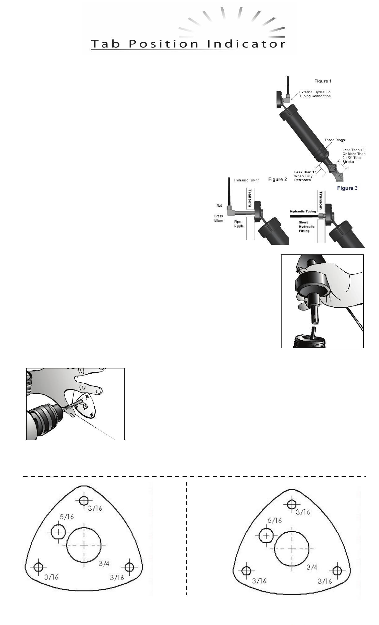
IF ACTUATOR STROKE IS LESS THAN 1" OR MORE THAN 2-1/2", OR IF LESS THAN 1"
OF PISTON SHAFT IS EXPOSED WHEN THE ACTUATOR IS FULLY RETRACTED, HAS
EXTERNAL HYDRAULIC CONNECTION, OR THREE RINGS MOLDED ON CYLINDER
BODY (SEE FIGURE 1), SPECIAL SENSOR COILS ARE REQUIRED. (CONTACT BENNETT
MARINE)
MAKE ALL ELECTRICAL CONNECTIONS WITH POWER OFF
TEST SYSTEM BEFORE PUTTING THE BOAT BACK IN THE WATER
Tools required:
1/2" & 7/16” Wrench
5/16" Drill Bit
2” Hole Saw
Installing New Upper Hinge with Sensor
Step 1 Inside transom, with tabs in full up position, locate trim tab
hydraulic line and detach tubing from brass elbow (some fluid will
drip out). While holding pipe nipples with vise grips, unscrew brass
elbow. Do this procedure for port and starboard cylinders (see
figure 2). If there is no pipe nipple visible inside the transom, you
have a short fitting connection (see figure 3), skip to step 2.
Step 2 Outside transom, snap white plastic clip on shaft protruding from bottom of cylinder.
Grasp cylinder body with both hands and unscrew counterclockwise from cylinder upper
hinge (a small amount of fluid will spill).
Step 3 Insert metal rod into piston, POINTED END DOWN. Make sure that the O-ring is in
place in new upper hinge with sensor coil. Screw new upper hinge onto cylinder while
keeping metal rod inserted into center of sensor coil. Red cable for port side and green cable
for starboard side. Tighten upper hinge hand tight. IMPORTANT: Use care when handling
sensor coils during assembly to avoid damaging wires.
Step 4 Remove upper hinge from transom and remove pipe nipple. If you have a short fitting
use a 7/16” wrench to remove it from the upper hinge.
Step 5 Remove plastic clip from piston and repeat steps 2 - 4 for the starboard cylinder.
Step 6 Using template, drill 5/16" hole in transom for the sensor cable. Screw pipe nipple into new actuator upper hinge.
Step 8 Inside transom, remove masking tape from pipe nipples. Carefully wrap Teflon tape around male threads of pipe
nipples. Holding pipe nipples with vise grips (to prevent them from turning) re-secure 90 degree elbows. Re-attach
hydraulic tubing, tightening nut finger tight. Snug nut with 1/2" wrench. Do not over-tighten. Note: If you have the short
fittings omit this step.
Teflon Tape
Wire Stripper
Electric Drill
Marine Grade Sealant
Jewelers Small Screw Driver
Vise Grips
Wire Cutter
Tighten nipple hand tight. Then, with vise grips, tighten two full turns . . .
NO MORE. If you have the short fitting, using a ½” wrench screw it in until the
fitting is snug, the shoulder of the fitting will just touch the plastic of the upper
hinge.
Step 7 Cover end of pipe nipple with masking tape. Apply sealant to actuator
upper hinge surface around pipe nipple, screw holes, and cable. Feed actuator
cable through 5/16" hole and secure actuator upper hinge to transom with
mounting screws. Grasp cylinder body with both hands and tighten (clockwise)
securely. Repeat for other side. Run cables to helm.
Page 2

Mounting Display
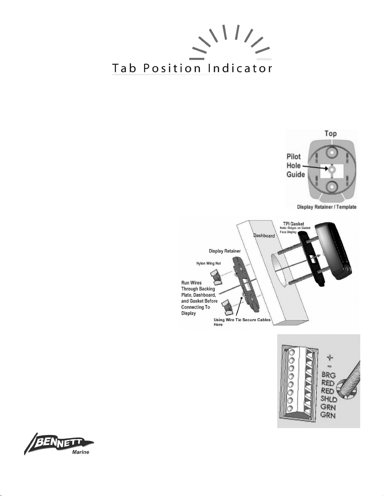
Step 1 Choose a location for the TPI display at the helm (or place in existing 2” gauge hole
if one is available). Make sure that there is no obstruction behind the dash in that location.
Using the Display Retainer / Template, drill a ¼” pilot hole. Remove the template, and snap
out the pilot hole guide by twisting it back and forth.
Step 2 Using the pilot hole
cut a 2” hole in the dash with
the 2” hole saw.
Step 3 Pull the Red and Green cables and Orange and Black
wires through the display retainer, dashboard and TPI gasket.
Step 4 Strip the two green wires
inside the green sensor cable
and insert into wire connector on
the back of the TPI display in
locations marked “GRN” (it does
not matter which green goes in
which GRN) and tighten in place
with small flat screwdriver. Repeat for red wires in red sensor cable and insert into locations
marked “RED”. Twist the silver shield wires together from both the red and green cables and
insert into location marked “SHLD”. Strip and insert the supplied black ground wire into
location marked “-“. Strip and insert supplied orange fused wire into location marked “+”. Make
sure that the fuse holder is closest to the power supply.
Step 5 Connect black wire from display to any convenient negative ground. Connect orange “+” wire from display to 12 volt
positive, such as ignition, accessories or gauges that turn on with ignition or a separate switch. Note: This power lead is
connected last. Use wire tie to secure wires to Display Retainer.
Step 6 Push display into hole, seating it on the gasket. Tighten wing nuts to secure display and retainer snugly to the
dashboard.
Calibration
Make sure that both trim tabs are in the full up position. When you power up the TPI the port and starboard displays will
begin to flash alternately, indicating that the system is not calibrated. Press and hold both buttons on the TPI
simultaneously for about 3 seconds. Both the port and starboard lower yellow LEDs will begin to blink. Using the Trim Tab
controls run both Trim Tabs to the full down position (Bow Down on the control). Hold the control longer then
necessary to ensure that both Tabs go fully down (this will not harm the system). A few moments after the Tabs are all
the way down the upper port and starboard yellow LEDs will begin blinking. Again, using the Trim Tab Controls, run both
tabs to the full up position. Make sure the tabs come all the way up. The upper yellow LEDs will then light up solidly
indicating that the TPI is calibrated and ready to operate. If you wish to re calibrate the TPI at any time simply bring the
Tabs to the full up position, hold both buttons down and repeat the calibration instructions.
Operation
The intensity of the display may be adjusted by pressing the right button to brighten and the left button to dim the display.
The TPI display may be turned off by pressing the left hand button until no display is visible.
Diagnostic Information
Port and starboard display alternately flash: TPI requires calibration. Refer to calibration information above.
Upper yellow LED flashes on port or starboard display: Indicates the display is not receiving a sensor signal. If the port
upper yellow LED flashes the fault is in the port sensor or wires. A flashing yellow LED on the starboard display would
indicate a fault on the starboard sensor or wiring. Check for a broken wire to sensor, faulty connection or corrosion at TPI
display. Switching the connections on the back of the helm display will confirm the diagnostic code if the flashing LEDs
switch sides. Alternatively you may check the twisted pair of wires inside the shielded red and green cables with an Ohm
meter set to the 10X scale. They should produce a reading in the 220 -260 Ohm range.
Bennett Marine
550 Jim Moran Blvd. Deerfield Beach, FL 33442 USA
Phone 954-427-1400 Fax 954-480-2897
Web Site www.BennettTrimTabs.com
E-mail info@BennettTrimTabs.com
Page 3
BRIDGE DISPLAY
INSTALLATION INSTRUCTIONS
READ INSTRUCTIONS COMPLETELY BEFORE BEGINNING INSTALLATION
Mounting Display
Step 1 — Choose a location for the TPI bridge display at the helm (or place in existing 2" gauge
hole if one is available). Make sure that there is no obstruction behind the dash in that location.
Using the Display Retainer / Template, drill a ¼" pilot hole. Remove the template, and snap out the
pilot hole guide by twisting it back and forth.
Step 2 — Using the pilot hole cut a 2" hole in the dash with the 2" hole saw.
Step 3 — Route 20' TPI bridge wire from upper TPI display location to lower TPI display.
Step 4 — At upper station pull TPI bridge wire through
the Display Retainer and hole in the dashboard. Strip the
red, black and white wires in the TPI bridge wire. Insert
and secure the red wire into the connection marked “+”,
the black wire into “-“ and the white wire into “BRG”. Twist
the silver shield, insert and secure it into the connection
marked “SHLD”. Take care that the shield wire is not
touching bare wires on any other connections.
Use wire tie to secure wires to Display Retainer.
Step 5 — Push display into hole, seating it on the
gasket. Tighten wing nuts to secure display and retainer
snugly to the dashboard.
Step 6 — Remove the lower station TPI display from the helm.
Step 7 — Strip the red, black and white wires in the 20' TPI bridge wire. Insert and secure
the white wire into the connection marked “BRG”. Insert and secure the red wire into the
connection marked “+”. The red TPI bridge wire will share this connection with the orange
power wire already installed at the lower display. Insert and secure the black wire into “-“.
The black TPI bridge wire will share this connection with the black ground wire already installed
at the lower display. Do not connect the silver shield wire to the lower display.
Step 8 — Reinstall lower TPI display.
Bennett Marine, Inc. • 550 Jim Moran Boulevard • Deereld Beach, Florida 33442 USA
Phone: (954) 427-1400 • Fax: (954) 480-2897 • Email: info@BennettTrimTabs.com • www.BennettTrimTabs.com
 Loading...