

Page 1

Installation Instructions
& Reference Guide
» READ INSTRUCTIONS COMPLETELY BEFORE BEGINNING INSTALLATION
» TEST SYSTEM BEFORE PUTTING BOAT IN WATER
» PLEASE KEEP THIS MANUAL WITH THE BOAT
550 Jim Moran Boulevard
Deereld Beach, Florida 33442
USA
Phone: +1.954.427.1400
Fax: +1.954.480.2897
Page 2
Congratulations, you are the owner of Bennett’s Premier SST System —
the most prestigious trimming system in the world. Bennett Marine is recognized
worldwide for durability, strength, and unparalleled customer satisfaction.
How to Use Your SST Trim Tab System
Getting and Staying Trimmed
Your vessel will “break over” or plane at a particular speed. This speed is
determined by weight distribution, water conditions, etc. Your SST trim tabs
enable you to plane at lower speeds. By depressing the helm control in the
“Bow Down” position, your trim tabs move down. This will raise your stern
and lower your bow, getting you up on plane faster and increasing your speed.
Your Vessel’s Optimum Attitude
Determine your optimum attitude by conducting this test: Get out and run at
full speed in calm water. Notice the bow in relation to the horizon. This should
be your best running attitude. You can use your trim tabs to recreate this “optimum
attitude,” correcting for changes in weight distribution, speed and water conditions.
Getting Used to the “Feel” of Your Tabs
When learning to use the SST, begin by pressing the helm control in half-second bursts,
allowing time between corrections for gradual trimming. Do not over-trim. An over-trimmed vessel
will “plow” or “bow-steer.” If you over-trim, simply press “BOW UP” and the bow will rise.
Trimming From a Bridge or Tower
When steering from a bridge or tower, a good trimming method is to watch the bow spray, stern wake, or the rooster tail. An untrimmed vessel will
produce spray farther aft of the bow and it will produce a larger wake. When trimmed, the bow spray is farther forward, the wake is reduced, and
the rooster tail is smaller and farther behind the boat. You’ll also notice that the engine RPM may increase when the boat is properly trimmed.
Running in Rough Water
When running in a chop, press “BOW DOWN”. This will bring the “V” of the hull in contact with the waves rather than having the waves pound the
atter portion of the hull and your passengers. In a following sea or when running an inlet, the trim tabs should be fully retracted for maximum
rudder response.
Correcting for a “Listing” Condition
The SST trim tabs may be operated individually so that you can correct for a “listing” condition. Your control is designed so that you can use it
“intuitively.” Do not think about what the trim tabs are doing, just concentrate on your bow. If the port bow is high, push the port-side “Bow Down”
direction. If the starboard bow is high, push the starboard side “Bow Down” direction until the “listing” condition is corrected.
Safety Precautions
• Do not over-trim, particularly at high speeds as the bow may dig in and wave action may cause the vessel to veer.
• While underway, do not move one trim tab signicantly farther down than the other as undesirable listing could occur.
• For best maneuverability, trim tabs should be fully retracted in a following sea, or when running an inlet.
• Improper use of trim tabs can cause an unexpected attitude change of vessel, which could lead to an unsafe condition.
The SST System will have a signicant eect on the operation and versatility of the vessel. The best learning method is to spend time getting
familiar with your vessel’s reaction to trim tabs. Always operate your vessel with safety rst in mind.
2
P-SST-S
Page 3
Installation Instructions for Dual Acting SST System
READ THIS FIRST BEFORE BEGINNING INSTALLATION
IMPORTANT FOR ACTUATOR INSTALLATION ON ALL BOATS
Actuators must be installed perpendicular to the trim tabs and parallel to each other. Stainless steel is not exible.
Measurements have to be precise.
BE CAREFUL NOT TO ROTATE THE ACTUATOR SHAFT ROTATING THE SHAFT WILL DAMAGE THE INTERNAL SENSOR.
IMPORTANT: FOR BOATS KEPT IN SEAWATER
THIS SYSTEM MUST BE PROTECTED FROM ELECTROLYSIS AND GALVANIC CORROSION —
THIS DAMAGE IS NOT COVERED UNDER WARRANTY
To provide protection from electrolytic corrosion a zinc anode must be applied to each tab. In the case of tabs installed on the
boat as original equipment by the builder, a bonding system may be utilized for your particular model. The SST system top
portion of the actuator and the actuator shaft are electrically isolated from each other. Therefore the trim plane and the
upper part of the actuator must be individually protected or integrated into a bonding system.
MUST USE ANTI-FOULING PAINT
Trim tabs and actuators should be painted with anti-fouling paint to prevent fouling by marine growth.
Follow paint manufacturer’s recommendations for proper priming and painting of stainless steel.
NOTE: Do not paint under zincs — this prevents electrical contact with trim tabs.
Step 1: Positioning Tabs
Position the trim tabs against the transom and check to see that the upper mounts of the hydraulic actuators do not center on an inside
obstruction. If they do, reposition tabs slightly outboard. The further outboard the tabs are mounted, the greater the lateral
(side-to-side) control. Position tabs 8-10 cm (3"-4") from the chine and run towards
the centerline of the boat.
Step 2: Securing Tabs
Attach the hinge plate and backing plate (mounting plates), and trim tab with
6mm (1/4") stainless steel fasteners along the bottom of the transom.
(See Figure 1) Using the backing plate as a template, mark screw hole locations.
Assemble mounting plates and tab, dip screws in marine epoxy before running in.
Support the trim tab from below, then slide trim tab between backing plate and hinge
plate before running screws tight. Snug screws down to secure mounting plates and
trim tab to transom. If the transom is curved, a shim must be made of a suitable
material to provide a at mounting surface.
7mm (9/32") Mounting Holes for
6mm (1/4") Fasteners
Hinge
Backing
Plate
Plate
Trim Tab
Figure 1
3
Page 4
Step 3: Drilling the Holes for Actuators
DUAL ACTUATOR SYSTEMS (2 ACTUATORS PER SIDE)
These systems consist of two actuators per trim tab — one with
sensor and one without sensor. The actuator with the red sensor wire
installs on the port side of the boat, and the actuator with the green
sensor wire on the starboard side of the boat.
IMPORTANT: The hole for the sensor wire must be accurate
— match the paper template exactly so that the wire goes
through the transom easily. Be careful not to crush or pinch
the wire while mounting the actuator.
(See Figure 2) For this step, use the two actuators WITHOUT the
sensor wires. You will do this for each side of the boat:
1. Each trim tab is installed as an extension of the hull. To achieve
this, position the upper mount of each actuator with the trim tab on
the same plane as the hull bottom.
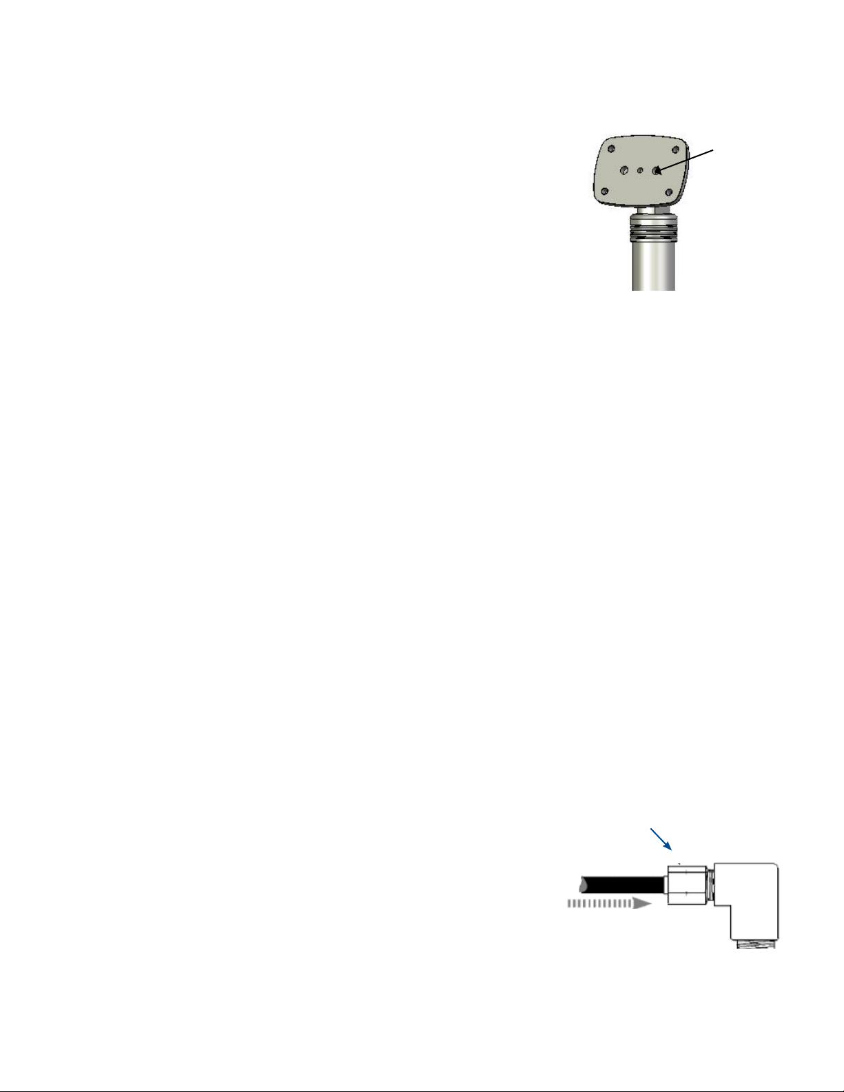
IMPORTANT INSTALLATION NOTICE:
MAKE SURE ACTUATOR UPPER MOUNTS
FACE THE CORRECT WAY
The upper mount is able to pivot through 180 degrees but there
is only one correct way to install it.
An easy guide: Make sure the three black dots in the upper
mount (as shown) are not visible when installed.
No black dots visible
when mounted.
CORRECT
Black dots visible.
NOT CORRECT
2. Support the trim tab assembly from below while positioning against the transom. Attach both actuators without sensors to the trim
tab using the supplied 5/16-18 x 1 ¼" hex head machine screws.
3. Mark the outline of the four mounting holes in the upper mount. Remove the actuators from the trim tab and set aside.
4. Take both actuator paper templates and put them in position — the paper template with sensor hole should be inboard, and the
template without sensor hole should be outboard. Align the templates and tape to the transom. The templates should be used to mark
and drill the sensor holes and pipe nipple holes. Drilling a small pilot hole rst helps locate an accurate center for each hole. Based on
the template, for the actuators with a sensor, drill a 19mm (3/4") hole in the transom for the sensor wire. Drill the marked
8mm (5/16") mounting holes for each actuator. And drill the marked 12mm (1/2") holes for the pipe nipples.
5. Once all the holes are drilled, mount the actuators to the trim plane using the supplied machine screws. DO NOT TIGHTEN.
Note: Actuators WITH sensors should
be mounted inboard. Actuators
WITHOUT sensors should be mounted
outboard.
PROCEED TO STEP 4 ON PAGE 6 TO
COMPLETE THE INSTALLATION.
For Each Side of the Boat:
Use Both Actuators
WITHOUT Sensors to
Position the Upper
Mounts and Drill the
Four Mounting Holes
Template
Without
Sensor
Use Individual Templates to
Drill the Sensor Holes and
Pipe Nipple Holes
Template
With Sensor
(inboard
actuator)
4
Figure 2
Page 5
SINGLE ACTUATOR SYSTEMS (1 ACTUATOR PER SIDE)
(The actuator with the red sensor wire installs on the port side of the boat,
and the actuator with the green sensor wire on the starboard side of the boat.)
1. Each trim tab is installed as an extension of the hull. To achieve this,
position the upper mount of each actuator with the trim tab on the same plane
as the hull bottom. Support the trim tab assembly from below in the fully
retracted position. Attach an actuator to the trim plane using the supplied
5/16-18 x 1 ¼" hex head machine screws. Tip back the upper mount such that
the wires and the hydraulic ports face away from the transom. Position the
assembly template over the end of the upper mount as shown in Figure 3.
The radius on the top of the uprights should nest fully into the assembly
template. This will temporarily locate the position of the upper mount.
Mark the position of the assembly template by tracing around the perimeter of
the template.
2. Remove the actuators from the trim tab and set aside.
Figure 3
3. Hold the assembly template placed in the marked position, then
mark the outline of the four mounting holes, the pipe nipple holes
and the sensor cable hole.
4. Remove the assembly template. When completed, you should
have an outline of the actuator upper mount as shown in Figure 4.
5. Drill the marked 8mm (5/16") mounting holes for each
actuator. Drill the 19mm (3/4") hole in the transom for the sensor
wire. And drill the 12mm (1/2") holes for the pipe nipples.
IMPORTANT: The hole for the sensor wire must be
accurate — match the template exactly so that the wire
goes through the transom easily. Be careful not to crush
or pinch the wire while mounting the actuator.
6. Once all the holes are drilled, mount the actuators to the trim
tab using the supplied 5/16-18 x 1 ¼" hex head machine screws.
DO NOT TIGHTEN.
Figure 4
IMPORTANT INSTALLATION NOTICE:
MAKE SURE ACTUATOR UPPER MOUNTS
FACE THE CORRECT WAY
No black dots visible
when mounted.
CORRECT
Black dots visible.
NOT CORRECT
5
Page 6
Step 4: Mounting the Actuators to the Transom
Carefully remove hex plugs from the uid holes in the actuator upper mounts. The actuators contain a large amount of automatic
transmission uid. Apply Teon tape on male threads of pipe nipples and tighten into the actuator upper mounts. (See Figure 5)
Note: Before pushing the pipe nipples and sensor plugs through the holes in the
transom, cover the ends with masking tape to prevent damage or debris from
entering the system.
Carefully insert sensor wire through center hole. Pull all slack sensor wire into the boat.
Pipe nipples
thread in here
with teon
tape
Apply waterproof sealant on surface of the upper mount, around pipe nipples and screw holes.
Insert pipe nipples through transom and secure actuator upper mounts to transom with
8mm (5/16") fasteners. Actuators should be through-bolted to transom.
Figure 5
Tighten 5/16-18 x 1 ¼" machine screws to attach the actuator to the trim tab.
Step 5: Filling the Dual Acting Hydraulic Power Unit (DAHPU)
Remove the Lexan cover from the DAHPU. Then remove the plug from the ller stack located at the front left corner of the reservoir.
Fill uid to reservoir if necessary using any type automatic transmission uid (ATF).
Step 6: Mounting the Dual Acting Hydraulic Power Unit
Install Dual Acting Hydraulic Power Unit (DAHPU) in a convenient, dry location. Important: The DAHPU must be mounted in a dry
enough location to avoid drenching. Allow space above the DAHPU so that it may slide into its mounting bracket — about
8 cm (3"). This will also be enough space to remove Lexan cover once installed. Use the mounting bracket as a template, being careful
not to ex or bend it. The upper holes on the DAHPU mounting bracket should be 11.75 cm (4 ⁄") apart. Drill 4mm (5/32") pilot holes for
the mounting bracket. Put the four #10 x 1" screws into place but do not fully tighten. Run ground wire and wire harness down the back of
the DAHPU while sliding it into bracket. Now tighten screws on mounting bracket.
Step 7: Attaching Fittings
Inside the transom, remove the protective tape from the pipe nipples. Check that the pipe nipples are clean and clear. Then apply Teon
tape on male threads of pipe nipples and tighten the 90° brass elbows to pipe nipples.
Step 8: Running Hydraulic Tubing
Single Actuator System: Run hydraulic tubing between the actuators and cut to length. Secure tubing as needed. (See next page,
Figure 7 for Single Actuator Systems.) Dual Actuator Systems: Run tubing from the DAHPUs to the desired Brass Line-T location as
shown. Secure as required. (See Figure 8 for Dual Actuator Systems.) Use tube bending clips at desired 90° bends in tubing to prevent kinking.
Step 9: Connecting Tubing to Actuators and DAHPUs
(See Figure 6) Insert tubing through the nut with ferrule and into the 90° elbow.
Push tubing to bottom of tting while tightening.
Tighten nut with 13mm (½") wrench one full turn past
nger tight - NO MORE.
Push until the tubing bottoms in the tting. While continuing to bottom the tubing in
the tting, tighten nut “nger tight,” then one full turn with a 13mm (1/2") wrench …
NO MORE. Do the same to connect the tubing to the Brass Line-Ts, and then from the Brass
Line-Ts to the DAHPUs.
Step 12: Installing Electronic Indicator Control
Wire control and electrical system per diagram and instructions in the next section for a
SST System with an EIC5000.
6
Page 7

RUNNING THE HYDRAULIC TUBING FOR SINGLE ACTUATOR SYSTEMS
Tabs
Up
Starboard DAHPU
Starboard Actuator
Starboard Side
of Boat
Tabs
Down
Tabs
Down
Tabs
Up
View from
Inside of
Boat
Transom
Figure 7
Tabs
Down
Port Side
of Boat
Tabs
Tabs
Up
Up
Port DAHPU
Port Actuator
Tabs
Down
Tabs
Down
RUNNING THE HYDRAULIC TUBING FOR DUAL ACTUATOR SYSTEMS
Starboard Side
of Boat
Tabs
Up
View
from
Inside of
Boat
Tabs
Up
Tabs
Down
Tabs
Down
Tabs
Up
View from
Inside of
Boat
Transom
Tabs
Down
Tabs
Up
Tabs
Up
Port Side
of Boat
Down
View
from
Inside of
Boat
Tabs
Tabs
Down
Tabs
Up
Starboard DAHPU
Starboard Actuators
Figure 8
Port DAHPU
Port Actuators
7
Page 8

System Schematic and Parts List for Dual Acting, Dual Station,
Dual Actuator SST System with Electronic Indicator Control
Item # Description Part #
1 EIC Display (Upper or Lower Helm) EIC001
2 EIC Bridge Wire Harness (thin gray) EIC801
3 EIC Wire Harness (thick gray) EIC301
4 EIC Bridge Box EIC701
1
Upper Helm
EIC Display
(Secondary)
5 EIC Wire Harness (blue) EIC201
6 EIC Relay Module* EIC102
7 EIC Power Cables Attached to EIC101
8 Port Dual Acting Relay Module* RMPORTDA24
9 Starboard Dual Acting Relay Module* RMSTBDDA24
10 EIC Dual Pump Cable (Y-Harness) EICWH10101
11 Dual Acting Hydraulic Power Unit* DAHPU2
*Parts also available for 12 Volt systems.
+
Contact Premier@BennettTrimTabs.com
for parts and pricing.
-
6
(-) Ground
11
+
-
10 11
**
1
Lower Helm
EIC Display
(Primary)
3
5
**Shorter cable shown on #6 EIC Relay Module
7
is for optional Auto Tab Control (AC3000).
If no Auto Tab Control is installed, this cable is
not used.
Ground (-)
+
-
2
4
Stainless Steel
Actuators
Port
8
9
Stainless Steel
Actuators
Starboard
Stainless Steel
Trim Tabs
Page 9

Installation Instructions for Electronic Indicator Control (EIC)
Spare: For
Dual Station SST System
IMPORTANT: MAKE ALL ELECTRICAL CONNECTIONS WITH POWER OFF
SST Actuators with Sensor Wires should already be mounted per instructions on pages
4-6.
Step 1: Mounting the EIC Relay Module
(#6 on System Schematic on Page 8)
• Mount the EIC Relay Module in a dry location centrally located between the two
Dual Acting Hydraulic Power Units (DAHPUs).
Power Cables
Step 2: Mounting the Port and Starboard Dual Acting Relay Modules
(#8 and #9 on System Schematic)
• Mount the Port Dual Acting Relay Module (Red Collar on the Connector) near the port DAHPU.
• Mount the Starboard Dual Acting Relay Module (Green Collar on the Connector) near the
starboard DAHPU.
• Attach the black wires to battery ground. Attach the orange wires with inline fuse
to the same battery positive power source. The orange wires will supply power to
Port Sensor
Wire Connector
the DAHPUs — make sure that the power source is rated for 10 amps (24V) or 20 amps (12V).
Step 3: Connecting the Y-Harness
(#10 on System Schematic)
• Connect the “Y-Harness” to the longer of the two cables on the EIC Relay Module.
Note: The shorter cable coming out of the EIC Relay Module is for the optional
Auto Tab Control (AC3000). If no Auto Tab Control is installed this cable is not used.
• Connect the Y-Harness plug with the Red Collar to the Port Dual Acting Relay Module plug (red to red).
Optional Auto
Tab Control
Starboard Sensor
Wire Connector
Connects to
EIC Display
Grounding Stud
DO NOT CONNECT TO DAHPUs
EIC Relay Module
Figure 9
Connects to
Y-Harness
• Connect Y-Harness plug with the Green Collar to the Starboard Dual Acting Relay Module plug (green to green).
Step 4: Connecting the DAHPU
(#11 on System Schematic) Wire Harnesses to the Port and Starboard Dual Acting Relay Modules
• Connect the Port DAHPU Wire Harness to the Port Dual Acting Relay Module.
• Connect the Starboard DAHPU Wire Harness to the Starboard Dual Acting Relay Module.
Step 5: Connecting the DAHPU ground wire
• Run the black ground wire from the back of each Dual Acting Hydraulic Power Unit
(#11 on System Schematic) to
the vessel’s 24V or 12V battery ground system.
• DO NOT connect to EIC Relay Module grounding stud. (See Figure 9 above)
Step 6: Connecting the Sensor Wires
• Plug the Green Sensor Wire into the Starboard Sensor Wire Connector (green collar) on the EIC Relay Module
• Plug the Red Sensor Wire into the Port Sensor Wire Connector (red collar) on the EIC Relay Module
Step 7: Mounting the EIC Display at the Helm
(#1 on System Schematic)
(#6 on System Schematic).
Follow these instructions for both the Lower Helm and Upper Helm EIC Displays
• Using the enclosed paper EIC Display Template, mark the location for your EIC Display and
locate the centers of the holes on the template.
• Use a 51mm (2") hole-saw to cut the center hole and 5mm (3/16") drill for the four
mounting stud holes.
(#6 on System Schematic).
9
Page 10

• Use a small bead of sealant around the perimeter of the display to seal.
• Using the 4 nylon thumb-nuts, secure the display. (Do not over-tighten.)
NOTE: IF YOU HAVE A SINGLE STATION SYSTEM, JUMP TO STEP 13.
Step 8: Mounting the EIC Bridge Box
(#4 on System Schematic)
• Mount the EIC Bridge Box within the length of the thick gray EIC Wire Harness (Part# EIC301, #3 on System Schematic) that will plug
into the Lower Helm EIC Display.
Step 9: Connecting the EIC Wire Harness (Blue) to the EIC Bridge Box
• Plug the EIC Wire Harness
(Part# EIC201, #5 on System Schematic) into the EIC Relay Module (#6 on System Schematic).
• Plug the other end of the Blue EIC Wire Harness into ANY of the three connectors on the Bridge Box.
• The cable must be properly strain relieved at both ends to support the weight of the blue cable at the Bridge Box.
Step 10: Connecting the Upper Helm EIC Display (secondary) to the EIC Bridge Box
• Plug the thin gray EIC Bridge Wire Harness
(Part# EIC801, #2 on System Schematic) into the back of the Upper Helm EIC Display.
• Plug the EIC Bridge Wire Harness into ANY of the three connectors on the Bridge Box.
• The cable must be properly strain relieved at both ends to support the weight of the cable at the Bridge Box.
Step 11: Connecting the Lower Helm EIC Display (primary) to the EIC Bridge Box
• Plug the thick gray EIC Wire Harness
(Part# EIC301, #3 on System Schematic) into the back of the Lower Helm EIC Display.
• Plug the EIC Wire Harness into the remaining connector on the Bridge Box.
• The cable must be properly strain relieved at both ends to support the weight of the cable at the Bridge Box.
Step 12: Cutting the Wiring for Upper Helm EIC Display (secondary)
• DO NOT connect the orange and purple wires at the Upper Helm EIC Display. Cut the orange and purple wires o the display.
GO TO STEP 14.
FOR SINGLE STATION SYSTEM ONLY
Step 13: Running the EIC Wire Harness
(Part# EIC201, #5 on System Schematic)
• Plug the EIC Wire Harness (Blue Cable) into the back of the EIC Display and run to the location of the EIC Relay Module.
• Plug the Blue EIC Wire Harness into the EIC Relay Module.
• The cable must be properly strain relieved at both ends to support the weight of the blue cable.
GO TO STEP 14.
FOR BOTH DUAL AND SINGLE STATION SYSTEMS
Step 14: Connecting the Wiring for the Lower Helm EIC Display (primary)
• Connect the Purple wire containing the inline 1.5 amp fuse to the ignition switch or any 24 or 12 volt circuit that turns on with the
ignition. This wire is used to initiate Auto Tab Retraction when the ignition is switched to the o position.
• Connect the Orange wire containing the inline 1.5 amp fuse to a source that supplies power to the boat’s electronics and/or gauges.
This wire senses the power and shuts o the display when the helm power is shut o.
Step 15: Connecting the Power and Ground on the EIC Power Cables
(#7 on System Schematic) to the EIC Relay Module
• Attach the black wire to battery ground. Attach the orange wire with inline fuse to the same battery positive power source.
10
Page 11

Calibration and Operation
Once installation of the SST System is complete, use the EIC to bleed the system by holding down the “BOW DOWN” position for
15 seconds, then “BOW UP” for 15-20 seconds. Repeat 3 times. This will purge air from the system. Then place both tabs in the “full
down” position and check all hydraulic connections for leaks. Bring the tabs to the full UP position and check the uid level. Add ATF if
necessary. Also check for leaks in the “UP” position.
Calibration — NOTE: Calibration must be done at the Lower Helm EIC Display
1. The port and starboard
calibrated.
2. Press and hold the “sun” and “moon” buttons on the Lower Helm EIC Display
simultaneously for approximately 3 seconds. Both the port and starboard lower
will begin to ash. Release the “sun” and “moon” buttons.
3. Using the Lower Helm EIC Display, run both trim tabs to the full down position
(BOW DOWN on the control). Make sure the tabs go all the way DOWN by holding the buttons
for at least 15 seconds. (Holding the buttons after the tabs are down will not harm the system).
4. A few seconds after the tabs are all the way down the port and starboard upper
the Lower Helm EIC Display, run both tabs to the full up position (BOW UP on the control). Make sure the tabs come all the
way UP by holding the buttons for at least 15 seconds.
5. The upper and lower
wish to recalibrate the EIC at any time, simply bring the tabs to the full up position, press and hold the “sun” and “moon”
buttons down and repeat the calibration instructions.
Operation
The intensity of the display LEDs may be adjusted by pressing the “sun” button to brighten and the “moon” button to dim the display.
red LEDs will ash alternately, indicating that the system is not
yellow LEDs
Moon Button Sun Button
yellow LEDs will begin ashing. Again, using
yellow LEDs will then light up solidly, indicating that the EIC is calibrated and ready to operate. If you
EIC Display Diagnostic Information
Port and starboard red LEDs alternately ash: EIC requires calibration. Refer to calibration information above.
Upper
yellow LED ashes the fault is in the port sensor or wires. A ashing yellow LED on the starboard side would indicate a fault on the
starboard sensor or wires. Switching the sensor connections on the EIC Relay Module will conrm the diagnostic code if the ashing LEDs
switch sides. If the problem switched sides, check the suspected faulty actuator with an Ohm meter at the EIC sensor cable plug. The
reading should be in the 220-260 Ohm range. If the sensor readings are good, check for faulty connections (corrosion or broken wires).
yellow LED ashes on port or starboard side: Indicates the EIC Display is not receiving a sensor signal. If the port upper
11
Page 12

Dual Acting SST System Troubleshooting Guide
Before proceeding with the tests below, verify that each orange power wire is connected to a live positive power source, and that the
fuses* are not blown. Make sure that each black wire has a good connection to ground.** After this is complete, conduct the tests below.
STEP 1A — Troubleshooting for Port DAHPU and Port Dual Acting Relay Module
Unplug the port Dual Acting Hydraulic Power Unit (DAHPU) from the Port Dual Acting Relay Module (RMPORTDA). Using a hot lead,
directly power the DAHPU plug as shown below:
Operation Reaction
Touch positive to Red and Blue Simultaneously Port trim tab up
Touch positive to Green and Blue Simultaneously Port trim tab down
If the port trim tab does not move when DAHPU is powered direct, then the port DAHPU or port actuator(s) are faulty. Contact Bennett Marine.
If the port trim tab still moves, plug the DAHPU back into the Port Dual Acting Relay Module (RMPORTDA). Unplug the RMPORTDA
from the EIC Dual Pump Cable (Y-Harness). Take the RMPORTDA and using a hot lead directly power the three-color wire pigtail
featuring a red heat shrink collar as shown below:
Operation Reaction
Touch positive to Red and Blue Simultaneously Port trim tab down
Touch positive to Red and Yellow Simultaneously Port trim tab up
If the port trim tab does not move when powered through the Port Dual Acting Relay Module, then the RMPORTDA is faulty.
STEP 1B — Troubleshooting for Starboard DAHPU and Starboard Dual Acting Relay Module
Unplug the starboard Dual Acting Hydraulic Power Unit (DAHPU) from the Starboard Dual Acting Relay Module (RMSTBDDA). Using
a hot lead, directly power the DAHPU plug as shown below:
Operation Reaction
Touch positive to Red and Blue Simultaneously Starboard trim tab up
Touch positive to Green and Blue Simultaneously Starboard trim tab down
If the starboard trim tab does not move when DAHPU is powered direct, then the starboard DAHPU or starboard actuator(s) are faulty.
Contact Bennett Marine for assistance.
If the starboard trim tab still moves, plug the DAHPU back into the Starboard Dual Acting Relay Module (RMSTBDDA). Unplug the
RMSTBDDA from the EIC Dual Pump Cable (Y-Harness). Take the RMSTBDDA and using a hot lead directly power the three-color wire
pigtail featuring a green heat shrink collar as shown below:
Operation Reaction
Touch positive to Green and Blue Simultaneously Starboard trim tab down
Touch positive to Green and Yellow Simultaneously Starboard trim tab up
If the starboard trim tab does not move when powered through the Starboard Dual Acting Relay Module, then the RMSTBDDA is faulty.
* This system could contain up to ve (5) fuses — three (3) 1.5 amp, with two (2) 10 amp (24V) or two (2) 20 amp (12V). The boat builder could
have replaced these fuses with breakers, or used breakers and inline fuses.
** There are ve (5) ground (black wires) — two (2) DAHPUs, two (2) Dual Acting Relay Modules and one (1) EIC Relay Module.
12
Page 13

STEP 2
Before proceeding with the tests below, verify that each orange power wire is connected to a live positive power source and that the
fuses* are not blown. Make sure that each black wire has a good connection to ground.** After this is complete, conduct the tests below.
If the trim tab(s) is still operational after conducting the tests in Step 1, then either the Y-Harness or EIC Relay Module is at fault.
Perform the test below by removing the EIC Dual Pump Cable (Y-Harness) from the EIC Relay Module. Using a hot lead, directly
power the end of the Y-Harness just removed from the EIC Relay Module (four wires in the plug) as shown below:
Operation Reaction
Touch positive to Red and Blue Simultaneously Port trim tab down
Touch positive to Red and Yellow Simultaneously Port trim tab up
Touch positive to Green and Blue Simultaneously Starboard trim tab down
Touch positive to Green and Yellow Simultaneously Starboard trim tab up
Touch positive to Red, Green and Blue Simultaneously Both trim tabs down
Touch positive to Red, Green, and Yellow Simultaneously Both trim tabs up
If the trim tab(s) is still not operational when powered through the Y-Harness, then the Y-Harness is faulty.
If both trim tabs operate as they should after conducting the above test, then the EIC Relay Module may be faulty.
Conduct the following test by directly powering the shorter, unused cable on the EIC Relay Module:
Operation Reaction
Touch positive to Red and Blue Simultaneously Port trim tab down
Touch positive to Red and Yellow Simultaneously Port trim tab up
Touch positive to Green and Blue Simultaneously Starboard trim tab down
Touch positive to Green and Yellow Simultaneously Starboard trim tab up
Touch positive to Red, Green and Blue Simultaneously Both trim tabs down
Touch positive to Red, Green, and Yellow Simultaneously Both trim tabs up
If the trim tab(s) is still not operational when powered through the EIC Relay Module, then the EIC Relay Module is faulty.
If both trim tabs operate properly when the above test is conducted, then either the EIC Display or the EIC Wire Harness is at fault.
Ensure that both ends of the EIC Wire Harness are seated rmly in the plugs, and that the EIC Display’s orange wire has proper voltage.
* This system could contain up to ve (5) fuses — three (3) 1.5 amp, with two (2) 10 amp (24V) or two (2) 20 amp (12V). The boat builder could
have replaced these fuses with breakers, or used breakers and inline fuses.
** There are ve (5) ground (black wires) — two (2) DAHPUs, two (2) Dual Acting Relay Modules and one (1) EIC Relay Module.
13
Page 14

The Most Prestigious Trimming System in the World
Two Other Systems are Available in the Premier Line:
For vessels from 9 m (30 ft) to 14m (45 ft)
Not recommended for racing boats
High-Perfomance
Luxury Motor Yacht
Powerboats
BXT
14
For vessels from 12 m (40 ft) to 21 m (70 ft)
Military/Patrol
Page 15

Optional Auto Tab Control
Get a Perfectly Trimmed Vessel — Every Time
Bennett pioneered the Auto Tab Control (ATC) to make the boater’s experience on the water even better. It easily connects with the SST System by
plugging directly into the EIC Relay Module. It does exactly what it says it does — interacting with the SST System to automatically monitor your
vessel’s position and maintain the optimum cruising attitude.
Plug-N-Play:
Now with Fewer Components
The original ATC won the coveted Innovation of the Year Award from the
National Marine Manufacturer’s Association, the largest marine industry
association in the United States. The new version of the ATC, the AC3000, oers
the same benets with an easier installation. It incorporates new technology
that allows it to be more compact, with fewer components.
best running attitude possible for the
HOW IT WORKS
The Auto Tab Control maintains the
boat by automatically adjusting the
trim tabs to changes in vessel speed,
sea conditions and shifting weight.
Major Benets Include:
Fuel Savings: A properly trimmed vessel can signicantly reduce fuel costs by
15%. The ATC not only monitors and trims the boat, it does it more frequently and
accurately than a human.
Optimized Ride: When weight shifts, speed changes, winds shift, or water
conditions change, the ATC system adapts and corrects. It provides the best ride
that can be achieved with the vessel.
The ATC calculates and analyzes
attitude readings more than a
thousand times per second.
It learns and stores the vessel’s
characteristics in its memory and
uses this information for precise trim
tab corrections. Since it averages the
readings, it won’t over-correct in rough
water or momentary weight shifts.
The operator sets the vessel’s optimum
running attitude as the Zero Point. The
ATC retains this attitude in memory.
No Guesswork: The ATC monitors and maintains the optimal cruising attitude.
The captain can spend less time operating the trim controls.
As long as the trim tabs are of correct
size and the speed is adequate, the ATC
will recreate the programmed attitude
regardless of changing conditions.
15
Page 16

Bennett Marine SST System Warranty
Bennett Marine warranties the equipment that is sold and supplied against any faulty
manufacturing defects.
1) Warranty validity period:
a. The warranty period is twelve (12) months starting from the date of the rst use by
the original consumer. In the event that our systems are mounted or used on work or
commercial boats the warranty period is six (6) months from the date of rst use. The
manufacturer has the right to require from the client proof of the date specied on the
warranty request.
b. This period is neither extended nor interrupted through legal or amicable claims on
the part of the client. At the end of this period, the warranty is terminated without
further consideration.
c. The warranty will not be renewed following replacement or if the item is resold.
2) Conditions that make the warranty null and void:
a. The obligation of the warranty will not apply in case of negligence, faulty
installation or maintenance, operator’s responsibility, imprudence, non-observance
of recommended operating instructions, incidents resulting from a cause of force
majeure, or the use of automatic transmission uid of insucient quantity for this
equipment.
b. The warranty is not valid where some of Bennett components are installed on a
control system together with other manufacturers’ products.
c. The warranty does not apply if the faulty equipment is not returned to Bennett
Marine and if it has been previously disassembled, repaired, modied by either the
user or by a third party.
c. The defective products must be sent pre-paid together with a copy of the invoice or
vessel’s bill of sale.
d. In case the repairs are not under warranty as specied in the condition paragraph 2,
the owner agrees to pay the boat repair yard for said work, labor and materials. Verbal
price quotes by personnel are rough estimates and are not binding; all orders must be
in writing and signed by the owner and the manufacturer or distributor.
e. During the warranty period, the dismantling, repairing and reassembly of the faulty
items are the responsibility of Bennett Marine. The shipping costs for repaired or
replaced products, as well as for hauling and labor costs shall be paid by the client.
f. All work performed on vessels can only occur with Owner’s specic instructions.
However, in emergency cases, Bennett Marine reserves the right to repair Owner’s
vessel if in the opinion of Bennett Marine or our distributor an emergency arises
making such action necessary in the protection of the vessel. Owner agrees to pay for
these emergency repairs at the prevailing rates.
g. Bennett Marine reserves all rights against the vessel and personally against the
owner for payment of all charges in full.
h. Bennett Marine shall not be responsible for any damage to said vessel or damage
to or loss of any articles or personal property, gear, or any other appurtenances left
aboard the vessel.
i. Bennett Marine does not provide insurance for the vessel; the insurance liability
coverage is for Bennett Marine only. Owner agrees that he will provide his own
insurance for his vessel and will keep coverage in eect for the time period the vessel
is being repaired.
4) General warranty terms
d. The warranty does not cover failure due to the construction or choice of unsuitable
materials by ordering the product in spite of prior advice or as standard guidelines,
given by Bennett Marine.
3) Conditions of equipment failure
a. In case of equipment failure within its warranty period, Bennett Marine must be
contacted to authorize any replacement parts. The client must allow the technician
to be able to ascertain the defects and to perform corrective actions. After receiving
proper notication of the equipment defect, the technician shall correct this fault as
soon as reasonably possible, reserving the right, if applicable, to modify all or part of
the equipment in order to fulll the obligations.
b. The replacement of the defective components under warranty condition is left to
Bennett Marine’s judgment.
a. The obligation of the warranty only applies if the defect appeared under normal
operating conditions stipulated for this type of vessel, or indicated by the statement of
purpose or intended use to the manufacturer in writing.
b. The components replaced under warranty must be returned to Bennett Marine as
they are no longer the owner’s property.
c. Bennett Marine reserves the right to change its models or parts without any
obligation to make the same alterations to any products previously manufactured.
d. The manufacturer will not be responsible for damage resulting from the client’s
non-compliance with any of the obligations dened above.
e. No claim may be made for compensation such as personal injury, damage to goods
other than those concerned in this document, operating losses, commercial damage or
loss of earnings.
Page 17

54.0mm
2.8
"
71.9mm
2.8
"
71.9mm
5
mm
3/16
"
2.1
"
50 - 54mm
2
"
54.0mm
2.1
"
54.0mm
2.8
"
71.9mm
2.8
"
71.9mm
5
mm
3/16
"
2.1
"
50 - 54mm
2
"
54.0mm
2.1
"
EIC Display Templates
for Lower and Upper Helm Displays
Page 18

For SST Actuators WITH Sensors Only
8mm (5/16")
12mm
(1/2")
133.9mm (5.27
")
100.1mm
(3.94
")
60.5mm
(2.38
")
47.2mm
(1.86
")
95.3mm (3.75
")
19mm
(3/4")
8mm (5/16")
12mm
(1/2")
133.9mm (5.27
")
100.1mm
(3.94
")
60.5mm
(2.38
")
47.2mm
(1.86
")
95.3mm (3.75
")
19mm
(3/4")
Page 19

For SST Actuators WITHOUT Sensors Only
8mm (5/16")
12mm
(1/2")
133.9mm (5.27
")
100.1mm
(3.94
")
60.5mm
(2.38
")
47.2mm
(1.86
")
95.3mm (3.75
")
8mm (5/16")
12mm
(1/2")
133.9mm (5.27
")
100.1mm
(3.94
")
60.5mm
(2.38
")
47.2mm
(1.86
")
95.3mm (3.75
")
 Loading...