

Page 1
NMEA1 INSTALLATION INSTRUCTIONS
READ INSTRUCTIONS COMPLETELY BEFORE BEGINNING INSTALLATION
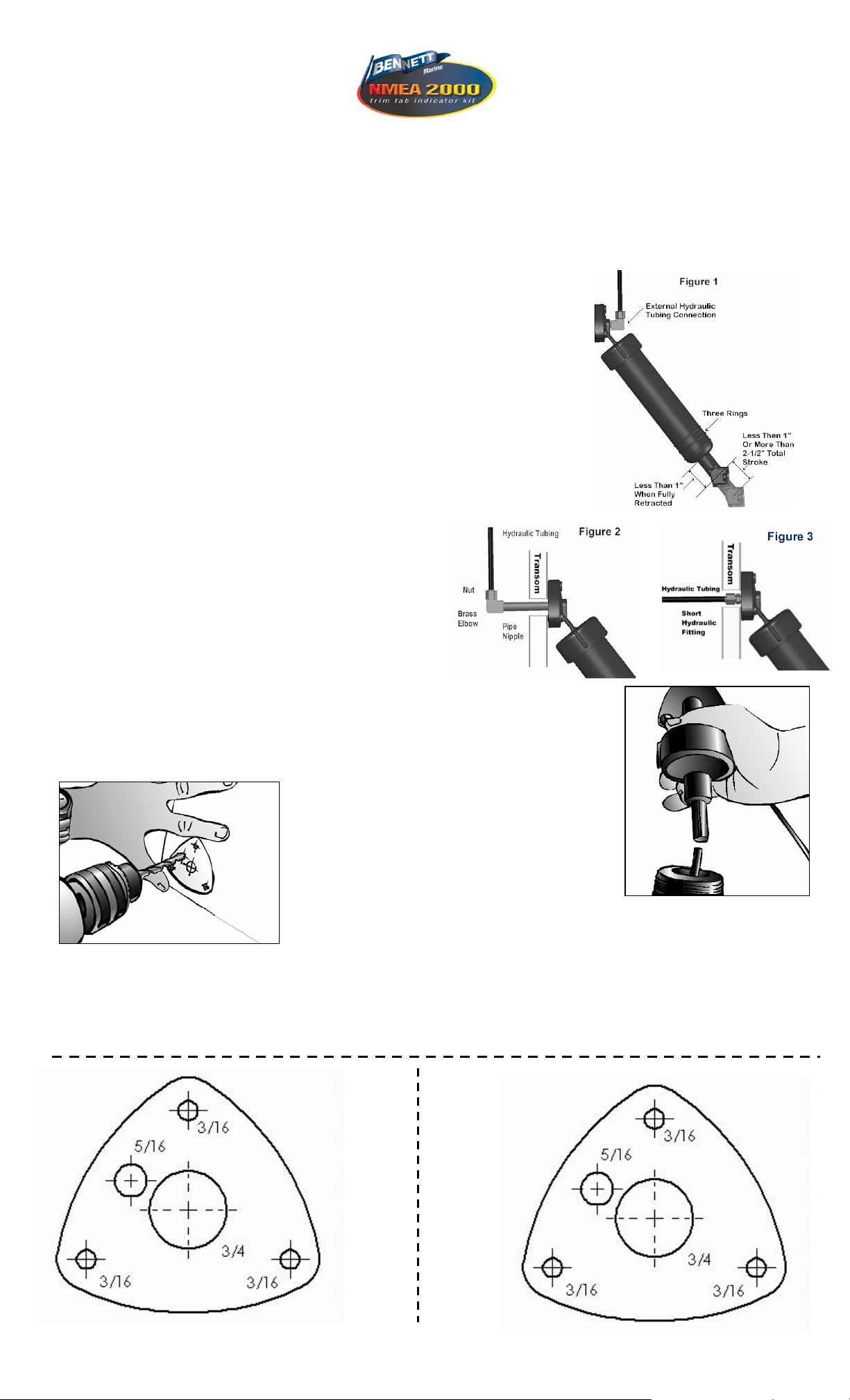
IF ACTUATOR STROKE IS LESS THAN 1" OR MORE THAN 2-1/2", OR IF LESS THAN 1" OF PISTON SHAFT IS EXPOSED
WHEN THE ACTUATOR IS FULLY RETRACTED, HAS EXTERNAL HYDRAULIC CONNECTION, OR THREE RINGS MOLDED
ON CYLINDER BODY (SEE FIGURE 1), SPECIAL SENSOR COILS ARE REQUIRED. (CONTACT BENNETT MARINE)
MAKE ALL ELECTRICAL CONNECTIONS WITH POWER OFF
TEST SYSTEM BEFORE PUTTING THE BOAT BACK IN THE WATER
Tools required:
1/2" & 7/16” Wrench
5/16" Drill Bit
Teflon Tape
Wire Stripper
Electric Drill
Installing New Upper Hinge with Sensor
Step 1 Inside transom, with tabs in full up position, locate trim tab hydraulic line and
detach tubing from brass elbow (some fluid will drip out). While holding pipe nipples
with vise grips, unscrew brass elbow. Do this procedure for port and starboard
cylinders (see figure 2). If there is no pipe nipple visible inside the transom, you have a
short fitting connection (see figure 3), skip to step 2.
Step 2 Outside transom, snap white plastic clip on shaft protruding from bottom of
cylinder. Grasp cylinder body with both hands and unscrew counterclockwise from
cylinder upper hinge (a small amount of fluid will spill).
Step 3 Insert metal rod into piston, POINTED END DOWN.
Make sure that the O-ring is in place in new upper hinge with
sensor coil. Screw new upper hinge onto cylinder while keeping
metal rod inserted into center of sensor coil. Red cable for port
side and green cable for starboard side. Tighten upper hinge
hand tight. IMPORTANT: Use care when handling sensor
coils during assembly to avoid damaging wires.
Step 4 Remove upper hinge from transom and remove pipe nipple. If you have a short
fitting use a 7/16” wrench to remove it from the upper hinge.
Step 5 Remove plastic clip from piston and repeat steps 2 - 4 for the starboard cylinder.
Step 6 Using template, drill 5/16" hole in transom for the sensor cable. Screw pipe nipple
(clockwise) securely. Repeat for other side. Run cables to helm.
Step 8 Inside transom, remove masking tape from pipe nipples. Carefully wrap Teflon tape around male threads of pipe
nipples. Holding pipe nipples with vise grips (to prevent them from turning) re-secure 90 degree elbows. Re-attach
hydraulic tubing, tightening nut finger tight. Snug nut with 1/2" wrench. Do not over-tighten. Note: If you have the short
fittings omit this step.
Marine Grade Sealant
Vise Grips
Wire Cutter
into new actuator upper hinge. Tighten nipple hand
tight. Then, with vise grips, tighten two full turns . . .
NO MORE. If you have the short fitting, using a ½”
wrench screw it in until the fitting is snug, the
shoulder of the fitting will just touch the plastic of the
upper hinge.
Step 7 Cover end of pipe nipple with masking tape.
Apply sealant to actuator upper hinge surface around pipe nipple, screw holes, and
cable. Feed actuator cable through 5/16" hole and secure actuator upper hinge to
transom with mounting screws. Grasp cylinder body with both hands and tighten
Page 2
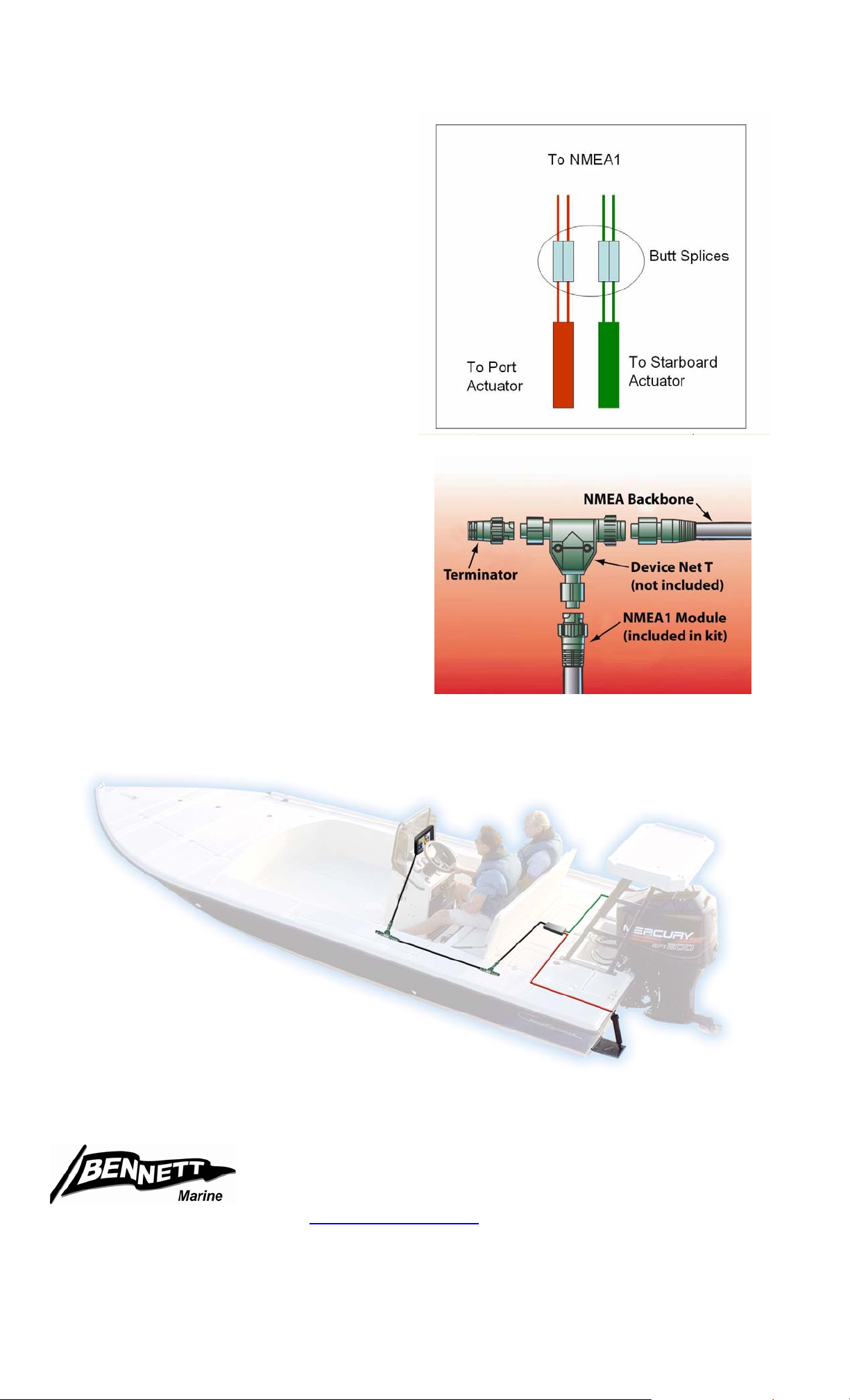
Wiring NMEA1 to NMEA2000 Backbone
1. Using red butt connectors,
splice the red and green wires
from sensors to the red and
green wires from the NMEA1
module. Note either red and
green wires from the sensor
may be spliced to either red or
green wire from the NMEA1
module.
2. Run the connection cable from
the NMEA1 Module to the
Backbone cable of your NMEA2000 system.
3. Connect the cable into the Backbone
using a red Device Net “T” (not included).
You will need to purchase this “T” or
buy an adapter to fit your current
NMEA2000 system. Please contact
your electronics manufacturer.
4. Make sure the Backbone system
has the correct terminator in place.
5. Your NMEA1 Trim Tab position
sensor is now installed. Refer
to the Lowrance, or other
electronics manufacturer’s
instructions for calibration of
the system.
Bennett Marine
550 Jim Moran Blvd. Deerfield Beach, FL 33442 USA
Phone 954-427-1400 Fax 954-480-2897
Web Site
E-mail info@BennettTrimTabs.com
www.BennettTrimTabs.com
 Loading...