

Page 1
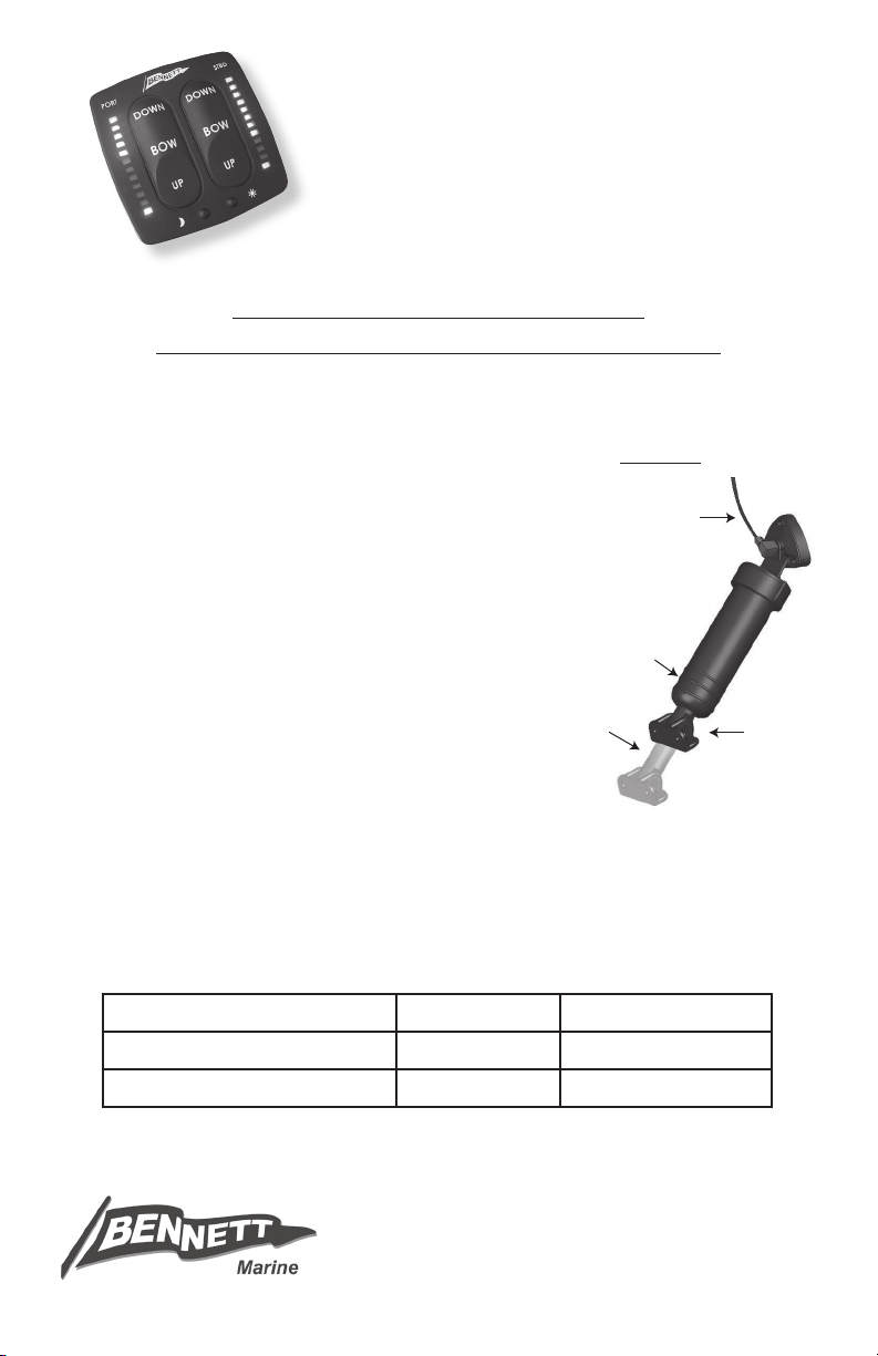
(EIC5000)
External Hydraulic
Tubing Connection
Three Rings
(cut rod only)
Less Than 1"
When Fully
Retracted
}
Less Than 1" or More
Than 2 ½" Total Stroke
}
ELECTRONIC INDICATOR CONTROL
INSTALLATION AND OPERATION
INSTRUCTIONS
BEFORE BEGINNING INSTALLATION:
READ INSTRUCTIONS COMPLETELY
MAKE SURE BATTERY POWER IS DISCONNECTED
TEST SYSTEM BEFORE PUTTING THE BOAT BACK IN THE WATER
IMPORTANT - SPECIAL REQUIREMENTS:
FIGURE 1
System is voltage specic. Please make sure •
you have a 12 or 24 volt EIC5000 depending
on your requirements.
(SEE FIGURE 1)•
Special sensor coils are required if:
- Actuator stroke is more than 2 ½" OR
- Less than 1" of piston shaft is exposed
when the actuator is fully retracted OR
- Actuator has external hydraulic connection
System will not work when actuator stroke is 1" or less•
If installing in an M80 or M120 Sport Tab kit, your actuator will have three molded rings as •
shown in Figure 1. Cut the metal rod to 6 ⁄" as indicated by score mark (see enclosed
instruction sheet for cutting the rod).
REQUIRED TOOLS
7/16", 1/2" & 9/16" Wrench Teon Tape Marine Grade Sealant
1/8", 3/16", 5/16" & 3/4" Drill Bit Wire Stripper Vise Grips
2" Hole Saw Electric Drill Wire Cutter
KEEP THIS MANUAL WITH BOAT OWNER’S INFORMATION
Bennett Marine, Inc.
550JimMoranBlvd•DeereldBeach,FL33442
Phone:954.427.1400•Fax:954.480.2897
Web: www.BennettTrimTabs.com
Page 2
IMPORTANT:
Hydraulic Tubing
Short
Hydraulic
Fitting
Transom
Transom
Hydraulic Tubing
Brass
Elbow
Nut
Pipe
Nipple
Check Special Requirements noted on the front cover of this manual before beginning installation.
If you are installing a preassembled actuator with the sensor wires already included, skip to step 6.
Installing New Upper Hinge with Sensor
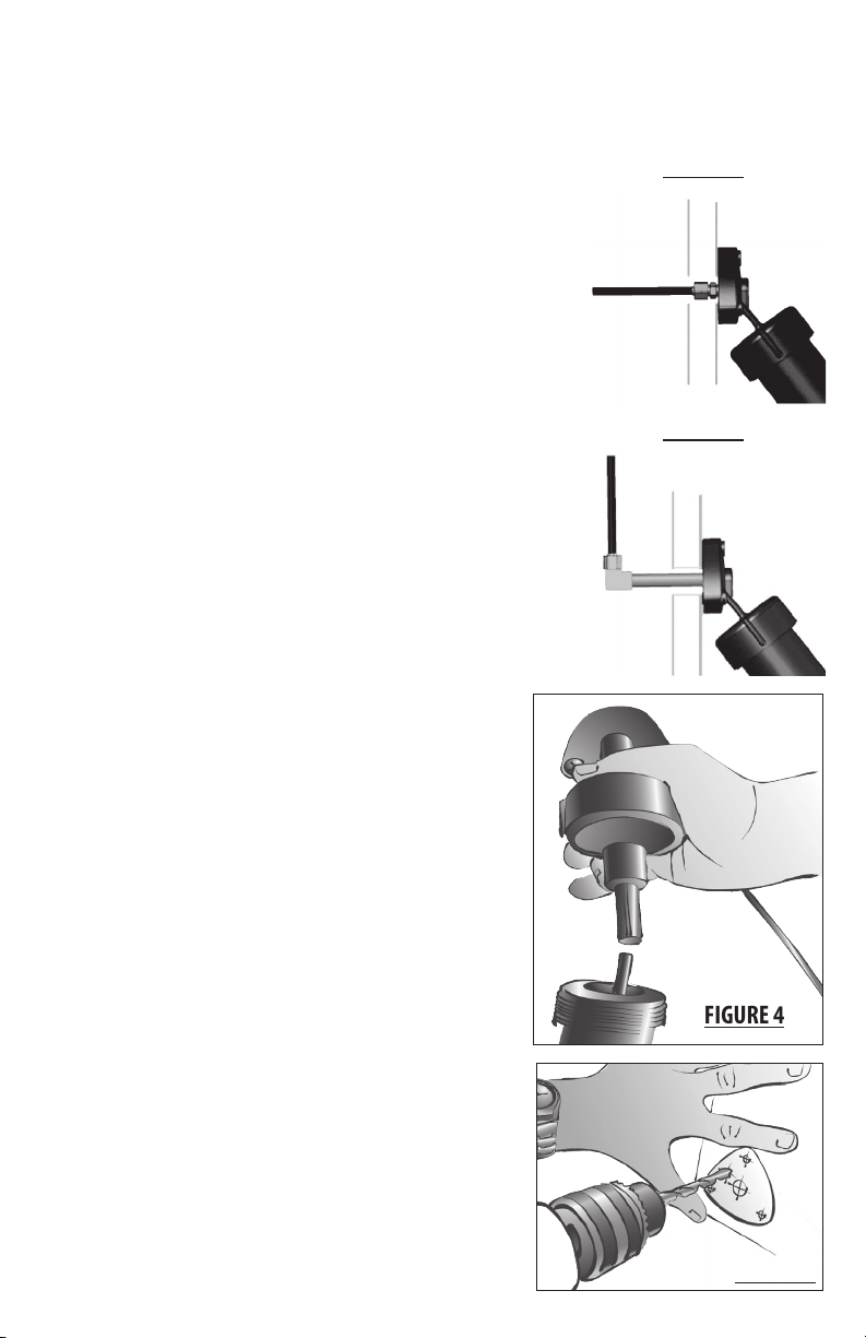
Step 1 - Inside transom, with tabs in full up position, locate
trim tab hydraulic line. If there is no pipe nipple visible inside
the transom, you have a short through-transom tting connection,
(see Figure 2). Unscrew and remove actuator away from the
transom and use a 7/16" wrench to remove the tubing from
the upper hinge. Skip to step 3.
For standard installations, detach tubing from brass elbow (some
uid will drip out). While holding pipe nipples with vise grips,
unscrew brass elbow using 9/16" wrench. Do this procedure for
port and starboard cylinders (see Figure 3).
Step 2 - Outside transom, unscrew and remove actuator away
from the transom. Remove pipe nipple.
Step 3 - Start with the port side cylinder. Snap white
plastic clip on shaft protruding from bottom of cylinder.
IMPORTANT: This clip must be used to keep the spring
inside the cylinder compressed. Grasp cylinder upper hinge
with both hands and unscrew it counterclockwise from the
cylinder body (a small amount of uid may spill).
FIGURE 2
FIGURE 3
Step 4 - IMPORTANT: Use care when handling sensor
coils during assembly to avoid damaging wires. Insert
metal rod into piston, POINTED END DOWN. Make sure that
the O-ring is in place in new upper hinge with sensor coil.
Screw new upper hinge with Red Sensor Wire onto the
port side cylinder while keeping metal rod inserted into
center of sensor coil (see Figure 4). Tighten upper hinge
hand tight. You will nish tightening cylinder in Step 7.
Step 5 - Remove plastic clip from piston and repeat steps
2 - 4 for the starboard cylinder. Use upper hinge with
Green Sensor Wire for the starboard side.
Step 6 - Using template on the last page, drill 5/16" hole
in transom for the Sensor Wire (see Figure 5). Screw pipe
FIGURE 4
FIGURE 5
Page 3
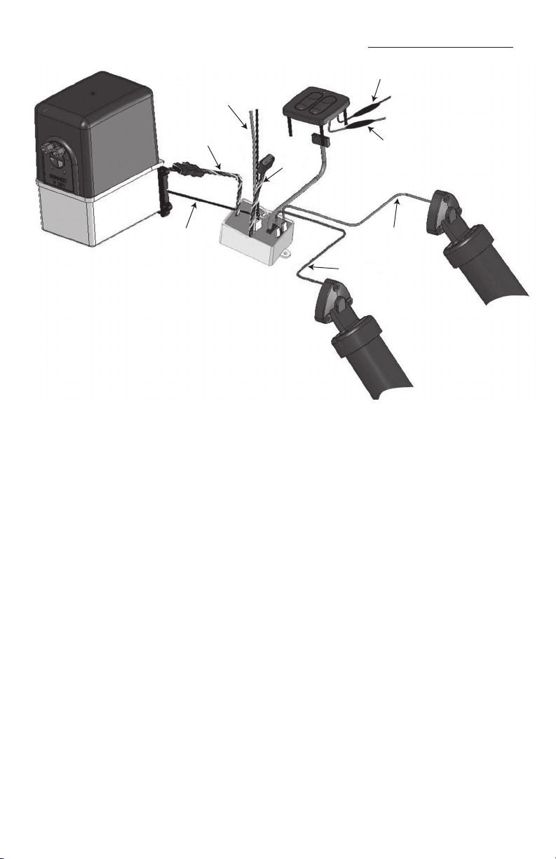
EIC Installation Overview
EIC Relay Module Power Lead
Orange (12 Volt +)
Black (12 Volt - )
Purple Power Lead
Orange Power Lead
Spare
ATC Lead
Starboard (Green)
Sensor Wire
Port (Red) Sensor Wire
Black Ground
Wire from HPU
Four-Color HPU
Wire Harness
EIC Relay Module
HPU
EIC Display
nipple into actuator upper hinge. Tighten nipple hand tight. Then, with vise grips, tighten two full
turns … NO MORE. Cover end of pipe nipple with masking tape. If you have the short throughtransom tting, using a 7/16" wrench, screw it in until the tting is snug; the shoulder of the
tting will just touch the plastic of the upper hinge.
Step 7 - Carefully feed Sensor Wire through 5/16" hole. Apply sealant to actuator upper hinge
surface around pipe nipple, screw holes, and cable. Secure actuator upper hinge to transom with
mounting screws. Grasp cylinder body with both hands and tighten (clockwise) securely.
Step 8 - Inside transom, remove masking tape from pipe nipples. Carefully wrap Teon tape
around male threads of pipe nipples. Holding pipe nipples with vise grips (to prevent them from
turning) re-secure 90 degree elbows. Re-attach hydraulic tubing, tightening nut nger tight.
Snug nut with 1/2" wrench. Do not over-tighten. Note: If you have the short through-transom
ttings, omit this step. Repeat for other side. Run Red and Green Sensor Wires to where you plan
to mount the EIC Module.
Step 9 - Mounting the EIC Display
Using the template on the last page, mark the location for your EIC Display and locate the centers
of the holes. Use a 2" hole-saw to cut the center hole and 3/16" drill for the four mounting stud
holes. Use a small bead of sealant around the perimeter of the display to seal. Plug the EIC Harness
(blue cable) into the back of the EIC Display. Use the 4 nylon thumb nuts to secure the display (use
care to avoid over-tightening).
Page 4

Step 10 - Mounting the EIC Relay Module
Connects to
HPU Harness
Spare: For
Optional Auto
Tab Control
Connects to EIC
Wire Harness
Starboard Sensor
Wire Connector
Port Sensor
Wire Connector
Attach Black Ground Wire from
Hydraulic Power Unit
Plug for
Power Connector
The Module is best located in a dry location close to the Hydraulic Power Unit. Use the mounting
hardware to secure it in place.
Step 11 - Running the EIC Wire Harness from the Display to the Module
Run the EIC Harness to the location you have selected for the EIC Relay Module. Plug the EIC Wire
Harness into the EIC Relay Module. The cable must be properly strain relieved and secured with
cable ties. For best results, create a drip loop.
Step 12 - Connecting the Wiring for the EIC
Purple wire with inline 1.5 amp fuse: Connect to ignition switch or any 12 volt circuit that
turns ON and OFF with ignition. This wire is used to initiate Auto Tab Retraction when the ignition
is switched to the OFF position. If Auto Tab Retraction is not desired this connection may be omitted.
Orange wire with inline 1.5 amp fuse: To source that supplies power to boat’s electronics and
or gauges. This wire switches the display system and must be installed.
Making Electrical Connections
(See Figure 6)
Ground wire from pump: Run the black ground
wire from the back of the hydraulic power unit to
the grounding stud on the Relay Module. Crimp
the supplied ring terminal on wire and secure with
10-32 hex nut.
FIGURE 6
HPU Connection: Plug the 4-color wire harness
from the Hydraulic Power Unit into the 4-color
output cable (longer of the two harnesses) on the
EIC Relay Module.
Sensor Wires: Plug Green Sensor wire into the
Green Wire Connector (starboard) on the
EIC Module. Plug Red Sensor Wire into the Red Wire
Connector (port) on the EIC Module.
Power Cable: Attach the black wire to 12 volt negative ground and the orange wire with inline
20 amp fuse to 12 volt positive source and plug into EIC Relay Module. Power source must be
capable of supporting 20 amps.
Auto Tab Control: (Shorter of two harnesses) This plug is used to interface a Bennett Auto Tab
Control into the EIC System. Please refer to Auto Tab Control Installation Instructions. If no Auto Tab
Control is installed this lead is not used.
Page 5

Calibration and Operation
Calibration – NOTE: If you have Upper and Lower Helm EIC Displays installed,
calibration must be done at the Lower Helm EIC Display.
Check trim tab system to ensure it is operational, then put both trim tabs in the FULL UP position
by holding down the “Bow Up” position.
The port and starboard 1. red LEDs will ash alternately, indicating that the system is not
calibrated.
Press and hold the sun and moon buttons on the EIC Display simultaneously for 2.
approximately 3 seconds. Both the port and starboard lower yellow LEDs will begin to
ash. Release the sun and moon buttons.
Using the EIC Display, run both trim tabs to the full down position (Bow Down on the control).3.
Make sure the tabs go all the way DOWN by holding the buttons down for at least
15 seconds or until the lower yellow LEDs stop ashing. (Holding the buttons after the tabs
are down will not harm the system).
A few seconds after the tabs are all the way down the port and starboard 4. upper yellow
LEDs will begin ashing. Again, using the EIC Display, run both tabs to the full up position
(Bow Up on the control). Make sure the tabs come all the way UP by holding the
buttons down for at least 15 seconds or until the upper yellow LEDs stop ashing.
The upper and lower yellow LEDs will then light up solidly, indicating that the EIC is 5.
calibrated and ready to operate. If you wish to recalibrate the EIC at any time, simply bring
the tabs to the full up position, press and hold the sun and moon buttons down and repeat
the calibration instructions.
Operation
The brightness of the display may be adjusted by pressing the sun button to brighten and the
moon button to dim the display.
Diagnostic Information
Port and starboard red LEDs alternately ash: EIC requires calibration. Follow steps above.
Upper yellow LED ashes on port or starboard side: Indicates the EIC Display is not receiving
a sensor signal. If the port upper yellow LED ashes, the fault is in the port (red) sensor or wires. A
ashing yellow LED on the starboard side would indicate a fault on the starboard (green) sensor or
wires. Switching the sensor connections on the EIC Relay Module will conrm the diagnostic code
if the ashing LED switches sides. If the problem switched sides, check the suspected faulty actuator
with an Ohm meter at the EIC sensor cable plug. The reading should be in the 220-260 Ohm range.
If the sensor readings are good, check for faulty connections (corrosion or broken wires).
Page 6

Electro-Hydraulic System Information
EIC Relay Module Fuse: 12 volt system uses 20 amp in-line fuse on positive, 24 volt uses 10 amp.
EIC Display Fuses: Both Purple and Orange wire fused at 1.5 amp for both 12 and 24 volts.
Hydraulic Power Unit and EIC Module Wiring
Red = Port Valve
Green = Starboard Valve
Yellow = Motor Reverse (pump retract)
Blue = Motor Forward (pump pressure)
Black on HPU = Connects to Ground Stud on EIC Module
Orange on EIC Module = Positive
Black on EIC Module = Ground (boat’s electrical system)
Troubleshooting
(This general information is not intended to be complete. Please feel free to contact Bennett Marine at
954.427.1400 or visit our website at www.BennettTrimTabs.com for additional information.)
If Trim Tabs do nothing, no movement, no sound from HPU:
Inspect 20 amp fuse on Orange wire at Relay Module and 1.5 amp fuse on Orange wire at display.
Inspect all wiring for disconnected or corroded connections.
HPU running but Trim Tabs do not move, or will go down but not retract:
Is the unit receiving a solid 12 volts to the EIC Module? Low voltage will sometimes cause the
solenoids to not open preventing the tabs from moving even though the pump motor is running.
Inspect all wiring for disconnected or corroded connections.
Conduct the following test using the “Spare for Auto Tab Control” connector at the EIC Module:
Operation = Reaction
Apply 12 volts (+)to blue, red = Port trim tab down
Apply 12 volts (+)to blue, green = Starboard trim tab down
Apply 12 volts (+)to blue, red, green = Both trim tabs down
Apply 12 volts (+)to yellow, red = Port trim tab up
Apply 12 volts (+)to yellow, green = Starboard trim tab up
Apply 12 volts (+)to yellow, red, green = Both trim tabs up
If the trim tabs function correctly for each wire grouping, then the Display or EIC Wire Harness is at
fault.
If the system does not function properly, then conduct the same test using the wire harness
connected to the HPU. If the trim tabs function correctly then the Module is faulty. If the trim tabs
do not function correctly, the HPU is at fault.
Page 7

2 1/8"
3/16"
2.83
2.83
2 1/8"
2
"
EIC Display Template
Ø 3/4
"
Ø 5/16
"
Ø 3/16
"
Ø 3/16
"
Ø 3/16
"
REVISIONS
ZONE
REV.
DESCRIPTION
DATE
Ø 3/4
"
Ø 5/16
"
Ø 3/16
"
Ø 3/16
"
Ø 3/16
"
REVISIONS
ZONE
REV.
DESCRIPTION
DATE
Upper Hinge Templates
Page 8

EIC5000 Electronic Indicator Control – Upper Helm
INSTALLATION AND OPERATION INSTRUCTIONS
READ INSTRUCTIONS COMPLETELY BEFORE
BEGINNING INSTALLATION
Step 1 Follow EIC5000 Installation Instructions to install system and Lower Helm EIC
Display.
Step 2 Mounting the Upper Helm EIC Display
Using the template, mark the location for your Upper Helm EIC Display and locate the
centers of the holes. Use a 2-1/8" holesaw to cut the center hole and 3/16" drill for
the four mounting stud holes. Use a small bead of sealant around the perimeter of the
display to seal. Using the 4 nylon thumb nuts secure the display (use care to avoid
overtightening).
Step 3 Mounting the Bridge Box
Mount the Bridge Box within 4 feet of the
Lower Helm EIC Display.
Step 4 Running the EIC Wire Harness from
Bridge Box to the EIC Relay Module
If you already have a Lower Helm EIC Display
installed, simply unplug the blue EIC Wire
Harness from the back of that Lower Helm
EIC Display and plug it into ANY of the three
connectors on the Bridge Box.
If this is a new installation, plug the blue EIC Wire Harness directly, connecting the EIC
Relay Module to any of the three connectors on the Bridge Box.
Step 5 Running the EIC Bridge Wire Harness to the Bridge Box
Plug the EIC Bridge Wire Harness into the back of the Upper Helm EIC Display, run it
down to the Bridge Box and plug it into ANY of the three connectors.
Step 6 Running the EIC 4-foot Wire Harness from the Lower Helm EIC Display to
the Bridge Box
Plug the 4-foot Wire Harness into the back of the Lower Helm EIC Display and plug into
the remaining connector on the Bridge Box.
Step 7 Connecting the EIC Display Wiring
The orange and purple wires at the Upper Helm EIC Display are NOT connected to any
power source. (They are connected at the Lower Helm EIC Display.)
Calibration
Refer to the EIC5000 Installation Instructions and calibrate system ONLY at the Lower
Helm EIC Display.
Page 9

EIC5000 Electronic Indicator Control – Upper Helm
INSTALLATION DIAGRAM
 Loading...