

Bennett Marine BOLT129, BOLT189, BOLT2412, BOLT249, BOLT1212 Installation & User Manual
...
IMPORTANT SAFETY INSTRUCTIONS: Read and save all instructions. This manual may periodically
be subject to change, for the most current version visit BennettTrimTabs.com/BoltManual.
Installation & User's Guide

Congrats!
Making an investment in Bennett Marine's durable and dependable
spectrum of products will keep you enjoying the boating experience
all the more. We've been a trusted name in the industry for over half a
century with exceptional products built to perform, and to last.
Get Bennett on board and enjoy the ride!
Behind You For The Distance
Bennett’s legendary customer service and support is a priceless perk to your new
purchase! Our expert sta with over 50 years of trim tab experience is ready to
assist with your installation, help with troubleshooting, or answer any other of
your questions along the way.
How to Contact Us
Call us at 1-954-427-1400, email Info@BennettTrimTabs.com, or go to
BennettTrimTabs.com/Contact and ll out the online form. Please allow 24 hours
for online requests. Our oce hours are Monday through Friday from 8:00 a.m.
to 5:00 p.m. (Eastern Standard Time).
The Benets of Trim Tabs
Increase Visibility For A Safer Ride: Keeping your bow down at reduced speeds is
important, especially in congested waters or foul weather. Bennett trim tabs enable
you to plane at a much lower speed, operating your boat more safely.
Save Money With Better Fuel Eciency: Getting up on plane quicker means
your boat spends less time running ineciently. Bennett trim tabs decrease engine
laboring, dramatically improving your fuel economy and prolonging the life of
the engine.
Maximize Performance While Smoothing Out e Ride: Bennett trim tabs
enhance the operating economy of your boat by lifting the stern in proportion to
speed, weight distribution, and fuel load changes.

Contents
Contacting Us .............................................................................................................. 2
Parts List & Specications
BOLT Trim Tab System Parts List .................................................................... 4
System Specications
....................................................................................... 5
Trim Tab Overview & Operation
How Trim Tabs Work ....................................................................................... 6
Special Conditions & Safety
........................................................................... 8
Installation Instructions
Actuator & Trim Tab Installation ..................................................................... 10
Helm Control Installation
................................................................................ 17
Relay Module Installation
............................................................................... 21
Extension Cable Installation
............................................................................. 22
Control Testing & Diagnostics
....................................................................... 23
System Wiring Diagrams & Installation Templates
.......................................... 24
General Maintenance & Safety Precautions
...................................................... 32
Troubleshooting
............................................................................................... 33
Warranty
Limited Warranty ............................................................................................ 38
Warranty Period
............................................................................................... 39
Bennett Marine | Bolt Electric Trim Tab System
4
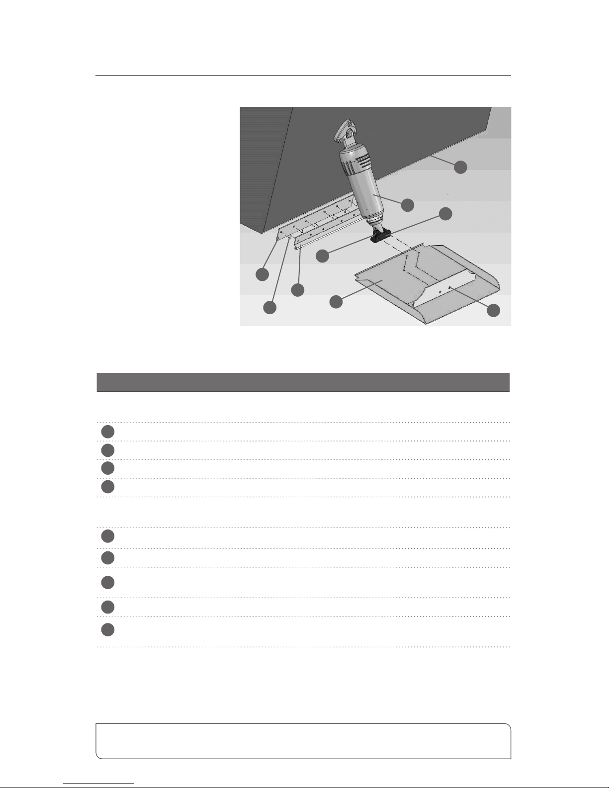
BOLT Electric Trim Tab System Parts
PART PART NO. QTY.
Items 1,2, & 3 make up a "Trim Plane Assembly" (TPA). TPA's are available for BOLT sets in the
standard sets listed above. Part numbers correspond to the tab size. Ex.TPA129, or TPA1212.
1
Trim Plane
2
2
Hinge Plate
2
3
Backing Plate
2
4
Complete Actuators
2
Standard Bolt sets include BEA2000 xed upper hinge actuators. BEA3000 adjustable upper
hinge actuators are available upon request.
5
Actuator Lower Hinge
A1113 2
6
Actuator Hinge Pin
A1115 2
7
Actuator Upper Hinge Screws
(#14 x 1-1/2")
H1174 6
8
Trim Tab Screws (#10 x 1-1/4")
EH1071
Varies
9
Actuator Lower Hinge Screws
(1/4-20 x 3/4" Phillips)
H1175 4
Helm controls sold separately. See page 17 for more information .
Standard Sets
• BOLT129
(12"x9" Tabs)
• BOLT189
(18"x9" Tabs)
• BOLT249
(24"x9" Tabs)
• BOLT1212
(12"x12" Tabs)
• BOLT1812
(18"x12" Tabs)
• BOLT2412
(24"x12"Tabs)
1
2
3
4
5
6
7
8
9

Bennett Marine | Bolt Electric Trim Tab System
5
System Specifications
Trim Planes
& Mounting Plates
Trim tab sizes vary. Stainless Steel, 304. Piano
hinge, bottom mount, and transom mount
available.
Actuators
2 models available:
BEA2000 Fixed Upper Hinge model:
Upper hinge material made of exible nylon.
Remainder of actuator is made of high impact
berglass-lled nylon. (12V or 24V)
BEA3000 Adjustable Upper Hinge model:
Made of high impact berglass-lled nylon.
Remainder of actuator is made of high impact
berglass-lled nylon. (12V or 24V)
Relay Module
Two types of relay modules with diagnostics
are available. (With ATR only, or with LED &
ATR, 12V or 24V).
Helm Control
Controls on 12 volt systems circuit breaker or
use 20 amp in-line fuse. (3 types of controls,
see page 18).
Communications
Junction Box
Used only for dual station and/or dual actuator
applications.
Helm controls sold separately. See page 17 for more information .
Bennett Marine | Bolt Electric Trim Tab System
6
How Trim Tabs Work
Bennett trim tabs most often attach to the bottom edge of the transom (although
other mounting variations are available). When the helm control is pressed,
the trim tabs move up or down. Water-force on the trim tab creates an upward
pressure, raising the stern and lowering the bow. Properly sized trim tabs improve
the performance of your boat in a wide range of weight, weather and water
conditions.
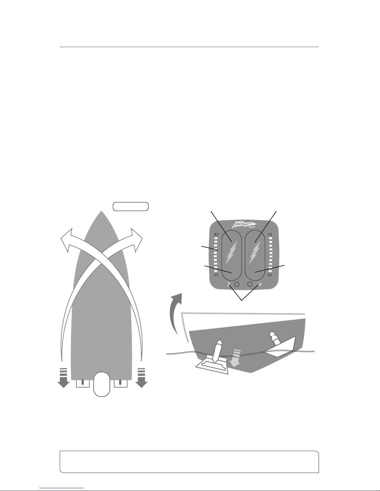
In general, trim tabs operate in reverse of what you may think (Figure 1). e port
(left) trim tab controls the starboard (right) bow. Conversely, the starboard (right)
trim tab controls the port (left) bow. e helm control is wired so that all you have
to do is press the control in the direction you want the bow to move. Don’t worry
about which trim tab is moving. e proper use of Bennett Trim Tabs becomes
second nature after a short time.
PORT
DOWN DOWN
UPUP
STBD
Stbd.
Tab
Port
Tab
Port Bow Stbd. Bow
Stbd.
Tab
When the port tab is lowered individually, an upward
force at the port stern of the boat is created. The
inverse applies when lowering the stbd. tab individually.
Figure 1
Lowers
Starboard
Bow
Raises
Starboard
Bow
Lowers
Port
Bow
Raises
Port
Bow
Pitch Correction
Roll Correction
Port
Tab
Controls the brightness of
the helm display LEDS
LEDs indicate
position of tabs

Bennett Marine | Bolt Electric Trim Tab System
7
continued How Trim Tabs Work
Getting and staying trimmed
Most boats break over (get on plane) at a particular speed. is speed is determined
by weight distribution, and water conditions, etc.. Bennett trim tabs enable your
boat to plane at speeds lower than the natural planing speed. By pressing the control
to the BOW DOWN position, your trim tabs move down. is will raise your stern
and lower your bow, getting you up on plane faster.
Optimum Attitude
A good way to nd your boat’s optimum attitude is to conduct a simple test.
Run the boat lightly loaded, at full speed on at water. Notice the bow in relation
to the horizon. is should be your boat’s best running attitude. Properly sized trim
tabs can be used to recreate this optimum attitude regardless of weight distribution,
speed or water conditions.
Getting Used to the Feel of Your Trim Tabs
When learning to use your tabs, begin by pressing the helm control in half second
bursts for gradual trimming. Be careful not to over-trim your boat. An overtrimmed boat will plow or bow-steer. If you over-trim the boat, simply press BOW
UP and the bow of the boat will rise.
Without trim tabs With trim tabs deployed

Bennett Marine | Bolt Electric Trim Tab System
8
Trim Tab Overview & Operation continued
Special Conditions & Safety Precautions
Correcting for a List
Bennett Trim Tabs may be operated individually so that you can correct for listing.
Your control is designed so that you can use it intuitively. Do not think about
what the trim tabs are doing, just concentrate on the bow. If the port bow is high,
push the port side BOW DOWN direction. If the starboard bow is high, push the
starboard side BOW DOWN direction. Press the control in half-second bursts to
avoid over-trimming, allowing time between corrections for the boat to react.
Using In Conjunction With Outboard Trim/Tilt
Using your trim tabs in conjunction with your engine’s power trim will
give you increased speed and power.
1. Adjust the trim tabs to achieve a planing attitude.
2. Use the power trim to position the prop path parallel to the water ow as
indicated by increased RPM / Speed.
3. If necessary, re-adjust the trim tabs to ne tune the trim of your boat.
In other words, use your trim tabs to trim the boat and your power trim to
trim your prop.
Running In Rough Water
When running in a chop or heavy seas, press BOW DOWN on both tabs. is will
bring the “V” of the hull in contact with the waves rather than having the waves
pound the hull and your passengers.
Following Sea
For maximum control and maneuverability in a following sea or when running in
an inlet, make sure the trim tabs are fully retracted by pressing BOW UP on both
tabs. is brings up the tabs, decreasing lift in the stern, allowing the bow to rise. If
tabs are deployed, the bow may dig.
Windy Chop
To raise the windward side of the boat press BOW UP on that side. If this is not
sucient, press BOW DOWN on the leeward side of the boat. is allows the
windward side of the boat to rise and minimizes spray. Do not overtrim when
attempting this.

Bennett Marine | Bolt Electric Trim Tab System
9
continued Trim Tab Overview & Operation
Shallow Water / Hole Shot
To lift the stern and lower the bow, lower both tabs completely down by pressing
BOW DOWN on both tabs. As you throttle up and speed increases, raise the tabs
by pressing BOW UP on both tabs.
Porpoising
Porpoising is a condition more common in faster boats. As speed increases, the
bow repeatedly rises out of the water until gravity overcomes lift and the bow
falls down. Press “Bow Down” in half second bursts. As the trim tabs deect, the
porpoising subsides and your speed should remain the same or decrease. Only a
slight amount of trim tab deection should be necessary.
Safety Precautions
Bennett trim tabs have a signicant eect on the operation and versatility of your
boat. No one knows your boat better than you, so the best learning method is to
spend time getting familiar with your boat’s reaction to the trim tabs. Remember,
practice makes perfect! As your experience increases, so will your enjoyment.
Always operate your boat with safety rst in mind.
• Do not over-trim, particularly at high speeds as the bow will dig in and wave
action may cause the boat to veer.
• While operating trim tabs, use caution. Improper use of trim tabs may cause
accidents and/or injury.
• For best maneuverability, trim tabs should be fully retracted in a following sea,
or when running in an inlet.
Bennett Marine | Bolt Electric Trim Tab System
10
Actuator & Tab Installation
Getting Started
• e actuator and tab installation must be done when the vessel is out of the
water. Do not attempt to install the actuators while the vessel is in the water as
the actuators and tabs are mounted below the water line.
• Before performing any electrical work on a vessel, disconnect the battery by
removing the positive (+) cable or if equipped, turn the battery disconnect
switch to the OFF position.
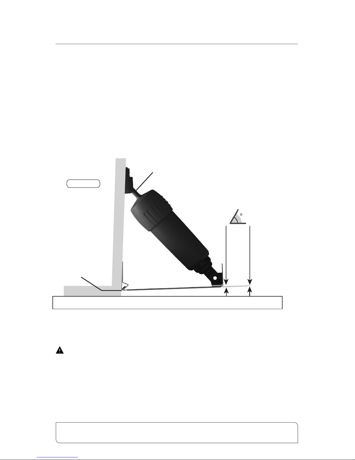
• Be sure to check for any obstructions: Before starting installation and drilling
any holes, verify that there are no mounting restrictions inside or outside the
transom. Choose a location about 3-4" from the chine (side of the hull). Hold
the tab up to the very bottom of the transom (1/8" from the hull bottom), and
hold the actuator on the trim tab. en set the actuator upper hinge against the
transom. Verify this for both sides so that the actuators will not center on any
obstruction. If they do, reposition tabs slightly inboard or outboard.
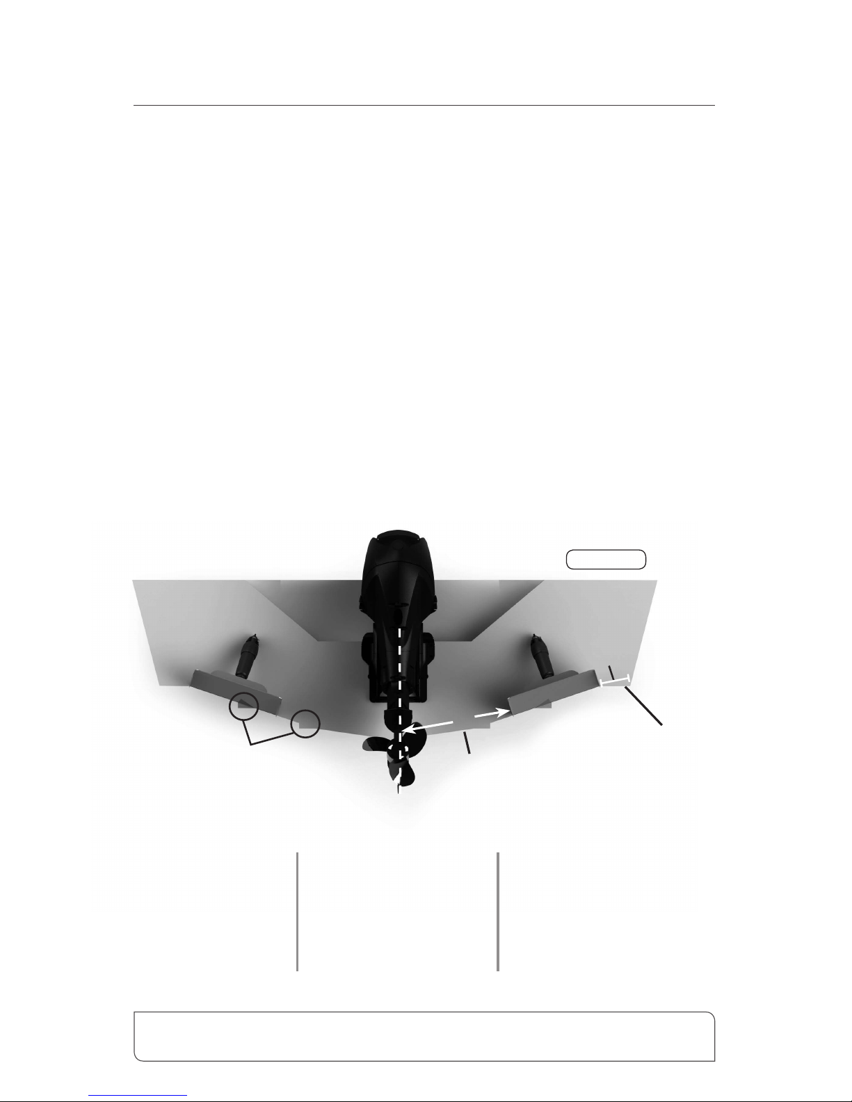
Standard “V” Hull Installation
(At least 8" from
centerline of drive)
8"
3"- 4"
Tabs can be mounted
over strakes if necessary
• Electric drill
• 5/32", 9/16", 7/64"
& 3/16" drill bits
• Tape measure
• Phillips screwdriver
• Marine epoxy
• Straight edge
• Marking pencil
• 4' (1.22 m) level
• 3M 5200 sealant
or equivalent
• 2.5" (6.35 cm) or
1" (2.54 cm) hole saw
(See pg. 28 & 29)
Tools and Materials List
Chine
Figure 1
Bennett Marine | Bolt Electric Trim Tab System
11
continued Actuator & Tab Installation
Installing the Trim Tabs
If your set came with adjustable upper hinge actuators (BEA3000), follow the
“Installing the Trim Tabs” instructions in this section, until instructed to skip ahead.
Position the tab: Using the backing plate, choose a location 3-4" from the chine
(see gure 1 on page 10). Maintain a minimum of 8" from the centerline of your
drive unit to the closest edge of the trim tab. Align the bottom of the backing plate
as per gure 2. e hole pattern on the backing plate should be closer to the
bottom edge of the backing plate.
• Mark the pilot holes using the backing plate as a template. Make sure the tabs
can be mounted in the same location on both sides.
Verify that there are no mounting restrictions inside or outside the transom.
• Drill the mounting plate holes, using a 5/32" drill bit.
1/2" for
9" Chord
Mount the
backing plate
1/8" to 1/4" from
the hull bottom
1/8"
Fixed upper hinge is flexible
to accomodate varying transom angles
5/8" for
12" Chord
Straight Edge
Transom
Figure 2
Bennett Marine | Bolt Electric Trim Tab System
12
Actuator & Tab Installation continued
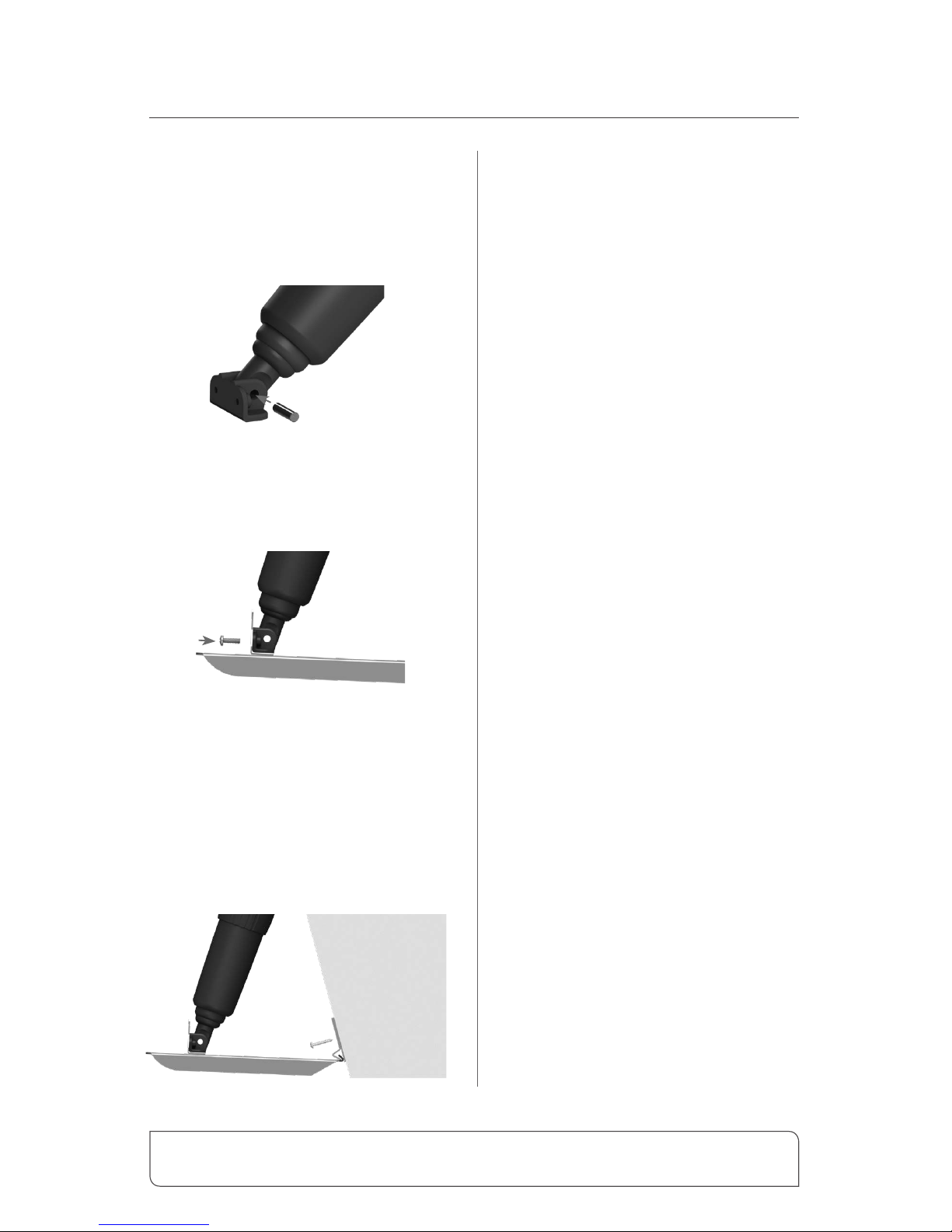
Installing the Actuators
• Install the lower hinge to the
actuator using the supplied
stainless steel pin.
• Attach the actuator to the
Trim Tab: Secure the lower hinge
with the supplied 1/4-20 x 3/4"
Phillips Head machine screws.
• Install Tab and Hinge Assembly:
Coat the threads of the #10 x 1-1/4"
screws in 3M 5200 sealant (or
equivalent) before inserting into the
backing plate pilot holes. Install the
screws in 3/4 of their length. Slide
the trim tab between backing plate
and hinge plate. Tighten the screws.
• Set Final Actuator Position: Use
a straight edge under the trim tab
to make sure the correct negative
angle for your size of tab is achieved
(Refer to Figure 2 on page 11)
is is important to ensure correct
actuator placement (1/2" negative
angle for 9" chord; 5/8" negative
angle for 12" chord; 1" negative
angle for 16" chord).
• Fold wires down, placing the
actuator template (Pg. 30-31)
under the actuator. Align the
outside of the template with the
perimiter of the upper hinge. Tape
the template in place.
• Mark Actuator Position on the
Transom: Using the installation
drilling templates on page 30-31,
mark the three upper hinge hole
centers and the center hole on the
transom.
• Drill Actuator Holes: Using the
drilling templates on page 30-31,
drill the center hole, and three
mounting holes. Be sure to verify
whether your actuators have xed
or adjustable upper hinges as center
hole sizes are dierent for each.
• Repeat the previous steps for the
opposite side of the boat.
If your Bolt set came with adjustable
upper hinge actuators (BEA3000), please
skip to page 14 “Mounting Adjustable
Upper Hinge Actuators (BEA3000) to the
Transom.”
 Loading...