

Page 1
Bennett Pump Company
Commercial and Retail Dispensers
3700/3800 Series Spec. 100 (2nd Generation)
Electronic Commercial & Retail Installation Manual
Only Trained Personnel May Work on This Equipment
Includes Instructions For:
All 3700 Electronic Commercial Dispensers
All 3800 Electronic Retail Dispensers
Remote Dispensers
and
Self-Contained Pumps
READ THIS MANUAL
This manual has important information for safe installation and
operation of this equipment. Read and understand this manual
before applying power. Keep this manual and tell all service
personnel to read this. If instructions are not followed then
bodily injury, death or damage to the equipment may occur.
For new manuals, FAX to:
BENNETT MARKETING
SERVICES
(231)799-6202
or visit our web page at:
http://www.bennettpump.com
Bennett 1218 E. Pontaluna Road, Spring Lake, MI 49456
USA 800-235-7618 Outside USA 231-798-1310 [email protected]
120001 Rev K 1-19-18
www.bennettpump.com
Page 2

Table of Contents
Safety Instructions ................................................................................................ ........................................................................ 3
Introduction for the 3000 Series Electronic Commercial and Retail Dispensers ................................................................... 4
Determining the Model Number .................................................................................................................................................... 8
Product Specifications .................................................................................................................................................................. 9
Dispenser Identification Number Summary (DIN) ......................................................................................................................... 10
Unloading, Unpacking and Inspecting a New Dispenser ............................................................................................................... 12
Lifting a New Dispenser and Placing it on the Island .................................................................................................................... 13
Alternative Method for Lifting the Dispenser - High Hose .............................................................................................................. 14
Anchoring the Dispenser to the Island .......................................................................................................................................... 14
Determining the Number of Product Supply Pipes Needed ........................................................................................................... 15
Mechanical and Plumbing Notes .................................................................................................................................................. 15
Pipe Lines and Under Ground Containment Sumps ..................................................................................................................... 16
Above Ground Tank Installation with Self Contained Pumps ........................................................................................................ 17
Electrical Field Wiring - General Information ................................................................................................................................ . 18
Purging Product Lines for Remote Dispensers ............................................................................................................................. 20
Purging Product Lines for Self Contained Systems ....................................................................................................................... 20
Piping Notes for Self Contained Systems ..................................................................................................................................... 21
Wiring the 3700 Series Dispenser (Commercial) ...................................................................................................................... 22
Determine the Number of Wires Needed .............................................................................................................................. 23
Pulling the Field Wires .......................................................................................................................................................... 25
Installing the Wire Separator ................................................................................................................................................ 25
Proper Equipment Grounding ............................................................................................................................................... 25
AC Power Installation ........................................................................................................................................................... 26
Connecting Pump Motor Power for Remote Dispensers ....................................................................................................... 26
Installing RC Networks ......................................................................................................................................................... 27
Connecting Suction Pump Motor Power for Suction Pump Systems ..................................................................................... 27
Connecting the Communication Wiring ................................................................................................................................. 28
Connecting Field Wiring to the Mechanical Interface Board .................................................................................................. 29
Pulse Output Field Wiring Table ........................................................................................................................................... 30
Setting the Jumpers on the Pulse Output Board ................................................................................................................... 31
CPU Board Jumper Configuration ........................................................................................................................................ 32
CPU Board Jumper Configuration - Diagram ........................................................................................................................ 33
Dispenser Startup and Checklist................................................................................................................................................... 35
Potting Instructions ....................................................................................................................................................................... 37
How to Mechanically Calibrate the SB-100 Meter (M-Cal Option) ................................................................................................. 38
How to Electronically Calibrate the SB-100 Meter (E-Cal)............................................................................................................. 39
Wiring the 3800 Series Dispenser (Retail) ................................................................................................................................ 41
Determining the Number of Wires Needed ........................................................................................................................... 42
Pulling the Field Wires .......................................................................................................................................................... 44
Installing the Wire Separator ................................................................................................................................................ 44
Proper Equipment Grounding ............................................................................................................................................... 44
AC Power Installation ........................................................................................................................................................... 45
Connecting Pump Motor Power for Remote Dispensers ....................................................................................................... 45
Installing RC Networks ......................................................................................................................................................... 46
Connecting Suction Pump Motor Power for Suction Pump Systems ..................................................................................... 46
Connecting Communication Wiring ....................................................................................................................................... 47
Connecting Field Wires to the Mechanical Interface Board ................................................................................................... 48
Pulse Output Field Wiring Table ........................................................................................................................................... 49
Setting the Jumpers on the Pulse Output Board ................................................................................................................... 50
Dispenser Startup and Checklist................................................................................................................................................... 51
Potting Instructions ....................................................................................................................................................................... 53
How to Mechanically Calibrate the SB-100 Meter (M-Cal Option) ................................................................................................. 54
How to Electronically Calibrate the SB-100 Meter (E-Cal)............................................................................................................. 55
Footprint Dimensions and Wiring Diagrams ............................................................................................................................ 57
Audit Form ................................................................................................................................................................................... 83
PCI SSC - Legal Terms and Conditions ........................................................................................................................................ 85
Bennett Limited Warranty for Products Installed in the United States - 3000 Retail & Commercial ................................................ 86
Bennett International Limited Warranty for Dispensers and Pumps .............................................................................................. 87
Not all equipment covered in this manual is listed by Underwriters Laboratories. Only those
products that bear the Listing Mark of Underwriters Laboratories are listed.
Examine the shipment immediately upon arrival to make certain there has been no damage or loss in
transit. Bennett Pump Company, as shipper, is not liable for the hazards of transportation. Please
make damage claims directly to the truck line.
NOTICE
IMPORTANT
2
120001 Rev K 1-19-18
Page 3
Safety Instructions
WARNING ADVERTISSEMENT ADVERTENCIA
For the safe installation of this equipment, read and understand all warning and cautions. Look for these
warnings:
“DANGER” means: If you do not follow the instruction s, severe injury or death will occur.
“WARNING” means: If you do not follow the instructions, severe injury o r d eath can o c cur.
“CAUTION” means: If you do not f ollow t he instructions, damage can occu r to the
equipment.
DANGER: Fir e, explosion, injury or
death will occur if fuel filters are changed by
untrained personnel. Make sure only trained
personnel change filters.
DANGER: To prevent i njury to you f rom
vehicles and onlookers, always place a barrier
around this equipment before performing service
or maintenance.
DANGER: Gasoline is flammable.
NO SMOKING OR OPEN FLAME.
DANGER: Discon nect all power to this
equipment and associated submerged pump(s)
during installation, service or any maintenance,
i.e., changing filters.
WARNING: You must have training in the
installation, service or maintenance of this
equipment (dispenser, pump, console, control
box or submerged pump) before working on it.
Maintenance repairs must be done by
authorized personnel only. Warranty work may
only be performed by Bennett certified
technicians.
WARNING: To prev ent electric shock,
keep the electrical parts of the dispenser dry.
WARNING: Electron ic components are
static sensitive. Use proper static precautions
(static straps) before working on the equipment.
WARNING: The emergency shut-off valve
(also called the fire valve, shear valve or impact
valve) must be closed when service or
maintenance is performed on this equipment.
WARNING: You must have training in the
operation and programming of this dispenser
before using it. READ THE OPERATORS
MANUAL.
WARNING: Make su r e t his equipment is
correctly grounded. Failure to do will cause
injury or damage equipment or improper
operation. Improper grounding voids the
warranty.
WARNING: When anchoring the
dispenser, always level the dispenser with shims
before bolting to the island. DO NOT shim just
the middle of the dispenser and bolt down.
CAUTION: Do n ot drill holes in fuel
dispensers. Holes can cause failure of the
electronic equipment. The warranty will become
void. Use only adhesive backed sign mounting
brackets.
IMPORTANT: All trained and licensed technicians must work in accordance to all requirements,
standards, and guidelines specified by the suppliers Environmental Standards® Health, Safety,
Security & Environment (HSSE) policies. Note: Bennett Pump highly recommends all technicians
observe HSSE policies defined by the supplier. Bennett Pump does not impose any restrictions or
additional requirements contained in Environmental Standards® Health, Safety, Security & Envi-
ronment (HSSE) policies.
READ AND UNDERSTAND ALL WARNING LABELS ATTACHED TO THE DISPENSER
3
120001 Rev K 1-19-18
Page 4
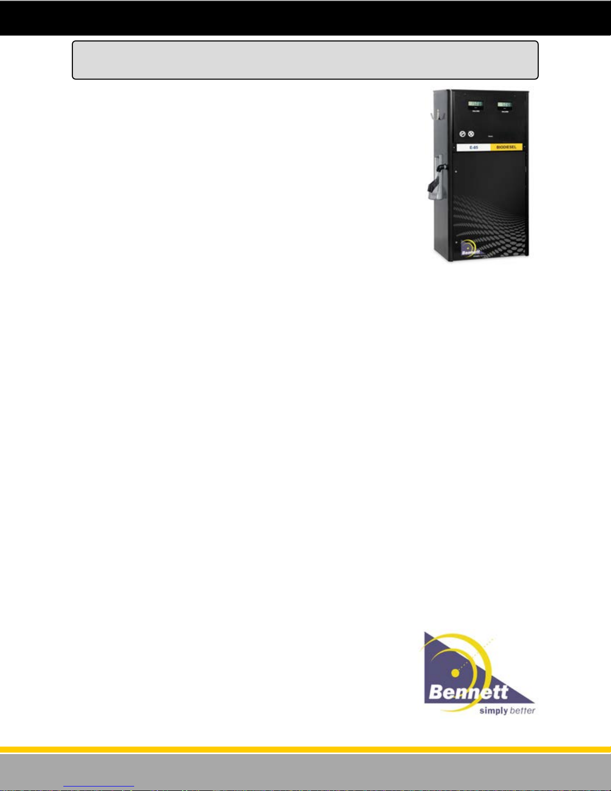
Electronic 3000 Series SPEC. 100
Commercial Series Models (Volume Only) - Standard Flow
Standard Features
Simplified electronic computer.
Stand-alone or Interfaced to Control Device.
RS485 interface.
Exclusive eCal
Magnet activated electronic totals display.
Programmable unit of measure for US
gallons, liters, or imperial gallons.
Operates from 115/230Vac, 60/50Hz, or 380
Vac, 50Hz.
Suction pump models feature 1-HP
continuous duty motor(s).
Back lighted 1-inch LCD displays.
Satellite Outlet Connection for remotes
Singles, 1-Product Twins, or 2-Product
Twins.
Construction
Low Hose Cabinet Design.
High Hose Cabinet Design.
Front or side mount nozzle boots.
Long-life cabinet using galvanneal
components and powder coated panels.
Black end panels & top.
Black electronics door - hinged, swing down.
Red lower doors (optional colors available) -
hinged, swing out.
Heavy duty hose hook (optional internal hose
retractor available for low hose models).
Computer
Simplified. single board design electronics.
Includes CPU, power supply, display, eCal,
RS485 connection, electromechanical analog
totalizer, push-button programming switches,
wiring terminal strip.
LED Backlighting board for the LCD display.
Optical pulser.
Designed for temperature extremes—no
heaters or cooling fans required.
Long life, highly visible back lighted LCD
display, 1” (2.54cm) numerals.
Battery Backup for last sale recall during
power outage (required for resale of fuel).
Simple 2-command protocol via RS485
interface to fleet management systems
supplies pump status, pulses, volume sale &
volume totals.
Field wiring goes directly to terminal strip on
Computer (for new installations pull 72” of
wire above grade level).
Transaction display of: 999.999 for gallons,
9999.99 for liters.
Electronic hose totals of:
Electromechanical totalizer 9999999
Built-in diagnostics with error codes.
TM
(Electronic Calibration).
99999999.999 for gallons (8.3).
999999999.99 for liters (9.2).
Hydraulics
Precision Bennett SB100 Meter, 4-piston,
positive displacement design.
Type 75 or type 75-HD Bennett sliding vane
pumping unit with integral vortex air
eliminator.
SB100 meter is electronically calibrated
(eCal). Mechanically calibrated meter is
optional.
All remote units include built-in inlet check
valves to keep the hydraulics full and prevent
meter/pulser count-up when the submersible
pump pressurizes the system.
Remote units use replaceable paper filter
cartridge.
Suction pumps use a reusable strainer.
All units feature 1” hose outlets
Suction units include 1-1/2” ground joint
union and riser pipe. Union & riser pipe not
supplied for remote units.
Options
E85 alcohol blend compatibility option.
Programmable dual channel, dual hose
Pulse Output Board to interface to fleet
management systems & tank monitoring
system if RS485 is not used.
2-Stage prepay/preset electric solenoid valve
for 1-product, 1-hose or 2-product, 2-hose
suction pumps. (valve is standard on all other
models).
Internal spin-on filter & adapter for remote
models.
For high hose models: balance vapor coax
hose outlet & internal vapor return piping.
Sub pump relay 3-phase contactor.
Intercom speaker for high hose models.
Stainless steel lower doors and/or end
panels.
Stainless “All Panels” Option (lower doors,
end panels, cover for electronics
compartment).
“Super Stainless” Option is “All Panels”
option plus electronics door and grade panel
holder.
Custom lower door colors and/or graphics.
Mechanical calibration dial for SB100 meter.
Hose clamp for 5/8”, 3/4”, or 1” I.D. hose.
Explosion proof junction box for lower
hydraulic area.
380 Volt 3-Phase Motors.
Pressure regulating valve for suction pumps
with aboveground tank installation.
Internal hose retractor (low hose models).
Strainer in lieu of filter w/ or w/o cloth sack.
Hoses, nozzles, swivels.
Companion Satellites (GoPump style in low
or high hose cabinets or economy LPS style).
Satellite pipe kit installed in remote master.
Bennett dispensers may dispense
“Av-Gas”, but cannot dispense Jet
Fuel to fuel jet aircraft.
For information on flow rates and
model configurations see our
Price Lists.
TM
UL
listed.
Certified for resale applications. The
N.T.E.P. Certificate of Conformance
is available upon request.
Units have been tested and found
to comply with the limits for a Class
A computing device in accordance
with Subpart J of Part 15 of FCC
Rules regarding radio frequency
interference.
Specifications in this document are
subject to change without notice.
4
120001 Rev K 1-19-18
Page 5
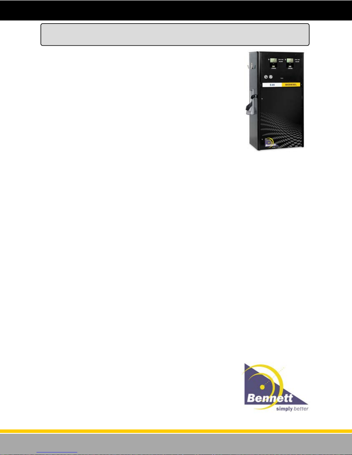
Electronic 3000 Series SPEC. 100
Retail Series Models (Money & Volume) - Standard Flow
Standard Features
Simplified electronic computer.
Stand-alone or Interfaced to Control Device.
RS485 interface or current loop or dual pulse
output (i.e. 4-pulse output channels).
Exclusive eCal
Magnet activated electronic totals display.
Programmable unit of measure for US
gallons, liters, or imperial gallons.
Operates from 115/230Vac, 60/50Hz, or 380
Vac, 50Hz.
Suction pump models feature 1-HP
continuous duty motor(s).
Back lighted 1-inch LCD displays.
Satellite Outlet Connection for remotes
Singles, 1-Product Twins, 2-Product Twins.
Construction
Low Hose Cabinet Design.
High Hose Cabinet Design.
Front or side mount nozzle boots.
Long-life cabinet using galvanneal
components and powder coated panels.
Black end panels & top.
Black electronics door - hinged, swing down.
Optional color lower doors - hinged, swing
out.
Heavy duty hose hook (optional internal hose
retractor available for low hose models).
Computer
Simplified single board design electronics.
Includes CPU, power, display, eCal, RS485
or current loop connection, electromechanical
analog totalizer, push-button programming
switches, wiring terminal strip.
LED Backlighting board for the LCD display.
Optical pulser.
Designed for temperature extremes—no
heaters or cooling fans required.
Long life, highly visible back lit LCD display,
1” (2.54cm) numerals for money & volume;
1/2” (1.27cm) numerals for price-per-volume.
Battery Backup for last sale recall during
power outage (required for resale of fuel).
Simple 2-command protocol via RS485
interface to fleet management systems
supplies pump status, pulses, volume sale &
volume totals.
Current loop Bennett fuel protocol interface.
Field wiring goes directly to terminal strip on
Computer (for new installations pull 72” of
wire above grade level).
Built-in diagnostics with error codes.
Transaction display of: 999.999 for gallons,
9999.99 for liters and 6-digits for money with
programmable decimal point.
Electronic hose totals of:
Electromechanical totalizer 9999999.
TM
(Electronic Calibration).
99999999.999 for gallons (8.3)
999999999.99 for liters (9.2)
Hydraulics
Precision Bennett SB100 Meter, 4-piston,
positive displacement design.
Type 75 or type 75-HD Bennett sliding vane
pumping unit with integral vortex air
eliminator.
SB100 meter is electronically calibrated
(eCal). Mechanically calibrated meter is
optional.
All remote units include built-in inlet check
valves to keep the hydraulics full and prevent
meter/pulser count-up when the submersible
pump pressurizes the system.
Remote units use replaceable paper filter.
Suction pumps use a reusable strainer.
All units feature 1” hose outlets; .
Suction units include 1-1/2” ground joint
union and riser pipe. Union & riser pipe not
supplied for remote units.
Options
Debit/Credit card reader (single display per
side models only).
E85 alcohol blend compatibility option.
Programmable Dual Pulse Output Board to
interface to fleet management systems &
tank monitoring system if RS485 is not used.
2-Stage prepay/preset electric solenoid valve
for 1-product, 1-hose or 2-product, 2-hose
suction pumps. (valve is standard on all other
models).
Internal spin-on filter & adapter for remote
models.
For high hose models: balance vapor coax
hose outlet & internal vapor return piping.
Sub pump relay 3-phase contactor.
Intercom speaker for high hose models.
Stainless steel lower doors and/or end
panels.
Stainless “All Panels” Option (lower doors,
end panels, cover for electronics
compartment.
“Super Stainless” Option is “All Panels”
option plus electronics door and grade panel
holder).
Custom lower door colors and/or graphics.
Mechanical calibration dial for SB100 meter.
Hose clamp for 5/8”, 3/4”, or 1” I.D. hose.
Explosion proof junction box for lower
hydraulic area.
380 Volt 3-Phase Motors.
Local Preset (attendant preset)
Pressure regulating valve for suction pumps
with aboveground tank installation.
Internal hose retractor.
Strainer in lieu of filter w/ or w/o cloth sack.
Hoses, nozzles, swivels.
Companion Satellites (GoPump style in low
or high hose cabinets or economy LPS style).
Satellite pipe kit installed in remote master.
Satellite in use light for remote master.
Bennett dispensers may dispense
“Av-Gas”, but cannot dispense Jet
Fuel to fuel jet aircraft.
For information on flow rates and
model configurations see our
Price Lists.
TM
UL
listed.
Certified for resale applications. The
N.T.E.P. Certificate of Conformance
is available upon request.
Units have been tested and found
to comply with the limits for a Class
A computing device in accordance
with Subpart J of Part 15 of FCC
Rules regarding radio frequency
interference.
Specifications in this document are
subject to change without notice.
5
120001 Rev K 1-19-18
Page 6
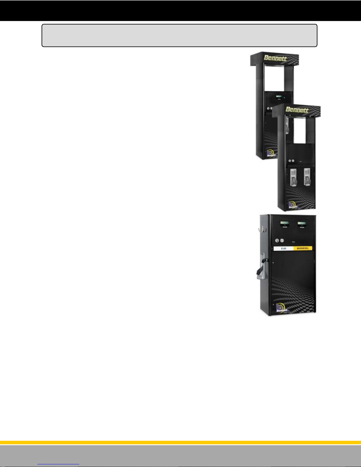
Electronic 3000 Series SPEC. 100
Commercial Big Fueler Series Models (Volume Only) - High Flow
Standard Features
Simplified electronic computer.
Stand-alone or Interfaced to Control Device.
RS485 interface.
Exclusive eCal
Magnet activated electronic totals display.
Programmable unit of measure for US
gallons, liters, or imperial gallons.
Operates from 115/230Vac, 60/50Hz, or 380
Vac, 50Hz.
Back lighted LCD displays.
Satellite Outlet Connection.
Remote dispensers only.
Single Master, dual master, master/satellite
combination, & master-master/satellitesatellite dual combination.
Field configurable for single point or
simultaneous master & satellite fueling.
Construction
Low Hose Cabinet Design.
High Hose Cabinet Design
Front or side mount nozzle boots.
Heavy duty lift-to-start nozzle boots
accommodate high speed truck stop nozzles.
Long-life cabinet construction using
galvanneal components and powder coated
panels.
Black end panels & top.
Black electronics door - hinged, swing down.
Green lower doors (optional colors available)
- hinged, swing out.
Heavy duty hose hook for low hose models.
Computer
Simplified single board design electronics.
Includes CPU, power supply, display, eCal,
RS485 connection, electromechanical analog
totalizer, push-button programming switches,
wiring terminal strip.
LED Backlighting board for the LCD display.
Magnetic drive, tamper-proof pulser.
Designed for temperature extremes—no
heaters or cooling fans required.
Long life, highly visible back lighted LCD
display, 1” (2.54cm) numerals.
Battery Backup for last sale recall during
power outage (required for resale of fuel).
Simple 2-command protocol via RS485
interface to fleet management systems
supplies pump status, pulses, volume sale
and volume totals.
Field wiring goes directly to terminal strip on
Computer (for new installations pull 72” of
wire above grade level).
Computer (cont’d)
Transaction display of: 999.999 for gallons,
9999.99 for liters.
Electronic hose totals of:
Electromechanical totalizer 9999999.
Built-in diagnostics with error codes.
TM
(Electronic Calibration).
99999999.999 for gallons (8.3)
999999999.99 for liters (9.2)
Hydraulics
Rotary meter rated at 70gpm maximum.
Built-in inlet check valves to keep the
hydraulics full and prevent meter/pulser count
-up when the submersible pump pressurizes
the system.
1-1/2” 2-Stage prepay/preset electric
solenoid valve.
Dual spin-on filters
1-1/4” elbow hose outlet(s) with 1-1/4” x 1”
reducer bushing.
Note: Union & riser pipe not supplied for
remote units.
Self-Contained unit available (up to 40gph)
Options
Programmable dual channel, dual hose
Pulse Output Board to interface to fleet
management systems & tank monitoring
system if RS485 is not used.
Sub pump relay 3-phase contactor.
Intercom speaker for high hose models.
Explosion proof junction box for lower
hydraulic area.
Stainless steel lower doors and/or end
panels.
Stainless “All Panels” Option (lower doors,
end panels, cover for electronics
compartment).
“Super Stainless” Option is “All Panels”
option plus electronics door and grade panel
holder.
Custom lower door colors and/or graphics.
Hoses, nozzles, swivels.
Satellite-in-use light(s) for remote master.
Satellite pipe kit installed in remote master.
Companion Satellites (Full size Big Fueler
styling in low or high hose models. Singles
or Duals, One or two sided. Note: a dual
can be one or two sided.).
Companion Satellites (LPS Economy low
hose models in single or dual style. Note:
Duals are two sided only.).
For further details about satellite models, see
our Product Cut Sheet for Satellites.
Bennett dispensers may dispense
“Av-Gas”, but cannot dispense Jet
Fuel to fuel jet aircraft.
For information on flow rates and
model configurations see our
Price Lists.
TM
UL
listed.
Certified for resale applications. The
N.T.E.P. Certificate of Conformance
is available upon request.
6
Units have been tested and found
to comply with the limits for a Class
A computing device in accordance
with Subpart J of Part 15 of FCC
Rules regarding radio frequency
Specifications in this document are
subject to change without notice.
120001 Rev K 1-19-18
Page 7
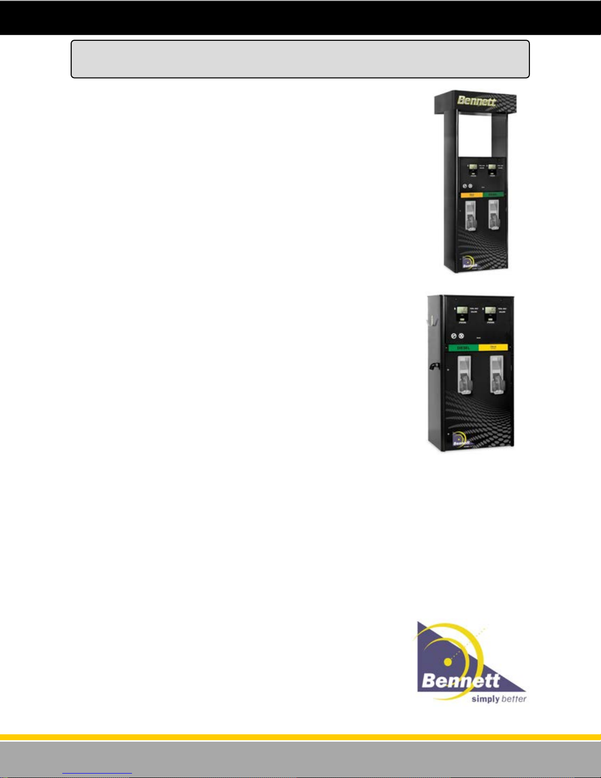
Electronic 3000 Series SPEC. 100
Retail Big Fueler Series Models (Money & Volume) - High Flow
Standard Features
Simplified electronic computer.
Stand-alone or Interfaced to Control Device
(e.g. Trendar, VeriFone).
RS485 interface or current loop or dual pulse
output (i.e. 4-pulse output channels).
Exclusive eCal
Magnet activated electronic totals display.
Programmable unit of measure for US
gallons, liters, or imperial gallons.
Operates from 115/230Vac, 60/50Hz, or 380
Vac, 50Hz.
Back lighted 1-inch LCD displays.
Satellite Outlet Connection.
Single Master, dual master, master/satellite
combination, & master-master/satellitesatellite dual combination.
Field configurable for single point or
simultaneous master & satellite fueling.
Construction
Low Hose Cabinet Design.
High Hose Cabinet Design.
Front or side mount nozzle boots.
Heavy duty lift-to-start nozzle boots
accommodate high speed truck stop nozzles.
Long-life cabinet using galvanneal
components and powder coated panels.
Black end panels & top.
Black electronics door - hinged, swing down.
Optional color lower doors - hinged, swing
out.
Heavy duty hose hook for low hose models.
Computer
Simplified single board design electronics.
Includes CPU, power, display, eCal, RS485
or current loop connection, electromechanical
analog totalizer, push-button programming
switches, wiring terminal strip.
LED Backlighting board for the LCD display.
Magnetic drive, tamper-proof pulser.
Designed for temperature extremes—no
heaters or cooling fans required.
Long life, highly visible back lit LCD display,
1” (2.54cm) numerals for money & volume;
1/2” (1.27cm) numerals for price-per-volume.
Battery Backup for last sale recall during
power outage (required for resale of fuel).
Simple 2-command protocol via RS485
interface to fleet management systems
supplies pump status, pulses, volume sale &
volume totals.
Current loop Bennett fuel protocol interface.
Field wiring goes directly to terminal strip on
Computer (for new installations pull 72” of
wire above grade level).
Built-in diagnostics with error codes.
TM
(Electronic Calibration).
Computer (cont’d)
Transaction display of: 999.999 for gallons,
9999.99 for liters and 6-digits for money with
programmable decimal point.
Electronic hose totals of:
99999999.999 for gallons (8.3)
999999999.99 for liters (9.2)
Electromechanical totalizer 9999999.
Hydraulics
Rotary meter rated at 70gpm maximum.
Built-in inlet check valves to keep the
hydraulics full and prevent meter/pulser count
-up when the submersible pump pressurizes
the system.
1-1/2” 2-Stage prepay/preset electric
solenoid valve.
Dual spin-on filters
1-1/4” elbow hose outlet(s) with 1-1/4” x 1”
reducer bushing.
Note: Union & riser pipe not supplied for
remote units.
Self-Contained unit available (up to 40gph)
Options
Local Preset (Attendant Preset)
Debit/Credit card reader (single display per
side models only).
Programmable Dual Pulse Output Board to
interface to fleet management systems &
tank monitoring system if RS485 is not used.
Sub pump relay 3-phase contactor.
Intercom speaker for high hose models.
Explosion-proof junction box for lower
hydraulic area.
Stainless steel lower doors and/or end
panels.
Stainless “All Panels” Option (lower doors,
end panels, cover for electronics
compartment.
“Super Stainless” Option is “All Panels”
option plus electronics door and grade panel
holder).
Custom lower door colors and/or graphics.
Hoses, nozzles, swivels.
Satellite-in-use light(s) for remote master.
Satellite pipe kit installed in remote master.
Companion Satellites (Full size Big Fueler
styling in low or high hose models. Singles
or duals, one or two sided. Note: a dual can
be one or two sided).
Companion Satellites (LPS Economy low
hose models in single or dual style. Note:
duals are two sided only).
For further details about satellite models, see
our Product Cut Sheet for Satellites.
For information on flow rates and model
configurations see our Price Lists.
Certified for resale applications. The
N.T.E.P. Certificate of Conformance
is available upon request.
Units have been tested and found
to comply with the limits for a Class
A computing device in accordance
with Subpart J of Part 15 of FCC
Rules regarding radio frequency
interference.
Specifications in this document are
subject to change without notice.
7
120001 Rev K 1-19-18
Page 8

Determining the Model Number
Determine the model number of the dispenser from the serial plate located on the dispenser. Utilizing
the chart below determine the features of the dispenser to be installed. Understanding the features of
the dispenser to be installed will be helpful in understanding the proper installation of the dispenser.
How a Model for the 3000 Series Dispensers is Made Up.
Pump Model Retail Commercial Electronics Flow Rate # Products # Hoses
3711
3712
3722
3724
3811
3812
3822
3824
X
X
X
X
X
X
X
X
531 Package All 1 1
531 All 1 2
531 All 2 2
531 All 2 4
210 Package All 1 1
210 All 1 2
210 All 2 2
210 All 2 4
See Note 1
Motor
See Note 2
See Note 2
Note 1 - Flow Rate -
Standard - *23gpm (Remote) , 15 gpm (Self Contained)
Heavy Duty Suction - 24 gpm
Big Fueler Suction - 35 gpm (nominal with one hose active, 40 gpm total with Master and Satellite in
simultaneous flow ) with 1-1/2” valve.
Big Fueler Remote - 35 gpm (nominal with one hose active, 50 gpm total with Master and Satellite in
simultaneous flow) with 1-1/2” valve.
*Flow rates are “nominal” under ideal test conditions without accounting for system restrictions such as
hanging hardware. Actual flow rates will vary depending on conditions of installation.
Note 2 - Motor -The hydraulic arrangement can be as follows-
Remote
(submerged pump)
Standard/Heavy Duty
Suction with (1 Horse Power) Standard 1 phase 115/230 VAC 50/60 Hz
Suction with (1 Horse Power) Standard 1 phase 115/230 VAC 50/60 Hz with prepay valves
Suction with (1 Horse Power) 3 phase 380 VAC 50 Hz
Suction with (1 Horse Power) 3 phase 380 VAC 50 Hz with prepay valves
Big Fueler
Suction with (2 Horse Power) 1 phase 230 VAC 50/60 Hz with prepay valves
Suction with (2 Horse Power) 3 phase 380 VAC 50/60 Hz with prepay valves
8
120001 Rev K 1-19-18
Page 9

Product Specifications
POWER REQUIREMENTS
AC Power Input, Electronic ............................................. Universal Input 85-270 Volts A.C. 50/60 Hz.
DC Power Supply Outputs ............................................. +5VDC 100mA Max, +12 VDC 100mA Max.
DC Power Supply Outputs .............................. +24 VDC 1.0 Amps Max., +5 VDC Isolated 50mA Max
Nickel-Cadmium Battery Output ........................................................... +10.8 VDC, 40 Milliamp Hours
NOTE: Self-Contained dispenser 1-HP motors are set at the factory for 115V. 2-HP motors can only be
used at 230V and are not interchangeable. (Big Fueler Suction Models)
ENVIRONMENTAL REQUIREMENTS
Operating Temperature Range: ....................................................... -40°C to +65°C (-40°F to +149°F)
Humidity: .................................................................................................................. 0-95% condensing
DIMENSIONS
3700/3800 Series Low Hose (height x width x depth) ................................... *60” H x 30” W x 20” D
3700/3800 Series High Hose (height x width x depth) .................................. *88” H x 30” W x 20” D
*Without Valance.
9
120001 Rev K 1-19-18
Page 10
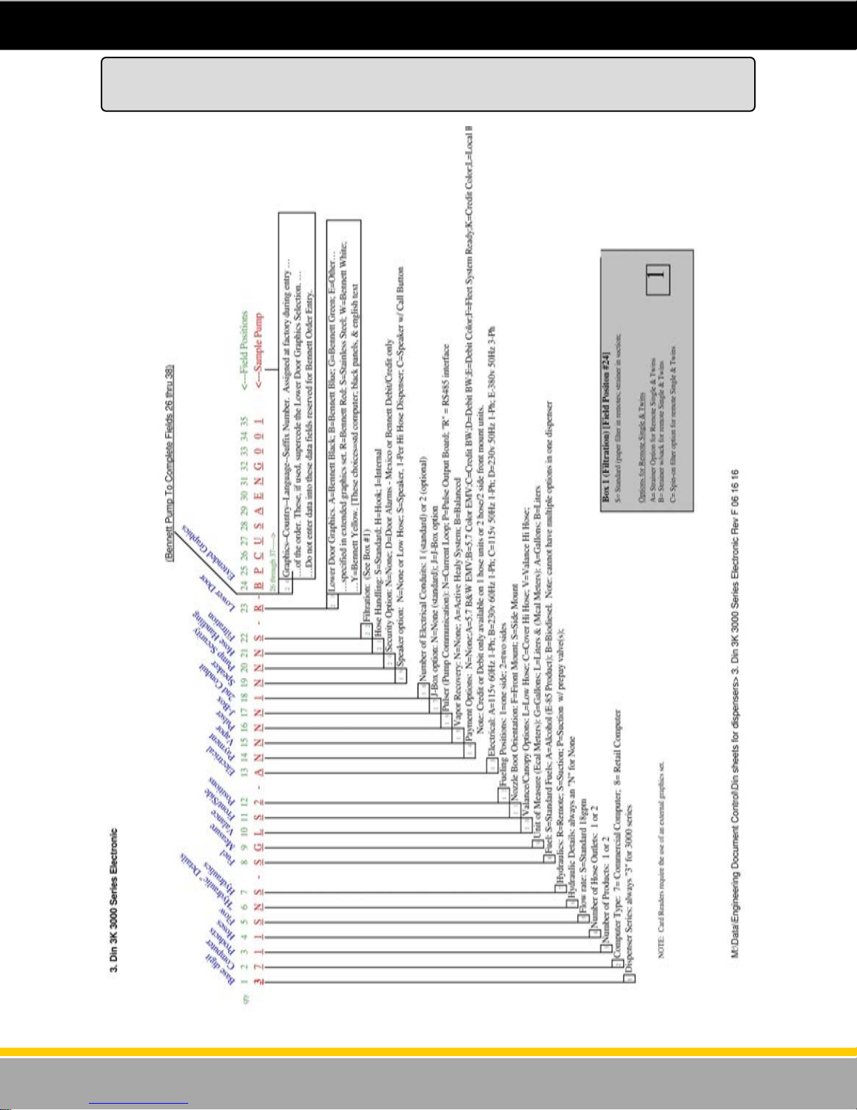
Dispenser Identification Number Summary (DIN)
3000 Electronic - Standard Flow
10
120001 Rev K 1-19-18
Page 11
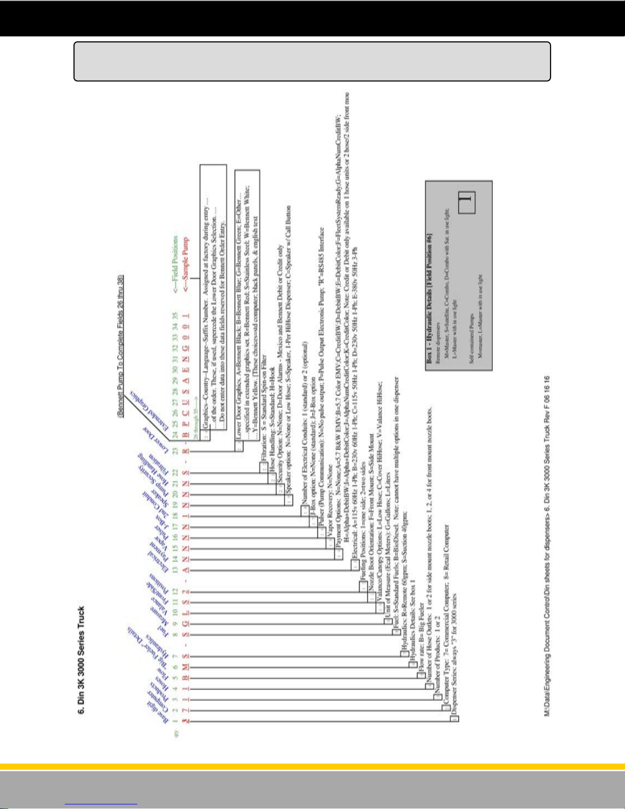
Dispenser Identification Number Summary (DIN)
3000 Electronic - High Flow
11
120001 Rev K 1-19-18
Page 12

Unloading, Unpacking, and Inspecting a New Dispenser
Bennett dispensers are bolted to a pallet and then carefully packaged with cardboard/styrofoam liners
and a cardboard exterior carton. The entire package is then securely wrapped with plastic shrink wrap.
Use a fork lift to lift the dispenser while it is still on the pallet.
Before signing the freight delivery receipt, inspect the carton and pallet for any obvious signs of damage
that may have damaged the dispenser. If any damage is found, instruct the delivery driver to make a
notation on the delivery receipt before signing it. If possible, open the carton and inspect the dispenser
before signing the delivery receipt.
Bennett dispensers are shipped Ex-Works. This means that the title to the equipment passes to the
purchaser at the time the equipment is loaded on the truck at our factory. Freight damage claims are
the responsibility of the purchaser. Bennett will assist in preparing any damage claim, by helping
identify and price any parts necessary to make needed repairs.
Carefully remove the plastic shrink-wrap from the carton. Then carefully remove the cardboard
container and any inside liners. DO NOT DISCARD THE PACKAGING. Should the need arise to
repackage the dispenser, the cardboard packaging can be reused. Plastic shrink-wrap can be
purchased at office supply stores or industrial packaging stores.
Examine the exterior panels for any signs of freight damage. If damage is found after signing for
delivery, call the freight carrier immediately and request an inspection. DO NOT DISCARD THE
PACKAGING; the inspector will want to examine it.
Once you are sure that there is no freight damage to the exterior of the dispenser, use the door key
(wire tied to the nozzle hook) to unlock the lower door. Remove the lower door from both sides of the
dispenser. Visually examine the interior of the dispenser for shipping damage. While the dispenser is
extremely sturdy, a dispenser that has been “dropped” can suffer damage internally even while it
appears normal on the exterior.
Read the model/serial plate of the dispenser and check to confirm that the hydraulic configuration
matches the order specified.
Report any non-shipping related problems to Bennett Customer Service by mail, facsimile, telephone or
e-mail at the locations specified below:
Bennett Pump Company
Customer Service Services
1218 East Pontaluna Road
Spring Lake, MI 49456
Telephone from USA 1-800-423-6638
Telephone from outside USA 231-798-1310, Extension 287 or 269
Facsimile: 231-799-6202
Email: [email protected]
Website: www.bennettpump.com
For new manuals, visit our web page at www.bennettpump.com
12
120001 Rev K 1-19-18
Page 13
Lifting a New Dispenser and Placing it on the Island
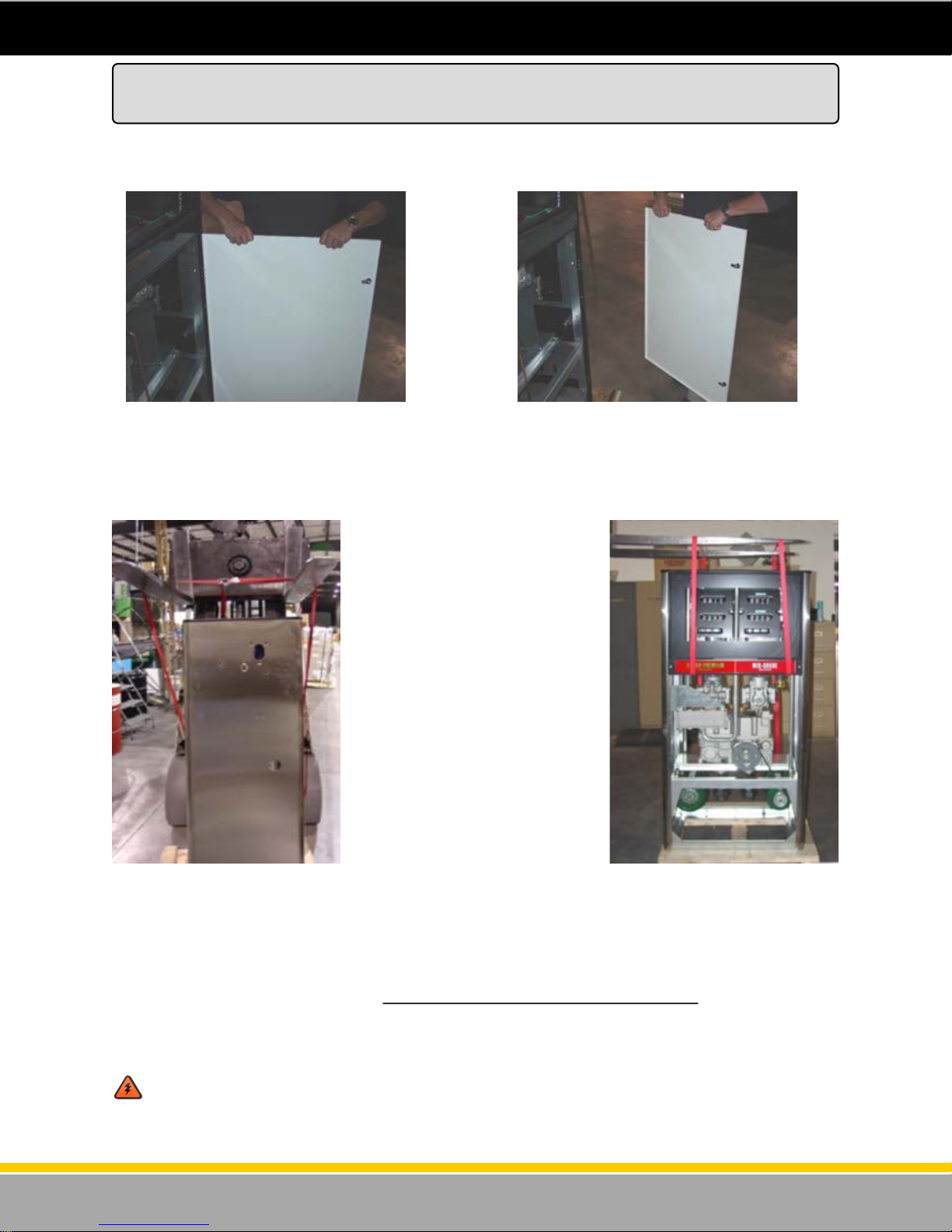
The dispenser is bolted to a pallet with bolts and nuts. With the lower doors removed and safely stored
away, remove the nuts and bolts that secure the dispenser to the pallet as shown in figure 1 and figure
2.
Figure 1 - Unlock the lower door with the keys
that come with the unit. Swing the door open 90
degrees and lift.
Figure 3 - Side View - Using lifting
straps to lift and move the dispenser.
Notice the forks are spread wider than
the pump.
Thread two lifting straps (900 lbs. Capacity each minimum) through the dispenser as shown in figure 3
and figure 4. Be careful not to allow the straps to go under any of the hydraulic castings such as the
meter outlet, copper tubes or valves. The straps should be lifting only against the front and rear chassis.
Use a forklift or pallet lifting device with the forks spread wider than the pump and gently lift the
dispenser. This lifting method will also work on the high hose dispenser. Place the dispenser gently on
the island using care to line up the base anchor bolt holes with the anchor bolts embedded in the
concrete island.
WARNING: Lif t only to t he height required t o set the dispenser on th e island. Keep han ds
and feet clear of the dispenser while it is suspended in the air.
Figure 2 - Remove the door and store in a safe
place until it is ready to be re-installed.
Figure 4 - Front View - Using lifting
straps to lift and move the dispenser.
13
120001 Rev K 1-19-18
Page 14
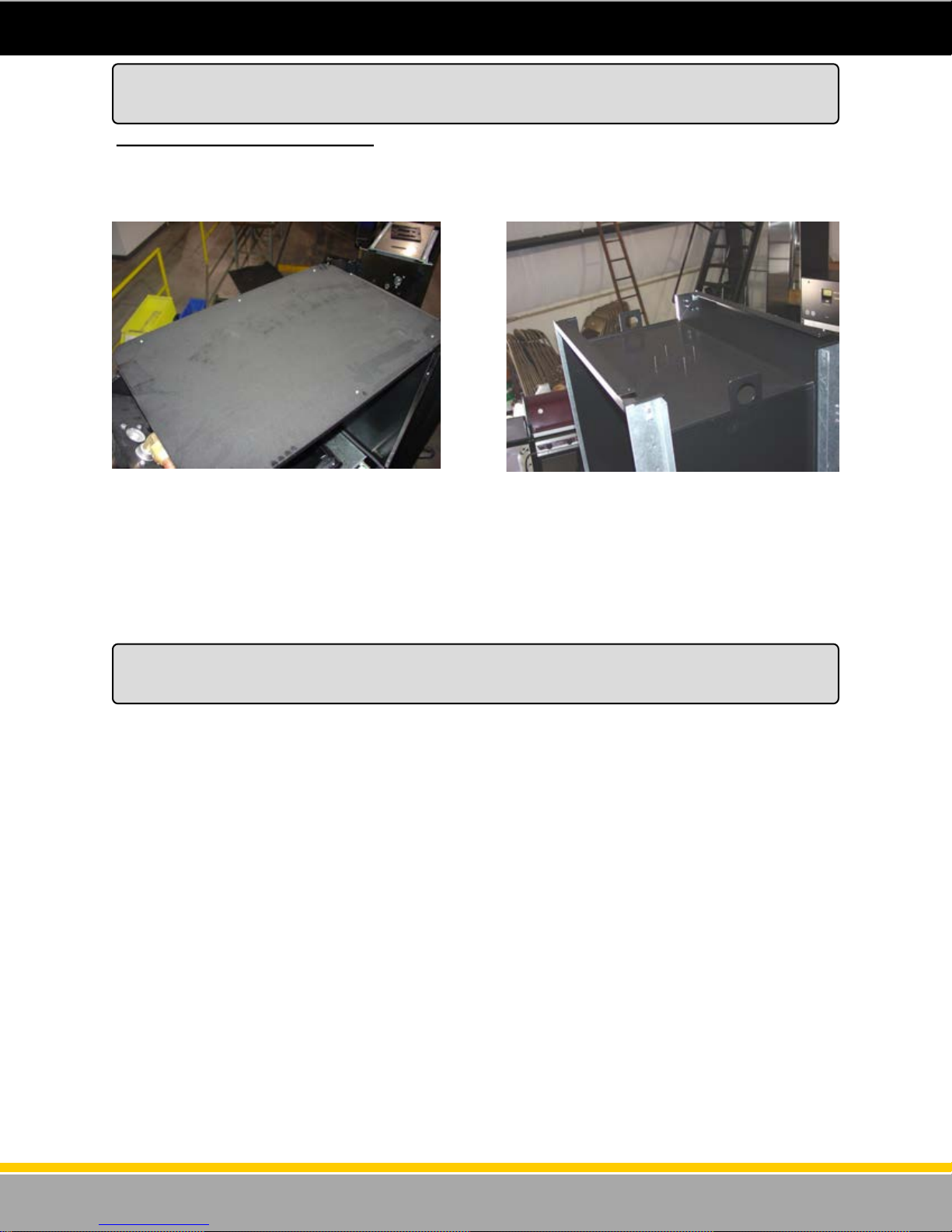
Lifting the Dispenser from Above - On the high hose models, there are lifting brackets provided in the
upper area of the dispenser. There is a cover that has to be removed to access these brackets. (See
figure 5 and figure 6 below).
Lifting a New Dispenser and Placing it on the Island
Alternate Method for High Hose
Figure 5 - Cover is screwed onto the top of the dispenser
and must be removed to access the lifting brackets.
Figure 6 - After the top cover is removed, the lifting brackets can be accessed for lifting the dispenser from above.
Anchoring the Dispenser to the Island
The dispenser must be bolted firmly to the concrete island. The dispenser base is provided with anchor
bolt holes (see base drawings in back of this manual for dimensions). Anchor bolts embedded in the
concrete island must be not less than ½” diameter. The threaded ends of the anchor bolts should
project 1-1/2” above the concrete.
On the Low Hose dispenser, 2 anchor bolts required minimum.
On the High Hose dispenser, 4 anchor bolts required minimum in the outer 4 mounting holes.
Refer to the Footprint Drawings in the back of this manual for hole locations.
When anchoring the dispenser, always level the dispenser with shims before bolting to the island. Place
the shims at the location of the anchor bolts so the dispenser frame is not distorted when the anchor
bolts are tightened down.
14
120001 Rev K 1-19-18
Page 15
Determining the Number of Product Supply Pipes Needed
Step 1: Determi ne the type of suppl y line needed from t he model n umber’s 7t h position on the
serial tag. If the model number is 3711SNR (Note the R) the dispenser will require a submerged pump
and pressurized supply line for each product. If the model number is 3711SNS (Note the S) the pump
will require a suction supply line for each product.
Step 2: Determine the nu m ber of p roduct pipes requ ired by finding the mo d el number below.
Model Number Product Supply Lines Required
3711 / 3811 Use 1 product line plumbed to position 1.
3712 / 3812 Use 1 product line plumbed to position 1.
3722 / 3822 Use 1 product line plumbed to position 1 and 1 product line plumbed to position 2.
*Refer to base drawings in the back of this manual for product inlet locations.
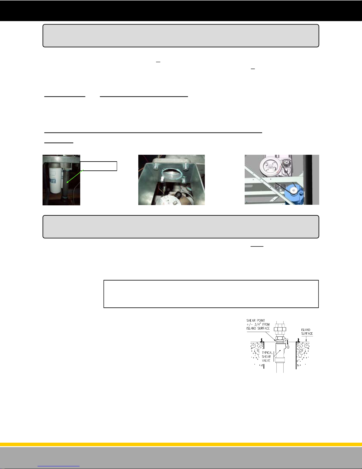
Pipe Size - The 3000 Series do not come with an inlet pipe or joint. The customer is responsible for the
1 1/2” NPT inlet pipe. These will thread directly into the inlet casting (see figure 7, figure 8 and figure 9).
Not Included
Figure 8 - Satellite Figure 7 - Master Big Fueler
Figure 9 - Big Fueler Suction
Mechanical and Plumbing Notes
For remote dispensers, a U.L. Listed Emergency Shut Off Valve is required for each product inlet. The
Emergency Shutoff Valve can be referred to as an “Impact Valve”, “Safety Valve”, “Shear Valve”,
“Crash Valve”, or “Fire Valve”. The Emergency Shut Off Valve must be supported by the island frame or
containment sump frame. Follow all instructions contained in the valve’s installation manual and
observe all national, state, NFPA, and local codes.
For self-contained
(suction) pumps, a
vertical check valve is
required under each
of the pump’s ground
joint unions for the product inlet. The vertical check valve ensures that the
pump’s hydraulic system remains full of product, and it is necessary to
maintain the “prime” of the suction line so that liquid product does not drain
back to the tank. Follow all instructions contained in the vertical check
valve’s installation manual and observe all local codes.
Product inlet locations and dimensions are on the footprint foundation
drawings in this manual.
Listed ground joint union must be installed between sheer section of
Emergency Shut Off valve and dispenser inlet. If rigid product inlet pipes
are used, they must be plumbed so no strain is exerted on the dispenser chassis caused by tightening
down the unions.
For dispensers used with companion satellites, follow all federal, state, and local codes regarding
installation of impact valves.
Install an approved emergency shut off valve, designed to close automatically in the event of severe
impact or fire exposure, in the dispenser supply line at the base of the dispenser. The valve will also
permit safe inspection and maintenance. Follow the installation instructions for the valve being
installed (see figure 10).
Figure 10 - Shear Valve
15
120001 Rev K 1-19-18
Page 16
Pipelines and Underground Containment Sumps
General -
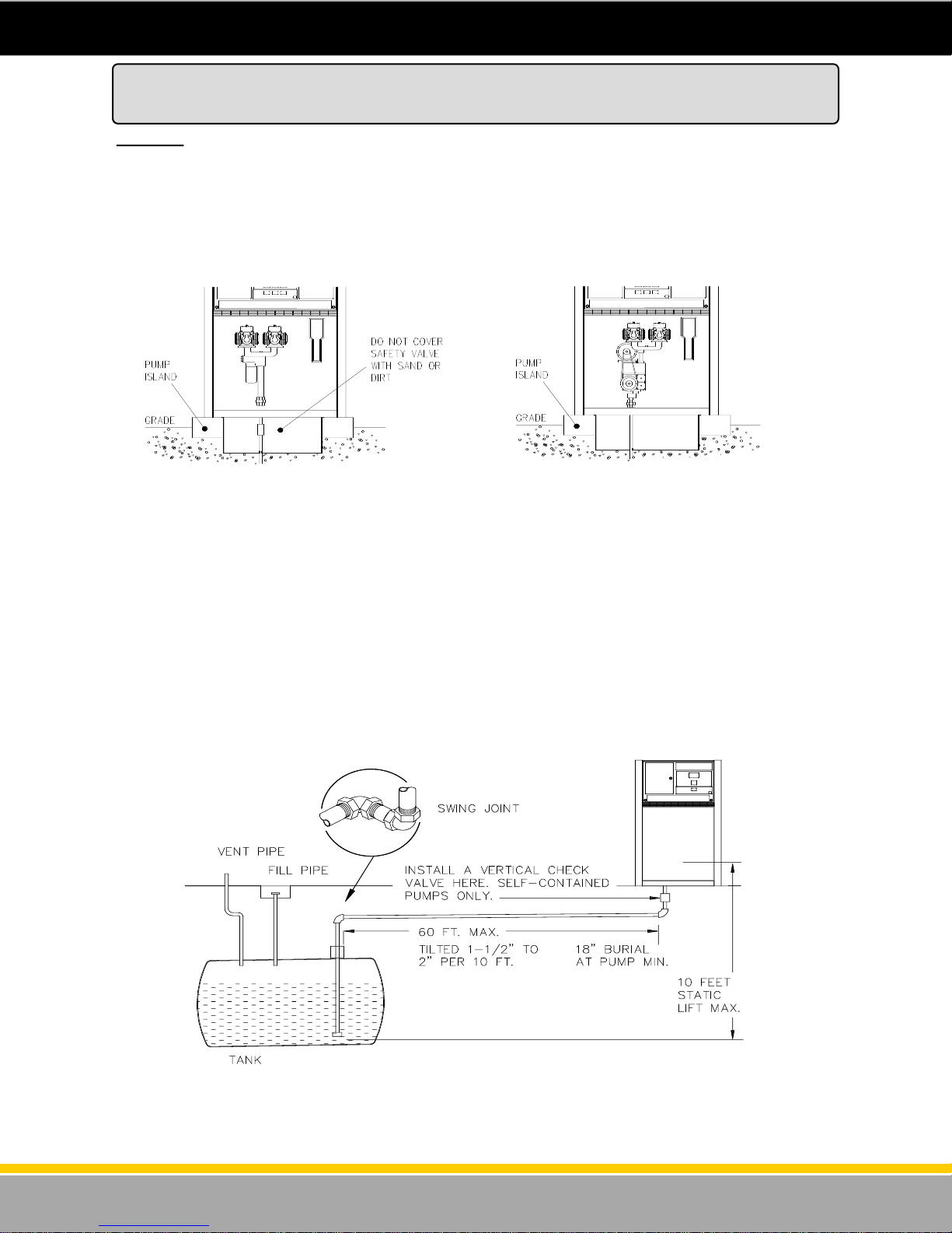
The dispenser must be mounted on a concrete foundation. Do not pour concrete around the product
pipes or electrical conduit. The use of a UL approved containment sump designed for the Bennett
Dispenser Model used is highly recommended. Follow the containment sump manufacture’s installation
instructions for proper installation. If no containment sump is used, fill the sump area with clean sand or
dirt as far up the product pipe as possible once installation is complete. Use water to pack the sand in
place (see figure 11 and figure 12) .
Figure 11 - Example of Remote Figure 12 - Example of Self Contained
NOTE: All piping must be clean of foreign debris, such as: oil, grease and shavings. All
connections must be tight to prevent leaks.
Swing joints or flex pipe must be used at the ends of the horizontal pipe between the dispenser and the
tank (see figure 13). These joints prevent leaks which might develop through ground movement from
settling of the tank, frost heaving of the ground or pump island settling. The joint under the dispenser
also aids proper alignment of the product union or coupling.
NOTE: Please refer to PEI/RP100 Recommended Practices. The installation must conform to
EPA, NFPA, and State regulations for underground storage tanks.
*Acceptance Varies by State*
Figure 13 - Underground Piping
16
120001 Rev K 1-19-18
Page 17

Above Ground Tank Installation with Self Contained Pumps
Bennett self contained dispensers can be used with aboveground tank installations if the following
requirements are met:
An Underwriters (U.L.) Listed Pressure Regulating Valve designed for under-the-pump mounting is
installed for each pumping unit according to the valve manufacturer’s instructions.
Any additional valves suggested by the Pressure Regulating Valve manufacturer are installed
according to the manufacturer’s recommendations.
The installation must be installed and used in accordance with Federal, State, Local, and National
Electrical code NFPA #70 and Motor Fuel Dispensing Facilities and Repair Garages code NFPA
30A.
Follow PEI/RP200 Recommended Practices for Installation of Aboveground Storage Systems.
17
120001 Rev K 1-19-18
Page 18

Electrical Wiring Section -
For 3700 go to page 20
For 3800 go to page 38
Find the wiring diagram specific to the dispenser model for the dispenser that is being installed in the
Wiring Diagrams section. Read and follow all directions including supplemental notes contained on the
drawing.
The dispenser’s field wiring connections are in the upper electronics head (electrical enclosure ) of the
dispenser. Or, the dispenser may have been ordered with the optional explosion proof junction box
located in the lower area of the dispenser. Using the door keys shipped with the dispenser, (on side 1)
unlock the two locks on the upper electronics enclosure and open the door to access the wiring terminal
on the CPU/ Control board. If there is a junction box then wire to the terminal strip and flying leads in
the junction box. Refer to the instructions for wiring to the junction box under the “Wiring Diagrams”
section of this manual.
All field wiring must be stranded copper, oil and gas resistant (THHN) color coded, with a 600 volt
insulation rating. See wiring diagrams section for proper wire sizes. Pull 72” extra wire to reach the top
of the dispenser. Do not use wire nuts. The ends of the wires should be clean and free from oxidation.
The wire separator (supplied with the pump) must be installed on the wires as they exit the conduit
located in the electrical enclosure before the wires are terminated in the electronics enclosure. The wire
separator is needed to properly seal the conduit in the last step of installation.
Underground conduit for the field wiring must be 3/4”, rigid metal and continuous. The use of PVC
conduit is not allowed. All conduit between the building and each dispenser should be a separate
conduit run.
For Remote dispensers Bennett requires the installation of RC networks across the coil and contactors
of the sub-pump relays for proper operation of the dispenser. Failure to install the RC networks will void
Bennett’s limited warranty.
Intercom wiring must be in a separate conduit from the dispenser conduit. DO NOT install intercom
wiring in the same conduit as the dispenser wiring or else the Bennett Warranty will be voided and
improper system operation will result.
Dispenser Electronic Power must be on a separate dedicated circuit breaker. Do not put submerged
pump or self-contained pump power on this circuit breaker. Up to two dispenser may be placed on (1)
15 amp circuit breaker. No more than two dispensers per 15 amp breaker. All dispensers at the station
must be on the same phase of power.
All dispenser field wiring between the building and the dispenser for power, neutral and ground wire
conductors must not be spliced, wire nutted or shared with any other equipment. Doing so would void
the Bennett Limited Warranty. All power, neutral and ground conductors shall be run from the dispenser
to the Main Service Panel.
Follow all local, state and federal requirements for installation of vapor seals.
Electrical contractors must pull 72” of wire above the grade level to reach through the
dispenser’s conduit and into the electrical area at the top of the dispenser. Read and follow all
instructions on the wiring diagram and observe all national and local electrical codes.
Electrical Field Wiring
General Information
18
120001 Rev K 1-19-18
Page 19
In instances where new dispensers are replacing old dispensers, Bennett recommends that new wiring
be pulled to each dispenser.
If existing wiring is used (not recommended) and does not reach to the dispenser electronic head (top
area) of the dispenser, the wires can be extended only if the connections are soldered, weather proof
and contained in an explosion-proof type junction box. Follow all current national and local electrical
codes for extending wire runs.
The maximum distance from the breaker panel to the dispenser is 500 feet. For self-contained units
increase the motor wire size from 14Ga to 12Ga for runs over 50 feet, increase the motor wire size from
12Ga to 10Ga for runs over 100 feet and increase the motor wire size from 10Ga to 8 Ga for runs over
250 feet.
The power for the motors in 1 h.p. self-contained standard pumps must be located on the opposite
phase from the dispenser electronic power or be connected at 230V. This is necessary to limit the
electronic noise from feeding back into the dispenser’s electronic power. Failure to observe this will
create problems with the operation of the dispenser’s computers. Note: if 230v motor power is used be
sure to set the motor switch located on the motor to the high voltage setting by moving the switch to the
high position. Note: 2 h.p. Big Fueler motors do not have an adjustment switch. They must be wired for
230vac 1 phase, or 380vac 3 phase.
WARNING: DO NOT CROSS PHASE THE DISPENSERS OR DAMAGE WILL OCCUR. When
installing more than one dispenser the remote sub-pump relay control wire from each dispenser must be
on the same phase of power or cross phasing will occur at the sub-pump relay. This means that the
electronic power for all dispensers at the site must be on the same phase.
Electrical Conduits - Make sure that each dispenser has its own electrical underground conduit. Wiring
from multiple dispensers in a single conduit is not allowed. All underground conduit should be rigid metal
and drawn up tight. The use of PVC (plastic) conduit is not allowed and may void the Bennett Warranty.
Make sure that vapor “seal offs” are properly installed on all conduits at and from each dispenser. Make
sure any intercom wiring is not run with dispenser field wiring. A separate (second) conduit must be run
if using an intercom at the dispenser.
Electrical Field Wiring
General Information (Cont’d)
19
120001 Rev K 1-19-18
Page 20
Purging Product Lines for Remote Dispensers
Once product piping and tanks have been tested for leaks and any leak conditions have been fixed then
the remote dispenser product lines must be purged of all air that may be trapped in the lines. All
electrical connections must be made and verified at this time.
CAUTION! DO NOT USE THE DISPENSER TO PURGE AIR FROM THE PRODUCT LINES.
RUNNING THE METER IN A DRY CONDITION AND AT THE HIGH SPEEDS RESULTING FROM
PRESSURIZED AIR, WILL DAMAGE THE METER AND VOID THE BENNETT LIMITED WARRANTY.
The emergency shutoff valve contains a test port that may be used to bleed off air that may be trapped
in the product lines. Manually close the emergency shutoff valve. Do not leave this process unattended
while purging the air from the product lines. Once liquid fuel product begins to weep from the test port,
retighten the plug in the test port. If more than one dispenser is on a submerged pump product feed
line, start this purging process at the dispenser furthest from the submerged pump and work backwards
toward the submerged pump.
WARNING! Take appropriate measures to contain any product seepage from the test port.
Dispose of any spilled product in proper manner consistent with applicable laws and codes.
Manually open the emergency shutoff valve and lock it into the “on” position according to the instructions
from the valve manufacturer. Use a test prover can or other appropriate approved container to dispense
50 to 100 gallons or 175 to 350 liters through the dispenser. Begin dispensing by only slightly opening
the nozzle to allow any entrapped air in the dispenser to slowly release through the nozzle. This
prevents an over-speed pulser error.
Once the dispenser has dispensed 50 gallons of fuel, the SB100 meter should be tested for calibration.
Refer to the section in this manual for calibration procedures.
Purging Product Lines for Self Contained Systems
Once product piping and tanks have been tested for leaks and any leak conditions have been fixed then
the self contained (suction) dispenser product lines must be purged of all air that may be trapped in the
lines. All electrical connections must be made and verified at this time.
The pumping unit evacuates all the air in the pipe before it gets to the meter. The air is expelled through
the vent at the top of the pumping unit. Nothing but fuel should pass through the meter. The meter will
not turn until fuel enters the pump and pressurizes the system.
WARNING! Take appropriate measures to contain any product seepage from the air elimination
chamber tube. Dispose of any spilled product in proper manner consistent with applicable laws
and codes.
Use a test prover can or other appropriate approved container to dispense 50 gallons or 175 liters
through the dispenser. Begin dispensing by only slightly opening the nozzle to allow any entrapped air
in the dispenser to slowly release through the air eliminator. This prevents over-speeding of the meter.
Once the dispenser has dispensed 150 gallons of fuel, the SB100 meter should be tested for calibration.
Refer to the section in this manual for calibration procedures.
20
120001 Rev K 1-19-18
Page 21

Piping Notes for Self-Contained Systems
To obtain maximum flow rates on a self-contained pump, follow these guidelines (see figure 14):
The total length of horizontal piping between the pump and tank must be no longer than 60 feet.
Use new 1-1/2” galvanized or approved non-metallic pipe for 10-15gpm pumps. Use new 2” galvanized
or approved non-metallic pipe for 20-24 gpm pumps.
All horizontal piping must be buried a MINIMUM of 18” below the finished grade to minimize temperature
effects.
The pipe from the tank must slope up to the pump (approximately 1-1/2” to 2” per 10 feet). The piping
run should not have any high or low spots (hills or valleys). The pipe must be supported continuously to
prevent sagging.
All piping must hold a 50 PSI pressure test for 10 minutes.
To absorb ground movement from settling of the tank, frost heaving of the ground or pump island
settling, a swing joint or flex pipe must be used in the supply line at the tank and directly underneath the
dispenser.
Only one pumping unit is permitted for each underground pipe. Two pumps on one suction line is not
recommended.
Static lift on self-contained units must not exceed 10 feet (vertical distance between product level in the
storage tank and the center of the pumping unit).
All Installation work must conform to federal, state, and local codes.
Above Ground Tanks - If using above ground tanks, make sure a vacuum actuated pressure regulating
valve is properly installed.
Follow Petroleum Equipment Institute’s Recommended Practices for Installation of Underground Liquid
Storage Systems RP100 and/or Recommended Practices for Installation of Above Ground Storage
Systems for Motor Vehicle Fueling RP200. The installation must conform to EPA, NFPA, and State
regulations for storage tanks.
Copies of PEI’s recommended practices can be order through their web site at: www.pei.org
NOTE: Please refer to PEI/RP100 Recommended Practices. The installation must conform to
EPA, NFPA, and State regulations for underground storage tanks.
21
120001 Rev K 1-19-18
Page 22
Wiring the 3700 Series
Dispenser
Commercial
See General Wiring Requirements on pages 16, 17
22
120001 Rev K 1-19-18
Page 23

The 531 commercial electronics package in the model 3700 unit is a very simple design. There will be
one “control” (CPU) board per hose. The dispenser may be ordered as a one or two hose unit. One
hose units have one control board, and two hose units have two control boards. The control board is
where the field wires will connect if the optional junction box is not ordered. The Installer will run power
wires to side 1 product “A” CPU/Control board. Side 1 will be the side with the serial tag located inside
the electronics enclosure on the deck to the right. If the dispenser is a dual product, Product A CPU
will be on side 1 to the right. If there are more than 1 CPU/Control Boards, the boards are factory wired
from board to board for power. Please refer to the Remote Power Wiring Diagram located in the Wiring
Diagram section of this manual:
Determine the wires needed in each step and add the number of wires from each step together to
determine total number of wires required.
Step 1. Dispenser Power - Every model of 3700 requires these wires:
(1) 12ga. Green ground wire
(1) 14ga Black L1 power wire for electronics power.
(1) 14ga. White for 115V neutral or red for 230V L2, for electronics power.
Step 2. Console Communications -If the dispenser is to be connected to a control console, remote
communication wires will be needed. The 3700 model dispenser uses RS485 communication to the
control console.
To side 1 Product “A” (CPU Board): (1) 18ga. wire for RS485 communication positive. (Orange)
(1) 18ga. wire for RS485 communication negative. (Brown)
(1) 18ga. wire for RS485 communication common. (Black)
Note - Use twisted wires for the communication wiring at 3 twists per foot. If there is more than one
CPU/Control Board, the RS485 data wires are wired at the factory from board to board. The Installer
does not have to pull 3 separate RS485 wires for each control board in the same dispenser. Please refer
to the RS485 Communication Wiring Diagram located in the Wiring Section of this manual.
Note - Belden twisted shielded cable is accepted as long as the drain is only terminated on one end.
Terminate the drain to the ground lug in the interface box within the building.
Step 3. Remote Dispensers (Submerged Pump) -a remote relay control wire will be required for
each plumbed product. If there is only one product, only one submerged pump control wire is needed. If
there is a second product, a second submerged pump control wire will be needed. Please refer to the
Remote Power Wiring Diagram located in the wiring section of this manual.
For Product “A” Hose Position (Control Board): (1) Blu e 14ga. wire.
For Product “B” Hose Position (Control Board): (1) Bro w n 14ga. wire.
Step 4. Self-Contained (Suction Pump)- a separat e ci rcuit and cir cuit breaker w ill be requi red for
each pumping unit motor. Place the pumping unit motor power circuit breakers on the opposite phase
from the dispenser’s electronic power or on 230VAC. This will keep the dispenser’s electronic power
free from electronic noise. The dispenser may have one motor (single product) or two motors (dual
product). Each motor requires two field wires. Please refer to the Self Contained Power Wiring Diagram
located in the wiring section of this manual.
Needed for each Pumping Un it Motor :
(1) Red for L2 14 ga.* Hot & (1) White 14 ga. Neutral on 115V circuits
* Note: “L2” refers to a different phase leg from dispenser power. Runs longer than 50ft. will require
larger wires. Size wires to minimize voltage loss or run the motors on 230V circuits to minimize the
current in the wires.
Determine the Number of Wires Needed
115 or 230 Volt Installations
(1) Red for L2 14 ga.* Hot & (1) Black 14 ga. for L1 Hot for 230V circuits.
OR
23
120001 Rev K 1-19-18
Page 24
Step 5. Mechanical Pulse Output - If the dispenser is to be wired to a mechanical interface card/key
system, the following wires will be needed:
(2) Pulse output wires per CPU/Control Board (+) and (-) 18 ga. *
(2) Pulse output wires per CPU/Control Board for tank gauge interface (+) and (-) 18 ga. * (If applicable)
(2) Handle circuit wires per CPU/Control Board (+) and (-) 18 ga. *
(1) Authorization wires per CPU/Control Board (+) and (-) 18 ga. *
Note - The field wiring will be connected between a Bennett Pulse Output Board and the third party
interface system. This board will be mounted on the deck inside the electronics enclosure. One Pulse
Output Board can handle two CPU/Control Boards per Product. There can be a maximum of two
Bennett Pulse Output boards per dispenser. Please refer to the Pulse Output Wiring Diagram located in
the Wiring Section of this manual.
IMPORTANT NOTE - When the dispenser is ordered as a “Dual” AND the Pulse Output will tie to a
Tank Gauge System, the Installer will be required to pull many wires to the dispenser. In this case, the
dispenser should be ordered with a second “optional” field wire conduit and a second conduit for field
wires should be run to the dispenser.
*Note - The Installer should follow the recommended color coding for field wires found in the Pulse
Output Wiring Diagram section of this manual.
Note - The installer will not need RS-485 wires if the Mechanical Pulse Output option is chosen.
Step 6. Intercom Systems - if the dispenser is ordered with an intercom (speaker and call button) the
Installer must pull wires for it.
The following wires are required:
(2) Speaker wires 18 ga.
(2) Call Button (optional) 18 ga.
Note - Run these wires in separate conduit. Do NOT run with dispenser electronic wires.
WARNING - DO NOT PULL INTERCOM WIRING WITH DISPENSER WIRING IN THE SAME
CONDUIT! INTERCOM WIRING AND DISPENSER WIRING SHOULD BE RUN IN SEPARATE
CONDUITS TO THE DISPENSER. INTERCOM SYSTEM MALFUNCTION WILL OCCUR IF THESE
WIRES SHARE THE SAME CONDUIT.
Refer to the Wiring Diagram section of this manual for Intercom Wiring.
Determine the Number of Wires Needed
115 or 230 Volt Installations
24
120001 Rev K 1-19-18
Page 25
Pulling the Field Wires
Open the lower door on the dispenser on side 1 and locate the inlet wiring electrical conduit. The
conduit is located on side 1 in the center. This conduit is where all of the field wires will be pulled into
the Electronics enclosure. Side 1 of the dispenser is the side with the serial plate on the inside deck. If
this dispenser was ordered with a junction box, open the explosion proof junction box. The junction box
is located on side 1 in the lower (hydraulics) area. Otherwise, open the upper electronics enclosure door
on side 1 and locate the field wiring conduit. Pull the dispenser wires through the underground conduit
and into the upper electronic enclosure. Make sure that the copper ends of the wires are clean and free
of oxidation.
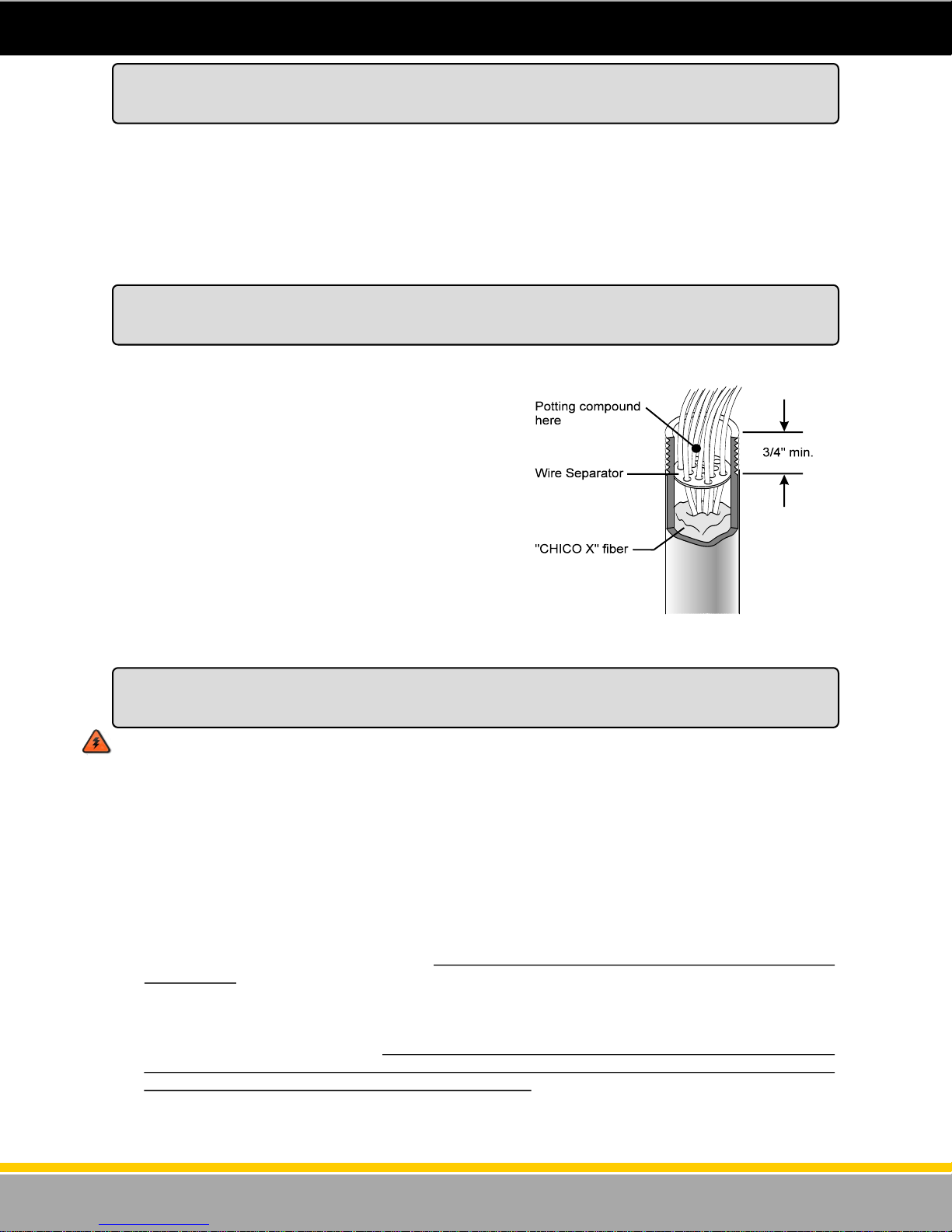
Installing the Wire Separator
Underwriters Laboratory, the local Fire Marshall and a
safe installation requires that a wire separator be
installed on the wires as they are routed through the
conduit and into the dispenser’s electronic enclosure.
The wire separator holds the wires apart to ensure that
the seal off compound fully seals around each wire.
Apply the seal off compound during the last step of the
installation. This will prevent gasoline fumes from
working their way into the electronic enclosure. The
wire separator is supplied in the plastic bag located
inside the dispenser electronic enclosure. Run each
field wire through a hole in the wire separator and then
push the wire separator into the conduit at least 3/4”.
Make sure the “Chico” type fiber material has already
been pushed into the conduit, around the wires as
shown in figure 15.
Figure 15 - Wire Separator
Proper Equipment Grounding
Instructions for Earth Grounding the Equipment
WARNING: Failure to properly ground the equipment can cause injury or damage to the
equipment and will void the Bennett limited warranty.
This product must be properly grounded. Each dispenser requires a 12-gauge Green earth ground wire.
Grounding provides a path of least resistance for electric current to reduce the risk of electric shock.
Grounding is also required to protect the dispenser’s computer from external electrical noise generating
devices. The ground wire connection must provide 1 ohm (or less) resistance to earth ground. To
establish a good earth ground, follow this procedure:
1. Connect a 12-gauge (minimum), green stranded wire to the grounding terminal on the electronics
enclosure deck. Only one ground wire is required per dispenser.
2. Pull the wire through the rigid metal conduit and connect it directly to the ground bar of the MAIN
electrical service panel, not a sub-panel. Do NOT rely on the metal conduits as a ground anywhere
in the system.
DO NOT USE WIRE NUTS ON GROUND WIRES. USE COMPRESSION CONNECTORS ONLY.
3. Do not daisy-chain ground wires. All ground circuits must be dedicated wires connected directly to
the ground bar in the main electrical panel. A direct connection to the site’s ground rod must be
connected to the ground bar in the main electrical panel.
25
120001 Rev K 1-19-18
Page 26
AC Power Installation
Each dispenser uses one 115V, 50/60 Hz or 230V, 50/60 Hz circuit for dispenser power. Make sure the
power source has the correct frequency and voltage. Connect the electrical circuit to the terminal strip
on the CPU board. Only one dispenser electronics Hot and Neutral needs to be pulled per dispenser.
That power will be jumped from Control Board to Control Board in the electronics head (at the factory) if
there is more than one Control Board in the dispenser.
All references to 115VAC in this manual can also be identified as 230VAC if the dispenser ordered is for
230 VAC. Note: 115VAC installations: L1 is hot and L2 is Neutral. In 230VAC installations: L1 is hot
and L2 is the other phase hot.
Electronic Power Connections:
1. Connect the White (Neutral) 14ga. wire in 115V circuits or the Red 14ga. wire in 230V circuits to
terminal 1 of TS2 on the CPU board. The CPU board is located on the upper electronics door.
2. Connect the Black (Hot) 14ga. wire to terminal 2 of TS2 on the CPU board.
3. Electronic power must be connected to a dedicated 15 amp. circuit breaker. Electronic power for all
dispensers at an installation must be wired to the same AC line phase or damage from cross phas-
ing will result in the remote sub-pump relay control circuits.
Rules to ensure proper operation:
1. Each dispenser uses one 115V, 50/60 Hz or 230V, 50/60 Hz circuit for dispenser power. Put no
more than two (2) dispensers on a circuit breaker (for Electronic Power).
2. Do not connect any other devices or motors to these circuits.
3. Put the pump wiring in its own separate conduit. Do not put non-pump related wires, such as price
signs or intercoms, in the same conduit as pump wiring.
4. Use only 14-gauge stranded gas and oil resistant THHN wire.
5. Do not use wire nuts anywhere in the pump wiring runs.
WARNING: All Dispenser AC Power circuits (for Remotes only) must be on the same phase or
damage will result to the dispenser power board or the sub-pump relay box.
Connecting Pump Motor Power for Remote Dispensers
Connecting the Sub Pump Control Wiring for Remote Dispensers
Remote dispensers require the use of submerged pumps. These pumps are located in the Underground
Storage Tank and are controlled by a “control relay”. The dispenser sends the signal to the control relay
to energize the submerged pump. Red Jacket and F.E. Petro are two of the most common manufactur-
ers of submerged pumps. Check with those manufacturers for more information on control relay boxes.
Connect the “Motor Out” power wires between the dispenser and the control relay box for each product
as follows:
Submerged Pump Motor Control - Connect to terminal 3 of TS2 on the CPU/Control board on side 1
of the dispenser. This should be a 14 ga. wire. If there is another CPU/Control board for this SAME
PRODUCT, install a jumper wire between terminal 3 of TS2 of both boards. This allows terminal 3 of
both boards to control the same submerged pump relay for that product. This should be a 14 ga. wire
also. It is recommended that for Product “A” the Installer use a Blue wire for submerged pump motor
control and if there is a second product (Product “B”) use a Brown wire for submerged pump motor con-
trol. Refer to the Remote Power Wiring Diagram section of this manual.
Note - Select Submerged Pump control or Suction Pump control by setting a jumper wire on the CPU.
Make sure that there is a jumper from P1 to P2 on the CPU if controlling a submerged pump relay. This
will be set at the factory.
26
120001 Rev K 1-19-18
Page 27
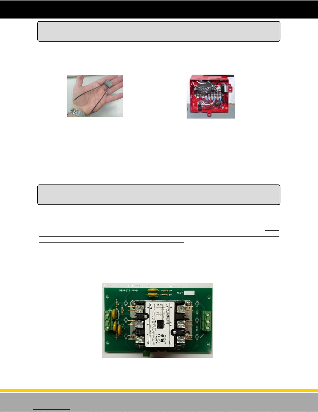
An RC Network is an electrical noise suppression device (see figure 16 and figure 17). It is used on AC
power devices such as coils and across relay contacts. When AC voltage is applied to coils they are
converted to electromagnets. Coils are used to operate AC devices, such as solenoid dispensing valves
and AC power relays or contactors. W hen the AC power is removed from a coil, the electromagnetic
field collapses. This causes an AC voltage spike as high as 1500 VAC which can affect electronic
systems.
Install the three RC Networks in the Control Relay Box across the following (Refer to the Remote Power
Wiring Diagram in the Wiring Section of this manual):
Figure 16 - An RC Network.
Installing RC Networks
For Submerged Pump Systems
Figure 17 - RC Networks installed in
control relay box.
Across Coil to Neutral
Across M1 to L1
Across M2 to L2
Check local code requirements concerning complete disconnect of submerged pump voltages. RC
Networks will allow voltage to be present at all times.
Connecting Pump Motor Power for Suction Pump Systems
Connecting Pump Motor Power for Self-Contained Pumps
Self-contained dispensers have the pump motor mounted in the lower hydraulic area. The power is
passed to the pump motor using the pump motor relay located on the CPU board in the electronic
enclosure. Use 14-gauge stranded THHN wire minimum for the suction pump motor wires for runs
under 50ft. 12Ga. for runs to 100ft, 10ga.for runs over 100ft, and 8 ga. for runs over 200 feet. Pump
motor power must be on a different phase leg than the dispenser power or system malfunction
will result and the Bennett Limited Warranty will be voided.
Termination of Field Wiring for Pump Motor Power of Self-Contained Dispensers
Note: Wire termination for 3-phase Motor Connections for 3000 series self-contained pumps with 210
or 531 electronics will be terminated directly to a 3-phase contactor relay or terminated to a
contactor board as shown in Figure 18.
Figure 18 - Contactor Board
27
120001 Rev K 1-19-18
Page 28
Connecting Pump Motor Power for Suction Pump Systems
Connecting Pump Motor Power for Self-Contained Pumps
Product “A” Suction Pump Motor Control (120VAC / 240VAC) - Connect the Blue 14ga. L1 - 120 or
240VAC (HOT) wire from the second motor power circuit breaker to terminal 4 of TS2 on the CPU
board. Connect the White 120VAC Neutral or the Black L2 240VAC wire from the motor power circuit
breaker directly to the pump motor neutral wire. Please refer to the Wiring Diagram located in the Wiring
Section of this manual or on the USB provided.
Product “B” Suction Pump Motor Power (120VAC / 240VAC) - Connect the Red 14ga. L1 - 120 or
240VAC (HOT) wire from the first motor power circuit breaker to terminal 4 of TS2 on the CPU board.
Connect the White 120VAC Neutral or the Black L2 240VAC wire from the motor power circuit breaker
directly to the pump motor neutral wire.
Note: Select the Submerged Pump control or Suction Pump control by setting a jumper wire on the
CPU. Make sure that there is NO jumper from P1 to P2 on the CPU board if controlling a
suction pump motor. This will be set at the factory.
3-Phase Suction Pump Motor Control (380VAC) - Connect the Brown 14ga. L1 - 380VAC (HOT) wire
from the first motor power circuit breaker directly to the 3-phase contactor relay or to TS2 terminal L1 on
the Contactor Board. Connect the Orange 380VAC (HOT) wire from the first motor power circuit breaker
to the 3-phase contactor relay or to TS2 terminal L2 on the Contactor Board. Connect the Yellow 14ga.
L3 - 380VAC (HOT) wire from the motor power circuit breaker directly to the 3-phase contactor relay or
to TS2 terminal L3 on the Contactor Board.
Note: Motors are 380VAC 50hz. Connections on factory supplied 3-phase contactor (relay).
Connecting the Communication Wires
For the RS-485 comm unication wires, use 18 gau ge, t wisted wi res at 3 twists per foot. Refer to
the RS-485 Wiring Diagram in the wiring section of this manual. Connect the RS485 communication
wires to TS1 on the CPU as follows:
TS1 - 5 RS485 Positive (+) Orange 18 ga.
TS1 - 6 RS485 Common Black 18 ga.
TS1 - 7 RS485 Negative (-) Brown 18 ga.
28
120001 Rev K 1-19-18
Page 29
Mechanical Mode - Mechanical Mode allows the 3000 series to imitate a mechanical dispenser and
interface to a Fleet System. It also allows pulse output communication with a Tank Gauge.
A separate Mechanical Pulse Output Interface Board is required for the dispenser. There will be one
Pulse Output board for a single product (single hose or twin) dispenser . The board can output two
channels (Side 1 and Side 2) of pulse information for a console and also for a tank gauge, handle switch
output for pump “in use” signal, and an input for an “authorization” signal for each side of the dispenser
for a product. The mechanical interface board is mounted on the deck inside the electronics enclosure.
This mechanical interface board also communicates with the CPU boards.
Pulse Output - The pulse output allow s the 3000 mechani cal i nterface to send pulse inf ormation
to the console and the Tank Gauge. The system can be programmed to output pulse ratios from 1:1,
10:1, 100:1, and 1000:1. The Fleet System connected to the dispenser must provide 5 - 12 volts DC for
the pulse output channel. The pulse output rate is determined with jumpers on the Pulse Output Board.
Refer to the Pulse Output Wiring Diagram in the back of this manual and the table on the next page to
see how to wire to the Pulse Output Board. The drawing shows how to wire directly to the pulse output
board OR, if there is an optional junction box installed, the correct wiring to the junction box. Also, the
table lists correct wiring to the Pulse Output Board OR to the optional junction box.
Handle Switch Signal— The handle switch signal can be used to signal the console that the pump is
“in use”. Some Fleet Systems require this signal and some do not. Refer to the Pulse Output Wiring
Diagram in the back of this manual and the table on the next page to see how to wire the handle switch
signals.
Authorization Signal - A Fleet System can send “authorization” to a fueling point (in the form of a 110
volt signal) which allows the fueling point to reset at the beginning of the sale. Without this signal, the
dispenser will not reset when in the “Mechanical” mode. Refer to the Pulse Output Wiring Diagram in the
back of this manual and the table on the next page to see how to wire the Authorization signals.
Tank Gauge Pulse Output Signals - The dispenser electronics Pulse Output Board can send pulse
information to the electronic Tank Gauge system so that it may reconcile dispensed product. The system
can be programmed to output pulse ratios from 1:1, 10:1, 100:1, and 1000:1. The Tank Gauge system
connected to the dispenser must provide 5 -12 volts DC for the pulse output channel. Refer to the Pulse
Output Wiring Diagram in the back of this manual and the table on the next page to see how to wire the
Tank Gauge signals.
Connecting Field Wiring to the
Mechanical Interface Board
29
120001 Rev K 1-19-18
Page 30

Pulse Output Field Wiring Table
(Also refer to as the Pulse Output Wiring Diagram)
Name Color Wire
Tank Gauge Out Product A side 1
Tank Gauge Out Product A side 1
Tank Gauge Out Product A side 2
Tank Gauge Out Product A side 2
Pulse Output Product A side 1
Pulse Output Product A side 1
Pulse Output Product A side 2
Pulse Output Product A side 2
Handle Product A side 1
Handle Product A side 1
Handle Product A side 2
Handle Product A side 2
Authorization Product A side 1
Authorization Product A side 2
Neutral Product A side 1
Pulse Output Product B side 1
Pulse Output Product B side 1
Pulse Output Product B side 2
Pulse Output Product B side 2
Handle Product B side 1
Handle Product B side 1
Handle Product B side 2
Handle Product B side 2
Authorization Product B side 1
Authorization Product B side 2
Neutral Product B side 2
Tank Gauge Out Product B side 1
Tank Gauge Out Product B side 1
Tank Gauge Out Product B side 2
Tank Gauge Out Product B side 2
(+)
(-)
(+)
(-)
(+)
(-)
(+)
(-)
(+)
(-)
(+)
(-)
(+)
(-)
(+)
(-)
(+)
(+)
(+)
(-)
(+)
(-)
(+)
(-)
Size
Gray 1(+) 18 Ga. Flying Lead Gray Product A
Gray 1(-) 18 Ga. Flying Lead Gray Product A
Pink 1(+) 18 Ga. Flying Lead Pink Product A
Pink 1(-) 18 Ga. Flying Lead Pink Product A
Red (+) 18 Ga. Position 1 in J-Box TS1-1 Pulse Output Board Product A
Red (-) 18 Ga. Position 2 in J-Box TS1-2 Pulse Output Board Product A
Orange (+) 18 Ga. Position 3 in J-Box TS1-5 Pulse Output Board Product A
Orange (-) 18 Ga. Position 4 in J-Box TS1-6 Pulse Output Board Product A
Violet 1(+) 18 Ga. Position 5 in J-Box TS2-9 Pulse Output Board Product A
Violet 1(-) 18 Ga. Position 6 in J-Box TS2-10 Pulse Output Board Product A
Blue 1(+) 18 Ga. Position 7 in J-Box TS2-11 Pulse Output Board Product A
Blue 1(-) 18 Ga. Position 8 in J-Box TS2-12 Pulse Output Board Product A
Brown 1A 18 Ga. Position 9 in J-Box TS3 - 13 Pulse Output Board Product A
Brown 1B 18 Ga. Position 10 in J-Box TS3 -15 Pulse Output Board Product A
White (1) 18 Ga. Position 11 in J-Box TS3-14 & 16 Pulse Output Board Product A
Yellow (+) 18 Ga. Position 12 in J-Box TS1-1 Pulse Output Board Product B
Yellow (-) 18 Ga. Position 13 in J-Box TS1-2 Pulse Output Board Product B
Black (+) 18 Ga. Position 14 in J-Box TS1-5 Pulse Output Board Product B
Black (-) 18 Ga. Position 15 in J-Box TS1-6 Pulse Output Board Product B
Violet 2(+) 18 Ga. Position 16 in J-Box TS2-9 Pulse Output Board Product B
Violet 2(-) 18 Ga. Position 17 in J-Box TS2-10 Pulse Output Board Product B
Blue 2(+) 18 Ga. Position 18 in J-Box TS2-11 Pulse Output Board Product B
Blue 2(-) 18 Ga. Position 19 in J-Box TS2-12 Pulse Output Board Product B
Brown 2A 18 Ga. Position 20 in J-Box TS3-13 Pulse Output Board Product B
Brown 2B 18 Ga. Position 21 in J-Box TS3-15 Pulse Output Board Product B
White (2) 18 Ga. Position 22 in J-Box TS3-14 & 16 Pulse Output Board Product B
Gray 2(+) 18 Ga. Flying Lead Gray Product B
Gray 2(-) 18 Ga. Flying Lead Gray Product B
Pink 2(+) 18 Ga. Flying Lead Pink Product B
Pink 2(-) 18 Ga. Flying Lead Pink Product B
J-Box Connection
(Optional)
Marked 1(+)
Marked 1(-)
TS1 - 7 Pulse Output Board Product A
Marked 1(+)
TS1– 8 Pulse Output Board Product A
Marked 1(-)
TS1- 3 Pulse Output Board Product B
Marked 2(+)
Marked 2(-)
Marked 2 (+)
Marked 2 (-)
Board Connection
TS1-3 Pulse Output Board Product A
TS1-4 Pulse Output Board Product A
TS1-4 Pulse Output Board Product B
TS1-7 Pulse Output Board Product B
TS1-8 Pulse Output Board Product B
30
120001 Rev K 1-19-18
Page 31
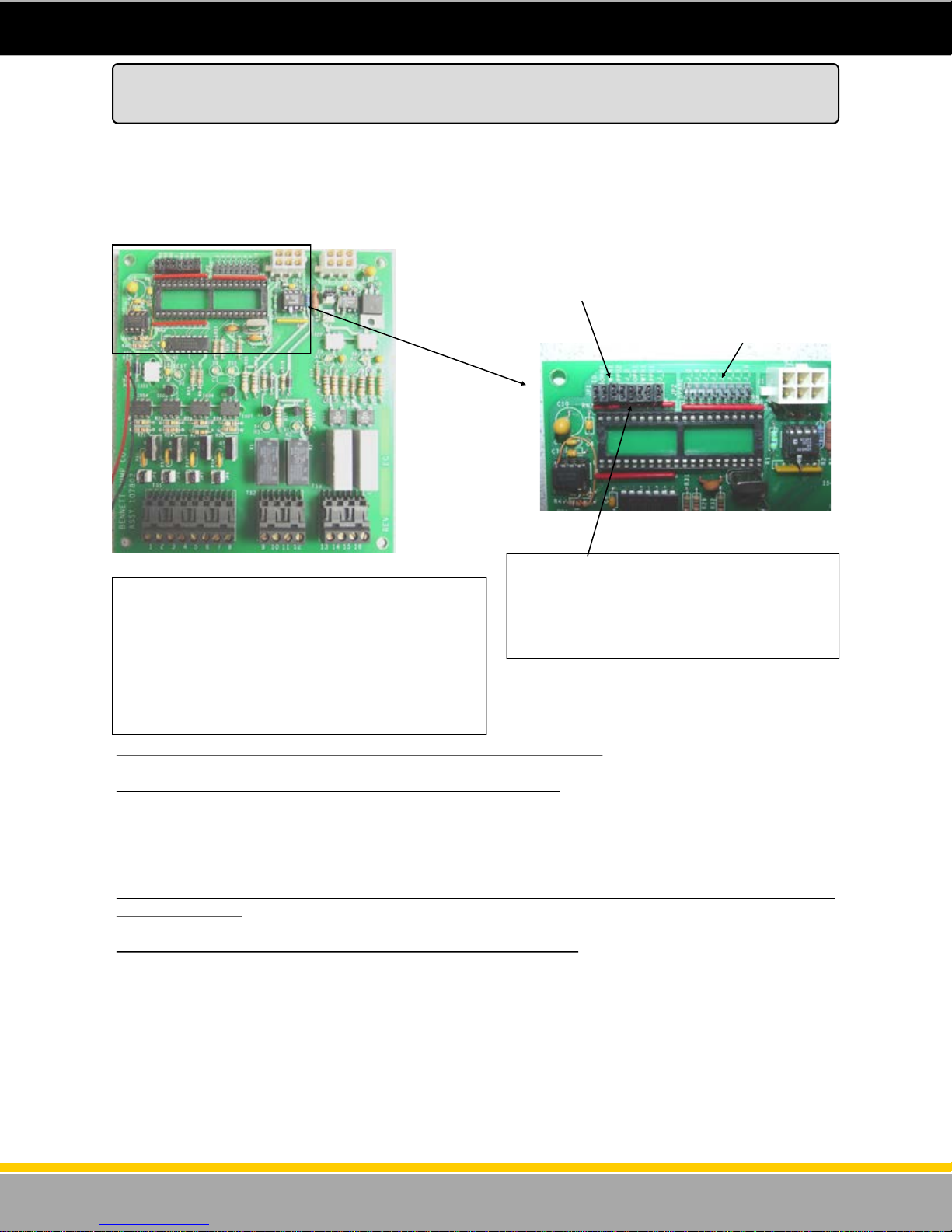
Setting the Jumpers on the Pulse Output Board
The Pulse Output board is ordered as an option with the Electronic 3000 series. This board is where the
field wires connect the 3rd party Fleet System to the Pulse Output functions of the dispenser. This
board also has jumpers that need to be set to determine the Pulse Rate and the Pulse Width. Whatever
pulse rate is set will send the same pulse rate and width to both the Fleet System and the Tank Gauge
(if one is connected). This section describes how to set these jumpers. Refer to the Figures below:
JP1-1,2,3,4,and 5 are used to set the pulse rate and pulse width.
JP2 is currently not used.
Figure 20 - Pulse Output Board Jumpers
Figure 19 - Pulse Output Board
This is the Pulse Output Board. It has the terminal
strips for the field wire connections along the bottom
of the board to communicate with the Fleet System
using a pump handle output signal, an authorize input signal and a pulse train signal. The Jumper
Header JP1 is at the top left of the board. These
jumpers must be set to determine the pulse rate and
the pulse width. See information below.
To set the Pulse Rate Output, set jumpers JP1-1 and JP1-2 as follows:
JP1-1 JP1-2 Pulses Per Gallon Pulses per Liter
OUT OUT 1000 100
IN OUT 100 10
OUT IN 10 1
IN IN 1 1/10TH
To set Pulse Width, set jumpers JP1-3, JP1-4, JP1-5 as follows (PULSE WIDTH’S ARE IN
MILLISECONDS):
JP1-3 JP1-4 JP1-5 Pulse Width Pulses Per Minute
OUT OUT OUT .5 ms 60000
IN OUT OUT 1 ms 30000
OUT IN OUT 2 ms 15000
IN IN OUT 4 ms 7500
OUT OUT IN 8 ms 3750
IN OUT IN 16 ms 1875
OUT IN IN 32 ms 9378
IN IN IN 64 ms 467
The top left of the Pulse Output board has a
jumper header called JP1. It has 8 jumper
positions. Set the Pulse Rate with the first two
jumpers and the Pulse Width with the 3rd, 4th
and 5th. See information below.
31
120001 Rev K 1-19-18
Page 32
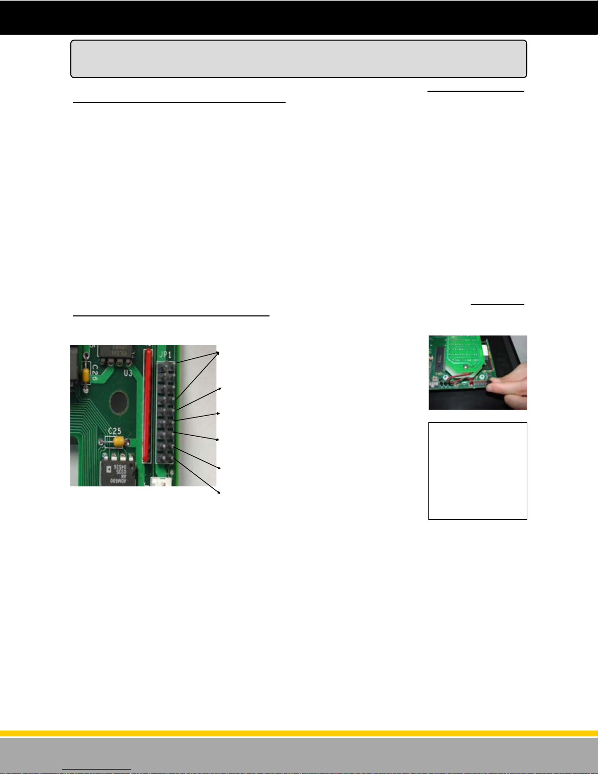
CPU Board Jumper Configuration
The 3700 Series can operate in two different modes, Console or Stand Alone, which must also be
defined by jumper settings on the CPU board:
Stand Alone Mode -Stand Alone mode allows the 3700 Series to operate without being connected to a
console or control device. In this mode, when the handle is turned “on” the dispenser authorizes itself.
Console Mode - Console mode allows the 3700 Series to communicate with compatible consoles or
control devices using a RS485 communication data loop. Also, the dispenser is also set for Console
mode when operating in mechanical mode with a Pulse Output board to a Fleet System. See below.
Mechanical Mode - Mechanical mode allows the 3700 Series to imitate a mechanical pump and
interface to a Fleet System. There is no actual “mechanical mode” to select. For this type of interface,
a separate “pulse output” board must be ordered with the system and the Console mode must be
selected. So, to put the system into “Mechanical Mode” install a Pulse Output Board and select the
Console Mode w ith the jump er. The field wires between the Fleet System and the dispen ser
would be connected to the Pulse Output Board. This board would be used to output pulse data, handle
switch status information and would receive authorization signals from the Fleet System. When setting
the system up to imitate a mechanical dispenser, select CONSOLE mode. See the following section.
The 3700 series dispensers are programmed using “jumpers” or “shunts”. The jumper header JP1 is a
9 position header and is located on the top right corner on the back of the CPU/Board. This jumper
header is used to program the dispenser (see f igure 21). Jumper configur at ion chang es may be
required on the CPU circuit board at the site. See the chart below for a quick reference of what the
jumpers do. See the next page for an explanation of each jumper setting.
JP1-1 through JP1-4 - Fueling Point Address .
See Next Page.
JP1-5 - Console or Stand Alone Mode
Figure 21 - CPU Jumpers on JP1
Console Mode - Setting Jumpers
JP1-6 - Suction Pump Motor Delay
JP1-7 - Leak Detector Pre-charge
JP1-8 - Imperial Gallons
JP1-9 - Units
Figure 22 - JP1 Position
Jumper Header JP1 is
located on the top right of
the back of the CPU /
Control board. This board
is mounted to the upper
door. It has 9 positions.
Jumpers should be set
with dispenser power off.
The jumper settings are
only read on “power up”.
The 3700 Series is shipped from the factory configured for the console mode of operation. In the
“Console” mode, the 3700 electronic commercial dispenser can communicate with any console that can
communicate using RS485 communication. It is also set for Console when using the mechanical
interface pulse output board. When in the “Console” mode, after the handle is lifted, the dispenser must
receive the “authorization” command from the console or controlling device before the dispenser resets
and begins the sale.
Jumper Header JP1 is a 9 position jumper header (see figure 22). Position 5 is for setting the dispenser
in the Console or Stand Alone mode. Placing the jumper across the pins on position 5 puts the
dispenser in Console mode.
This jumper configures the CPU for RS485 output on TS1 (Field wire connection to the Console).
TS1-7 = DATA (–)
TS1- 6 = DATA (Common)
TS1 - 5 = Data (+)
32
120001 Rev K 1-19-18
Page 33
CPU Board Jumper Configuration
Stand Alone Mode - Setting Jumpers
In the Stand Alone mode, the dispenser does not require an outside “authorization” signal from any
console or control unit. When the handle is lifted, the dispenser “authorizes” itself and the dispenser
resets and the sale begins.
Jumper Header JP1 is a 9 pin jumper header. Position 5 is for putting the dispenser in the “Stand
Alone” or “Console” mode. Removing the jumper from JP1 position 5 puts the dispenser in the Stand
Alone mode.
Setting the Jumpers— The jumpers should be set with power off and are only “read” at boot-up (power
up).
WARNING - DO NOT SET OR REMOVE JUMPERS WITH DISPENSER POWER TURNED ON!
DAMAGE TO THE DISPENSER MAY RESULT. ALWAYS MAKE SURE DISPENSER POWER IS OFF
AND THE BACK-UP BATTERY IS BYPASSED WHEN ADDING OR REMOVING JUMPERS!
The 9 position Jumper Header is located on the CPU board. It is used to set the hose position address
and to program the dispenser.
Jumper Positions 1 - 4 - (Fueling Point Address - Up to 16 fueling position addresses). Use jumper
positions 1 through 4 to set the dispenser address. Normally, Bennett pumps do not need an address
set when using current loop communications but with RS 485 style communication an address must be
set for the 3rd party device or console to know which fueling point it is talking to. The first four rows of
pins (on jumper header JP1) represent a binary number whose greatest value is 16 (or 0-15). The
fueling point address must be set to identify each hose position / fueling point using these jumpers. See
the chart on the next page for details on how to set the address for a specific fueling point number using
the jumpers on the first four rows of jumper header JP-1.
Jumper Position 5 - Console or Stand Alone -
In - Console (or Mechanical)
Out - Stand Alone
Jumper Position 6 - Motor delay (suction pumps without valves). This function allows a 2 second delay
preventing the dispenser from turning on immediately when the pump handle is lifted. This would be
used on a dispenser with self contained pumps and no valves. Set the dispenser for the two second
delay so that the motor does not come on immediately when the handle is thrown allowing the dispenser
to pump through a hose without a valve before the dispenser resets.
In - 2 second delay
Out - No Delay
Jumper Position 7 - Leak Detector Pre-charge - This function allows the system to energize the
submerged pump pressurizing the line to check for leaks before the valve opens. The jumper should be
out in most cases unless the leak detectors routinely trip (very slow flow from the nozzle - then use 9
seconds).
In - 9 seconds
Out - 2 seconds
Jumper Position 8 - Imperial Gallons (see figure 23)
In - Imperial Gallons
Out - Gallons
Jumper Position 9 - Units (see figure 23)
In - Liters
Out - Gallons
Imperial Gallons In Out
Gallons Out Out
Liters Out In
Figure 23 - Using Jumpers 8 & 9 to set Gallons
or Liters.
Position 8 Position 9
33
120001 Rev K 1-19-18
Page 34
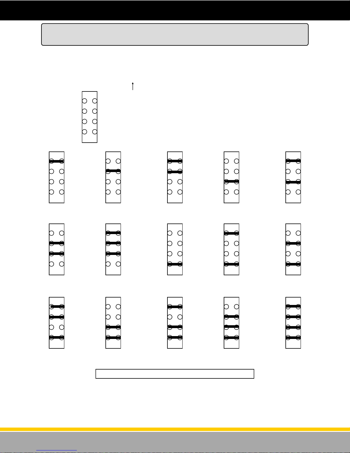
CPU Board Jumper Configuration
Jumper Header JP1 on the CPU board is used to program the dispenser and to set the hose position
address. The first 4 rows are used to set the hose position address. Addresses from 1-16 are available.
Figure 24 shows how to set the address using the first four rows of the Jumper Header.
Setting the Fueling Point Address using jumpers on
JP1 header - First four rows - Top of Board
Address 1 -
No Jumpers
Row 1
Row 2
Row 3
Row 4
jumper header JP1 top right corner of the CPU/
Control Board. The dark line indicates the shunt
jumper installed.
Address 2
Address 7 Address 8
Address 12
Figure 24 - Jumpers 1 through 4. Setting the Fueling Point Address.
Address 9
Address 6 Address 5 Address 4 Address 3
Address 10 Address 11
Address 16 Address 15 Address 14 Address 13
34
120001 Rev K 1-19-18
Page 35
Dispenser Startup and Checklist
DANGER: Fire, explosion, injury or death will occur if fuel vapors are present. Make sure there
are no vapors present before starting this procedure.
CAUTION: To prevent damage to the dispenser, follow the proper start-up procedures.
Before applying AC power to the dispenser, follow this procedure:
1. Unlock and open the upper and lower dispenser doors.
2. Check to make sure:
The boards and other components have not come loose from shipping. LCD display boards are
not cracked or damaged.
The cables are properly connected to the boards. There are no torn cables or stranded
harnesses.
Pulser and pump handle harnesses are connected properly to the CPU board.
3. Make sure the shut off valves are closed.
4. Turn off all submerged pump circuit breakers and all other circuit breakers to the dispenser.
Make sure the 12-gauge green ground wire is properly connected and measures 1 ohm (or less)
resistance to earth ground. This measurement should be taken between neutral and ground at the
dispenser. When taking this measurement, make sure the ground and the neutral are disconnected at
the dispenser. This ensures that the resistance read is not across the electronics on the circuit board. If
the resistance reading is more than 1 ohm, the dispenser electronics may not operate properly and will
void the Bennett Limited Warranty.
Turn on 115 or 230 Volts AC dispenser power to the unit.
1. Use a voltmeter to verify 115 or 230 Volts AC only at Terminal 2 on TS2 of the CPU board. Terminal
1 of TS2 on the CPU board is Neutral. This AC circuit provides power to the electronic boards.
2. Make sure displays are normal and not garbled.
WARNING: Make sure all dispenser power circuits for REMOTES ONLY are on the same phase/
leg of the breaker panel or damage will result.
3. Turn the dispenser power off. Program the dispenser for Stand Alone operation by removing the
jumper from JP1 jumper 5 . (Do not lose this jumper because it may be needed again later). Refer
to the previous section for jumper settings. Turn the dispenser power back on.
CHECK THE PUMP MOTOR CIRCUIT
Remotes
WARNING: To prevent injury, make sure impact valves and submerged pump breakers are off.
1. Put the 1st Product’s pump handle in the ON position. The dispenser display will reset. Use a
voltmeter to verify 115 or 230 Volts AC on Terminal 3 on TS2. Use Terminal 1 as neutral.
2. Put the 1st Product pump handle in the OFF position.
3. Repeat this process for the remaining hose positions.
4. Turn on all handles for the same product and make sure the dispensers are operating properly.
Make sure all dispensers for each product are on the same phase of power. The dispensers should
not be on different phases of power.
5. Open and set the impact valves.
35
120001 Rev K 1-19-18
Page 36
Dispenser Startup and Checklist
Self-Contained
WARNING: If the lower door on the pulley side of the unit is off, close the door and lock it to
prevent injury.
1. Verify that the motor voltage select switch on the self contained motor is in the proper position. (if
applicable)
2. Turn on the 1st Product pump motor circuit breaker. With the pump handle OFF, use a voltmeter to
verify 115/230 Volts AC power for the self contained pump motor by measuring between (Hot)
terminal 4 on TS2 of the CPU and (Neutral) terminal 1 of TS2 of the CPU board. Also, if this is a
230 volt A.C. power circuit for the suction pump motor, check between terminal 4 of TS2 on the CPU
board and neutral of the pump motor. The pump motor has two wires coming into the dispenser
head from the motor. One lead connects to the dispenser electronics (factory connected) and the
other lead is for the installer to run the neutral return. If the motor is being operated off of 230 volts,
this is the other phase leg for the suction pump motor. The solid state relay for the suction pump
motor is located on the CPU board. The 1st Product pump motor should not be running at this time.
3. Turn off the 1st Product pump motor circuit breaker.
4. Repeat this test for the remaining hose positions.
All Dispensers
1. Turn off all circuit breakers.
2. Close and lock the lower doors and the upper doors.
3. Turn the circuit breaker for the system on.
4. Purge the air from the system.
5. Dispense a small amount of fuel from each hose to verify all positions are counting.
Proceed to the section for finishing the installation called “Potting Instructions”.
36
120001 Rev K 1-19-18
Page 37

Potting Instructions
1. Install field conduit in the dispenser per NFPA-70 along with
any state and local codes.
2. Pull field wiring allowing 72 inches of extra wire to reach upper
electrical enclosure.
3. Feed wire through conduit and into upper electrical enclosure
CAUTION: Do not damage wire while feeding through
conduit into the upper electrical enclosure.
4. Wrap some “CHICOX” fiber around wires and push into conduit
assembly to prevent potting from running down the length of
the conduit (see figure 24).
5. Using the wire separator provided, install one wire in each hole
until all wires are separated (see figure 25).
6. Push wire separator at least 3/4” into conduit.
7. Prepare potting compound according to directions.
NOTE: Use “CHICO A3” potting compound for sealing
fittings in hazardous locations.
8. Using a funnel, pour potting into conduit, be sure to get potting
in between each wire (see figure 25).
9. Let stand until firm.
10. Shorten field wiring to appropriate length when making
connections
11. Attach field wiring to terminal strip in upper electrical enclosure
according to the wiring diagram supplied for this dispenser (see
figure 26).
Figure 25 - Potting Instructions
Figure 26 - Wire Termination
37
120001 Rev K 1-19-18
Page 38
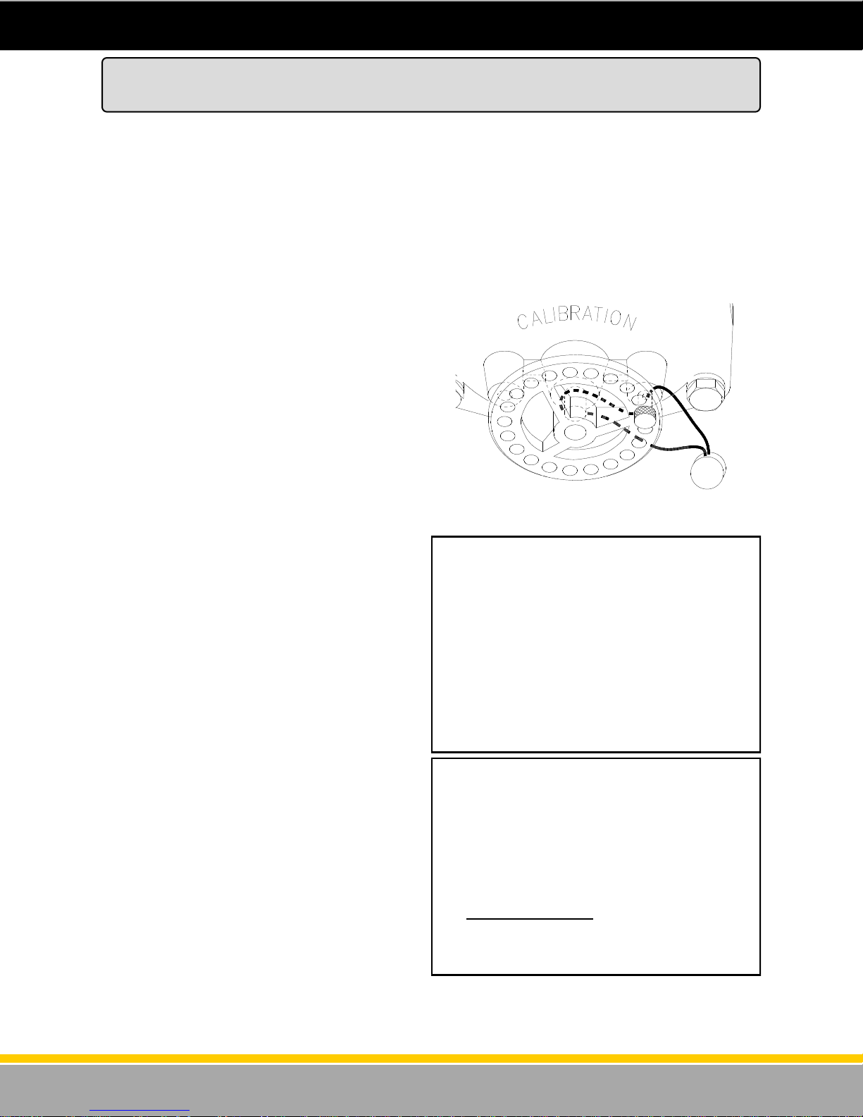
How to Mechanically Calibrate the SB-100 Meter
(M-Cal Option)
The Bennett SB-100 Meter is built to maintain accurate measurement under normal operating
conditions. The meter is a positive displacement device with rods and pistons, which require a break in
period. The meter is calibrated at the factory using a solvent for safety purposes and must be calibrated
after it has been installed. We strongly suggest recalibration of the meter after a 90 day break in period.
With the 3700 series electronic dispenser, mechanical calibration is optional. The standard 3700 is
calibrated electronically. This means that the meter in the dispenser may not be able to be calibrated
mechanically (it will not have a mechanical calibration wheel). If the meter on the dispenser does not
have the mechanical calibration wheel on it then it will be required to use the electronic calibration
option. Go to the next section in this manual that explains how to perform an electronic calibration.
The dial adjusting cover has (+) and (-) arrows to
indicate the correct direction to rotate the dial to
either increase or decrease delivery.
The dial cover has two pin hubs, one to the left of
the shaft and one to the right. The seal pin may be
inserted in either hub (see figure 27). The smallest
adjustment (.6 cu. in.) occurs when the pin is pulled
from one side and inserted in the other side by
moving the dial the least amount or half a hole. A
1.2 cu. in. adjustment is made by pulling the pin
and turning the dial until the next adjacent hole
aligns with the same hub and reinserting the pin.
To calibrate the meter, follow this procedure:
1. Measure the actual delivery of the meter at fast
flow in an accurate test measure. Dispense a
minimum of 5 gallons (20 liters).
2. Cut and remove the existing seal wires and
remove the seal pin (see figure 27).
3. Turn the dial the necessary amount in the (+)
or (-) direction to increase or decrease the
quantity of fuel delivered.
4. Re-insert the seal pin in the desired pin hub.
5. Dispense 5 gallons (20 liters) of fuel to allow
the meter to adjust to the new settings. Do not
make any adjustments based on this delivery.
6. Make sure the meter is properly calibrated.
1. A fast flow test at 11 GPM shows a +3 cu. in.
reading in a five gallon test measure.
2. Remove the existing seal and pin and turn the
dial clockwise (-)five minimum adjustments
(half holes) and reinsert the pin.
3 cu. in. = 5 half holes (-)CW
.6 cu. in./adjustment
3. Test and reseal.
Figure 27 - Calibration Wheel
Example 1
Dispense another 5 gallons (20 liters) of fuel
into an official test measure to check the
calibration.
1. A fast flow test at 11 GPM shows a -2 cu. in.
reading in a five gallon test measure.
2. Remove the existing seal and pin and turn the
dial counterclockwise (+) three minimum
adjustments (half holes) and reinsert the pin.
2 cu. in. = 3 half holes (+) CCW
.6 cu. in./adjustment
3. Test and reseal
Example 2
38
120001 Rev K 1-19-18
Page 39
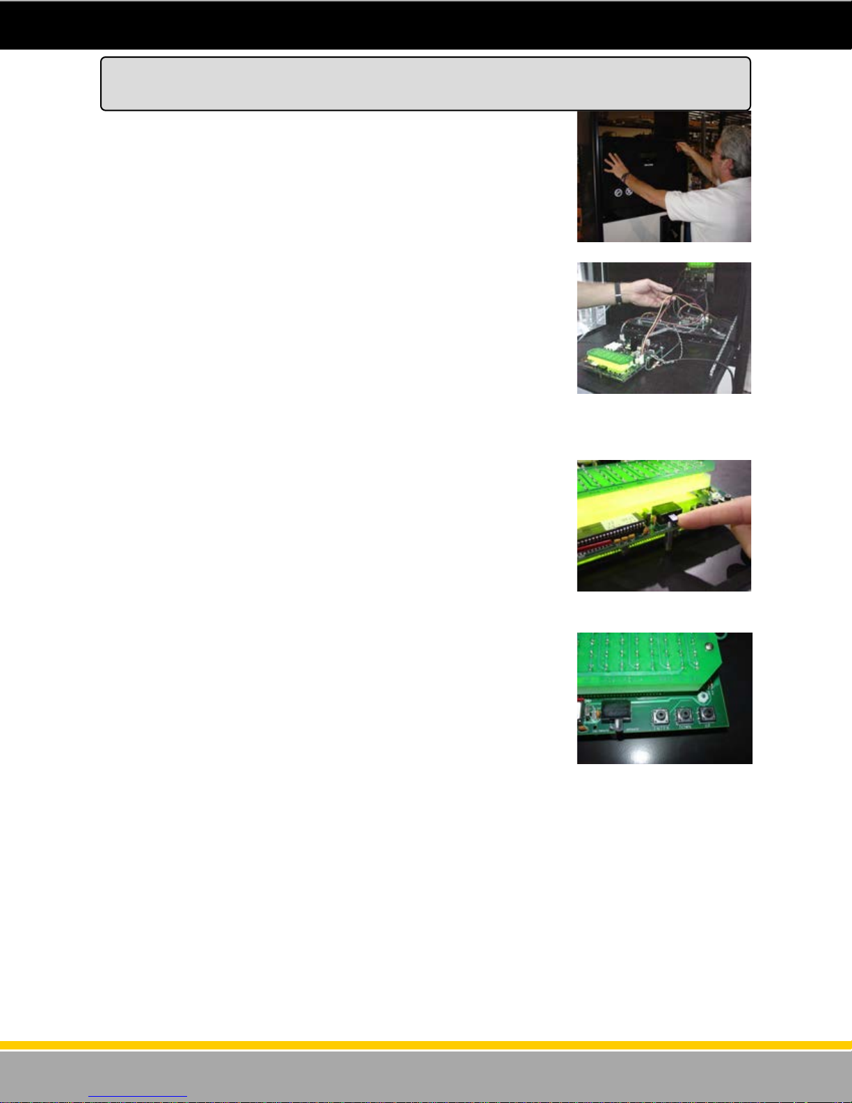
Electronic calibration is a simple method to calibrate the meters in the
dispenser. This method uses a mathematical algorithm in the software to
account for meter wear rather than mechanical methods to limit the piston
throw within the meter.
This method also eliminates the parts associated with mechanical
calibration in the meter. The result is a more symmetrical meter that will be
intrinsically more accurate.
Follow these steps to electronically calibrate the meter:
Step 1 - Pump 5 gallons, as displayed on the dispenser display, into the test
can. Make sure to stop pumping at exactly 5.000 gallons.
Step 2 - Read the plus / minus value in the test can.
Step 3 - Unlock and open the electronics door on the side with the meter
that is being calibrated (see figure 28). IMPORTANT - Make sure to
calibrate the correct meter! To make sure, locate the meter that is being
worked on and the valve that is connected to it. Follow those valve wires to
the correct CPU/Control Board to ensure that the correct meter is being
electronically calibrated (see figure 29). With the power on, locate the
electronic calibration switch on the top of the CPU/Display board, which is
mounted to the door (see figure 30).
Step 4 - Break the seal and move the switch to the calibrate position. Close
the door. The display should read the current calibration value.
Step 5 - Press the “Enter” button along the top edge of the CPU/Display
board. Figure 31 shows that there are 3 buttons next to the electronic
calibration switch. The functions of the buttons are “Enter”, “Up”, and
“Down”. Use these buttons to enter electronic calibration data.
How to Electronically Calibrate the SB-100 Meter
(E-Cal Option)
Figure 28 - Open the upper door.
Figure 29 - Follow the valve wires
from the meter you are
calibrating to make sure you are
calibrating the correct meter.
Figure 30 - Remove the seal and
turn the e-cal switch “ON”.
39
Figure 31 - “Enter”, “Up” and
“Down” keys used to input data.
120001 Rev K 1-19-18
Page 40
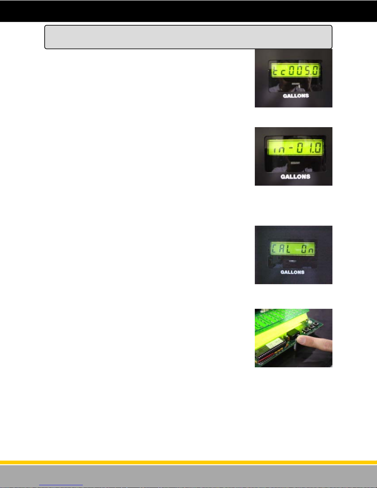
Step 6 - The display should say “tc 000.0” (see figure 32). Enter the Test
Can size that is used for this procedure. Do this by using the “Up” key on
the top of the board. (Typically 5 gallons or 20 liters). Press the “Enter”
button.
Step 7 – Enter the value of the measurement dispensed in the test can, this
will be a positive or negative amount (above or below the “0” mark). If the
test can measurement was “above” by 2 cubic inches, press the “Up” button
twice. If the measurement in the test can was “below” , for example, -1
cubic inch, change the sign to (-) minus by pressing the “down” button so
that the display shows “in –01.0” (see figure 33) . Press the “Enter” button
for the system to accept the information.
Step 8 - The system displays a message that shows “Cal On” with the
current calibration parameter (see figure 34).
Step 9 - Turn the ecal switch to the “Off” position and reseal (see figure 35).
How to Electronically Calibrate the SB-100 Meter
(E-Cal Option)
Figure 32 - Enter test can sample. In this example - 5 gallons.
Figure 33 - Entering a value that
represents a test can reading that
was “low” by 1 cubic inch. Any
low reading (in the test can) will
always be input as a negative
number.
Figure 34 - After inputting calibra-
tion value, it should show “Cal
ON”.
Figure 35 - Turn the e-cal switch
off when finished.
40
120001 Rev K 1-19-18
Page 41
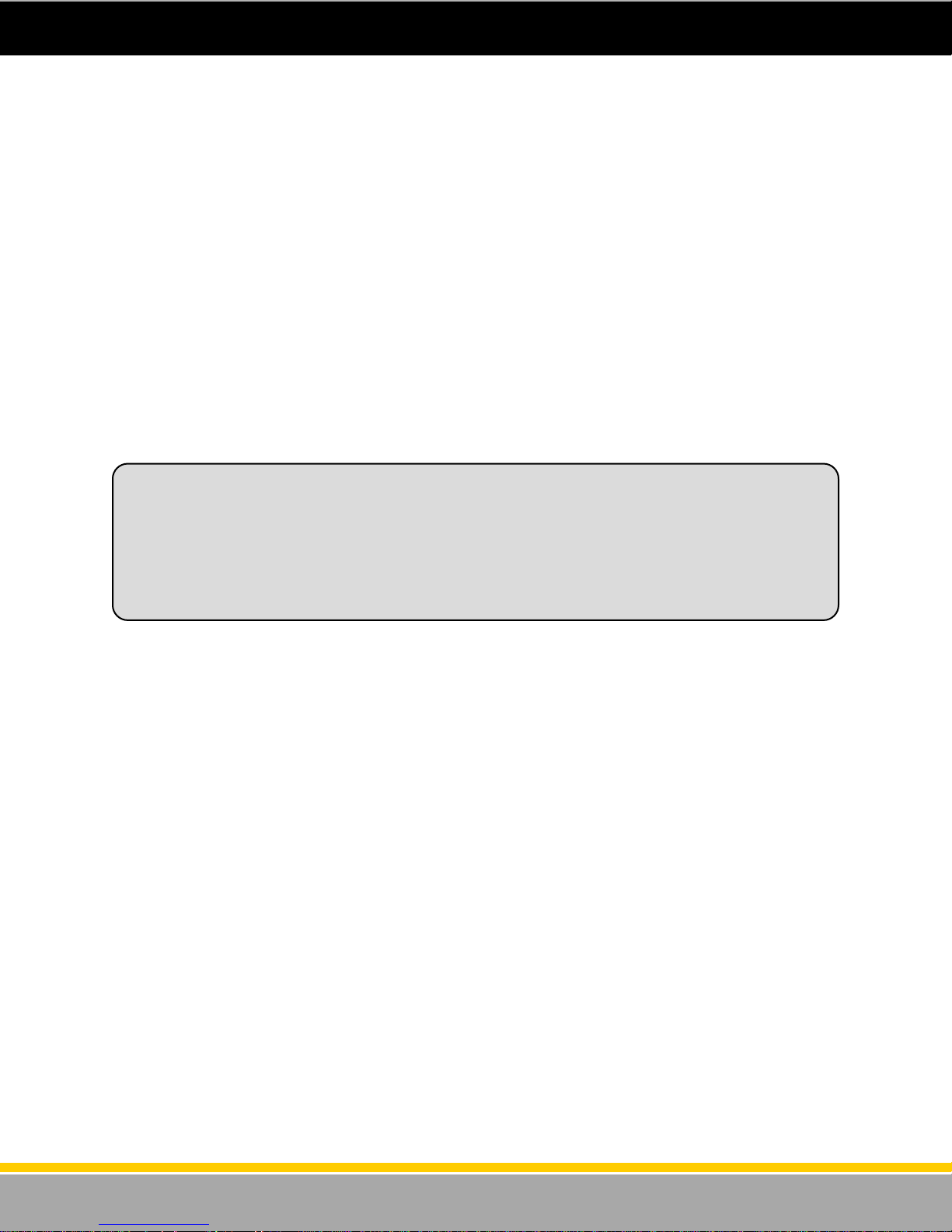
Wiring the 3800 Series
Dispenser
Retail
See General Wiring Requirements on pages 16, 17
41
120001 Rev K 1-19-18
Page 42

The 210 retail electronics package in the model 3800 unit is a very simple design. There will be one
“control” (CPU) board per hose. The dispenser may be ordered as a one or two hose unit. One hose
units will have one control board, two hose units will have two control boards. The control board is where
the field wires will connect if the optional junction box is not ordered. The installer will only have to run
dispenser power to side 1 product “A” CPU/Control Board. If there is more than one CPU/Control board,
the boards are factory wired for power from board to board. That is, power from board to board is wired
at the factory. Please refer to the Remote Power Wiring Section of this manual. Each control board will
be wired as follows:
Determine the wires needed in each step and add the number of wires from each step together to
determine total number of wires required.
Step 1. Dispenser Power - Every model of 3800 requires these wires:
(1) 12ga. Green ground wire
(1) 14ga Black L1 power wire for electronics power.
(1) 14ga. White for 115V neutral or red for 230V L2, for electronics power.
Step 2. Communications Wiring - For communications, the 210 electronics can communicate using 2
wire current loop or 3 wire RS-485. If the dispenser is to be connected to a control console using the
Current Loop protocol, rem ote communi cation w i res will be needed . Run 2 separate wires f or
each current loop channel. Refer to the Current Loop Communication Wiring Section of this manual
and follow these guidelines:
Current Loop - For each Hose Position (CPU): (1) 18ga. wire for communication positive (+)
(1) 18ga. wire for communications negative (-)
*Note - Follow the recommended color coding found in the wiring diagram.
RS - 485 Protocol - When using RS - 485 communication, 3 communication wires will be needed for
each dispenser. Even if there is more than one CPU/Control Board, only 3 wires are needed for the
entire dispenser. Refer to the RS-485 Communication Wiring Diagram.
To side 1 Product “A” only (CPU): (1) 18ga. wire for RS485 communication positive. (Orange)
(1) 18ga. wire for RS485 communication negative. (Brown)
(1) 18ga. wire for RS485 communication common. (Black)
Step 3. Remote Dispensers (Submerged Pump) - A remote relay control wire will be required for
each plumbed product. If there is only one product, only one control wire is needed. If there are two
products then two control wires are needed. Please refer to the Remote Power Wiring Diagram in the
wiring section of this manual.
For Product “A” : (1) Blue 14ga. w i re.
For Product “B” : (1) Brown 14ga. w ire
Step 4. For Self-Contained (Suction Pump) - A separate circuit and circuit breaker will be required for
each pumping unit motor. Place the pumping unit motor power circuit breakers on the opposite phase
from the dispenser’s electronic power or on 230VAC. This will keep the dispenser’s electronic power
free from electronic noise. The dispenser may have one motor (single product) or two motors (dual
product). Each motor requires two field wires. Please refer to the Self Contained Power Wiring diagram
located in the wiring section of this manual.
Needed for each Pumping Un it Motor :
Note: Runs longer than 50ft. will require larger wires. Size wires to minimize voltage loss or run the
motors on 230V circuits to minimize the current in the wires.
Determining the Number of Wires Needed
(115 or 230 Volt Installations)
(1) Red for L2 Hot & (1) White 14ga. Neutral on 115V circuits
(1) Red for L2 Hot & (1) Black for L1 Hot for 230V circuits.
OR
42
120001 Rev K 1-19-18
Page 43
Step 5. Mechanical Pulse Output - If the dispenser is to be wired to a mechanical interface card/key
system, the following wires will be needed:
(2) Pulse output wires per CPU/Control Board (+) and (-) 18 ga. *
(2) Pulse output wires per CPU/Control Board for tank gauge interface (+) and (-) 18 ga. * (If applicable)
(2) Handle circuit wires per CPU/Control Board (+) and (-) 18 ga. *
(1) Authorization wires per CPU/Control Board (+) and (-) 18 ga. *
Note - The field wiring will be connected between a Bennett Pulse Output Board and the third party
interface system. This board will be mounted on the deck inside the electronics enclosure. One Pulse
Output Board can handle two CPU/Control Boards per Product. There can be a maximum of two
Bennett Pulse Output boards per dispenser. Please refer to the Pulse Output Wiring Diagram located in
the Wiring Section of this manual.
IMPORTANT NOTE - Wh en t he d ispenser is ordered as a “ Dual” AND t he Pulse Ou tput will tie to
a Tank Gauge System, the Installer will be required to pull many wires to the dispenser. In this case, the
dispenser should be ordered with a second “optional” field wire conduit and a second conduit for field
wires should be run to the dispenser.
*Note - The Installer should follow the recommended color coding for field wires found in the Pulse
Output Wiring Diagram section of this manual.
Note - When the system has the Mechanical Pulse Output Option the installer will not need to run
current loop or RS485 communication wiring.
Step 6. Intercom Systems - If the dispenser is ordered with an intercom (speaker and call button) the
Installer must pull wires for it.
The following wires are required:
(2) Speaker wires 18 ga.
(2) Call Button (optional) 18 ga.
* Run these wires in separate conduit. Do NOT run with dispenser electronic wires.
WARNING - DO NOT PULL INTERCOM WIRING WITH DISPENSER WIRING IN THE SAME
CONDUIT! INTERCOM WIRING AND DISPENSER WIRING SHOULD BE RUN IN SEPARATE
CONDUITS TO THE DISPENSER. INTERCOM SYSTEM MALFUNCTION WILL OCCUR IF THESE
WIRES SHARE THE SAME CONDUIT.
Refer to the Wiring Diagram section of this manual for Intercom Wiring.
Determining the Number of Wires Needed (Cont’d)
(115 or 230 Volt Installations)
43
120001 Rev K 1-19-18
Page 44
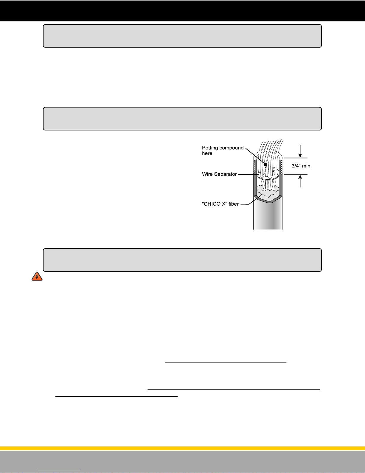
Pulling the Field Wires
Open the lower door on the dispenser on side 1 and locate the inlet wiring electrical conduit. The
conduit is located on side 1 in the center. This conduit is where all of the field wires will be pulled into
the Electronics enclosure. Side 1 of the dispenser is the side with the serial plate on the inside deck. If
this dispenser was ordered with a junction box, open the explosion proof junction box. The junction box
is located on side 1 in the lower (hydraulics) area. Otherwise, open the upper electronics enclosure door
on side 1 and locate the field wiring conduit. Pull the dispenser wires through the underground conduit
and into the upper electronic enclosure. Make sure that the copper ends of the wires are clean and free
of oxidation.
Installing the Wire Separator
Underwriters Laboratory, the local Fire Marshall and a
safe installation requires that a wire separator be
installed on the wires as they are routed through the
conduit and into the dispenser’s electronic enclosure.
The wire separator holds the wires apart to ensure that
the seal off compound fully seals around each wire.
Apply the seal off compound during the last step of
installation. This will prevent gasoline fumes from
working their way into the electronic enclosure. The
wire separator is supplied in the plastic bag located
inside the dispenser electronic enclosure. Run each
field wire through a hole in the wire separator and then
push the wire separator into the conduit at least 3/4”.
Make sure the “Chico” type fiber material has already
been pushed into the conduit, around the wires as
shown in figure 36.
Figure 36 - Wire Separator
Proper Equipment Grounding
Instructions for Earth Grounding the Equipment
WARNING: Failure to properly ground the equipment can cause injury or damage to the
equipment and will void the Bennett limited warranty.
This product must be properly grounded. Each dispenser requires a 12-gauge Green earth ground wire.
Grounding provides a path of least resistance for electric current to reduce the risk of electric shock.
Grounding is also required to protect the dispenser’s computer from external electrical noise generating
devices. The ground wire connection must provide 1 ohm (or less) resistance to earth ground. To
establish a good earth ground, follow this procedure:
1. Connect a 12-gauge (minimum), green stranded wire to the grounding screw on the electronics
enclosure deck.
2. Pull the wire through the rigid metal conduit and connect it directly to the ground bar of the MAIN
electrical service panel, not a sub-panel. Do NOT rely on the metal conduit as a ground.
DO NOT USE WIRE NUTS ON GROUND WIRES. USE COMPRESSION CONNECTORS ONLY.
3. Do not daisy-chain ground wires. All ground circuits must be dedicated wires connected directly to
the ground bar in the main electrical panel. A direct connection to the site’s ground rod must be
connected to the ground bar in the main electrical panel.
44
120001 Rev K 1-19-18
Page 45
AC Power Installation
Each remote dispenser uses one 115V, 50/60 Hz or 230V, 50/60 Hz circuit for dispenser power. Make
sure the power source has the correct frequency and voltage. Connect the electrical circuit to the
terminal strip on the power / CPU board. Only one dispenser electronics Hot and Neutral needs to be
pulled per dispenser. That power will be connected from Control Board to Control Board in the
electronics head (at the factory) if there is more than one Control Board in the dispenser. Refer to the
Remote Power Wiring Diagram in the Wiring Section of this manual.
All references to 115VAC in this manual can also be identified as 230VAC if the dispenser ordered is for
230 VAC. Note: 115VAC installations: L1 is hot and L2 is Neutral. In 230VAC installations: L1 is hot
and L2 is the other phase hot.
Electronic Power Connections:
1. Connect the White (Neutral) 14ga. wire in 115V circuits or the Red 14ga. wire in 230V circuits to
TS2 Terminal 1 on the CPU Board.
2. Connect the Black (Hot) 14ga. wire to TS2 Terminal 2 on the CPU Board.
3. Electronic power must be connected to a dedicated 15 amp. circuit breaker. Electronic power for all
dispensers at an installation must be wired to the same AC line phase or damage from cross
phasing will result in the remote sub-pump relay control circuits.
Rules to ensure proper operation:
1. Each remote dispenser uses one 115V, 50/60 Hz or 230V, 50/60 Hz circuit for dispenser power. Put
no more than two (2) dispensers on a circuit breaker (for Electronic Power).
2. Do not connect any other devices or motors to these circuits.
3. Put the pump wiring in its own separate conduit. Do not put non-pump related wires, such as price
signs or intercoms, in the same conduit as pump wiring.
4. Use only 14-gauge stranded gas and oil resistant THHN wire.
5. Do not use wire nuts from the breaker panel to the dispenser.
WARNING: All Dispenser AC Power circuits (for Remotes only) must be on the same phase or
damage will result to the dispenser power board or the sub-pump relay box.
Connecting Pump Motor Power for Remote Dispensers
Connecting the Sub Pump Control Wiring for Remote Dispensers
Remote dispensers require the use of submerged pumps. These pumps are located in the Underground
Storage Tank and are controlled by a “control relay”. The dispenser sends the signal to the control relay
to energize the submerged pump. Red Jacket and F.E. Petro are two of the most common manufactur-
ers of submerged pumps. Check with those manufacturers for more information on control relay boxes.
Connect the “Motor Out” power wires between the dispenser and the control relay box for each product
as follows:
Submerged Pump Motor Control - Connect to terminal 3 of TS2 on the CPU/Control board on side 1
of the dispenser. This should be a 14 ga. wire. If there is another CPU/Control board for this SAME
PRODUCT, install a jumper wire between terminal 3 of TS2 of both boards. This allows terminal 3 of
both boards to control the same submerged pump relay for that product. This should be a 14 ga. wire
also. It is recommended that for Product “A” the Installer use a Blue wire for submerged pump motor
control and if there is a second product (Product “B”) use a Brown wire for submerged pump motor con-
trol. Refer to the Remote Power Wiring Diagram section of this manual.
Note - Select Submerged Pump control or Suction Pump control by setting a jumper wire on the CPU.
Make sure that there IS a jumper from P1 to P2 on the CPU if the dispenser is controlling a submerged
pump relay. This will be set at the factory.
45
120001 Rev K 1-19-18
Page 46
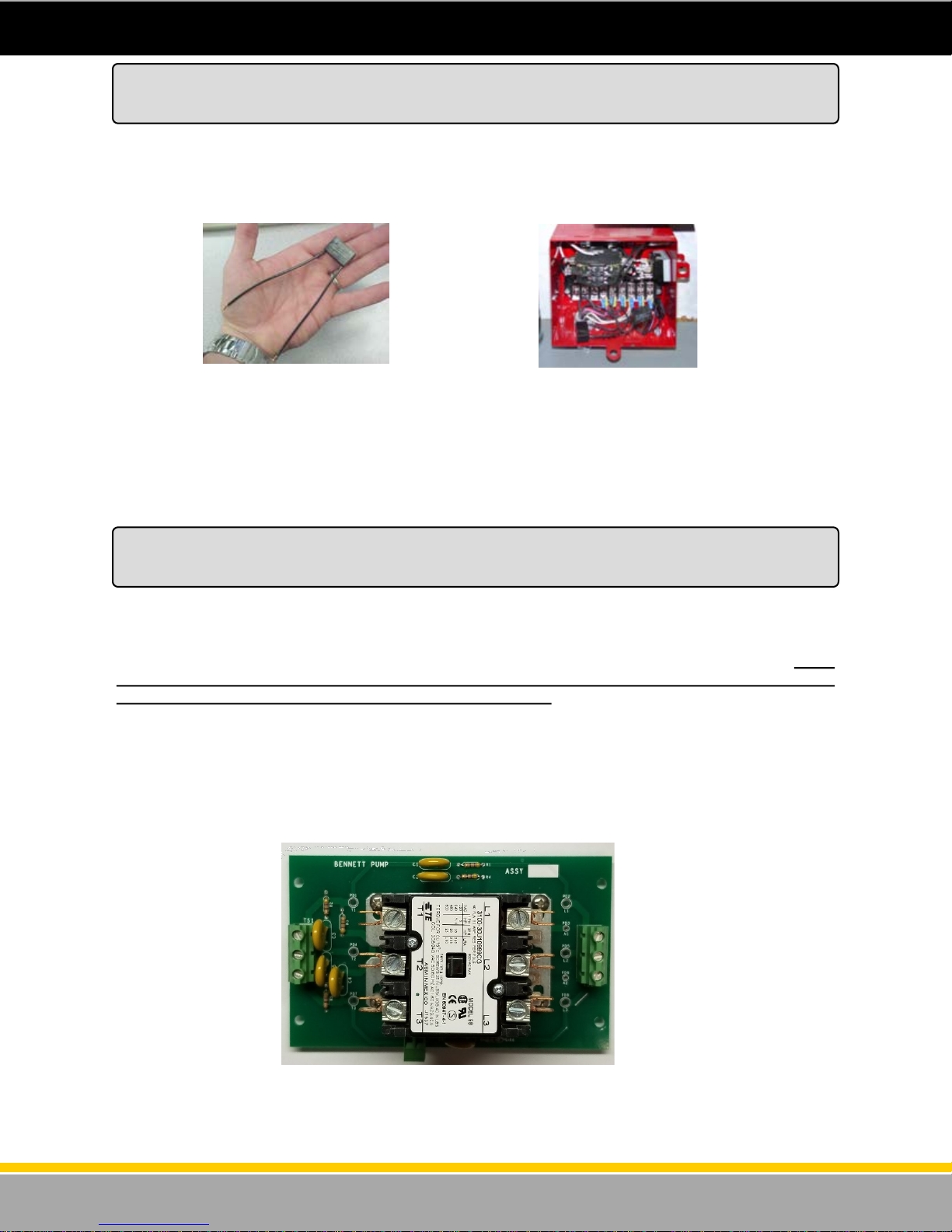
An RC Network is an electrical noise suppression device (see figure 37). It is used on AC power devices such as coils and across relay contacts (see figure 38). When AC voltage is applied to coils they are
converted to electromagnets. Coils are used to operate AC devices, such as solenoid dispensing valves
and AC power relays or contactors. W hen the AC power is removed from a coil, the electromagnetic
field collapses. This causes an AC voltage spike as high as 1500 VAC which can affect electronic sys-
tems.
Installing RC Networks
For Submerged Pump Systems
Figure 37 - An RC Network
Follow this procedure to protect dispenser and console operation:
Install an RC Network in the Control Relay Box across the following:
Across Coil to Neutral
Across M1 to L1
Across M2 to L2
Figure 38 - RC Networks
installed in control relay box.
Connecting Suction Pump Motor Power
for Suction (Self Contained) Pump Dispensers
Self-contained dispensers have the pump motor mounted in the lower hydraulic area. The power is
passed to the pump motor using the pump motor relay located on the CPU board in the electronic
enclosure. Use 14-gauge stranded THHN wire minimum for the suction pump motor wires for runs
under 50ft. 12Ga. for runs to 100ft, 10ga.for runs over 100ft, and 8 ga. for runs over 200 feet. Pump
motor power must be on a different phase leg than the dispenser power or system malfunction
will result and the Bennett Limited Warranty will be voided.
Termination of Field Wiring for Pump Motor Power of Self-Contained Dispensers
Note: Wire termination for 3-phase Motor Connections for 3000 series self-contained pumps with 210
or 531 electronics will be terminated directly to a 3-phase contactor relay or terminated to a
contactor board as shown in Figure 39.
Figure 39 - Contactor Board
46
120001 Rev K 1-19-18
Page 47
for Suction (Self Contained) Pump Dispensers cont...
Product “A” Suction Pump Motor Control (120VAC / 240VAC) - Connect the Blue 14ga. L1 - 120 or
240VAC (HOT) wire from the second motor power circuit breaker to terminal 4 of TS2 on the CPU
board. Connect the White 120VAC Neutral or the Black L2 240VAC wire from the motor power circuit
breaker directly to the pump motor neutral wire. Please refer to the Wiring Diagram located in the Wiring
Section of this manual or on the USB provided.
Product “B” Suction Pump Motor Power (120VAC / 240VAC) - Connect the Red 14ga. L1 - 120 or
240VAC (HOT) wire from the first motor power circuit breaker to terminal 4 of TS2 on the CPU board.
Connect the White 120VAC Neutral or the Black L2 240VAC wire from the motor power circuit breaker
directly to the pump motor neutral wire.
Note: Select the Submerged Pump control or Suction Pump control by setting a jumper wire on the
CPU. Make sure that there is NO jumper from P1 to P2 on the CPU board if controlling a
suction pump motor. This will be set at the factory.
3-Phase Suction Pump Motor Control (380VAC) - Connect the Brown 14ga. L1 - 380VAC (HOT) wire
from the first motor power circuit breaker directly to the 3-phase contactor relay or to TS2 terminal L1 on
the Contactor Board. Connect the Orange 380VAC (HOT) wire from the first motor power circuit breaker
to the 3-phase contactor relay or to TS2 terminal L2 on the Contactor Board. Connect the Yellow 14ga.
L3 - 380VAC (HOT) wire from the motor power circuit breaker directly to the 3-phase contactor relay or
to TS2 terminal L3 on the Contactor Board.
Note: Motors are 380VAC 50hz. Connections on factory supplied 3-phase contactor (relay).
Connecting Suction Pump Motor Power
Connecting the Communication Wires
For RS 485 Communication - For the RS-485 communication wires, use 18 gauge, twisted wires at
3 twists per foot. Refer to the RS-485 Wiring Diagram in the wiring section of the manual. Connect the
RS485 communication wires to TS1 on the CPU as follows:
RS 485 Positive (+) to TS1 Terminal 5 on the CPU Board.
RS485 Negative (-) to TS1 Terminal 7 on the CPU Board.
RS 485 Common (com) to TS1 Terminal 6 on the CPU Board.
For Bennett Current Loop Communication Protocol -
For these communication wires, use 18 gauge. Connect the current loop communication wires to TS1 on
the CPU as follows:
Current Loop Positive (+) to TS1 Terminal 7 on the CPU Board.
Current Loop Negative (-) to TS1 Terminal 5 on the CPU Board.
Note - Current Loop wiring CANNOT be
“daisy chained” so there should be two
separate current loop wires for each product /
hose position.
47
120001 Rev K 1-19-18
Page 48
Mechanical Mode - Mechanical Mode allows the 3000 series to imitate a mechanical dispenser and
interface to a mechanical pump console or control device. It also allows pulse output communication
with a tank gauge.
A separate mechanical (pulse output) interface board is required for the dispenser. There will be one
Pulse Output board for a single product (single hose or twin) dispenser. The board can output two
channels (Side 1 and Side 2) of pulse information for a console and also for a tank gauge, handle switch
output for pump “in use” signal, and an input for an “authorization” signal for each side of the dispenser
for a product. The mechanical interface board is mounted on the deck inside the electronics enclosure.
This mechanical interface board also communicates with the CPU/s boards.
Pulse Output - The pulse output allow s the 3000 mechani cal i nterface to send pulse inf ormation
to the console and the Tank Gauge. The system can be programmed to output pulse ratios from 1:1,
10:1, 100:1, and 1000:1. The control system connected to the dispenser must provide 5 - 12 volts DC for
the pulse output channel.
Refer to the Pulse Output Wiring Diagram in the back of this manual and the table on the next page to
see how to wire to the Pulse Output Board. The drawing shows how to wire directly to the pulse output
board OR, if there is an optional junction box installed, the correct wiring to the junction box. Also, the
table lists correct wiring to the Pulse Output Board OR to the optional junction box.
Handle Switch Signal— The handle switch signal can be used to signal the console that the pump is
“in use”. Some consoles require this signal and some do not. Refer to the Pulse Output Wiring Diagram
in the back of this manual and the table on the next page to see how to wire the handle switch signals.
Authorization Signal - A console or card/key system can send “authorization” to a fueling point (in the
form of a 110 volt signal) which allows the fueling point to reset at the beginning of the sale. Without this
signal, the dispenser will not reset when in the “Mechanical” mode. Refer to the Pulse Output Wiring
Diagram in the back of this manual and the table on the next page to see how to wire the Authorization
signals.
Tank Gauge Pulse Output Signals - The dispenser electronics Pulse Output Board can send pulse
information to the electronic Tank Gauge system so that it may reconcile dispensed product. The system
can be programmed to output pulse ratios from 1:1, 10:1, 100:1, and 1000:1. The Tank Gauge system
connected to the dispenser must provide 5 - 12 volts DC for the pulse output channel. Refer to the Pulse
Output Wiring Diagram in the back of this manual and the table on the next page to see how to wire the
Tank Gauge signals.
Connecting the Field Wires to the
Mechanical Interface Board
48
120001 Rev K 1-19-18
Page 49

Pulse Output Field Wiring Table
(Also refer to as the Pulse Output Wiring Diagram)
Name Color Wire
Tank Gauge Out Product A side 1
Tank Gauge Out Product A side 1
Tank Gauge Out Product A side 2
Tank Gauge Out Product A side 2
Pulse Output Product A side 1
Pulse Output Product A side 1
Pulse Output Product A side 2
Pulse Output Product A side 2
Handle Product A side 1
Handle Product A side 1
Handle Product A side 2
Handle Product A side 2
Authorization Product A side 1
Authorization Product A side 2
Neutral Product A side 1
Pulse Output Product B side 1
Pulse Output Product B side 1
Pulse Output Product B side 2
Pulse Output Product B side 2
Handle Product B side 1
Handle Product B side 1
Handle Product B side 2
Handle Product B side 2
Authorization Product B side 1
Authorization Product B side 2
Neutral Product B side 2
Tank Gauge Out Product B side 1
Tank Gauge Out Product B side 1
Tank Gauge Out Product B side 2
Tank Gauge Out Product B side 2
(+)
(-)
(+)
(-)
(+)
(-)
(+)
(-)
(+)
(-)
(+)
(-)
(+)
(-)
(+)
(-)
(+)
(+)
(+)
(-)
(+)
(-)
(+)
(-)
Size
Gray 1(+) 18 Ga. Flying Lead Gray Product A
Gray 1(-) 18 Ga. Flying Lead Gray Product A
Pink 1(+) 18 Ga. Flying Lead Pink Product A
Pink 1(-) 18 Ga. Flying Lead Pink Product A
Red (+) 18 Ga. Position 1 in J-Box TS1-1 Pulse Output Board Product A
Red (-) 18 Ga. Position 2 in J-Box TS1-2 Pulse Output Board Product A
Orange (+) 18 Ga. Position 3 in J-Box TS1-5 Pulse Output Board Product A
Orange (-) 18 Ga. Position 4 in J-Box TS1-6 Pulse Output Board Product A
Violet 1(+) 18 Ga. Position 5 in J-Box TS2-9 Pulse Output Board Product A
Violet 1(-) 18 Ga. Position 6 in J-Box TS2-10 Pulse Output Board Product A
Blue 1(+) 18 Ga. Position 7 in J-Box TS2-11 Pulse Output Board Product A
Blue 1(-) 18 Ga. Position 8 in J-Box TS2-12 Pulse Output Board Product A
Brown 1A 18 Ga. Position 9 in J-Box TS3 - 13 Pulse Output Board Product A
Brown 1B 18 Ga. Position 10 in J-Box TS3 -15 Pulse Output Board Product A
White (1) 18 Ga. Position 11 in J-Box TS3-14 & 16 Pulse Output Board Product A
Yellow (+) 18 Ga. Position 12 in J-Box TS1-1 Pulse Output Board Product B
Yellow (-) 18 Ga. Position 13 in J-Box TS1-2 Pulse Output Board Product B
Black (+) 18 Ga. Position 14 in J-Box TS1-5 Pulse Output Board Product B
Black (-) 18 Ga. Position 15 in J-Box TS1-6 Pulse Output Board Product B
Violet 2(+) 18 Ga. Position 16 in J-Box TS2-9 Pulse Output Board Product B
Violet 2(-) 18 Ga. Position 17 in J-Box TS2-10 Pulse Output Board Product B
Blue 2(+) 18 Ga. Position 18 in J-Box TS2-11 Pulse Output Board Product B
Blue 2(-) 18 Ga. Position 19 in J-Box TS2-12 Pulse Output Board Product B
Brown 2A 18 Ga. Position 20 in J-Box TS3-13 Pulse Output Board Product B
Brown 2B 18 Ga. Position 21 in J-Box TS3-15 Pulse Output Board Product B
White (2) 18 Ga. Position 22 in J-Box TS3-14 & 16 Pulse Output Board Product B
Gray 2(+) 18 Ga. Flying Lead Gray Product B
Gray 2(-) 18 Ga. Flying Lead Gray Product B
Pink 2(+) 18 Ga. Flying Lead Pink Product B
Pink 2(-) 18 Ga. Flying Lead Pink Product B
J-Box Connection
(Optional)
Marked 1(+)
Marked 1(-)
TS1 - 7 Pulse Output Board Product A
Marked 1(+)
TS1– 8 Pulse Output Board Product A
Marked 1(-)
TS1- 3 Pulse Output Board Product B
Marked 2(+)
Marked 2(-)
Marked 2 (+)
Marked 2 (-)
Board Connection
TS1-3 Pulse Output Board Product A
TS1-4 Pulse Output Board Product A
TS1-4 Pulse Output Board Product B
TS1-7 Pulse Output Board Product B
TS1-8 Pulse Output Board Product B
49
120001 Rev K 1-19-18
Page 50
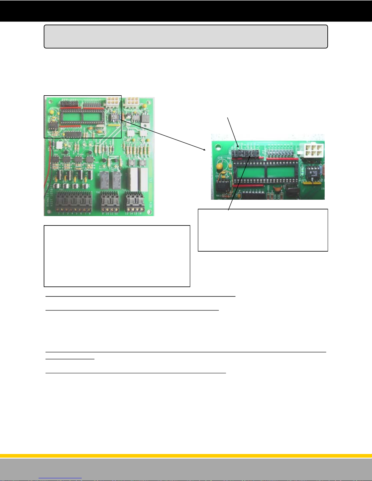
Setting the Jumpers on the Pulse Output Board
The Pulse Output board is ordered as an option with the Electronic 3000 Series. This board is where
the field wires connect the 3rd party Fleet System to the Pulse Output functions of the dispenser. This
board also has jumpers that need to be set to determine the Pulse Rate and the Pulse Width. Whatever
pulse rate is set will send the same pulse rate and width to both the Fleet System and the Tank Gauge
(if one is connected). This section describes how to set these jumpers. Refer to the Figures below:
JP1-1,2,3,4,and 5 are used to set the pulse rate and pulse width.
Figure 40 - Pulse Output Board Jumpers
Figure 40 - Pulse Output Board
This is the Pulse Output Board. It has the terminal
strips for the field wire connections along the bottom
of the board to communicate with the Fleet System
using a pump handle output signal, an authorize input signal and a pulse train signal. The Jumper
Header JP1 is at the top left of the board. These
jumpers must be set to determine the pulse rate and
the pulse width. See information below.
To set the Pulse Rate Output, set jumpers JP1-1 and JP1-2 as follows:
JP1-1 JP1-2 Pulses Per Gallon Pulses per Liter
OUT OUT 1000 100
IN OUT 100 10
OUT IN 10 1
IN IN 1 1/10TH
To set Pulse Width, set jumpers JP1-3, JP1-4, JP1-5 as follows (PULSE WIDTH’S ARE IN
MILLISECONDS):
JP1-3 JP1-4 JP1-5 Pulse Width Pulses Per Minute
OUT OUT OUT .5 ms 60000
IN OUT OUT 1 ms 30000
OUT IN OUT 2 ms 15000
IN IN OUT 4 ms 7500
OUT OUT IN 8 ms 3750
IN OUT IN 16 ms 1875
OUT IN IN 32 ms 9378
IN IN IN 64 ms 467
The top left of the Pulse Output board has a
jumper header called JP1. It has 8 jumper
positions. Set the Pulse Rate with the first two
jumpers and the Pulse Width with the 3rd, 4th
and 5th. See information below.
50
120001 Rev K 1-19-18
Page 51
Dispenser Startup and Checklist
DANGER: Fire, explosion, injury or death will occur if fuel vapors are present. Make sure there
are no vapors present before starting this procedure.
CAUTION: To prevent damage to the dispenser, follow the proper start-up procedures.
Before applying AC power to the dispenser, follow this procedure:
1. Unlock and open the upper and lower dispenser doors.
2. Check to make sure:
The boards and other components have not come loose from shipping. LCD display boards are
not cracked or damaged.
The cables are properly connected to the boards. There are no torn cables or stranded
harnesses.
Pulser and pump handle harnesses are connected properly to the CPU board.
3. Make sure the shut off valves are closed.
4. Turn off all submerged pump circuit breakers and all other circuit breakers to the dispenser.
Make sure the 12-gauge green ground wire is properly connected and measures 1 ohm (or less)
resistance to earth ground. This measurement should be taken between neutral and ground at the
dispenser. When taking this measurement make sure the ground and the neutral are disconnected at
the dispenser. This ensures that the resistance read is not across the electronics on the circuit board. If
the resistance reading is more than 1 ohm, the dispenser electronics may not operate properly and will
void the Bennett Limited Warranty.
Turn on 115 or 230 Volts AC dispenser power to the unit.
1. Use a voltmeter to verify 115 or 230 Volts AC only at Terminal 2 on TS2 of the CPU board. Terminal
1 of TS2 on the CPU board is Neutral. This AC circuit provides power to the electronic boards.
2. Make sure displays are normal and not garbled.
WARNING: Make sure all dispenser power circuits for REMOTES ONLY are on the same phase/
leg of the breaker panel or damage will result.
3. Turn the dispenser power off. Program the dispenser for Stand Alone operation by removing the
jumper from JP1 jumper 5. (Do not lose this jumper because it may be needed again later). Refer to
the previous section for jumper settings. Turn the dispenser power back on.
CHECK THE PUMP MOTOR CIRCUIT
WARNING: To prevent injury, make sure impact valves and submerged pump breakers are off.
1. Put the 1st Product’s pump handle in the ON position. The dispenser display will reset. Use a
voltmeter to verify 115 or 230 Volts AC on Terminal 3 on TS2. Use Terminal 1 as neutral.
2. Put the 1st Product pump handle in the OFF position.
3. Repeat this process for the remaining hose positions.
4. Turn on all handles for the same product and make sure the dispensers are operating properly.
Make sure all dispensers for each product are on the same phase of power. The dispensers should
not be on different phases of power.
5. Open and set the impact valves.
Remotes
51
120001 Rev K 1-19-18
Page 52
Dispenser Startup and Checklist
Self-Contained
WARNING: If the lower door on the pulley side of the unit is off, close the door and lock it to pre-
vent injury.
1. Verify that the motor voltage select switch on the self contained motor is in the proper position.
2. Turn on the 1st Product pump motor circuit breaker. With the pump handle OFF, use a voltmeter to
verify 115/230 Volts AC power for the self contained pump motor by measuring between (Hot) terminal 4 on TS2 of the CPU and (Neutral) terminal 1 of TS2 of the CPU board. Also, if this is a 230 volt
A.C. power circuit for the suction pump motor, check between terminal 4 of TS2 on the CPU board
and neutral of the pump motor. The pump motor has two wires coming into the dispenser head from
the motor. One lead connects to the dispenser electronics (factory connected) and the other lead is
for the installer to run the neutral return. If the motor is being operated off of 230 volts, this is the
other phase leg for the suction pump motor. The solid state relay for the suction pump motor is lo-
cated on the CPU board. The 1st Product pump motor should not be running at this time.
3. Turn off the 1st Product pump motor circuit breaker.
4. Repeat this test for the remaining hose positions.
All Dispensers
1. Turn off all circuit breakers.
2. Close and lock the lower doors and the upper doors.
3. Turn the circuit breaker for the system on.
4. Purge the air from the system.
5. Dispense a small amount of fuel from each hose to verify all positions are counting.
Proceed to the section for finishing the installation called “Potting Instructions”.
Then proceed to the section titled “How to Calibrate the SB-100 Meter” .
52
120001 Rev K 1-19-18
Page 53

Potting Instructions
1. Install field conduit dispenser per NFPA-70 along with any
state and local codes.
2. Pull field wiring allowing 72 inches of extra wire to reach upper
electrical enclosure.
3. Feed wire through conduit and into upper electrical enclosure
CAUTION: Do not damage wire while feeding through
conduit into the upper electrical enclosure.
4. Wrap some “CHICOX” fiber around wires and push into
conduit assembly to prevent potting from running down the
length of the conduit (see figure 40).
5. Using the wire separator provided, install one wire in each
hole until all wires are separated (see figure 41).
6. Push wire separator at least 3/4” into conduit.
7. Prepare potting compound according to directions.
NOTE: Use “CHICO A3” potting compound for sealing
fittings in hazardous locations.
8. Using a funnel, pour potting into conduit, be sure to get potting
in between each wire (see figure 41).
9. Let stand until firm.
10. Shorten field wiring to appropriate length when making
connections
11. Attach field wiring to terminal strip in upper electrical enclosure
according to the wiring diagram supplied for this dispenser
(see figure 42).
Figure 41 - Potting Instructions
Figure 42 - Wire Termination
53
120001 Rev K 1-19-18
Page 54
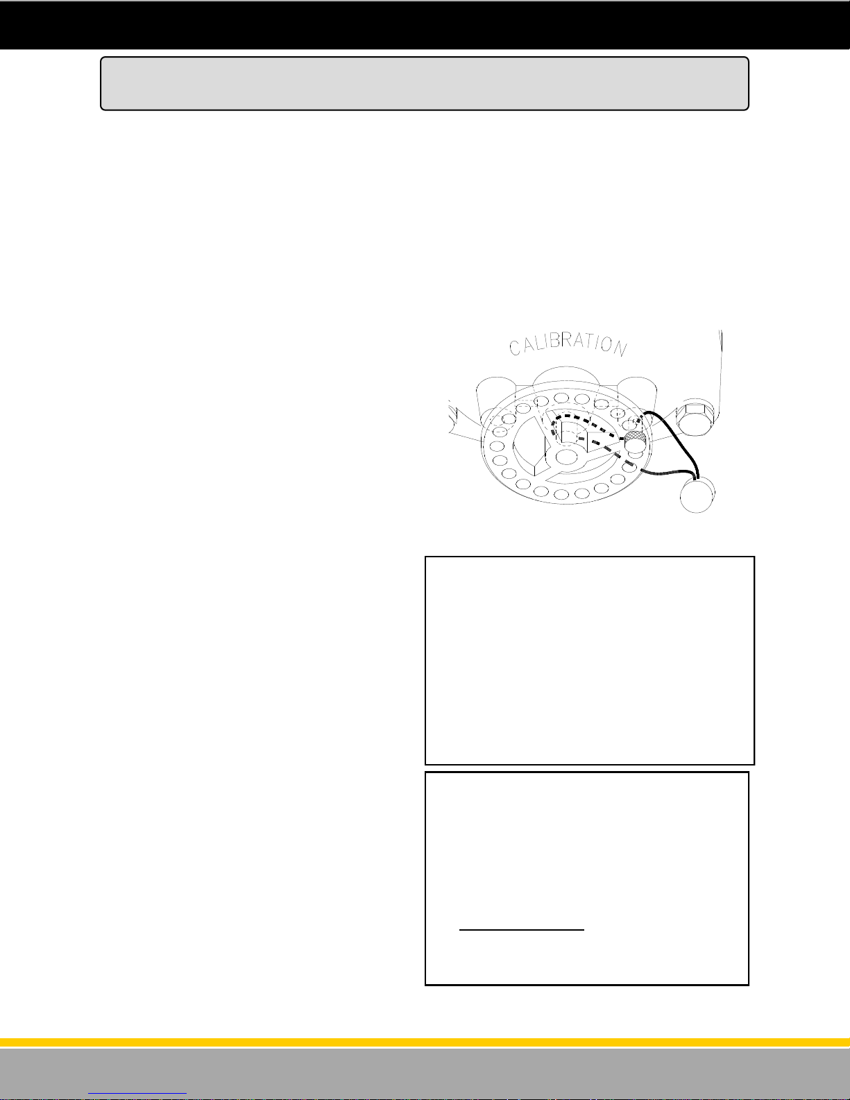
The Bennett SB-100 Meter is built to maintain accurate measurement under normal operating
conditions. The meter is a positive displacement device with rods and pistons, which require a break in
period. The meter is calibrated at the factory using a solvent for safety purposes, and must be
calibrated after it has been installed. We strongly suggest recalibration of the meter after a 90 day break
in period.
With the 3800 series electronic dispenser, mechanical calibration is optional. The standard 3700 is
calibrated electronically. This means that the meter in the dispenser may not be able to be calibrated
mechanically (it will not have a mechanical calibration wheel). If the meter on the dispenser does not
have the mechanical calibration wheel on it then use the electronic calibration option. Go to the next
section in this manual that explains how to perform an electronic calibration.
The dial adjusting cover has (+) and (-) arrows to
indicate the correct direction to rotate the dial to
either increase or decrease delivery.
The dial cover has two pin hubs, one to the left of
the shaft and one to the right. The seal pin may be
inserted in either hub (see figure 43). The smallest
adjustment (.6 cu. in.) occurs when the pin is pulled
from one side and inserted in the other side by
moving the dial the least amount or half a hole. A
1.2 cu. in. adjustment is made by pulling the pin
and turning the dial until the next adjacent hole
aligns with the same hub and reinserting the pin.
To calibrate the meter, follow this procedure:
1. Measure the actual delivery of the meter at fast
flow in an accurate test measure. Dispense a
minimum of 5 gallons (20 liters).
2. Cut and remove the existing seal wires and
remove the seal pin (see figure 42).
3. Turn the dial the necessary amount in the (+)
or (-) direction to increase or decrease the
quantity of fuel delivered.
4. Re-insert the seal pin in the desired pin hub.
5. Dispense 5 gallons (20 liters) of fuel to allow
the meter to adjust to the new settings. Do not
make any adjustments based on this delivery.
6. Make sure the meter is properly calibrated.
Dispense another 5 gallons (20 liters) of fuel
into an official test measure to check the
calibration.
How to Mechanically Calibrate the SB-100 Meter
(M-Cal Option)
Figure 43 - Calibration Wheel
Example 1
1. A fast flow test at 11 GPM shows a +3 cu. in.
reading in a five gallon test measure.
2. Remove the existing seal and pin and turn the
dial clockwise (-)five minimum adjustments (half
holes) and reinsert the pin.
3 cu. in. = 5 half holes (-)CW
.6 cu. in./adjustment
3. Test and reseal.
Example 2
1. A fast flow test at 11 GPM shows a -2 cu. in.
reading in a five gallon test measure.
2. Remove the existing seal and pin and turn the
dial counterclockwise (+) three minimum
adjustments (half holes) and reinsert the pin.
2 cu. in. = 3 half holes (+) CCW
.6 cu. in./adjustment
3. Test and reseal
54
120001 Rev K 1-19-18
Page 55

The basic calibration procedure assumes that the test can sight glass is graduated in units of cubic
inches or cubic centimeters (milliliters). If the sight glass is in test can percentage units, refer to the
optional calibration procedure in the next section.
1. Under normal dispenser operation, fill a test can to verify proper meter calibration. If the meter is
2. If the meter is out of calibration, write down the amount of the error from the test can sight glass. The
3. Plug in the Manager Keypad to the J6 connector on the CPU/Control Board. Break the seal on the
4. With the Manager Keypad enter the size of the test can and press the ENTER button. The test can
5. Enter the amount of the error recorded previously and press the ENTER button. At this point,
6. If another test can is filled, the error amount display appears as soon as the pump handle is turned
7. Move the calibration switch back to the operate position and seal it. Disconnect the Manager
The optional calibration procedure assumes that the test can sight glass is graduated in test can
percentage units rather than cubic inches or cubic centimeters (milliliters) as in the basic calibration
procedure. If the sight glass is in cubic inches or cubic centimeters, refer to the basic calibration
procedure in the previous section.
1. Under normal dispenser operation, fill a test can to verify proper meter calibration. If the meter is
2. If the meter is out of calibration, write down the amount of the error from the test can sight glass.
3. Plug in the Manager Keypad to the J6 connector on the CPU/Control Board. Break the seal on the
4. With the Manager Keypad enter the size of the test can and press the ENTER button. The test can
5. The default error amount display is for cubic inches or cubic centimeters. To bring up the percent
6. Enter the amount of the error recorded previously and press the ENTER button. At this point,
7. If another test can is filled, the error amount display appears as soon as the pump handle is turned
8. Move the calibration switch back to the operate position and seal it. Disconnect the Manager
How to Electronically Calibrate the SB-100 Meter
(E-Cal Option)
The Basic Calibration Procedure
properly calibrated, the procedure is finished.
error amount should be either cubic inches or cubic centimeters (milliliters).
electronic calibration switch and move the switch to the calibrate position. This brings up the test
can size display. This switch is located on the top of the CPU board.
size ranges from 0.1 to 999.9 volume units. When the test can size is entered, the error amount
display appears.
another test may be filled for calibration verification by turning on the pump handle. If another test
can is not desired, proceed to step 7.
off. If the meter is out of calibration, write down the amount of the error from the test can sight glass.
Go to step 5.
Keypad.
The Optional Calibration Procedure
properly calibrated, the procedure is finished.
The error amount should be a percentage of the test can’s volume.
electronic calibration switch and move the switch to the calibrate position. This brings up the test
can size display.
size ranges from 0.1 to 999.9 volume units. When the test can size is entered, the error amount
display appears.
error display, press the UP-ARROW button.
another test may be filled for calibration verification by turning on the pump handle. If another test
can is not desired, proceed to step 8.
off. If the meter is out of calibration, write down the amount of the error from the test can sight glass.
Go to step 6.
Keypad.
55
120001 Rev K 1-19-18
Page 56

How to Electronically Calibrate the SB-100 Meter (Cont’d)
(E-Cal Option)
The Direct Percent Entry Procedure
The direct percent entry procedure provides a way of zeroing or overwriting the electronic calibration
constant. This procedure is not accumulative. The basic and the optional calibration procedures
described previously are accumulative. The percent value entered in this procedure becomes the new
electronic calibration correction constant for the meter. This procedure requires no test can.
1. Break the seal on the electronic calibration switch and move the switch to the calibrate position.
This brings up the test can size display.
2. Press the UP-ARROW button to bring up the electronic calibration correction constant display.
3. Press the +/- button to bring up the percent error display.
4. Enter the percent error amount and press the ENTER button.
5. Move the calibration switch back to the operate position and seal it.
Viewing the Electronic Calibration Correction Constant
The electronic calibration correction constant may be viewed with the electronic calibration switch in
either position (calibrate or operate). If the switch is in the calibrate position, the correction constant can
be viewed from the test can display by pressing the UP-ARROW button. Pressing the UP-ARROW
button a second time returns to the test can display. If the switch is in the operate position, enter
manager’s mode followed by menu 27 to view the calibration constant.
56
120001 Rev K 1-19-18
Page 57
Footprint Dimensions and Wiring Diagrams
Find the appropriate footprint dimensional drawings and wiring diagrams for the Model of dispenser
being installed in the following section of this manual. Read and follow all directions and safety notices.
WARNING: RISK OF ELECTRICAL SHOCK – More than one disconnect switch may be required to de
-energize the device for serving.
Note - Dispenser electrical disconnect must comply with National Electrical Code, NFPA 70.
WARNING: All doors mu st be rep laced and locked when un it is in servi ce.
WARNING: EXPOSED B ELTS AND PULLEYS. Do not operate p ump with d oor remov ed except
when required for maintenance and then only by a Bennett Authorized Service Representative. Keep
clear of belts and pulleys.
57
120001 Rev K 1-19-18
Page 58

Footprint Dimensions and Wiring Diagrams
3000 SERIES ELECTRONIC DISPENSER FOOTPRINTS
Index of Dispenser Model Numbers ......................................................................................................................... 59
REMOTE MODELS
P1383 - LPS Sat elli te 1 Product 1 Hose or 2 Prod uct 2 Hose ...................................................................... 60
P1387s1 View 2 - 1 Product 1 Hose and 2 Product 2 Hose ............................................................................. 61
P1387s2 View 3 - 1 Product 2 Hose ................................................................................................................. 62
P1387s2 View 3 - 2 Product 4 Hose ................................................................................................................. 63
SELF-CONTAINED (SUCTION) MODELS
P1388s1 View 1 - All Models ............................................................................................................................ 64
BIG FUELER - SATELLITE MODELS
P1385s1 View 1 - Self Contained Big Fueler Master 1 Product 1 Hose and 2 Product 2 Hose ........................ 65
P1385s2 View 4 - Remote 2 Product 2 Hose or Satellite 1 Product 1 Hose ..................................................... 66
BIG FUELER - HIGH HOSE REMOTE MASTER MODELS
P1384s1 View 1 - 2 Product 2 Hose or 1 Product 1 Hose ................................................................................ 67
P1384s1 View 2 - 1 Product 2 Hose ................................................................................................................. 68
BIG FUELER - HIGH HOSE REMOTE COMBO MASTER MODELS
P1384s2 View 3 - Master 1 Product 1 Hose / Satellite 1 Product 1 Hose ........................................................ 69
P1384s2 View 4 - Master 2 Products 2 Hose / Satellite 2 Products 2 Hose .................................................... 70
BIG FUELER - LOW HOSE REMOTE MASTER MODELS
P1384s3 View 5 - Master 1 Product 1 Hose or 2 Product 2 Hose ................................................................... 69
P1384s3 View 6 - Master 1 Product 2 Hose ..................................................................................................... 70
BIG FUELER - LOW HOSE REMOTE COMBO MODELS
P1384s4 View 7 - Master 1 Product 1 Hose / Satellite 1 Product 1 Hose ........................................................ 73
WIRING DIAGRAMS
Signal Wiring for Master to Satellite Configuration ............................................................................................ 74
Pulse Output Wiring Diagram ............................................................................................................................ 75
Current Loop / RS485 Communication Remote Pumps with 210/531 Electronics Wiring Diagram ................... 78
Notes for Current Loop / RS485 Communication Remote Pumps with 210/531 Electronics Wiring Diagram ... 79
Self Contained Power Wiring Diagram AC Power & Motor Connections ........................................................... 80
Self Contained Power Wiring Diagram 3-Phase AC Power & Motor Connections ............................................ 81
Self Contained Power Wiring Diagram Big Fueler Self Contained Models AC Power & Motor Connections ... 82
58
120001 Rev K 1-19-18
Page 59

Index of 3000 Series Electronic Footprint Drawings
Note: Onl y elec tronic dispenser footp rints are i nclu ded in this man ual.
Base Model Any 3 Letters Suffix Numbers Drawing Number
Example: 3711 S N S -40 P1384s1 View 1
3711 -40 P1384s1 View 1
3711 -37 -38 P1384s3 View 5
3711 -17 -18 -19 -20 P1387s1 View 2
3711 -1 -2 -3 -4 P1388s1 View 1
3711 -41 -42 -44 P1385s1 View 1
3712 -49 -50 P1384s1 View 2
3712 -45 -46 -47 P1384s3 View 6
3712 -21 -22 -23 -24 -25 -26 P1387s2 View 3
3712 -5 -6 -7 -8 -9 -10 P1388s1 View 1
3722 -58 P1384s2 View 3
3722 -57 P1384s4 View 7
3722 -55 -56 P1384s1 View 1
3722 -51 -52 -53 P1384s3 View 5
3722 -27 -28 29 -30 -31 -32 P1387s1 View 2
3722 -11 -12 -13 -14 -15 -16 P1388s1 View 1
3724 -35 -36 P1387s2 View 4
3724 -33 -34 P1388s1 View 1
3744 -56.1 P1384s2 View 4
3811 -59 -60 P1385s2 View 4
3811 -40 P1384s1 View 1
3811 -37 -38 P1384s3 View 5
3811 -17 -18 -19 -20 P1387s1 View 2
3811 -1 -2 -3 -4 P1388s1 View 1
3812 -49 -50 P1384s1 View 2
3812 -45 -46 -47 P1384s3 View 6
3812 -21 -22 -23 -24 -25 -26 P1387s2 View 3
3812 -5 -6 -7 -8 -9 10 P1388s1 View 1
3822 -61 -62 -63 -64 P1385s2 View 4
3822 -58 P1384s2 View 3
3822 -57 P1384s4 View 7
3822 -55 -56 P1384s1 View 1
3822 -51 -52 -53 P1384s3 View 5
3822 -27 -28 -29 -30 -31 -32 P1387s1 View 2
3822 -11 -12 -13 -14 -15 -16 P1388s1 View 1
3824 -35 -36 P1387s2 View 4
3824 -33 -34 P1388s1 View 1
3844 -56.1 P1384s2 View 4
LPS-40-1-65 - - P1383
LPS-40-2-65 - - P1383
LPS-60-1-65 - - P1383
LPS-60-2-65 - - P1383
59
120001 Rev K 1-19-18
Page 60

Remote 1 Product 1 Hose or 2 Product 2 Hose
Note: Drawing schematic P1383 (Part Number 110931) can be found on the USB provided.
LPS Satellite
60
120001 Rev K 1-19-18
Page 61

Remote 1 Product 1 Hose & 2 Product 2 Hose Models
Note: Drawing schematic P1387s1 View 2 (Part Number110223 ) can be found on the USB provided.
3000 Series Footprint Drawings
61
120001 Rev K 1-19-18
Page 62

Note: Drawing schematic P1387s2 View 3 (Part Number 110223 ) can be found on the USB provided.
3000 Series Footprint Drawings
Remote 1 Product 2 Hose Models
62
120001 Rev K 1-19-18
Page 63

Note: Drawing schematic P1387s2 View 4 (Part Number110223) can be found on the USB provided.
3000 Series Footprint Drawings
Remote 2 Product 4 Hose Models
63
120001 Rev K 1-19-18
Page 64

Note: Drawing schematic P1388s1 View 1 (Part Number110224) can be found on the USB provided.
3000 Series Footprint Drawings
Self-Contained (Suction) All Models
64
120001 Rev K 1-19-18
Page 65
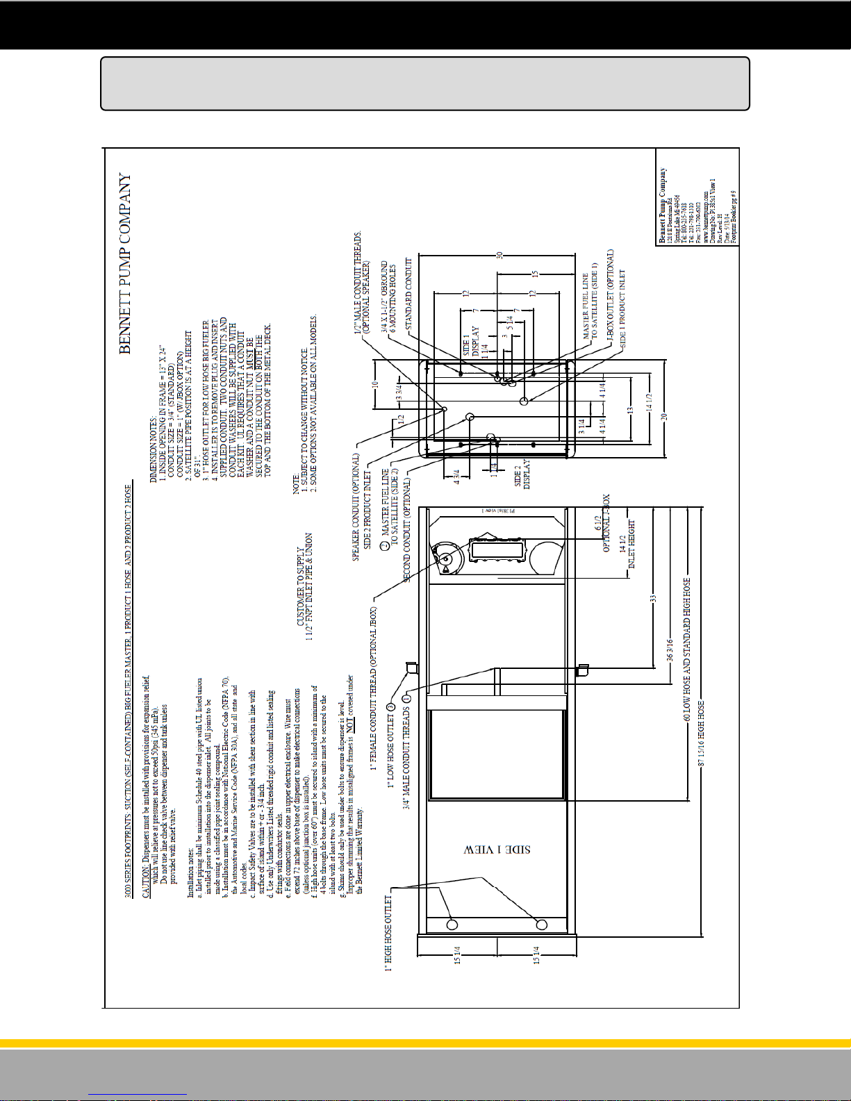
Big Fueler - Self Contained Master 1 Product 1 Hose and 2 Product 2 Hose
Note: Drawing schematic P1385s1 View 1 (Part Number 110226) can be found on the USB provided.
3000 Series Footprint Drawings
65
120001 Rev K 1-19-18
Page 66

Big Fueler Satellite - Remote 2 Product 2 Hose or Satellite 1 Product 1 Hose
Note: Drawing schematic P1385s2 View 4 (Part Number 110226) can be found on the USB provided.
3000 Series Footprint Drawings
66
120001 Rev K 1-19-18
Page 67

Big Fueler - High Hose Remote Master Models 2 Product 2 Hose or 1 Product 1 Hose
Note: Drawing schematic P1384s1 View 1(Part Number 110227 ) can be found on the USB provided.
3000 Series Footprint Drawings
67
120001 Rev K 1-19-18
Page 68

Big Fueler - High Hose Remote Master Models 1 Product 2 Hose
Note: Drawing schematic P1384s1 View 2 (Part Number110227) can be found on the USB provided.
3000 Series Footprint Drawings
68
120001 Rev K 1-19-18
Page 69
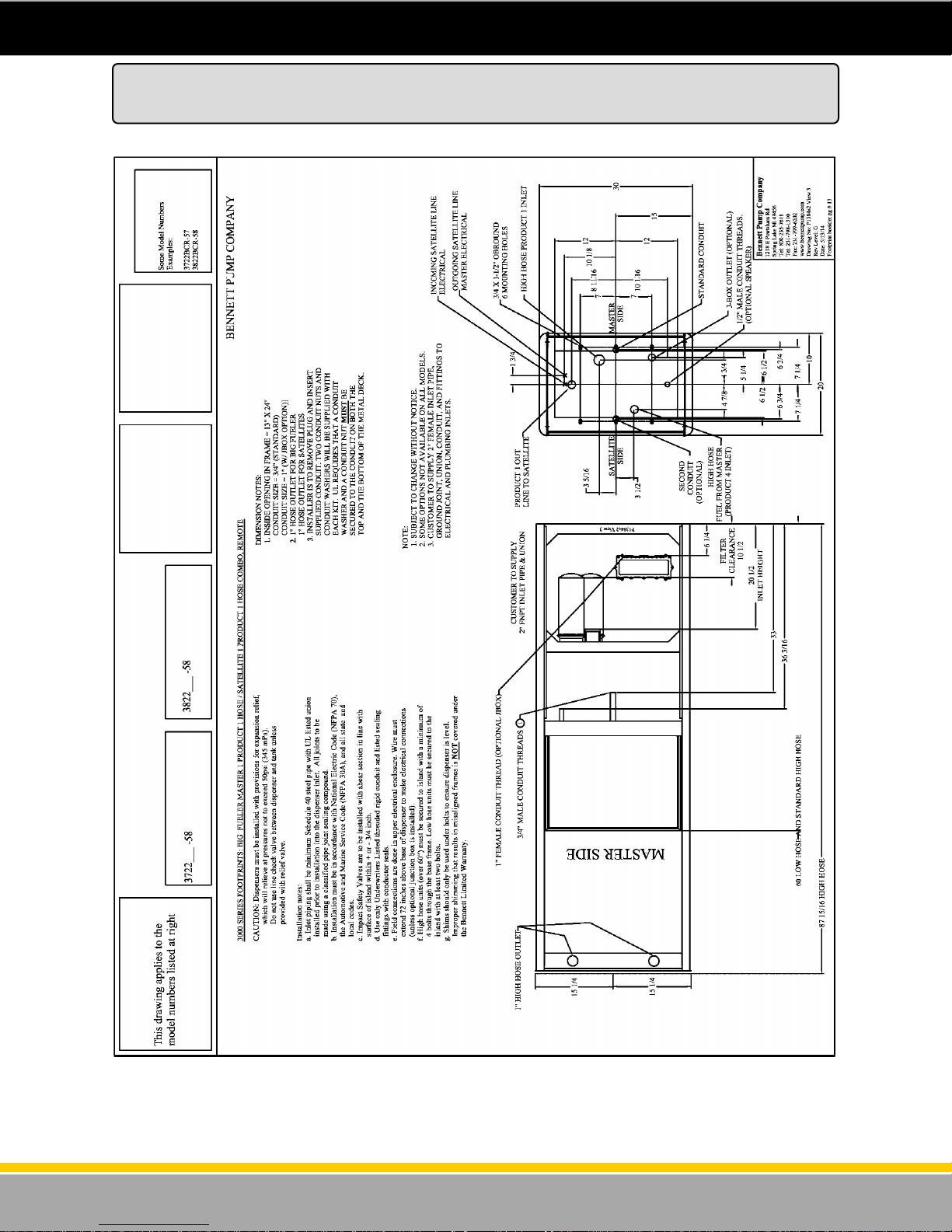
Big Fueler - High Hose Remote Combo Master Models 1 Product 1 Hose / Satellite 1 Product 1 Hose
Note: Drawing schematic P1384s2 View 3 (Part Number110227) can be found on the USB provided.
3000 Series Footprint Drawings
69
120001 Rev K 1-19-18
Page 70

Big Fueler - High Hose Remote Combo Master Models 2 Products 2 Hose / Satellite 2 Products 2 Hose
Note: Drawing schematic P1384s2 View 4 (Part Number 110227) can be found on the USB provided.
3000 Series Footprint Drawings
70
120001 Rev K 1-19-18
Page 71

Big Fueler - Low Hose Remote Master Models 1 Product 1 Hose or 2 Product 2 Hose
Note: Drawing schematic P1384s3 View 5 (Part Number 110227) can be found on the USB provided.
3000 Series Footprint Drawings
71
120001 Rev K 1-19-18
Page 72

Big Fueler - Low Hose Remote Master Models 1 Product 2 Hose
Note: Drawing schematic P1384s3 View 6 (Part Number 110227) can be found on the USB provided.
3000 Series Footprint Drawings
72
120001 Rev K 1-19-18
Page 73

Big Fueler - Low Hose Remote Combo Models Master 1 Product 1 Hose / Satellite 1 Product 1 Hose
Note: Drawing schematic P1384s4 View 7 (Part Number 110227) can be found on the USB provided.
3000 Series Footprint Drawings
73
120001 Rev K 1-19-18
Page 74
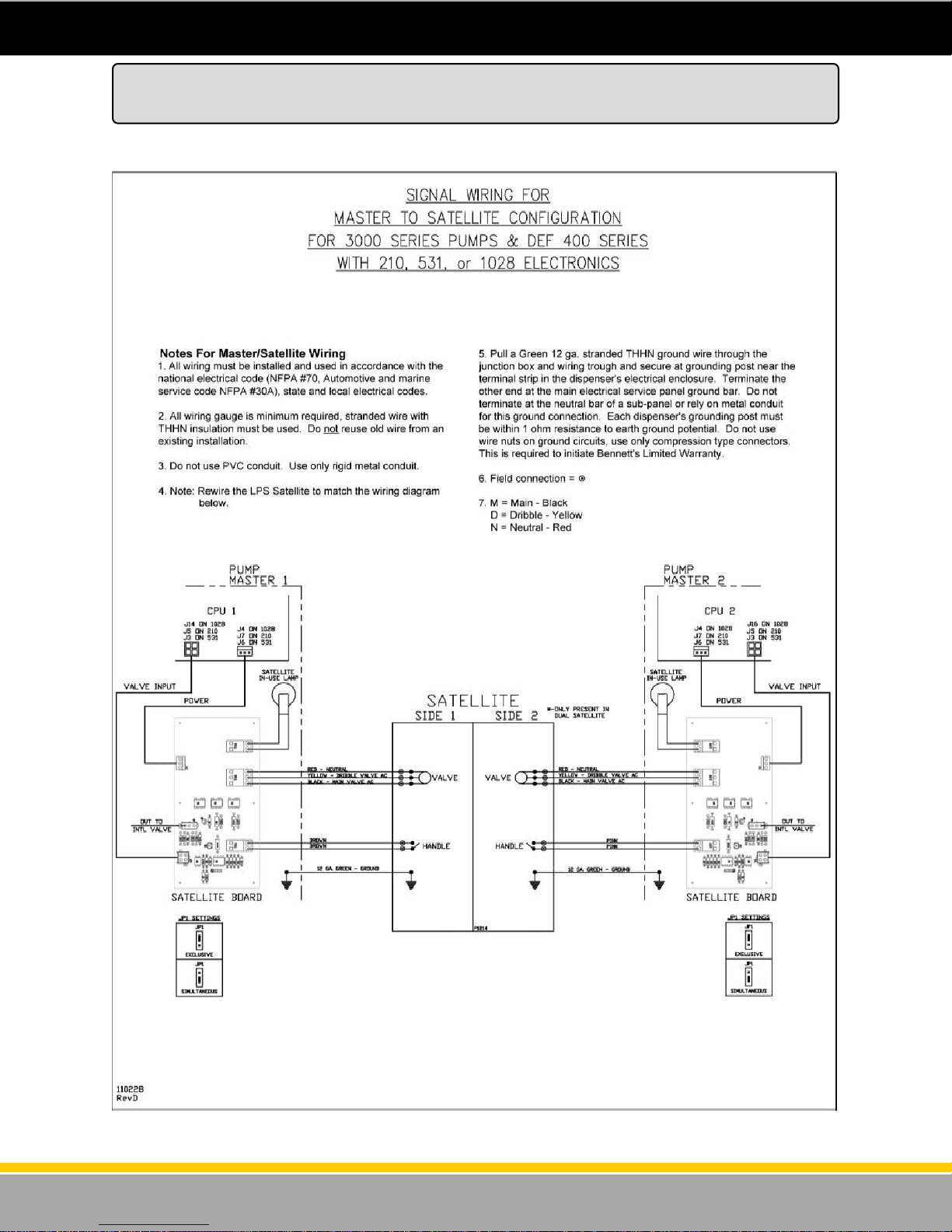
Note: Drawing schematic P1214 (Part Number 110228) can be found on the USB provided.
Signal Wiring for Master to Satellite Configuration
For 3000 Series Pumps & DEF 400 Series with 210, 531 or 1028 Electronics
74
120001 Rev K 1-19-18
Page 75

Pulse Output Wiring Diagram
Note: Drawing schematic P2072 can be found on the USB provided.
Close up on next page.
75
Drawing: P2072
Rev Level: B
Date: 01/13/09
120001 Rev K 1-19-18
Page 76

Pulse Output Wiring Diagram
Close up of drawing P2072 from previous page.
76
Drawing: P2072
Rev Level: B
Date: 01/13/09
120001 Rev K 1-19-18
Page 77
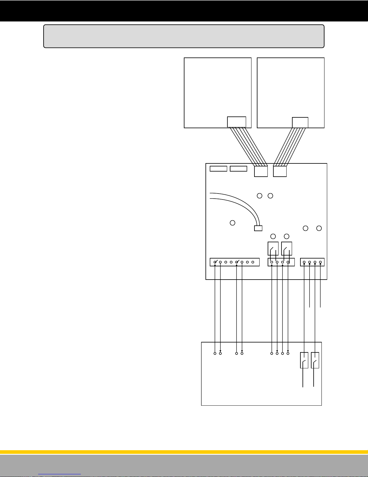
Pulse Output Board (Optional)
Notes to Installer: System Operation -
If the dispenser was ordered with the “Pulse
Output” function, one or two Pulse Output Boards
will be installed in the dispenser. One P.O.B.
(Pulse Output Board) can communicate with 2 CPU
boards.
The pulse output board is field wired to the 3rd
party Fleet Control System as shown in figure 44.
The P.O.B. is mounted horizontally on top of the
Barrier Circuit (cover) inside the head of the
dispenser.
Pulse output - The dispenser emulates a
mechanical reed switch pulser. Pulse rates of 1:1,
10:1, 100:1 and 1000:1 are available. When wiring
the pulse channels to the 3rd party system, the
fleet system must be set up for a DC voltage. It
must provide +5 to +12 vdc for the pulse circuit.
Voltage is not provided by the dispenser pulse
output board. TS1 provides 4 pulse output
channels (2 pulse outputs to the 3rd party fleet
system and two channels to an electronic tank
gauge). All 4 of these circuits are identical.
Handle Circuit - The handle signal on the P.O.B.
is used to signal the Fleet System that the pump is
“In Use” The P.O.B. uses a dry contact (normally
open) relay type of circuit. Run two wires from the
Fleet System to TS2. When the dispenser handle is
lifted this relay will close. This should signal the
Fleet System that the pump is “In Use”. The handle
signal can be an A.C. voltage or D.C. voltage. This
drawing shows a D.C. voltage as an example.
Authorization Signal - The dispenser P.O.B.
requires an authorization signal from the Fleet
System to start a sale. Without this authorization
signal, the pump will never reset and the sale will
not begin. The Fleet System sends the
authorization signal in the form of 120 volt A.C.
signal to TS3 as shown in the diagram to the right.
When the P.O.B. receives the authorization signal
and the handle is lifted, and the dispenser is
programmed properly, the sale should begin.
Wiring to the Fleet System - Refer to the CD-
ROM provided with the dispenser. Bennett
provides various interface diagrams to many of the
popular fleet card systems. Always consult with the
manufacturer and read all product manuals for
additional information on installing the 3rd party
card system. Call Bennett Technical Support for
assistance at 1-800-423-6638.
CPU
Product 1
J8
J1 J2
JP1 JP2
Red
Black
TEST LED
D 2
JP5 JP6 JP8 JP7
TS1 TS2 TS3
Pulse Output Side 1 (+)
+12 vdc
Note 1 - The handle signal can be an A.C. voltage or a
D.C. voltage. This board only provides a switch relay.
Pulse Output Side 2 (+)
Pulse Output Side 1 (-)
(Com)
+12 vdc
D 9 D 10
Test Cable
Pulse Output Side 2 (-)
(Com)
CPU
Product 2
D 4 D 7
(-) (+) (-) (+)
(Com)
+12 vdc or 120 vac Handle Side 1
+12 vdc or 120 vac Handle Side 2
J8
Pulse Output
Board
D 3 D 6
Neutral
Authorization Side 2 (120 v)
Authorization Side 1 (120 v)
(Com)
120 volt
120 volt
Neutral
77
Figure 44 - Pulse Output Diagram
120001 Rev K 1-19-18
Page 78

Remote Pumps with 210/531 Electronics Wiring Diagram
Note: Drawing schematic P2028 (Part Number 113075) can be found on the USB provided.
Current Loop / RS485 Communication
78
120001 Rev K 1-19-18
Page 79

Note: Drawing schematic P2028 (Part Number 113075) can be found on the USB provided.
Notes for Current Loop / RS485 Communication
Remote Power Wiring Diagram
79
120001 Rev K 1-19-18
Page 80
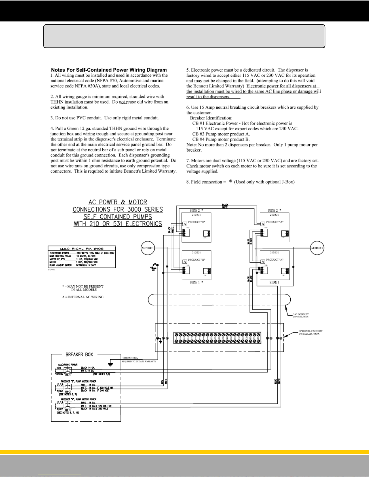
Note: Drawing schematic P1388s1 View 3 (Part Number 110224) can be found on the USB provided.
Self Contained Power Wiring Diagram
AC Power & Motor Connections for 3000 Series
80
Drawing: P1388s2
Rev Level: G
Date: 05.13.2014
120001 Rev K 1-19-18
Page 81
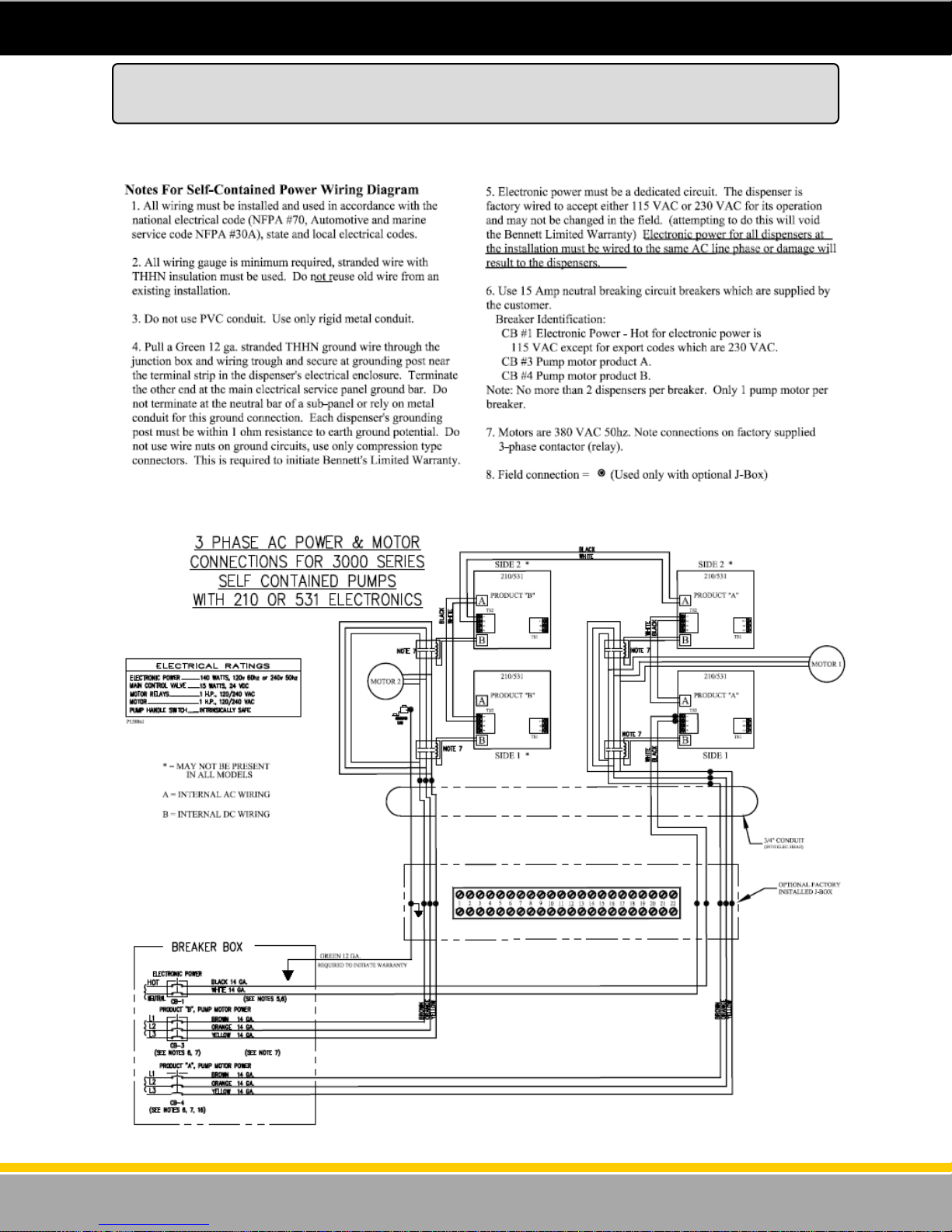
Note: Drawing schematic P1388s1 View 4 (Part Number 110224) can be found on the USB provided.
Self Contained Power Wiring Diagram
3-Phase AC Power & Motor Connections for 3000 Series
81
Drawing: P1388s2
Rev Level: G
Date: 05.14.2014
120001 Rev K 1-19-18
Page 82
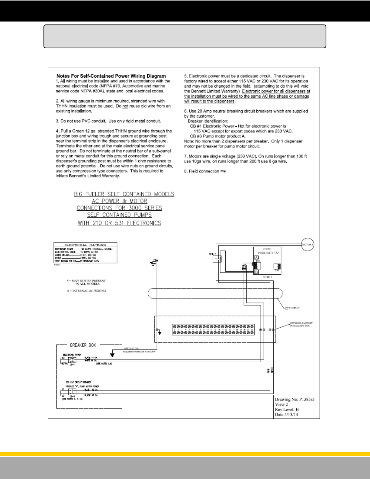
Big Fueler Self Contained Models AC Power & Motor Connections for 3K Series
Note: Drawing schematic P1385s3 View 2 (Part Number 110226) can be found on the USB provided.
Self Contained Power Wiring Diagram
82
120001 Rev K 1-19-18
Page 83

Bennett Pump Company
1218 E. Pontaluna Road
Spring Lake MI 49456
Fax: 231-799-6202
Bennett Pump Company
Site Audit Report
This form must be filled out and sent in to
Bennett to establish the equipment warranty.
3000 Series Electronic Dispensers.
108421
Date of Audit
_________________
Date of Installation
_________________
Model of Dispensers and Serial Numbers
Site Information:
Site Phone Number
Site Name
Site Address
City State Zip
Owned by
Equipment Purchase Date Date
Dispenser mode being used - Stand Alone Current Loop Pulse Output RS-485
Type of Interface Box being used if dispensers are connected to POS?
Third party interface system being used (Brand and Model)?
Yes No
If connected to a point of sale, Is the maximum distance between the dispensers and the Interface Box
less than 500 feet (150m)?
Are the field wires in metal conduit only?
Is there a conduit dedicated for each dispenser?
Are the dispenser field wires Oil and Gas resistant, color coded, THHN, copper stranded?
Are the dispenser field wires continuous with no splices?
Is the resistance measurement between Ground and Neutral at the dispenser less than one(1)ohm?
Measurement ______ ohm (Attach photo(s) if possible showing this measurement)
Checklist
Are there no more than 2 dispensers on one breaker (maximum)?
Are the dispensers on dedicated breakers and NOT sharing power with any other equipment (Sub
Pumps, pump motors, air conditioners, coolers etc..)?
Do the supply tanks have fuel?
If it is a suction system, are all suction components installed per Bennett specifications?
Are the Interface boxes within 100 feet (30m) of the Point of Sale? (If Applicable).
Is the vapor seal on field wires in the dispenser head installed?
Is the dispenser mechanically mounted to the island using securing bolts and shimmed for squareness?
Is there an emergency cutoff shear valve mounted on each product inlet on remote dispensers?
Is/Are there satellite dispensers installed?
Are all of the dispensers on the same phase of power?
Is an approved emergency stop relay installed and working properly for the fuel court area?
If this is a remote dispenser, are there RC Networks on the subpump relays?
Have the meter calibrations been verified?
Was the Bennett Warranty statement reviewed with the station Manager / Owner?
Name of Owner / Manager? _________________________________________
Were all Bennett installation instructions in the Installation Manual followed? If not, please list on the
next page.
83
120001 Rev K 1-19-18
Page 84

Exceptions to Bennett Installation Instructions / Additional Comments___________________
_______________________________________________________________________________
_______________________________________________________________________________
_______________________________________________________________________________
_______________________________________________________________________________
_______________________________________________________________________________
_______________________________________________________________________________
_______________________________________________________________________________
_______________________________________________________________________________
_______________________________________________________________________________
_______________________________________________________________________________
_______________________________________________________________________________
_______________________________________________________________________________
_______________________________________________________________________________
_______________________________________________________________________________
_______________________________________________________________________________
_______________________________________________________________________________
_______________________________________________________________________________
_______________________________________________________________________________
_______________________________________________________________________________
_______________________________________________________________________________
_______________________________________________________________________________
_______________________________________________________________________________
_______________________________________________________________________________
_______________________________________________________________________________
_______________________________________________________________________________
_______________________________________________________________________________
Tech Name ____________________________
Tech Email ______________________________
Certification Number_________________________
Tech phone ___________________________
Company ______________________________
Address __________________________________
Tech Signature ____________________________
Audited by:
84
120001 Rev K 1-19-18
Page 85

PCI SSC - Legal Terms and Conditions
PCI SSC’s approval only applies to PEDs that are identical to the PED tested by a PCI Security
Standards Council recognized laboratory. If any aspect of the PED is different from that which was test-
ed by the laboratory - even if the PED conforms to the basic product description contained the letter,
then the PED model should not be considered approved, nor promoted as approved. For example, if a
PED contains firmware, software, or physical construction that has the same name or model number as
those tested by the laboratory, but in fact are not identical to those PED samples tested by the laborato-
ry, then the PED should not be considered or promoted as approved.
No vendor or other third party may refer to a PED as “PCI Approved” nor otherwise state or imply that
PCI SSC has, in whole or part, approved any aspect of a vendor or its PEDs, except to the extent and
subject to the terms and restrictions expressly set forth in a written agreement with PCI SSC, or in an
approval letter. All other references to PCI SSC’s approval are strictly and actively prohibited by PCI
SSC.
When granted, an approval is provided by PCI SSC to ensure certain security and operational
characteristics important to the achievement of PCI SSC’s goals, but the approval does not under any
circumstances include any endorsement or warranty regarding the functionality, quality, or performance
of any particular product or service. PCI SSC does not warranty any products or services provided by
third parties. Approval does not, under any circumstances, include or imply any product warranties from
PCI SSC, including, without limitation, any implied warranties of merchantability, fitness for purpose or
noninfringement, all of which are expressly disclaimed by PCI SSC. All rights and remedies regarding
products and services, which have received an approval, shall be provided by the party providing such
products or services, and not by PCI SSC or the payment brand participates.
85
120001 Rev K 1-19-18
Page 86

Bennett Limited Warranty for Products Installed in the United States - 3000 Retail & Commercial
Bennett Pump Company guarantees new Service Station Equipment manufactured by Bennett against defects in material or workmanship
during the warranty period in accordance with the provisions stated below:
The Site Audit Report issued with all equipment must be completed and returned at time of installation to Bennett Pump Company, Spring Lake, MI to
initiate warranty.
Warranty service must be performed by the nearest Bennett Authorized Service Representative qualified to perform service on the defective equip-
ment. Only Authorized and Certified Service Representatives are allowed to perform warranty service. Use of service personnel other than quali-
fied Bennett Service Representatives without prior approval by Bennett Pump Company will void payment of any warranty claims.
Labor and travel costs incurred while servicing Bennett equipment will be paid at previously contracted rates subject to published standard repair time
allowances to qualified Bennett Service Representatives with travel cost limited to 200 miles. Travel cost shall be limited to 4 hours round trip.
Bennett equipment has been installed according to the manufacturer’s instructions and diagrams. Deviations will void this warranty.
During the warranty period, Bennett Pump Company will, at its option, repair or replace defective parts returned to its facto ry, transportation charges
prepaid.
The manufacturer reserves the right to make changes in the design or to make additions at any time.
Dispensers – 3000 Series Retail & Commercial Self Contained and Remote
Warranty on parts, labor, and travel is 12 months from date of installation or 18 months from date of Bennett’s original invoice, whichever comes first.
Warranty excludes nozzles, hoses and fittings, hose retractor, hose reels, filters, belt adjustments, paper jams, light bulbs, or any leaks after the installation start-up and audit.
Minor adjustments such as meter calibration, pulser adjustments, and handle switch adjustments, customer specified items manufactured by others, and customer requested
reprogramming of equipment are not covered by warranty.
Field Retrofit Card Readers, Payment Modules, Cash Acceptors, and all other field retrofit Accessories
The field retrofit assembly is warranted for parts only for 12 months from date of installation or 18 months from date of original invoice, whichever comes first, except the
receipt printer and driver board which is warranted for parts for ninety (90) days from the date of installation or 180 days from original invoice, whichever comes first.
Consumable Items such as receipt paper are not warranted. The use of receipt paper not specified by Bennett will void the printer assembly warranty.
Model 515 Pump Controller, 621 Module, Fan Out Boxes
Warranty on parts, labor and travel is 12 months from the date of installation or 18 months from the date of original invoice, whichever comes first.
Software
Bennett Pump Company warrants Bennett products and software packages, whose operation is controlled by Bennett designed and developed software, shall be free of
material defects and conform to current Bennett specifications for a period of ninety (90) days from the date of original invoice. Bennett shall use its best effort to correct such
defects and to supply to purchaser at Bennett’s expense, a corrected version within a reasonable time after purchaser notifies Bennett in writing of any defects and provides
the programs and instructions required to reproduce the claimed defect.
Warranty does not cover any modification to the program, the Bennett product, and/or connection to unapproved equipment made by any person or any defect caused by
such modifications/connections.
Upgrade Kits
Bennett offers kits which are installed as an option to enhance operating features of an existing Bennett product are warranted for parts only for ninety (90) days from date of
installation or 12 months from date of original invoice, whichever comes first. Upgrade Kit warranty applies to kit components only. Warranty status of the remainder of the
product remains unchanged.
Spare Parts
For equipment under warranty: The warranty period for all spare parts replaced is the remainder of the original warranty. Spare Parts are warranted for th e value of the parts
only (no labor, mileage, or other charges).
For equipment not under warranty: The warranty period is 90 days from the date of invoice to the end user, or 12 months from the date of original invoice, whichever comes
first. Spare Parts are warranted for the value of the parts only (no labor, mileage, or other charges).
General Exclusions
1.Warranty does not apply to any product which has not been installed to our published recommendations or has been altered, sub jected to unusual
physical or electrical stress, an Act of God, damaged by accident, tampered with, or subjected to misuse or abuse including s ubstituting parts or
accessories from other manufacturers without the written consent of Bennett Pump Company. The above warranties shall not exis t if the original
identification marks have been removed or altered.
2.Bennett makes no warranty with respect to the Bennett equipment or Bennett’s performance of services under this agreement, express or implied, and
Bennett hereby disclaims the implied warranties of merchantability and fitness for a particular purpose.
3.In no event shall Bennett be liable for any loss of profits, loss of use, interruption of business or indirect, special, incidental or consequential damages of any kind in connection with or arising out of the furnishing, performance, use or failure of the Bennett equipment, software or services acquired from Bennett, the distributor or the user, whether alleged as a breach of contract or tortuous conduct, including negligence. Bennett’s liability
hereunder for damages shall not, in any event, exceed the amounts paid by the buyer to Bennett for equipment, software or services as to which
the claim arose.
4.No action arising out of any claimed breach of the Warranty Agreement or transaction under this Warranty Agreement may be bro ught by either party
more than two (2) years after the cause of action has accrued.
5.Use of non-Bennett replacement parts, unless specified by Bennett, will void the equipment warranty.
6.This warranty only applies to Bennett equipment installed in the United States of America and is non-transferable.
7.Failure to pay the Bennett invoice within stated invoice terms, covering the respective Bennett equipment purchased under this limited warranty may,
at Bennett’s discretion, void this limited product warranty.
THE FOREGOING WARRANTIES ARE IN LIEU OF ALL OTHER WARRANTIES EXPRESSED OR IMPLIED INCLUDING,
WITHOUT LIMITATION, THE WARRANTY OF MERCHANTABILITY AND FITNESS FOR A PARTICULAR PURPOSE.
BENNETT PUMP COMPANY
1218 E. Pontaluna Road
Spring Lake, MI 49456
Tel: 231-798-1310
Fax: 231-799-6202
Form 1-1010-2 Rev D 6-29-17
Part# 135249
86
120001 Rev K 1-19-18
Page 87

Bennett International Limited Warranty for Dispensers and Pumps
Bennett Pump Company guarantees new Service Station Equipment manufactured by Bennett against defects in material or workmanship
during the warranty period in accordance with the provisions stated below:
The Site Audit Report issued with all equipment must be completed and returned at time of installation to Bennett Pump Company, Spring Lake, MI to
initiate warranty.
Warranty service must be performed by the nearest Bennett Authorized Service Representative qualified to perform service on the defective equip-
ment. Only Authorized and Certified Service Representatives are allowed to perform warranty service. Use of service personnel other than quali-
fied Bennett Service Representatives without prior approval by Bennett Pump Company will void payment of any warranty claims.
Labor and travel costs incurred while servicing Bennett equipment is not covered under this limited warranty.
Bennett equipment has been installed according to the manufacturer’s instructions and diagrams. Deviations will void this warranty.
During the warranty period, Bennett Pump Company will, at its option, repair or replace defective parts returned to its facto ry, transportation charges
prepaid.
The manufacturer reserves the right to make changes in the design or to make additions at any time.
Dispensers (Remote and Self-contained styles) (excluding Natural Gas, Hydrogen and Hydraulic-less Dispensers)
The Warranty will cover repair or replacement, at Bennett’s option, of the parts only that are deemed to be defective in material or workmanship at Bennett’s discretion, for a
period of 12 months from date of installation or 18 months from date of Bennett’s original invoice, whichever comes first.
Warranty excludes nozzles, hoses and fittings, hose retractor, filters, belt adjustments, paper jams, light bulbs, or any lea ks after the installation start-up and audit. Minor
adjustments such as meter calibration, pulser adjustments, and handle switch adjustments, customer specified items manufactured by others, and customer requested reprogramming of equipment are not covered by warranty.
Field Retrofit Card Readers, Payment Modules, Cash Acceptors, and all other field retrofit Accessories
The field retrofit assembly is warranted for parts only for 12 months from date of installation or 18 months from date of original invoice, whichever comes first, except the
receipt printer and driver board which is warranted for parts for ninety (90) days from the date of installation or 180 days from original invoice, whichever comes first.
Consumable Items such as receipt paper are not warranted. The use of receipt paper not specified by Bennett will void the printer assembly warranty.
Model 515 Pump Controller, 621 Module, Fan Out Boxes
Warranty on parts only is 12 months from the date of installation or 18 months from the date of original invoice, whichever comes first.
Software
Bennett Pump Company warrants Bennett products and software packages, whose operation is controlled by Bennett designed and developed software, shall be free of
material defects and conform to current Bennett specifications for a period of ninety (90) days from the date of original invoice. Bennett shall use its best effort to correct such
defects and to supply to purchaser at Bennett’s expense, a corrected version within a reasonable time after purchaser notifies Bennett in writing of any defects and provides
the programs and instructions required to reproduce the claimed defect.
Warranty does not cover any modification to the program, the Bennett product, and/or connection to unapproved equipment made by any person or any defect caused by
such modifications/connections.
Upgrade Kits
Bennett offers kits which are installed as an option to enhance operating features of an existing Bennett product are warranted for parts only for ninety (90) days from date of
installation or 12 months from date of original invoice, whichever comes first. Upgrade Kit warranty applies to kit components only. Warranty status of the remainder of the
product remains unchanged.
Spare Parts
For equipment under warranty: The warranty period for all spare parts replaced is the remainder of the original warranty. Spare Parts are warranted for th e value of the parts
only (no labor, mileage, or other charges).
For equipment not under warranty: The warranty period is 90 days from the date of invoice to the end user, or 12 months from the date of original invoice, whichever comes
first. Spare Parts are warranted for the value of the parts only (no labor, mileage, or other charges).
General Exclusions
1.Warranty does not apply to any product which has not been installed to our published recommendations or has been altered, sub jected to unusual
physical or electrical stress, an Act of God, damaged by accident, tampered with, or subjected to misuse or abuse including s ubstituting parts or
accessories from other manufacturers without the written consent of Bennett Pump Company. The above warranties shall not exis t if the original
identification marks have been removed or altered.
2.Bennett makes no warranty with respect to the Bennett equipment or Bennett’s performance of services under this agreement, express or implied, and
Bennett hereby disclaims the implied warranties of merchantability and fitness for a particular purpose.
3.In no event shall Bennett be liable for any loss of profits, loss of use, interruption of business or indirect, special, incidental or consequential damages of any kind in connection with or arising out of the furnishing, performance, use or failure of the Bennett equipment, software or services acquired from Bennett, the distributor or the user, whether alleged as a breach of contract or tortuous conduct, including negligence. Bennett’s liability
hereunder for damages shall not, in any event, exceed the amounts paid by the buyer to Bennett for equipment, software or services as to which
the claim arose.
4.No action arising out of any claimed breach of the Warranty Agreement or transaction under this Warranty Agreement may be bro ught by either party
more than two (2) years after the cause of action has accrued.
5.Use of non-Bennett replacement parts, unless specified by Bennett, will void the equipment warranty.
6.This warranty only applies to Bennett equipment installed outside the United States of America and is non-transferable.
7.Failure to pay the Bennett invoice within stated invoice terms, covering the respective Bennett equipment purchased under
this limited warranty may, at Bennett’s discretion, void this limited product warranty.
THE FOREGOING WARRANTIES ARE IN LIEU OF ALL OTHER WARRANTIES EXPRESSED OR IMPLIED INCLUDING,
WITHOUT LIMITATION, THE WARRANTY OF MERCHANTABILITY AND FITNESS FOR A PARTICULAR PURPOSE.
BENNETT PUMP COMPANY
1218 E. Pontaluna Road
Spring Lake, MI 49456
Tel: 231-798-1310 Fax: 231-799-6202
Form 1-1010-8 Rev D 6-29-17
Part# 135255
87
120001 Rev K 1-19-18
Page 88
Revision Date Description
A - -
B - C - D - E 9/11/15 F 8/31/16 Updated DIN Sheets, Footprints, Wiring Diagrams, and Warranty
Information to most current revisions to date.
G 12/2/16 Added Health, Security, Safety, Environment (HSSE) disclaimer to
Safety Instructions
H 3/8/17 Added Big Fueler Drawing P1385s1 View 1
Revision Log
J 4/24/17 Added International Warranty
K 1/19/18 Added Contactor Block 3-Phase Wiring Instructions
Updated Domestic and International Warranty
88
120001 Rev K 1-19-18
Page 89

Page Intentionally Left Blank
89
120001 Rev K 1-19-18
Page 90

90
Bennett 1218 E. Pontaluna Road, Spring Lake, MI 49456
USA 800-235-7618 ~ Outside USA 231-798-1310
[email protected] ~ www.bennettpump.com
120001 Rev K 1-19-18
 Loading...