


BOILER OPERATING AND INSTALLATION
INSTRUCTION MANUAL
BENEKOV S16
BENEKOV S26
BENEKOV S51

2
Dear client,
Thank you for purchasing a BENEKOV S series automatic wood pellet boiler and
placing your confidence in our company, BENEKOVterm s.r.o. of Horní Benešov.
To use your new product correctly, from the outset, please first read this operating
manual, especially Chapters 7 and 8. Please follow the information below and
observe the manufacturer’s instructions or those of the service company that
installed your boiler.
These boilers were approved for operation in EU member states by Strojírenský
zkušební ústav, s.p. (Engineering Testing Institute, state-owned-enterprise), Notified
Body 1015, Authorized Body 202, Brno based on certificate no. B-30-00612-16 of
31.5.2016.
In accordance with Government Regulation No. 176/2008 Coll., Annex 1, section
1.7.4. it is an
ORIGINAL INSTRUCTION MANUAL
Copyright 2011 Leopold Benda jr. et al., license BENEKOVterm spol. s.r.o.
All rights reserved.
All texts, images are subject to copyright and other intellectual property protection.

3
Table of Contents
1. Boiler use and advantages ..................................................................................................................4
2. Technical specifications......................................................................................................................4
3. Specified fuel for boilers .....................................................................................................................6
4. Boiler description ................................................................................................................................6
4.1. Boiler design....................................................................................................................................6
4.2. Control and safety elements of the boiler......................................................................................18
4.3. Boiler accessories..........................................................................................................................18
5. Boiler placement and installation......................................................................................................22
5.1. Regulations and directives ............................................................................................................22
5.2. Boiler placement options ...............................................................................................................23
6. Commissioning of the boiler - instructions for contracted service organizations .............................25
6.1. Electric connection using via connectors.......................................................................................25
6.2. Verification activities before start-up..............................................................................................29
6.3. Putting into operation.....................................................................................................................29
7. Boiler operation by user....................................................................................................................31
7.1. Making fire in the boiler .................................................................................................................31
7.2. Boiler operation..............................................................................................................................32
7.3. Boiler shutdown .............................................................................................................................32
7.4. Residual risks and their prevention...............................................................................................33
8. Boiler maintenance...........................................................................................................................34
9. Troubleshooting................................................................................................................................35
10. Guidelines for sustained compliance with the environmental parameters of the product............... 36
11. Instructions for product disposal after the end of its service life......................................................37
12. Guarantee and liability for defects...................................................................................................37

4
1. Boiler use and advantages
Boiler use:
The BENEKOV S16 hot water boiler is designed for heating small, low-energy family houses, cottages and
other building facilities whose heat output demand does not exceed 20 kW.
The BENEKOV S26 hot water boiler is designed for heating family houses, cottages, office buildings, small
establishments and building facilities whose heat output demand does not exceed 26 kW.
The BENEKOV S51 hot water boiler is designed for heating medium-sized buildings - shops, schools,
recreational facilities, large family houses, office buildings, establishments and other building facilities, whose
heat output demand does not exceed 49 kW.
Boiler advantages:
• Automatic boiler operation
• Possibility of combustion of a renewable energy source in the form of wood pellets
• Mechanical fuel supply from standardized container (or general bunker) into the combustion chamber
• Possibility of increasing the capacity of the basic standardized fuel container with additional modules
• Automatic cleaning of heat transfer surfaces of the heat exchanger
• Simple, quick operation and maintenance
• Low operating costs
• 3-draught design of the exchanger guaranteeing high efficiency
• Low emissions for the neighbourhood
• Controlled combustion assisted by lambda probe
• Modulation of thermal output over the entire power output range
• Possibility of connecting boiler auto ignition (optional)
• Possibility to connect ash removing device (optional)
• Modern design
2. Technical specifications
Tab. no. 1 Dimensions and technical parameters of boilers
Boiler type
BENEKOV
S16
BENEKOV
S26
BENEKOV
S51
Weight (boiler body + feeder
to the boiler + turnstile)
Kg 340 410 765
Water compartment volume dm3 62 89 175
Flue gas duct diameter Mm 145 195
Boiler heat transfer surface m2 1,90 2,84 5,64
Boiler dimensions: Mm Fig. no. 5, 6, 7 Fig. no. 8, 9,
10
Boiler class according to ČSN
EN 303-5
5
Maximum permissible
operating pressure
Bar 2,0
Testing pressure Bar 4,0
Recommended operating
temperature of heating water
°C 65 - 80
Lowest temperature of the
inlet water
°C 60

5
Hydraulic loss
∆ T = 10 K
mbar
4
16
8
∆ T = 20 K mbar 1,6 4 2
Sound pressure level LpA dB < 65dB (A)
Required chimney draft mbar 0,12 – 0,15 0,15 – 0,20 0,20 – 0,25
Boiler connections - heating
water
Js G 1” G 6/4”
- return water Js G 1” G 6/4”
Supply voltage 400V / 16A / ~ 50 Hz
Electrical power input at rated
power output
W 33 38 51
Electrical power input at
minimum power output
W 15 15 23
Electrical power input in
STAND BY mode
W 6 6 6
Electrical protection IP 20
Tab. no. 2 Thermal technical parameters of BENEKOV S boiler series with the combustion of wood
pellets
Boiler type
BENEKOV
S16
BENEKOV
S26
BENEKOV
S51
Nominal output kW 20 26 49
Adjustable power output kW 6,0 – 20 7,7 – 26 14,6 – 49
Fuel consumption kg . h-1 1,3 – 4,3 1,8 – 5,7 3,1 – 10,5
Output in attenuation kW 1,7 1,7 1,7
Fuel consumption in attenuation kg . h-1 0,4 0,4 0,4
Flue gas temperature: - at rated output °C 108 109 95
- at minimum output °C 73 69 61
Efficiency % 92,1 90,8 90,7
Mass flow rate of flue gas at the output
- at rated output kg . s-1 0,008 0,016 0,024
- at minimum output kg . s-1 0,004 0,006 0,011
Tab. no. 3 Parameters of standardized fuel storage containers to the boilers of BENEKOV S series
Boiler type
BENEKOV S16 BENEKOV S26
BENEKOV
S51
Silo diameter mm
1 200 2 000 1 200 2 000 2 500
Dimension of the filling
opening in the fuel container
mm octagon
φ 1200
octagon
φ 2000
octagon
φ 1200
octagon
φ 2000
octagon
φ 2500
Weight of the basic fuel
container module
kg 121 286 121 286 397
Weight of the additional fuel
container module
kg 30 48 30 48 60
Capacity of the basic fuel
container module
dm
3
740 2700 740 2700 4000
Capacity of 1 pc of the
additional fuel container
module
dm
3
500 1300 500 1300 2000
Firing time at rated output
with full basic container
module
h 143 523 80 293 236

6
3. Specified fuel for boilers
The fuels specified in tab.no.4 are prescribed (under guarantee) fuel types for BENEKOV series boilers.
Tab. no. 4 Prescribed fuel
Type of fuel
according to ČSN EN
303-5
Average
[mm]
Length
[mm]
Bulk
density
[kg/m3]
Water
content
[%]
Ash
content
[%]
Calorific
capacity
[MJ.kg-1]
C1 - wood pellets
φ 6 - 14
max. 30 600 - 650 max. 12 max. 1,5
min. 17
ATTENTION! Poor quality fuel can significantly affect performance and emission parameters of
the boiler.
The pellets must comply with the requirements of the standard ČSN EN 14961-2.
4. Boiler description
The design of BENEKOV S boilers meets the requirements of:
ČSN EN 303-5: 2013 - Heating boilers - Part 5: Heating boilers for solid fuels, hand and automatically
stocked, nominal heat output of up to 500 kW - Terminology, requirements,
testing and marking.
4.1. Boiler design
The main part of the boiler, based on a fuel understoking design, is the boiler body that is welded from
steel boiler plates. All parts of the boiler body at the interface of flue gases and heating water are
made of sheet metal with a thickness of 5 mm. In front of the boiler body there is a combustion
chamber with a burner; at the back of the boiler body there is a 3-draft multi-plate heat exchanger
providing the decisive transfer of heat from flue gases to the boiler water. The finned heat exchanger
is fitted with an automatic cleaner, which during operation of the boiler continuously cleans the heat
exchange surfaces.
The burner, based on a fuel understoking design, consists of a screw fuel feeder and a steel grate.
The fuel feeder consists of a trough for fuel supply, a channel for supplying combustion air and a
flexible interconnection that serves for pressure equalization under the fireplace and which prevents
smoke penetration into the fuel tank during the combustion process. The burner is fitted with a ceramic
reflector that directs the exhaust gas flow, reduces fly dust and thus facilitates complete combustion.
Under the combustion chamber there is an ash drawer and shaped bed for the eventual installation of
an ash remover.
Beside the boiler there is a screw feeder that transports fuel from the external container to the burner.
The feeder consists of two screw conveyors (feeding from the bunker + feeding into the boiler) with a
turnstile between them. This serves to create an air gap between the two screw conveyors and avoids
any ignition of fuel in the container. In addition, the cover of the feeder from the bunker that transports
fuel above the turnstile is fitted with an emergency fire extinguishing system.
Depending on the position of the fuel feed screw towards the boiler drum, the boiler is manufactured in
two versions:
• Right version - the fuel feeder is on the right of the boiler body when viewed from the front
• Left version - the fuel feeder is on the left of the boiler body when viewed from the front
Furthermore, according to the design of your boiler room, you can select three mounting positions for
feeding from the bunker to the boiler. A side design (see fig. No. 5 and 8), front design (see fig. No. 6
and 9) and rear design (see Fig. 7 and 10).

7
The combustion air fan/s is/are placed on the side of the boiler by the fuel container. The boiler’s
control unit regulates the amount of combustion air.
The inlet and outlet of heating water for connection to the heating system is located in the rear part of
the boiler. BENEKOV S16 and S26 have two outlets with internal thread G 1", BENEKOV S51 has two
outlets with internal thread G 6/4". The outlet with G 1/2" thread in the bottom part on the right is used
to install the drain cock. At the rear of the boiler on the top, there is a flue gas exhaust adapter leading
to the chimney.
The flue gas exhaust increases the chimney draft and is an integral part of the equipment of S series
boilers.
The boiler body, its lid and doors are insulated with non-toxic insulation that reduces losses by
dissipating heat to the surroundings.
The steel casing is provided with a quality powder paint colour finish.

8
Fig. no. 1 Front view of the BENEKOV S16 and S26 boiler
1. Boiler lid
2. Locking bolt of firing flap
3. Firing flap lever
4. Boiler control unit display
5. Door cover
6. Combustion air fan
7. Preparation for ash remover
8. Boiler body feet cover
9. Emergency fire extinguishing system
10. Cover limit switch of the bunker feeder
11. Feeding from the bunker
12. Turnstile
13. Turnstile chain
14. Overflow cleaning cap
15. Feeding to the boiler
16. Feeder foot
1
16
15
14
12
13
11
10
9
2
3
4
5
6
7
8

9
Fig. no. 2 Rear view of the BENEKOV S16 and S26 boiler
17. Cover of feeder from the bunker
18. Stirrer
19. Flexible blades of stirrer
20. Lambda probe
21. Flue gas exhaust
22. Drive of feeder from the bunker
23. Drive of feeder to the boiler
24. Control unit switchboard
25. Feeding to the boiler
26. Automatic heat exchanger cleaning drive
27. Inlet for filling and discharge of the boiler
26
25
23
24
22
21
20
17
18
19
27

10
Fig. no. 3 Front view of the BENEKOV S51 boiler
1. Boiler lid
2. Locking bolt of firing flap
3. Firing flap lever
4. Boiler body
5. Door cover
6. Door cover handle
7. Heat exchanger cleaning door
8. Preparation for ash remover
9. Boiler control unit display
10. Drive of feeder from the bunker
11. Cover of feeder from the bunker
12. Cover limit switch of the bunker feeder
13. Emergency fire extinguishing system
14. Primary air fan
15. Secondary air fan
16. Feeding to the boiler
17. Drive of feeder to the boiler
18. Turnstile chain
19. Feeding from the bunker
1
14
15
16 18
17 19
10 9
2
3
7
8
11
12
13
6
5
4

11
Fig. no. 4 Rear view of the BENEKOV S51 boiler
20. Stirrer bed
21. Stirrer
22. Flexible blades of stirrer
23. Feeder foot
24. Turnstile
25. Lambda probe
26. Flue gas exhaust
27. Control unit switchboard
28. Automatic heat exchanger cleaning drive
29. Inlet for filling and discharge of the boiler
20
27
26
25
22
23
24
21
28
29

12
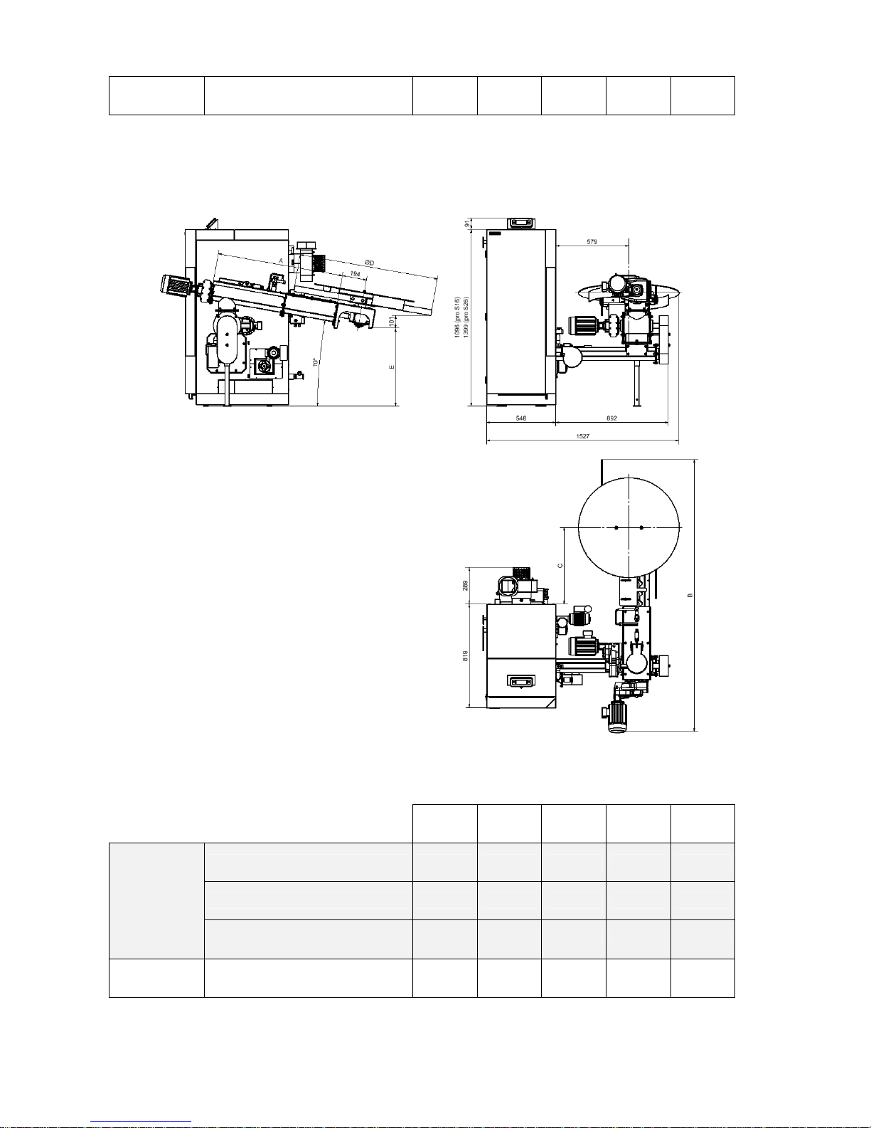
Fig. no. 5 Basic BENEKOV S16 and S26 boiler dimensions with lateral arrangement of feeding from
the bunker
Tab. no. 5 Parametric BENEKOV S16 and S26 boiler dimensions with lateral arrangement of feeding
from the bunker
A*
[mm]
B
[mm]
C
[mm]
D
[mm]
E
[mm]
Basic feeder arrangement
1000 2816 1732 1105 616
Feeder with extension of 1 m
2000 3801 2717 1105 442
Feeder
for container
φ 1200 mm
(740 dm3)
Feeder with extension of 2 m
3000 4786 3702 1105 268
Basic feeder arrangement
1400 3587 2126 1874 547
Feeder with extension of 1 m
2400 4572 3111 1874 373
Feeder
for container
φ 2000 mm
(2700 dm3)
Feeder with extension of 2 m
3400 5557 4096 1874 199

13
* Dimension "A" is specified by the client when ordering, based on the specific boiler room design.
Fig. no. 6 Basic BENEKOV S16 and S26 boiler dimensions with front arrangement of feeding from the
bunker
Tab. no. 6 Parametric BENEKOV S16 and S26 boiler dimensions with front arrangement of feeding
from the bunker
A*
[mm]
B
[mm]
C
[mm]
D
[mm]
E
[mm]
Basic feeder arrangement
1000 2400 757 1105 616
Feeder with extension of 1 m
2000 3385 1742 1105 442
Feeder
for container
φ 1200 mm
(740 dm3)
Feeder with extension of 2 m
3000 4370 2727 1105 268
Basic feeder arrangement
1400 3171 1151 1874 547
Feeder
for container
φ 2000 mm
(2700 dm3)
Feeder with extension of 1 m
2400 4156 2136 1874 373
14
Feeder with extension of 2 m
3400 5141 3121 1874 199
* Dimension "A" is specified by the client when ordering, based on the specific boiler room design.
Fig. no. 7 Basic BENEKOV S16 and S26 boiler dimensions with rear arrangement of feeding from the
bunker
Fig. no. 7 Parametric BENEKOV S16 and S26 boiler dimensions with rear arrangement of feeding
from the bunker
A*
[mm]
B
[mm]
C
[mm]
D
[mm]
E
[mm]
Basic feeder arrangement
1000 2144 603 1105 616
Feeder with extension of 1 m
2000 3129 1588 1105 442
Feeder
for container
φ 1200 mm
(740 dm3)
Feeder with extension of 2 m
3000 4114 2573 1105 268
Feeder
for container
Basic feeder arrangement
1400 2915 997 1874 547

15
Feeder with extension of 1 m
2400 3900 1982 1874 373
φ 2000 mm
(2700 dm3)
Feeder with extension of 2 m
3400 4885 2967 1874 199
* Dimension "A" is specified by the client when ordering, based on the specific boiler room design.
Fig. no. 8 Basic BENEKOV S51 boiler dimensions with lateral arrangement of feeding from the
bunker
Tab. no. 8 Parametric BENEKOV S51 boiler dimensions with lateral arrangement of feeding from the
bunker
A*
[mm]
B
[mm]
C
[mm]
D
[mm]
E
[mm]
Arrangement with 2 m feeder
2000 4770 2812 2374 400
Arrangement with 3 m feeder
3000 5755 3797 2374 226
Arrangement with 4 m feeder
4000 6740 4782 2374 52
Feeder
for container
φ 2500 mm
(4000 dm3)
Arrangement with 5 m feeder
5000 7725 5767 2374 -122

16
* Dimension "A" is specified by the client when ordering, based on the specific boiler room design
Fig. no. 9 Basic BENEKOV S51 boiler dimensions with front arrangement of feeding from the bunker
Tab. no. 9 Parametric BENEKOV S51 boiler dimensions with front arrangement of feeding from the
bunker
A*
[mm]
B
[mm]
C
[mm]
D
[mm]
E
[mm]
Feeder
for container
Arrangement with 2 m feeder
2000 4294 1643 2374 400

17
Arrangement with 3 m feeder
3000 5279 2628 2374 226
Arrangement with 4 m feeder
4000 6264 3613 2374 52
φ 2500 mm
(4000 dm3)
Arrangement with 5 m feeder
5000 7249 4598 2374 -122
* Dimension "A" is specified by the client when ordering, based on the specific boiler room design.
Fig. no. 10 Basic BENEKOV S51 boiler dimensions with rear arrangement of feeding from the bunker
Tab. no. 10 Parametric BENEKOV S51 boiler dimensions with rear arrangement of feeding from the
bunker
A*
[mm]
B
[mm]
C
[mm]
D
[mm]
E
[mm]
Feeder
for container
Arrangement with 2 m feeder
2000 3851 1471 2374 400

18
Arrangement with 3 m feeder
3000 4836 2456 2374 226
Arrangement with 4 m feeder
4000 5821 3441 2374 52
φ 2500 mm
(4000 dm3)
Arrangement with 5 m feeder
5000 6806 4426 2374 -122
* Dimension "A" is specified by the client when ordering, based on the specific boiler room design.
4.2. Control and safety elements of the boiler
The control and regulation of the boiler is governed by a control unit - see separate instruction manual.
Safety components that monitor the safe operation of the boiler:
• The emergency thermostat is used to prevent the system from overheating. The manufacturer sets
the thermostat at 95°C, i.e. at a higher temperature than can be set on the boiler. The emergency
thermostat is positioned on the rear wall of the boiler in the CLIMATIX control unit cabinet.
• Thermal protection of the motor (thermal contact) is part of both fuel feeder motors and is used to
protect them from overheating in the case of fuel feeder blockage. It also retroactively stops the fan so
as to avoid burning of fuel in the container in the event of a fault. During normal operation, the motor
working temperature is up to 85 °C - such warming does not mean a failure.
• The turnstile is a device that mechanically separates the fuel between the screw conveyors (feeding
from the bunker + feeding into the boiler). In the event of re-ignition of fuel in the boiler feeding (e.g.
during long term power outage) the fuel in the tank does not ignite. Furthermore, the turnstile serves as
a partial fuel crusher. In the event of a longer piece reaching the turnstile, the turnstile crushes it into
smaller pieces.
• The cover limit switch of the bunker feeder shuts down the screw feeder and fan when the cover is
open. After proper closure both will return to normal operation.
• The emergency fire extinguishing system is another security feature preventing burning of fuel
through to the container. A temperature increase above 95 °C at the feeding out of the bunker results in
a thermostatic valve opening and the space being cooled with cooling water from the water main.
• The firing flap is located between the second and the third draft in the top part of the finned heat
exchanger and serves to regulate the flue gas temperature at the boiler outlet.
When operating the boiler when the flue gas temperature is higher than 100 °C the firing valve must be
closed, i.e. the firing flap lever on the side of the boiler must be rotated as much as possible upwards
(forwards) and secured with a locking screw. When firing (with cold chimney) or during long term
operation of the boiler at lower output it is recommended to operate the boiler with the firing valve
slightly open so that the flue gas temperature does not drop below 80 °C. In this case, the firing flap
lever must be rotated downward (backwards) and secured by a locking screw.
4.3. Boiler accessories
Standard accessories:
• Operating instructions and installation manual which includes a warranty card
• Operating instructions of the boiler control unit
• List of contracted service organizations

19
• Ash drawer
• Cleaning rake
• Automatic cleaning of heat transfer surfaces of the heat exchanger
• Flue gas exhaust - see fig. no. 15 and 16
Optional accessories:
• Automatic ignition - see fig. no. 11 and 12
• Ash remover - see fig. no. 13 and 14
• Rotary grate for combustion of less valuable fuels
• Basic container module with a diameter of 1200 mm (valid for BENEKOV S16 and S26)
• Basic container module with a diameter of 2 000 mm (valid for BENEKOV S16 and S26)
• Basic container module with a diameter of 2 500 mm (valid for BENEKOV S51)
• Additional fuel container module with a diameter of 1200 mm (valid for BENEKOV S16 and S26)
• Additional fuel container module with a diameter of 2 000 mm (valid for BENEKOV S16 and S26)
• Additional fuel container module with a diameter of 2 500 mm (valid for BENEKOV S51)
• 1 m extension of feeding from the bunker S26 (valid for BENEKOV S16 and S26) - see fig. no. 19
• 2 pieces of ceramic half-ring (valid for BENEKOV S51)
Optional accessories are not included in the basic price of the boiler.
Fig. no. 11 Automatic boiler ignition for S16 and S26
Fig. no. 12 Automatic boiler ignition for S51
Fig. no. 13 Boiler ash remover for S16 and S26

20
Fig. no. 14 Boiler ash remover for S51
Fig. no. 15 Boiler flue gas exhaust for S16 and S26

21
Fig. no. 16 Boiler flue gas exhaust for S51
Fig. no. 17 Basic fuel container module
Fig. no. 18 Additional fuel container module
Fig. no. 19 1 meter extension of feeding from the bunker S16 and S26

22
5. Boiler placement and installation
5.1. Regulations and directives
A boiler for solid fuels can be installed by an organization authorized to install these devices.
The installation must be made in accordance with the project subject to applicable regulations.
The heating system must be filled with water that meets the requirements of CSN 07 7401: 1992 and
importantly its hardness must not exceed the required parameters.
Tab. no. 12 Heating water parameters
Parameter Unit Value
Hardness mmol/l 1
Ca2+ mmol/l 0,3
Concentration of total Fe + Mn mg/l 0.3 (recommended value)
A) Regarding the heating system
ČSN EN 303-5:2013 Heating boilers - Part 5: Heating boilers for solid fuels, hand and
automatically stocked, nominal heat output of up to 500 kW - Terminology,
requirements, testing and marking.
ČSN 06 0310 2014 Heating systems in buildings - Design and installation
ČSN 06 0830:2014 Heating systems in buildings - Safety devices
ČSN 07 7401:1992 Water and steam for thermal energy equipment with working pressure up to
8 MPa
B) Regarding chimney
ČSN 73 4201:2010 Chimneys and flues - Design, implementation and connection of fuel
consumers
C) Regarding fire regulations
ČSN 06 1008:1997 Fire safety of heat installations
ČSN EN 13 501-1+A1:2010 Fire classification of construction products and building structures - Part 1:
Classification according to the results of response to fire tests
D) Regarding the electric network
ČSN 33 0165:1992 Regulations for electrical engineering. Marking of wires with colours or
numbers Executive provisions
ČSN 33 1500:1990 Regulations for electrical engineering. Revisions of electrical equipment
ČSN 33 2000-1 ed.2:2009 Low-voltage electrical installations - Part 1: Basic terms, determination of
basic characteristics, definitions

23
ČSN 33 2000-4-41 ed.2:2007 Low-voltage electric installations - Part 4-41: Protective measures to ensure
safety - Protection against electric shock
ČSN 33 2000-5-51 ed.3:2010 Electrical installations of buildings - Part 5-51: Selection and assembly of
electrical equipment - General requirements
ČSN 33 2000-7-701 ed.2:2007 Low-voltage electric installations - Part 7-701: Single-purpose equipment
and in special premises - Premises with tub or shower
ČSN 33 2030:2014 Electrostatics - Guidelines for the elimination of hazards due to static
electricity
ČSN 33 2130 ed.2:2009 Low-voltage electrical installations - Internal electrical wiring
ČSN 33 2180:1979 Regulations for electrical engineering ČSN. Connection of electrical devices
and appliances
ČSN 33 2350:1982 Regulations for electrical engineering. Regulations for electrical equipment in
difficult climatic conditions
ČSN 34 0350 ed.2:2009 Safety requirements for flexible cords and cord lines
ČSN EN 55 014-1 ed.3:2007 Electromagnetic compatibility - Requirements for household appliances,
electric tools and similar apparatus - Part 1: Emissions
ČSN EN 55 014-2:1998 Electromagnetic compatibility - Requirements for household appliances,
electric tools and similar apparatus - Part 2: Immunity - Product family
standard
ČSN EN 60079-14 ed.3:2009 Explosive atmospheres – Part 14: Design, selection and erection of electrical
installations
ČSN EN 60335-1 ed.2:2003 Electric appliances for household and similar purposes - Safety - Part 1:
General requirements
ČSN EN 60335-2-102:2007 Electric appliances for household and similar purposes - Safety - 2-102:
Particular requirements for appliances burning gas, oil and solid fuel
containing electrical connections
ČSN EN 60445 ed.4:2011 Basic and safety principles for man-machine interface, marking and
identification - Marking of conductors with colours or letters and numbers
ČSN EN 61000-3-2 ed.3:2006 Electromagnetic compatibility (EMC) - Part 3-2: Limits - Limits for harmonic
current emissions (equipment with input phase current <= 16 A)
ČSN EN 61000-3-3 ed.2:2009 Electromagnetic compatibility (EMC) - Part 3-3: Limits - Limitation of voltage
fluctuations and flicker in low-voltage supply systems for equipment with
rated current <=16, not subject to conditional connection
E) Regarding noise
ČSN EN ISO 3746:2011 Acoustics - Determination of sound power levels and sound energy levels of
the sources of noise using sound pressure - Survey method with measuring
lateral surface over a reflecting plane
ČSN EN ISO 11202:2010 Acoustics - Noise emitted by machinery and equipment - Determination of
emission sound pressure levels at a work station and at other specified
locations using approximate environmental corrections
F) Regarding machine equipment
ČSN EN 614-1+A1:2009 Safety of machinery - Ergonomic design principles - Part 1: Terminology and
general principles
ČSN EN 953+A1:2009 Safety of machinery - Guards - General requirements for the design and
construction of fixed and movable guards
ČSN EN 1037+A1:2008 Safety of machinery - Prevention of unexpected start up
ČSN EN ISO 12100:2011 Safety of machinery – Basic concepts, general principles for design.
ČSN EN ISO 13857:2008 Safety of machinery - Safety distances to prevent danger zones being
reached by the upper and lower limbs
5.2. Boiler placement options
Boiler placement with regard to the electric network:

24
• The boiler must be positioned so that a plug socket (400V / 50Hz) is always accessible.
• The boiler is connected to the mains with a fixed and flexible power supply cord with standardized plug.
• Protection against electric shock must be made in accordance with valid ČSN EN standard (see chap.
5.1.)
Boiler placement with regard to fire regulations:
1. Positioning on a floor made of incombustible material
• Place the boiler on an incombustible thermally insulating pad exceeding the boiler floor plan on all
sides by 20 mm.
• If the boiler is located in the basement, it is advisable to place it on a substructure at least 50 mm
high. The boiler must stand horizontally so any unevenness of the substructure must be eliminated
by screwing or unscrewing the foot of the fuel container beneath the fuel screw feeder.
2. Safe distance from flammable materials
• The minimum allowable distance of the outer contours of the boiler and flue gas ducting from
flammable materials (see detailed specifications in ČSN EN 13 501-1+A1:2010) during installation
and operation of the boiler must be at least 400 mm.
Boiler positioning with regard to the necessary handling space:
• Basic environment AA5 / AB5 according to ČSN 33 2000-1 ed.2:2009
• The handling space left in front of the boiler must be at least 1000 mm
• Minimum distance between the rear part of the boiler and the wall must be 500 mm
• The gap on the side of the fuel container must be at least 500 mm
• The gap on the side of the boiler body must be at least 500 mm for the possibility to clean the convective
area of the heat exchanger and connection of the ash remover
• The gap above the fuel container must be at least 1000 mm (for BENEKOV S16 and S26 boilers) and
1400 mm (for BENEKOV S51 boiler) to allow full opening of the fuel tank cover.
Fig. No. 20 Placement of the boiler in the boiler room
Boiler positioning with regard to the chimney:

25
• The BENEKOV S16 and S26 boiler is connected to the chimney using a metal pipe with a diameter of
145 or 150 mm.
• The BENEKOV S51 boiler is connected to the chimney using a metal pipe with a diameter of 200 mm.
Fuel placement:
• Pellets are recommended to be stored in their original packaging from the manufacturer (PET bags or
"big bags") in a dry place.
• Do not store fuel behind the boiler or store it next to the boiler within a distance shorter than 400 mm.
• The manufacturer recommends keeping the min. distance between the boiler and fuel at 1000 mm or to
store the fuel in a different room away from the boiler.
The room where the boiler is installed must be provided with permanent intake and outlet of air for
combustion and ventilation. Air consumption of:
- BENEKOV S16 at nominal output is about 45 m3 . h-1
- BENEKOV S26 at nominal output is about 75 m3 . h-1
- BENEKOV S51 at nominal output is about 150 m3 . h-1
According to regulations, an authorized person must perform the connection of the heating system pipeline
or heater heating element pipeline.
NOTE: When connecting the boiler to the heating system the lowest point as close to the
boiler as possible must be equipped with a drain tap.
6. Commissioning of the boiler - instructions for contracted service
organizations
Commissioning can only be performed by a contracted service organization authorized to conduct
this activity.
6.1. Electric connection using via connectors
In the course of putting the boiler into operation there is no need to tamper with any electrical connection of
the boiler’s control unit. Wiring of electrical components of the boiler and peripheral devices (e.g. ash
remover, automatic ignition, etc.) is via the connectors, which allows for quick and easy disconnection from
(or connection to) the boiler control unit.
Depending on the variant and equipment the boiler may be fitted with connectors marked with the following
symbols:
- Fuel feed drive connector
- Fan connector
- Automatic ignition connector
- Ash remover connector

26
- Flue gas exhaust connector
- Circulation pump connector
- Room thermostat connector, respectively the equitherm control
- Spontaneous combustion sensor connector
- Lambda probe connector
- Limit switch connector
Spare connector plugs (e.g. for connecting a room thermostat, circulation pump, etc.) are placed in a
package in the ash tray drawer during transport from the factory. Prior to putting the boiler in operation it is
necessary to fit all these loose connector plugs to the boiler, even if they are not used.
When connecting the connectors you must avoid any confusion. Please connect the connector plugs and
sockets with the identical symbols.
Before connecting the room thermostat, respectively equitherm control, it is necessary to remove bridging
from the plug of the relevant connector. The room thermostat connector, respectively equitherm control can
only be connected to a thermostat with free potentialless contact (eg. SIEMENS REV, HONEYWELL CM…).
No external voltage can be connected to any of these terminals.
Fig. no. 21 Connection dimensions of BENEKOV S16 boiler

27
Fig. no. 22 Connection dimensions of BENEKOV S26 boiler

28
Fig. no. 23 Connection dimensions of BENEKOV S51 boiler

29
6.2. Verification activities before start-up
The following checks must be performed before start-up:
a) Filling the heating system with water
The water used for filling boiler and heating systems must be clear and colourless, without suspended
solids, oil and aggressive chemicals. Its hardness must comply with ČSN 07 7401: 1992 and it is
essential that in case the water hardness does not comply, it must be treated. Even multiple heating of
water with a higher hardness does not stop salt build-up on the walls of the exchanger. 1 mm of calcite
reduces the heat transfer from metal to water at the given point by approximately 10%.
Heating systems with an open expansion tank allow direct contact between the heating water and the
atmosphere. During the heating season the water expanding in the tank absorbs oxygen which increases
corrosion and at the same results in significant water evaporation. Refilling can only be performed with
water treated according to ČSN 07 7401:1992. The heating system must be thoroughly flushed in order to
wash out all impurities.
During the heating season it is necessary to maintain a constant volume of water in the heating system.
When refilling the heating system with water no air must be sucked into the system. The boiler and
heating system water must never be discharged or taken for use except in emergencies like repairs etc.
Water discharge and filling with new water increases the danger of corrosion and scaling.
If it is necessary to refill the heating system with water only do this when the boiler is cold to
prevent damage to the steel heat exchanger.
b) Heating system tightness
c) Connection of emergency fire-fighting equipment to the water distribution system
d) Connection to the chimney - must be approved by a chimney sweeping company
e) Ceramic reflector of BENEKOV S16 and S26 boilers (fig. no. 24, pos. 7) fitted into the combustion
chamber of the burner, i.e. laid on the obliquely welded beams (8) in the boiler body and attached to the
back wall of the combustion chamber.
Ceramic reflector of BENEKOV S51 boiler (fig. no. 25, pos. 7) fitted into the combustion chamber of the
burner, i.e. laid on the horizontally welded beams (8) in the boiler body and attached to the back wall of
the combustion chamber.
f) Electric connection
The assembly completion and heating test must be recorded in the "Guarantee certificate".
6.3. Putting into operation
1. Fire the boiler.
2. Bring the boiler to operating temperature. The recommended operating temperature of the output
heating water is 65 to 80 °C.
3. Check the boiler tightness again.
4. Carry out the heating test according to relevant standards (see the Guarantee certificate)
5. Acquaint the user with the boiler operation - see chapter 7.
6. Make a record in the Guarantee certificate.

30
Fig. no. 24 Section of the combustion chamber of the BENEKOV S16 and S26 boiler
Fig. no. 25 Section through the combustion chamber of the BENEKOV S51 boiler
1. Feeding to the boiler
2. Screw shaft
3. Grate
4. Secondary air tube
5. Ceramic reflector (1 pc)
6. Ceramic reflector beam
1. Feeding to the boiler
2. Screw shaft
3. Grate
4. Ceramic half-ring (2 pcs)
5. Distribution of secondary air
6. Ceramic reflector (2 pc)
7. Ceramic reflector beam
1
2
3
4
5
6

31
8.
7. Boiler operation by user
7.1. Making fire in the boiler
1. Check the water volume in the heating system.
2. Check whether the stop valves between the boiler and the heating system are open.
3. Check the circulation pump functionality.
4. Clean the burner and ash tray drawer.
5. Fill the container with prescribed fuel - see Chap. 3. If the container is equipped with a lid, close the
container after refilling in order to avoid potential false air intake into the burner through the screw
feeding device.
6. Connect the boiler to the mains (400V/50Hz) via power cord with plug.
7. Put the control unit into operation (see separate control unit instruction manual).
8. If the boiler is equipped with automatic ignition (optional), leave the boiler without intervention. The
control unit evaluates the status of the boiler and makes fire (see separate control unit instruction
manual). During the boiler firing and operation the door must be permanently closed.
9. If the boiler is not equipped with automatic ignition, it is necessary to make fire manually (see
separate control unit instruction manual). Using the control unit manual mode deliver the fuel into the
combustion chamber of the boiler. Leave the screw feeding device switched on until the fuel appears in
the burner (2 cm below the edge of the grate). Subsequently switch the screw off, place fire setting
material on the fuel (eg. paper, dry wood chips, PEPO, solid alcohol or other material intended for this
purpose), ignite it and let it flame up (approx 1-2 minutes). Then add a small amount of prescribed fuel
with a shovel to the fire setting material and switch on the fan. In the event that the fire is extinguished,
repeat the manual firing procedure. Close the door and let the fire flame up well (about 3-5 minutes).
1
2
3
4
5
6
7

32
7.2. Boiler operation
After fuel flame-up the boiler switches (see separate control unit instruction manual) to automatic operation,
which includes the fan, as well as cycling of the fuel screw feeder. The control unit display visualizes the
basic data regarding the boiler operation.
The boiler operation is automatic until the desired water temperature is reached. As soon as the required
water temperature is reached, the boiler automatically switches to the "attenuation" mode where it remains
until the temperature drops below the medium heating setpoint.
During a power outage (400 V, 50 Hz) the boiler control unit remembers its status and restores to this when
the power returns.
If the heating water temperature exceeds 95 °C, the emergency thermostat will respond to shut down the
boiler irrespective of the control unit. When you turn off the emergency thermostat the control unit indicates
overheating.
The emergency thermostat can be switched on only when the temperature falls below the set value by about
20 °C. This is done by unscrewing the black cap on the emergency thermostat and pushing the colour
button. The black cap must subsequently be restored to its place.
To prevent unwanted switching of the safety thermostat due to the thermal inertia of the boiler, it is
recommended to operate the boiler at outlet heating water temperatures up to 80 °C.
In case of repeated switching off of the boiler by the emergency thermostat, the boiler must be shut down
and the user must determine the cause of the repeated overheating.
7.3. Boiler shutdown
Before the boiler is shut down, it is necessary to use manual control to push the hot fuel from the feed area
of the boiler and burner into the ash tray drawer. This is not necessary for short repairs when an operator is
present.
IMPORTANT ADVICE:
• This appliance is not intended for use by persons (including children) whose physical, sensory
or mental disability or lack of experience and knowledge prevents them from using the
appliance safely.
• It is unacceptable to leave children unattended near the boiler when it is in operation.
• If there is a danger of combustible vapours or gases building-up in the boiler room or there is
work involving a temporary fire or danger of explosion (gluing of floorings, painting with
combustible paints, etc.) taking place in the boiler room, the boiler must be shut down before
beginning any work.
• When transporting fuel into the combustion chamber before firing, it is necessary to check the
amount of fuel in the burner visually, not by inserting hands into the burner. There is a risk of
injury from the rotating screw shaft.
• It is forbidden to fire the boiler using flammable liquids.
• Observation of the flame during boiler operation is possible by opening the door. If it is
necessary to open the door during boiler operation (e.g. for removal of ash from the ash tray
drawer), it should be noted there is an increased danger of sparks and smoke development in
the boiler room. If this happens the door must be closed immediately. The door must only be
opened with caution during boiler operation, i.e. slightly ajar at first then wait until the exhaust
gases from the combustion chamber are extracted and only then open it completely.
• During operation it is forbidden to overheat the boiler in any manner.
• It is not allowed to place any articles made of flammable materials on the boiler or within a
distance smaller than the safe distance from it (see chap. 5.2.).

33
• All flammable substances must be at a minimum distance of 1500 mm from the boiler when
removing ash from the boiler. The ashes must be put into incombustible containers with lids.
• When operating the boiler at a temperature below 60 °C, the steel boiler body is covered with
dew and so-called low-temperature corrosion occurs, which reduces its service life. Therefore,
the boiler must be operated at a temperature of 60 °C and higher.
• After the heating season, it is necessary to thoroughly clean the boiler including the flue gas
duct. The boiler room must be kept clean and dry.
• It is forbidden to interfere with the boiler structure and wiring.
• The boiler is operated with a fan.
• The boiler is operated at an overpressure at the flue gas outlet.
• The boiler operates in conditions without condensation.
7.4. Residual risks and their prevention
Risks arising during operation of the boiler under the conditions of expected use and logically foreseeable
misuse have been minimized using currently available technology.
Despite its design, structure and technical features, during the operating life of a boiler certain residual risks
remain.
These risks in particular result from inattention by the boiler operator and failure to observe safety
rules during operation.
To further reduce these risks and ensure your safety we bring to your attention certain residual risks that
cannot be removed by any technical design.
a) Electrical risks
Mounting, maintenance and repairs of electrical parts of the boiler must be carried out only by
professionally qualified personnel in accordance with applicable technical regulations and standards;
Supply wiring must comply with applicable regulations;
Power supply cable and wiring of the boiler must be regularly checked and maintained in the
prescribed condition;
In the event of any damage to electrical equipment, the boiler must be shut down, unplugged from
the mains and a qualified repair must be undertaken;
It is forbidden to interfere with the wiring of safety circuits, or perform any unauthorized interventions,
which are related to the equipment’s safety and reliability.
b) Thermal risks
The boiler must not be exposed to higher working pressures than prescribed;
It is forbidden to overheat the boiler;
The boiler must be protected against low-temperature corrosion by a suitable connection with an
automatic return temperature protection;
The boiler can burn only specified fuel;
It is prohibited to store flammable liquids near the boiler;
Minimize the risk of ignition by setting suitable attenuation parameters;
During boiler operation pay maximum attention to the risk of burns from sources of heat.
c) Risks posed by fuel handling
Handling fuel results in emission of solid particles. Therefore, the operator should wear appropriate
protective equipment according to the degree of dust generation;
Because it is a fuel, it is necessary to observe appropriate fire regulations and keep a suitable
portable fire extinguisher accessible.
d) Ergonomic risks
The boiler must stand horizontally in the boiler room;
It is forbidden to put hands into the screw feeder;
All doors, lids and covers must be completely closed during boiler operation.

34
8. Boiler maintenance
NOTE: Before performing maintenance and cleaning the boiler and/or feeder mechanism, it is
necessary to make sure the boiler is disconnected from the power supply (plug pulled out of the
socket). Risk of injury!
1.) It is necessary to ensure timely refuelling. If a small amount of fuel remains in the container, it must be
refilled immediately to prevent extraction of "false air" and a smoked container.
2.) If the boiler is correctly adjusted, the ash has the form of a fine grey powder, which accumulates in the
ash tray drawer. The combustion compartment has self-cleaning design and in the course of normal
operation the boiler’s ash tray drawer has to be emptied once or twice a week. It is necessary to use
protective gloves for this activity.
3.) In continuous operation of the boiler it is recommended to clean the heat transfer area of the combustion
chamber or the exchanger fins once a week. The heat transfer surfaces can be subject to clogging,
which can greatly affect the heat transfer and thus the efficiency of the boiler. Occasional cleaning of the
inside of the grate (on a monthly basis) should not be forgotten. Its clogging impairs the flow of
combustion air to the burner nozzles. The boiler must be shut-off by the main switch at least 1 hour
before cleaning the grate. After the heating season the entire boiler must be carefully and completely
cleaned.
4.) The minerals contained in the fuel can form hard deposits during operation in the area of the burner. This
can subsequently cause a complete blockage of the screw shaft of the feeding mechanism. To avoid the
risk of this phenomenon, it is recommended to check the burner zone at least monthly and in the event
of hard deposits, mechanically remove any stuck material.
5.) It is further recommended to perform occasional external cleaning of drives and fans. Cleaning must be
done using a dry brush. The boiler must be disconnected from the power supply during this time.
6.) A refractory ceramic reflector is located above the boiler burner. It does not require any special attention.
Any fly ash deposited on the surface of the reflector can be regularly removed, but it does not affect its
function.
7.) For a reliable operation of the turnstile during fuel feeding into the screw feeder, it is necessary to
maintain proper tension of the chain, i.e. the deflection in the middle between the sprockets must be in
the range of 6 to 10 mm. If the deflection is bigger, the chain must be replaced. When checking the
tension and handling of the chain the boiler must be shut down. Risk of hand injury!
8.) In case of a screw fuel feeder blockage the two motors are protected against damage by the thermal
contact (working temperature of the fuel feeder motor is up to 85 °C), which after exceeding the
critical temperature shuts down both feeder motors and the fan(s). If this happens, the boiler must be
shut down and repaired.
9.) Since pressurising occurs in the burner area during fan operation, it is necessary to ensure perfect
tightness of the boiler (boiler door, the top cover of the boiler body, etc.).
10.) Occasionally perform a visual check of the emergency fire-fighting equipment.
11.) In the event of an emergency (electricity outage for long periods, etc.) or if fuel burns through the
increase in temperature opens the thermostatic valve and any fuel is extinguished with water from the
water main. Before restarting the boiler it is necessary to remove wet fuel, and fire the boiler in a
standard manner (see chap. 7.1.).
12.) The gearboxes are filled with synthetic oil in compliance with factory standards therefore no further
maintenance is required.

35
9. Troubleshooting
If you have problems with the operation of the boiler, try some of the following solutions:
SYMPTOM CAUSE SOLUTION
The boiler is not
connected to the mains.
Connect the boiler to the mains (400V/50Hz) via
power cord with plug.
The display does not
show any data.
Boiler controller failure. Replace the boiler controller.*
Boiler drive cable Is
disconnected (or
damaged).
Connect (or replace) the boiler drive cable.*
Boiler drive is damaged. Replace the boiler drive.*
Screw feeding device
does not work.
There was a motor
overheating and thus the
motor thermal protection
was activated.
Let the motor cool, after cooling the motor will
restart automatically.
The fuel feeder contains
an obstacle (stone, etc.).
Demount the fuel feed screw and remove the
obstruction. Reassemble the feeder.*
The fuel contains a
substantial quantity of
dust.
Remove unsuitable fuel from the boiler, refill the
container with prescribed fuel.
Repeated activation of the
motor thermal protection.
The alignment of the
drive, screw shaft and
burner is not correct.
Disassemble the fuel screw feeder, clean and
reassemble it with emphasis on ensuring the
alignment of the individual components.*
The container does not
contain fuel.
Refill the container with prescribed fuel.
Overall wear of the screw
shaft.
Replace the screw shaft.*
The screw shaft rotates,
though the fuel is not
transported into the
combustion chamber.
The turnstile chain was
damaged.
Replace the turnstile chain.*
Boiler fan cable is
disconnected (or
damaged).
Connect (or replace) the boiler fan cable.* Boiler fan does not work.
The fan is damaged. Replace the boiler fan.*
The fan was clogged by
dust.
Clean the boiler fan.* The fan is noisy in
operation.
The fan bearings are
worn.
Replace the entire boiler fan.*
The fan does not rotate
during boiler modulation
at the lowest output
values.
The set values of the fan
speed are too low.
Increase the fan speed on the boiler controller
so as to guarantee its smooth operation.
Water from the
emergency fire-fighting
equipment leaked into the
fuel feeder.
The fuel burnt through to
the fuel feeder, which
activated the thermostatic
valve.
Remove wet fuel from the feeder, fill the
container with new dry fuel and start-up the
boiler.
Water from the
emergency fire-fighting
equipment leaks into the
fuel feeder.
The thermostatic valve on
the feeder leaks.
Replace the thermostatic valve.
The boiler is filled with wet
fuel.
Refill the container with dry fuel. The walls of the fuel tank
are covered with droplets
of water.
The temperature in the
boiler room is low (about
12 °C or less)
The boiler room requires a higher air
temperature (boiler room wall insulation,
installation of heating radiator to the boiler room,
etc.).
A short time passed after
firing in the boiler.
Let the boiler thoroughly flame up. The boiler cannot reach
the rated output during
operation.
Fuel dosing is set to a
lower output.
Adjust the fuel dosing according to the control
unit instruction manual.

36
The boiler uses nonprescribed fuel (high
humidity, lower calorific
capacity, etc.)
Refill the container with prescribed fuel.
The boiler is clogged with
soot.
Clean the heat transfer surfaces of the boiler
body.
The boiler is overheating. Reduce fuel dosage.
High chimney draft. Install a chimney flue draw limiter (this activity
must be performed by a specialized company).
Ceramic reflector is not
installed in the boiler
body.
Install a ceramic reflector according to the
instruction manual.
The flue gas temperature
is higher than specified in
the instructions.
The firing flap in the boiler
body is open.
Close the firing flap using the cleaner lever and
firing flap and secure it with a locking screw with
a plastic head.
Low chimney draft. Have a chimneysweeper check the value of the
chimney draft. If the measured value is less than
the value required (see instructions), it is
necessary to make adjustments to the chimney.
The boiler door and / or
the top cover of the boiler
body and / or the fuel tank
cover is not closed
properly.
Close the boiler door and / or the top cover of
the boiler body and / or the fuel tank cover
properly.
The sealing cord of the
boiler door and / or the
top cover of the boiler
body are worn
(damaged).
Replace the worn (damaged) sealing cords.*
Smoke appears in the
boiler room or fuel
container.
The fuel container is
empty.
Refill the container with prescribed fuel.
Low volume of
combustion air.
Increase the boiler fan output (see the control
unit instruction manual).
The boiler is overheating. Set the boiler output to nominal value (see the
control unit instruction manual).
The fan is damaged. Replace the boiler fan.*
The boiler body gets
clogged with soot after a
short time.
The grate is clogged with
ash and dust.
Clean the grate.
Caking ash on the grate. Other than prescribed fuel
is used for combustion.
Fill the container with prescribed fuel (see chap.
3).
Fuel dosing is not set
correctly.
Reduce the dosage of fuel in the burner (see the
control unit instruction manual).
Moist fuel is used for
combustion.
Refill the container with prescribed (dry) fuel.
Emergence of a
significant part of
unburned fuel in the ash
tray drawer.
The output of the fan is
adjusted incorrectly and
the air flow blows fuel out
of the burner.
Reduce the boiler fan speed (see the control unit
instruction manual).
* - This activity can only be performed by a service organization trained and authorized by BENEKOVterm
s.r.o.
10. Guidelines for sustained compliance with the environmental
parameters of the product
Continuous environmentally friendly operation of the boiler requires full compliance with the provisions of this
manual, especially:

37
• Burn only fuel whose parameters are guaranteed by the manufacturer for fuel within the range specified
in table 4, chap. 3.
• Comply fully with the provisions of chap. 7 and 8.
11. Instructions for product disposal after the end of its service life
Since the product is made of common metal materials, it is recommended to dispose of the respective parts
as follows:
- boiler body, casing - via KOVOŠROT
- other metal parts - via KOVOŠROT
- SIBRAL insulation material - standard waste
- ORSIL T insulation material - standard waste
- TECHROCK insulation material - standard waste
12. Guarantee and liability for defects
The manufacturer provides a warranty for the boiler for a period of 24 months from the date of sale to
the end user, assuming that it will be used and operated in accordance with the conditions specified
in the instruction manual.
The user is obliged to entrust the boiler installation, commissioning and troubleshooting, going beyond chap.
7 and 8 only to a professional contractual service accredited by the boiler manufacturer BENEKOVterm
s.r.o., otherwise the guarantee is void.
A precondition for the warranty is the installation of the boiler in the heating system so that the
temperature of the water returning to the boiler is monitored AUTOMATICALLY at a minimum value
of 53 °C. This can be achieved through a variety of hydraulic circuits depending on the controller
used in the boiler. More information - see "Technical documentation for installation of automatic
boilers."
The solution should be proposed by a designer, based on knowledge of the complete heating
system.
If the boiler is operated in accordance with the instructions provided in the "Boiler operating and instruction
manual", it does not need any special service interventions.
The "Certificate of quality and completeness of BENEKOV boiler" serves as a "Guarantee Certificate" after
having been completed by contractual service organization.
The boiler must be subjected to regular maintenance - see chap. 8.
The manufacturer shall not be responsible for any loss of profits, goodwill or contracts, or any
incidental, special or consequential damages arising in connection with the use or inability to use
this product.
Each notice of defect must be made immediately after its detection, always in writing or by
telephone. In the event of a claim it is always necessary to provide the serial number of the boiler.
The manufacturer shall not admit a claim if the above instructions are not followed.
The guarantee does not apply to cases caused by improper operation of the device, failure to comply
with the technical conditions of operation, normal wear and tear, wilful damage and damage to the
equipment which arose due to unavoidable and natural disasters (fire, water, theft, violent damage,
etc.).
No warranty applies unless the seller duly completed the warranty certificate.

38
The manufacturer reserves the right to make changes to the product, such as innovations, that may
not be included in this manual.

39
BENEKOVterm s.r.o.
Masarykova 402
CZ - 793 12 Horní Benešov
Tel.: +420 554 748 008, Fax :+420 554 748 008
E-mail: info@benekov.com, www.benekov.com
Issue: 2016/06
 Loading...