

Page 1

TWIG PROTECTOR
Configuration Guide
Publication number: YZ3301-03
All rights reserved. © GeoSentric Oyj, 2009
1. Installing software and drivers
You can find latest Protector software
and necessary drivers in the support
pages in www.twigworld.com
instructed in the quick guide under
support section. Connect Protector to
your computer with Mini USB cable. The
operating system will notify you of
finding new device, and prompt for
installing necessary drivers. Select to
install drivers manually, and then
browse for drivers in your local folder
where you downloaded the drivers from
support web site.
Note that since Protector uses two ports,
the system will prompt for drivers twice.
When this happens, repeat the manual
installation of drivers. After the
installation is done, you may need to
restart and reconnect Protector before
changes take effect.
To install Protector Configuration
software, download the compressed
software file (configure.exe) from the
support pages and save it in your
as
computer. The configuration software
is ready to be used without separate
installation. Make sure the needed dllfiles are located in same directory as
the main program.
2. Opening connection
Once the software and drivers are
installed, you can establish a
connection between Protector and
your computer.
Note that Protector must be connected
to computer when using the
configuring program.
Connect Protector to your computer
with Mini USB cable attached to the
charging adapter ( AUG81) or
programming station ( AGP81).
Note that the TWIG Desktop charger
CTA81 is not supported for USB
connection.
Then open the configuration software
by double-clicking Configure.exe-file
on your computer.
Protector connects automatically to
the right COM port and connection is
indicated with “Connected to device”
text in the user interface left lower
corner.
The connection between Protector and
PC is established, and existing Protector
settings are displayed in configuration
settings fields.
3. Device information
The Info box displays details on your
Protector , including the Serial no, IMEI
(International Mobile Equipment Identity)
code as well as software version and
GSM module numbers.
You can open various settings from the
top tab row of Protector configure
software. Click the desired tab, and the
available settings will open in the
software main view.
Note that Protector settings are case
sensitive. If there are wrong characters,
or other invalid values set in the
configuration field, those are ignored
and default value is taken into use.
Settings are transferred to unit using the
Update device button.
Page 2
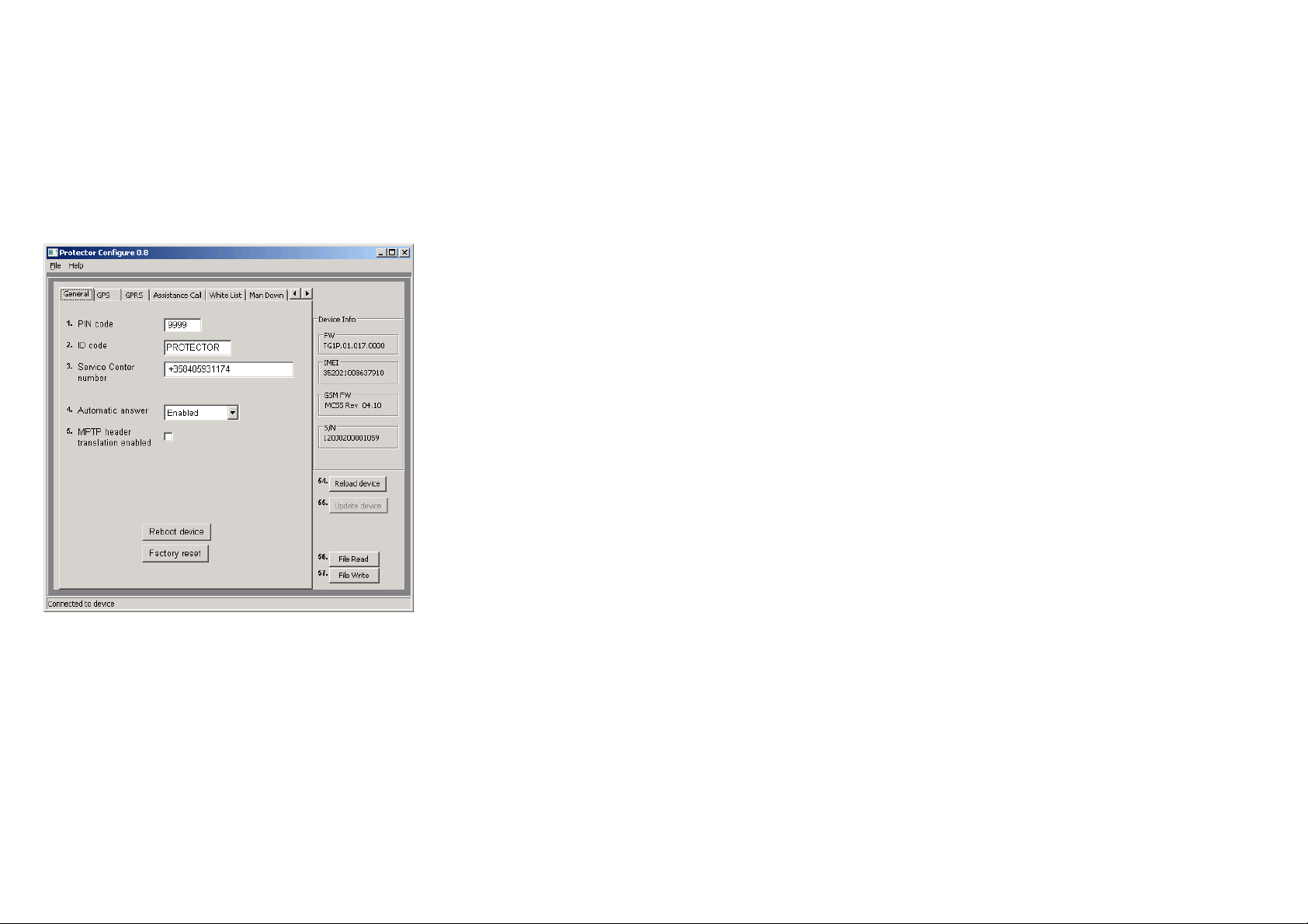
4. General configuration settings
Connect Protector to your. You can edit
and define several settings, including
security settings and available
connections, to be used with your
Protector.
Reboot device button will restart the unit
and reload automatically the new
settings if they are stored. Reboot is
needed after changing parameters.
Factory reset will clear all settings from
the unit.
Relaod device button will read all the
settings from the device since last save.
All current settings in the PC program
will be overwriten.
Update device will save the current
settings in the PC program to device.
If any setting is invalid, they will be
clared in device reboot.
File read will read configure_save.bin
file from the Configure.exe working
directory and show them on PC
program.
File write will write the current settings
in the PC program to
configure_save.bin in the working
directory.
Config 1: PIN Code
PIN code (4 digits) is used to unlock
Protector’s SIM card, unless you are
using a SIM card in which the PIN
code is disabled. Default value for PIN
code is 0000. Replace the value with
your own PIN code, or leave the field
blank if the PIN code has been
disabled. If the PIN code is defined
incorrectly, you won’t be able to turn
on your Protector. After three failed
attempts, the SIM card will be blocked.
If your SIM card gets blocked, you
need a PUK code (8 digits) to open it.
Remove the SIM card for Protector
and install it into a phone compatible
with your SIM card. When trying to
open the phone, it will prompt you for
the PUK code. After entering the PUK
code, key in a new PIN code. You can
then install the SIM card back to
Protector. If you fail to key in the correct
PUK code 10 times in a row, your SIM
card will be permanently blocked. If this
happens, contact your network operator
to get a new SIM card.
Config 2: ID
You can define identification for your
Protector. This code may contain both
numbers and letters, and it is case
sensitive. Default value for the ID code
is: Protector. Config 3: Security code
Security code is used when
configuration Protector and activating its
different features. The security code
consists of 4 digits. Default security
code is 0000.
Config 3: Service Center Number
Defines the number where generic
Mobile originated messages like low
battery or docking & undocking are
send. It also defines the number allowed
to make remote configuration via SMS.
Config 4. Automatic answer
Page 3
Allows restricting incoming calls as well
as allowing automatic answer for
incoming call. As default all incoming
calls are allowed and they ring.
Note if white list is in use handling
calls or calls and SMS’s it will
override this setting.
Config 5.Translate header
Translate header defines whether
special characters (? and !) in the
beginning of SMS based MPTP
messages are replaced by letters or not.
The replacement is necessary with
some mobile phone operator systems
(e.g. Russian and China). If Translate
header is set active the question mark
(?) in the beginning of MPTP requests is
replaced by the letter Q. The
exclamation mark (!) in the beginning of
MPTP updates and replies is replaced
by the letter E.
Unselecting restores the original settings
for MPTP messages. Question mark (?)
is used in the beginning of requests, and
exclamation mark (!) is used as the start
character for replies and updates.
Default value for Translate header is
inactive. Note that to use Protector with
TWIG Discovery Pro, or some other
back-end devices, you need to make
sure that Translate header is
configured correspondingly also in the
other device. If MPTP message start
character is configured differently in
the other device, sending and
receiving MPTP messages from
Protector is not possible.
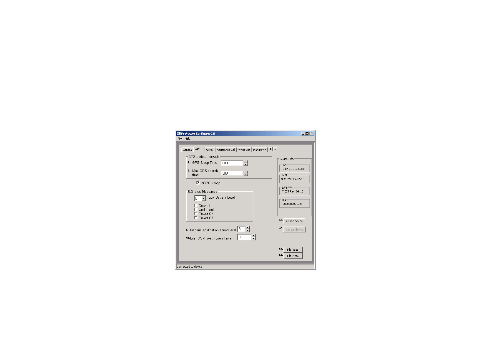
5. GPS & STATUS MESSAGING
SETTINGS
Config 6 GPS Sleep time
You can define how frequently GPS is
updating position while not controlled
by other processes like tracking. Time
interval can be set to: 1...65535 seconds
(18:12:25 hrs) Default value is 600 (ten
minutes).
Config 7: Max GPS search time
You can define for how long GPS is
trying to get a refreshed position after
receiving a position request. If the
refreshed position is not acquired within
that time, Protector sends position
update using the previously stored
position. Valid values for GPS search
time are between: 120... 600 (seconds).
Default value is 300 (five minutes).
AGPS usage will determine whether
AGPS service is used. ( future option)
Config 8: Status messages
You can define if the Protector is
sending a message to Service Center
number from various events.
Protector can alert you when its battery
level is declined under certain level. You
can define the alarm level at 25, 50, or
75 percentage of full battery charge. If
the value is set to 0, it means that the
alarm is deactivated. Default value for
the alarm is 0.
Page 4

Note, that battery levels can vary
substantially when using the device.
This may cause wrong or repeating Low
battery alarms.
Docked message is sent when Protector
is placed to charging station While
undocked message is sent when picking
up the device from charger station.
Power on message can be sent when
device is started and Power off when
user turns off the device or it turns itself
off due to low battery.
Config 9: Generic application sound
level.
Defines the volume level, that is used to
play warning, notification & incoming call
tones. Value can be set from 1..5, if 0 is
used, tones are not used at all. Default
value is 3.
Config 10: Lost GSM beep tone interval.
You can define the interval for BEEP
tone if the roaming GSM network has
been lost. You can set the interval
between 20…65534 seconds. If you set
0, the tone will never be played. Default
value for this setting is 0.
6. GPRS SETTINGS
Config 11 ID
User ID is a number used in identifying
your phone in server. Usually this is
the phone number that your Protector
device is using.
To use TWIG Web Finder service with
your Protector, make sure that
Protector is configured with the same
phone number as you have defined in
Web Finder.
Config 12: APN
The Access Point Name used for GPRS
communication.
Define the entire APN value in the field.
The values typically can be left empty of
replaced with “internet”. You can get the
correct APN from you GSM operator.
Config 13 port : GPRS port number
A port number is required for GPRS
communication. The value can be set
between 0...65535. As default, TWIG
Web Finder service port 8484 is used.
Note that it may be prevented to use
other than Default 8484.
Config 14 GPRS IP address
Key in the IP address that is used in
GPRS communication. As default, TWIG
Web Finder IP address 192.83.5.99 is
used. Note that it may be prevented to
use other than Default IP address.
Config 15 & 16: GPRS DNS 1-2
Some GPRS networks require that
primary domain name server (DNS1) is
specified. Define the DNS as an IP
address. Maximum length for DNS1
name is 16 characters. Default value for
Page 5

DNS1 is 127.0.0.1 and for DNS2
127.0.0.2.
Config 17: GPRS user name
If the GPRS network in use requires a
user name for GPRS log-in, define the
name here.
Config 18: GPRS password
If the GPRS network in use requires a
password for GPRS log-in, define the
word here.
Config 19: Service Number
Number to use for SMS telematics if
GPRS connection is not available and
mode is set to use SMS if GPRS is not
available.
Some functionality changes or
limitations may apply. E.g. on-time
tracking is not possible via SMS
Note that it must be separately approved
with the tick box to use the SMS back up
in order to avoid high SMS transmission
cost.
Config 20: GPRS Connection mode
Defines how the GPRS connection to
server is kept active.
0=only reconnect mode is used,
1=when connected to in charger
2=always,
Default=1.
Config 21: Reconnect interval
Reconnection messages are in used
id only reconnect mode is used. The
device sends reconnection messages
to server to check the server status
and incoming messages possibly
pending in server. You can set the
sending interval for heartbeat
messages between 00.02.00
(hh.mm.ss) and 23.59.59 (hh.mm.ss).
Default value is 00.30.00 (thirty
minutes).
Note that if the value is set to 0 (zero),
reconnection interval is not in use.
Config 22: GPRS usage
Defines if GPRS is used or not. 1 is
enabled and 0= disabled. Default=0.
Config 23: GPRS international
roaming blocking
If international roaming block is
selected, GPRS connection cannot be
used during international roaming. If the
value is not selected GPRS connection
is available also during international
roaming.
Default value for international roaming
blocking is inactive. The value is
checked every time when creating
GPRS connection.
7. ASSISTANCE CALL
Config 24. Assistance numbers
Here you define the action when the
assistance numeric keys are pressed. If
Page 6

you program only one number per
button the action is either call or SMS
depending on which is configured.
If both numbers are defined both actions
are done.
8. WHITE LIST
White list is defining authorization of
incoming SMS and/or voice call to
perform automatically actions. If
Authorization is in use, numbers must
be listed, otherwise the messages and
call will be rejected.
WL Usage defines to what functions
and how the white list is used.
Disabled, the list is not used for
checking numbers. If SMS is selected
all incoming MPTP SMS messages
are processed. If CALL is selected
only incoming calls are processed via
the list. Both option can be on at the
same time.
Each number can have separate
setting if the number is authorized to
perform location request and/or
tracking activation.
Incoming calls can be processed also
automatically. Separate numbers may
be blocked or automatically answered.
-blocked, calls from this number are
blocked
-allowed, calls from this number are
allowed to ring
-auto answer, calls from this number
are automatically answered
-hf answer, calls from this number are
automatically answered in Speaker
Phone mode.
Note that Speaker phone mode is very
loud and must be carefully planned if it
is used or not.
Automatic answer setting in General
settings is overwritten when call or call
and SMS is selected. A mix of allowed
and blocked numbers can be defined,
but if list has only blocked calls it blocks
all calls.
GPRS messaging is not controlled via
this list. That is controlled by the
programmed GPRS settings
Note that regardless of this setting the
device can be reset with special
commands knowing details of the
device.
9. MAN DOWN ALERT
Page 7

Config 25: Alerts when
Set the orientation which causes the
sensor to launch Twig SOS. When
Horizontal is selected, the sensor
launches Twig SOS when its orientation
from the absolute upright position
changes more than 45 degrees.
In Vertical state, the sensor launches
Twig SOS when its orientation from the
absolute upright position differs less
than 45 degrees.
The default value for this setting is
Horizontal.
The alerting is combined with
Vertical/Horizontal setting with the
movement factor. Its sensitivity is
defined in config 29. If the only criteria
for alarm is tilt angle, then the value in
config 29 should be 999.
If the setting is Movement, that only
the movement is controlled and device
orientation has no effect.
Config 26: Polling interval
Polling interval determines the rate at
which the status of the sensor is
checked when it is in normal mode i.e.
no alert is ongoing. The interval can
be set to 1-65535 seconds. The
default value is 10 seconds.
Config 27: No alarm duration:
When the sensor notices alarm-
triggering status (vertical/horizontal by
definition), this setting defines a period
during which the sensor is waiting for
the normal status to be restored,
before actually triggering the alarm.
This is useful to prevent unnecessary
alarms e.g. in cases where the user
has fallen down but is able to get up
quickly. The no alarm period can be
set to 1-65535 seconds. The default
value is 30 seconds.
Config 28: Pre-alarm duration:
Once Verticality sensor has noticed an
alarm-triggering orientation and the no
alarm period has passed, the sensor
enters into pre-alarm period. During this
state the sensor is alarming the user by
using the defined sound and volume
settings. When pre-alarm period is over,
and normal orientation is not restored,
the sensor launches Twig SOS
application. The pre-alarm period can be
set to 1-65535seconds. The default
value is 30 seconds.
Config 29 Motion sensitivity:
This settings defines the amount of
sensibility needed to indicate that the
phone is moving. You can set the value
between 1mg - 999mg. Default value is
100mG
Config 30: Man Down Angle
Defines the tilt angle the phone must
fall, before the mode is detected as
“fallen” Default 45 degrees
Config 31: Normal status delay.
Page 8

Normal status delay defines a period for
which the sensor needs to be back in
the normal orientation before normal
status is restored. The normal status
delay period is useful to prevent
restoring the normal status and
cancelling Twig SOS alert by accident.
The normal status delay can be set 165535 seconds. The default value is 1
second
Config 32: Activate only in idle
CURRENTLY NOT USED SETTING
Config 33: Sensor usage
Defines if the Man Down Alert is active
or inactive.
10. TWIG SOS SETTINGS
Config 29. Phone number and name
Define the number and name to be
shown on device screen during the
event. Select at the same time the
config 30 for the function of the event.
The events, which are needed to be
performed in SAME process, need to
be in same group. If there is e.g. need
for SMS and Call they need to be put
so, that SMS is first in list and then the
call. Both need to be in same group. If
GPRS is defined, alarm is also sent
before making call. This does not
delay the call more than few seconds.
If GPRS connection is not possible, call
will be established.
As GPRS data and voice call are not
possible at the same time, it is
recommended to always use also SMS
for SOS message.
11. TWIG SOS SETTINGS
2
Config 36: MPTP SOS Text
Defines the text, that is added to the
data field on EMG message when TWIG
SOS is sent from SOS key. Default is
SOS BUTTON
Config 37: MPTP MD Text:
Page 9

Defines the text, that is added to the
data field on EMG message when TWIG
SOS is sent from Man Down Alert.
Default= MAN DOWN ALERT
Vibrator enabled
Define if vibrator is used in conjunction
of the TWIG SOS. The vibrator will
vibrate during pressing the button and in
case of Man Down Alert also in
prealarm.
Display enabled.
Device if the TWIG SOS is sent without
showing anything on screen. This allows
discrete or hidden TWIG SOS.
Message resending
Defines if the Alarm message is resent if
position is refreshed during Emergency
cycle., Default 1
Config 38: Not used
Config 39: Wireless alert unit serial
number
Defines the Wireless alarm unit serial
number, that is paired with the unit.
Maximum 5 can be defined
In EMG message when TWIG SOS is
sent from Wrist Alert key the data will
have WA-1AC4 where the 1AC4 is the
serial number of the Alarming unit
Press the Get RF ID button to activate
learning mode. Once in the mode
press the alarm button in the Wrist
alarm button. LED on the button will
start in red and turn in green once
paired.
To delete a button clear the
corresponding box.
Config 40. Emergency number text
Defines the text to be shown when use
is prompted to call network emergency
number. Default text 112.
Note that this is only text and
doesn’t effect on the actual call.
The call will be made to public
emergency service. No position is
sent
Config41: Post Emergency beep
Defines the interval on the “locate me”
Beep is played. You can adjust the
BEEP intervcal 20..300 seconds Default
=0, which means the beep is disabled.
Config 49: END Key Timeout
Defines if the TWIG SOS can be ended
once started. 0= can not be ended,
default 1.
Config 50: SOS tones sound level
Define the warning and indication sound
level, that is used when starting TWIG
SOS. Same setting is used when prealarming the Man Down Alert.
Config 51 : Speaker level
Define the device speaker level when
making a TWIG SOS call.
Note, that levels 4..5 are on Speaker
Phone level and are too loud for
normal phone use.
Config 42: SOS Activation mode
Defines how the TWIG SOS button is
activated. If set to 0, button is not active.
Page 10

You can use one long press or two
presses within programmed timeout.
The timeout is programmed in config 46.
Config 43: Event Start delay
Define the delay that is used between
events in TWIG SOS. Default 2
seconds.
You can define delay from 0..60
seconds depending on the possible
requirement in GSM network.
Config 46 Activation method timeout
Defines how long the SOS button needs
to be pressed or within what time it
needs to be pressed twice. default 5
Config 44: Full SOS Cycles
Defines the amount of full TWIG SOS
event cycles ( 1..5) to be done. Default
1
Config 47: GPS ON time
Defines GPS on time in seconds after
TWIG SOS is activated. Default 600
Config 45: Call timeout
Defines the timeout to skip to next
event on SOS list if no answer from Bsubscriber
Config 48: Cancellation period
Defines the period ( 0..20 seconds)
when the TWIG SOS still can be
cancelled if activated from TWIG SOS
button. Default 0, which is disabling
the cancellation possibility.
12. Updating software
Updating software is done in the
Firmware tab. Press File… -button to
browse for the software update file.
Update your existing TWIG Protector
software by pressing Burn -button. A
progress bar displays the status of the
updating process.
 Loading...