

Page 1

TWIG Protector
TWIG Protector Easy
TWIG Asset Locator
TWIG Dog Locator
Configuration Guide
Publication number: YZ3301-13-EN
All rights reserved. © Twig Com Ltd, 2011-
2014.
Due to differences in use, user interface,
number of buttons and hardware, all settings
may not be applicable to each device version.
Please consult your service provider or Twig
Com Support for full details.
For further questions please contact Twig Com
Support at support@twigcom.com or +358 40
510 5058.
Table of Contents:
1. Installing software and drivers...................... 2
2. Opening connection..................................... 2
3. Device information ....................................... 2
4. General configuration settings......................3
PIN Code........................................................... 3
ID ...................................................................... 3
Service Center number...................................... 3
Automatic answer .............................................. 3
MPTP header translation................................... 3
Use Google Format with position messages...... 4
Contrast value ................................................... 4
Power Saving Mode .......................................... 4
5. GPS & status messaging settings................ 4
GPS sleep time ................................................. 4
Max GPS search time........................................ 4
Status messages ............................................... 5
Generic application sound level..........................5
Lost GSM beep tone interval. .............................5
6. GPRS settings..............................................5
ID .......................................................................5
Access Point Name APN....................................5
GPRS server port number..................................6
GPRS IP address/domain ..................................6
GPRS DNS 1-2..................................................6
GPRS user name...............................................6
GPRS password.................................................6
Backup SMS number .........................................6
GPRS Connection mode....................................6
Reconnect interval .............................................6
GPRS usage......................................................6
GPRS international roaming blocking.................6
7. Assistance call..............................................7
Assistance numbers ...........................................7
8. White list (WL)..............................................7
9. Man Down Alert ............................................8
Alerts when ........................................................8
No Alarm duration: .............................................8
Pre-Alarm duration: ............................................8
Motion sensitivity: ...............................................8
Man Down Angle................................................8
Normal status delay ...........................................8
Man Down sensor on/off ....................................8
Man Down sensor usage mode ..........................9
10. Twig SOS settings ........................................9
Phone Number and Name..................................9
11. Twig SOS Settings 2.....................................9
MPTP SOS Text.................................................9
MPTP MD Text:..................................................9
MPTP RF SOS Text: ..........................................9
Wireless alert unit serial number ......................10
Vibrator enabled...............................................10
Display enabled................................................10
Message resending..........................................10
Power off disabled............................................10
EMG call continue............................................10
Power up self-test ............................................10
Power Off when docked ...................................10
Emergency number text ...................................10
Post Emergency beep ..................................... 10
SOS Activation mode....................................... 10
Event Start delay ............................................. 10
Full SOS Cycles .............................................. 11
Call timeout...................................................... 11
Activation method timeout................................ 11
Cancellation period .......................................... 11
END Key Timeout ............................................ 11
SOS tones sound level .................................... 11
Speaker level................................................... 11
EMG ACK timeout ........................................... 11
12. Amber Alert a.k.a. Condition Check............ 11
Mode ............................................................... 11
Phone number type ......................................... 11
Activation number ............................................ 11
Deactivation number........................................ 11
PreAlarm time.................................................. 11
SOS Text......................................................... 11
13. Indoor Module ............................................ 12
14. Internal MPTP command............................ 12
15. Updating software ...................................... 12
16. Saving data file .......................................... 13
17. Firmware versions...................................... 13
Page 2

1. Installing software and drivers
You can download the latest TWIG device
software (“firmware”) and necessary PC drivers
at www.twigcom.com > Support > Downloads.
TGP81EU Run first the USB_driver_install.exe
before connecting the unit for the first time.
TCP90EU uses Windows HID, so driver is not
needed.
Connect TWIG device to your computer with
Mini USB cable. The operating system will
notify you of finding new device, and typically
install drivers automatically.
If the driver installation fails you may also
install drivers manually using Windows Find
New Hardware -wizard. Load the device driver
files (.dll) from TWIG Support Downloads and
store them to your computer.
Installation process may be different depending
on your operating system. Installation also
requires administrator privileges.
Currently supported operating systems are
Windows 2000/XP/Vista/Windows7.
Note that since TWIG devices use two ports,
the system may prompt for driver installation
twice. If this happens, repeat the manual
installation of drivers. After the installation is
done, you may need to restart and reconnect
the device before changes take effect.
To install TWIG Configurator software,
download the compressed software file (e.g.
Configure_CG1P.01.040.000.exe for
TGP81EU models and Configure_CT1P.exe to
TCP90EU models) from the Support pages
and save it in your computer. The
configuration software is ready to be used
without separate installation. Make sure the
needed device driver (dll)-files are located in
same directory as the main program. TWIG
Configurator program includes, embedded in
it, the corresponding device firmware release
for TGP81EU, for TCP90EU models there is
separate program for FW update. For
example, the TWIG Protector firmware
release CG1P.01.040.000 is embedded to
Configure_CG1P.01.040.000.exe. The
firmware file to be loaded to device must be
of same type as the one already stored in the
device. For example, device type CG1P will
only allow it to be programmed with firmware
type CG1P. Same rule is for the last 4 digits
of FW version.
2. Opening connection
Once the TWIG Configurator software and
drivers are installed, you can establish a
connection between TWIG device and your
computer.
Note that device must be turned on and
connected to computer when using the
Configurator program.
Connect TWIG device to your computer with
Mini USB cable (YC3004) attached to the
charging adapter (AUG81) or programming
station (AGP81).
Note that the TWIG Desktop charger CTA81
does not support USB connection.
Next, open the Configurator software by
double-clicking Configure_xxxx.exe-file on your
computer.
TWIG device connects automatically to the
right COM port and connection with PC is
indicated with “Connected to device” text in the
user interface lower left corner.
After connecting, the existing device setting
values soon appear in their respective fields.
3. Device information
The Device Info box displays details on your
TWIG device, including the serial number, IMEI
(International Mobile Equipment Identity) code
as well as the firmware versions of device and
installed modules.
You can access various settings groups by
clicking on the tabs on top row.
Note that TWIG device settings are case
sensitive. If there are wrong characters or other
invalid values entered in a data field, those are
ignored and default value is used instead.
Update Device –button saves the current
settings in the PC program to device.
Reload Device -button reads all the settings
currently in the device to PC program. This
overwrites all data field values in PC program.
File Read will read configure_save.bin file from
the Configure.exe working directory and its
settings values will appear in the PC program.
Page 3
File Write will write the current settings values
in the PC program to configure_save.bin –file
in the working directory.
More information on how to use different file
names later in section 16. Saving Data File.
Depending on the version of the device
hardware, installed firmware version or the
configurations made, all settings may not be
available or in use may cause conflict and
malfunction.
Note that if the device has already been
configured remotely from central station (for
example TWIG WebFinder SP), care should be
taken not to interfere with the remote settings
when using TWIG Configurator.
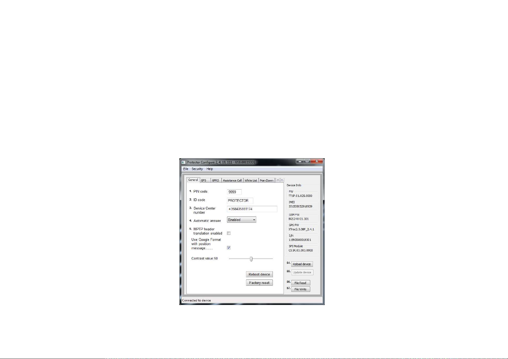
4. General configuration settings
Reboot Device -button will restart the unit and
reload settings from device to Configurator
program. Reboot is needed after uploading
settings to device by Update Device –button.
Factory Reset –button will clear all settings
from the unit and store factory defaults.
PIN Code
PIN code (4 digits) is used to unlock Protector’s
SIM card, unless you are using a SIM card in
which the PIN code request is disabled. Default
value for PIN code is 9999. Replace the value
with your own PIN code, or leave unchanged if
PIN request is disabled in the SIM card. If the
PIN code is defined incorrectly, you won’t be
able to turn on your Protector. After three
failed attempts, the SIM card will be blocked.
If your SIM card gets blocked, you need a
PUK code (8 digits) to open it. Remove the
SIM card from the TWIG device and install it
into a phone compatible with your SIM card.
When trying to open the phone, it will prompt
you for the PUK code. After entering the PUK
code, key in a new PIN code. You can then
install the SIM card back to your TWIG
device. If you fail to key in the correct PUK
code 10 times in a row, your SIM card will be
permanently blocked. If this happens, contact
your network operator to get a new SIM card.
ID
You can define identification for your TWIG
device. This code may contain both numbers
and letters, and it is case sensitive. Default
value for the ID code is: Protector. Currently
this value is not sent in MPTP messages.
Service Center number
Defines the SMS number where generic Mobile
Originated MPTP messages such as low
battery or docking & undocking notifications are
sent. The same number is also authorised to
transmit remote configuration via SMS.
Automatic answer
Allows restricting incoming calls and automatic
answer for incoming calls. As default all
incoming calls are allowed and they are shown
to user as incoming call.
Note that if White List is in use, the
handling of calls or calls and SMSs will
override this setting.
MPTP header translation
Translate Header defines whether special
characters (? and !) in the beginning of SMS
based MPTP messages are replaced by letters
or not. Replacement is necessary in some
mobile phone networks where operator uses
these for their own purposes.
Translate header: OFF ON
Requests: ? Q
Updates: ! E
Default value is OFF.
Page 4
Note that the Translate Header setting needs
to be configured identically in the central
station, whether it is a monitoring server
system or a TWIG Discovery.
Use Google Format with position
messages.
Enables mode where all outgoing messages
are sent as hyperlink. Data fields from the end
of message are in brackets in the end of
hyperlink.
Contrast value
Contrast value slide changes device screen
contrast. The value is unique to each unit and
is pre-programmed in the factory.
Power Saving Mode
Power Saving Mode is available only in some
product versions such as TWIG Asset Locator.
Note that if you use incorrect version of
TWIG Configurator you may find this option
available for units it is not indented for and
this may result in device malfunction.
Power Saving Mode controls how the device
sleeps and wakes up. This substantially affects
the device operating time.
Note that if Power Saving Mode selection is
other than Normal then the GPS_ON and Man
Down functions are disabled.
Normal: Device does not enter “deep sleep”
at all. Device uses timers (such as GPS max
search time, GPS sleep time, GPRS
reconnect interval) to control operation and
current consumption.
Medium/Sensor: Device wakes up after
GPRS Reconnect interval has elapsed, or
whenever it moves (detected movement is
greater than GPS_motion_on Sensitivity
(mG) ). As long as device is awake it is
controlled normally by GPS max search time,
GPS sleep time and GPRS reconnect
interval. If tracking is activated, tracking
update messages are sent only when device
is moving and awake. Whenever movement
stops (detected movement is below
GPS_motion_on Sensitivity (mG) ), device
goes to sleep after 5 minutes.
Heavy/Timer: The device wakes up only to
the Power ON key, or after GPRS Reconnect
interval or active tracking interval has
elapsed.
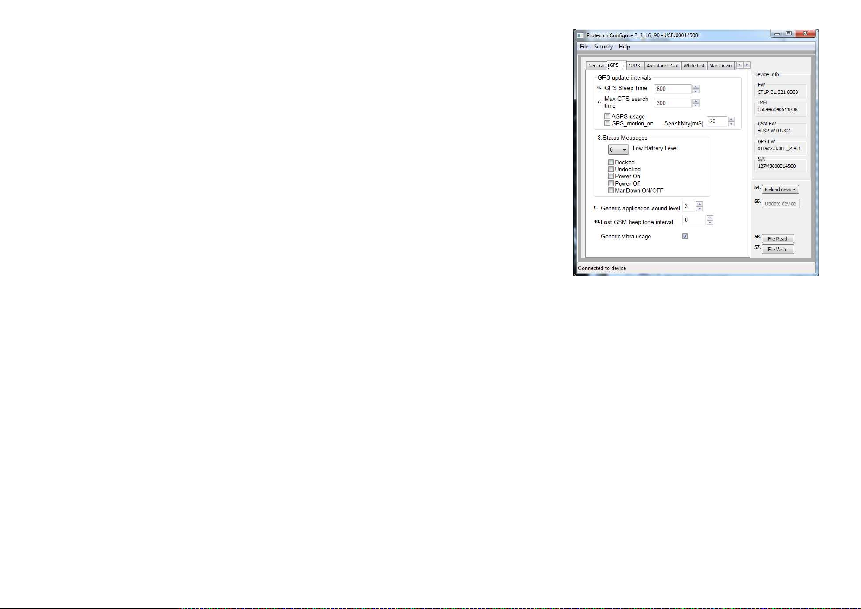
5. GPS & status messaging
settings
GPS sleep time
Defines how frequently GPS is updating
position while not controlled by other
processes like tracking. Time interval can be
set to: 0 - 65535 seconds (18:12:25 hrs).
Default value is 600 (ten minutes). 0 means
that GPS is permanently turned ON.
Max GPS search time
Defines for how long GPS is trying to get a
refreshed position after receiving a position
request. If the refreshed position is not
acquired within that time, device sends position
update using the previously stored last known
position. Valid values for GPS search time are
between: 120 - 600 (seconds). Default value is
300 (five minutes). If the value is low, unit may
not get position at all in poor satellite
conditions. If the time is set long and unit is in
poor satellite conditions it may unnecessarily
increase power consumption and thus
decrease operating time.
AGPS Usage will determine whether AGPS
(Assisted GPS) service is used. If the option is
selected, unit will request assistance data from
supporting server (same server as defined in
Page 5
setting GPRS IP address). Server must support
TWIG AGPS service (For more information
please contact support@twigcom.com).
GPS_motion_on setting defines if the GPS is
controlled by motion sensor. If selected, GPS is
turned off to save battery whenever detected
movement is lower than the value defined in
the Sensitivity field. Note that if this option is
selected, you cannot use Man Down alert
functions.
Status messages
Define if the TWIG device transmits a message
to Service Center informing of various events.
Device alerts when its battery level declines to
20, 40 or 60 percentage of full battery charge.
Setting the value to 0 deactivates alarm.
Default value is 0.
Note that battery levels can vary substantially
when using the device, particularly when using
timer functions. This may cause wrong or
repeating Low Battery alarms.
Docked message is sent when TWIG Protector
is placed in charging station CTA81 and
Undocked message when picking up the
device from charging station.
Power ON message is sent when device is
started and Power Off message when user
turns off the device or it turns itself off due to
low battery.
Note that if docking/undocking or power
on/power off happen within 1 minute the
latter status message may be lost.
ManDown ON/OFF sends message if user
toggles ManDown function. Permission for
user to toggle can be set in Man Down
settings.
Generic application sound level
Defines the volume level that is used to play
warning, notification and incoming call tones.
Value can be set from 1 to 5, or if value 0 is
used tones are not used at all. Default value
is 3.
Lost GSM beep tone interval.
Defines the interval for BEEP tone in case
the roaming GSM network is lost. You can
set the interval between 20 - 65534 seconds.
If set to 0, the tone will never be played.
Default value is 0.
Generic Vibra Usage defines whether
vibrator is used on generic notifications. A
separate setting exists for vibrator use in
Emergency functions.
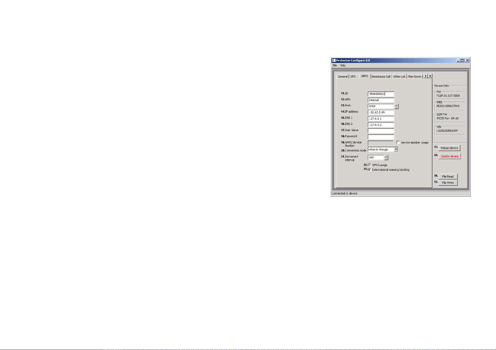
6. GPRS settings
GPRS settings can be programmed remotely
from the central station over MPTP SMS
messages (as TWIG WebFinder SP does) or
they can be programmed manually.
When GPRS settings have been programmed
remotely, care must be taken not to interfere
with remote settings when using TWIG
Configurator.
ID
User ID is a number used in identifying your
phone in GPRS server. Typically this is the
phone number of your TWIG device.
Access Point Name APN
The Access Point Name (APN) used for GPRS
communication.
Define the entire APN value in the field.
Typically GSM operators allow the APN to be
left empty or replaced with “internet”. You can
get the correct APN from your GSM operator.
Page 6

GPRS server port number
A port number is required for GPRS
communication. The value can be set between
0 - 65535. As default, TWIG Web Finder
service port 8484 is used. In older firmware the
default is locked. Contact TWIG Support if you
need to change it.
GPRS IP address/domain
IP address that is used in GPRS
communication. As default, TWIG Web Finder
IP address 192.83.5.99 is used. In older
firmware the default is locked. Contact TWIG
Support if you need to change it.
TCP90EU with SW later than
CT1?.010.021.0000 supports also domain
name instead of IP address allowing flexibility.
GPRS DNS 1-2
Some GPRS networks require that primary
domain name server (DNS1) is specified.
Define the DNS as an IP address. Maximum
length for DNS1 name is 16 characters. Default
value for DNS1 is 127.0.0.1 and for DNS2
127.0.0.2.
GPRS user name
If your operator requires a user name for
GPRS login, define the name here.
GPRS password
If your operator requires a password for
GPRS log-in, define the word here.
Backup SMS number
Phone number where MPTP messages are
sent as SMS, in case GPRS connection is
not available, and Use SMS Backup if no
GPRS is activated.
Some functionality changes or limitations
may apply. For example, real-time tracking
(TRR) is not possible via SMS.
Note that activating Backup SMS may
result in high SMS transmission costs.
GPRS Connection mode
Defines how the GPRS connection to
server is kept active:
0 = only reconnect mode is used
1 = always on when connected to charger,
else reconnect mode
2 = always on
Default setting = 1
Note that if you define 2 (always on) it may
prevent device from sleeping or using timer
functions. It also increases the power
consumption significantly and thus reduces
battery life.
Reconnect interval
Reconnect interval is used in reconnect
mode. The device sends reconnect
messages to server to check the server
status and incoming messages possibly
pending in server. You can set the sending
interval for reconnect messages in seconds.
Default value 600 s (ten minutes).
Note that if the value is set to 0 (zero),
reconnect interval is not in use.
Reconnect Interval value is also used in timer
based operations defined in Power Saving
options.
GPRS usage
Defines if GPRS is used or not.
1 = enabled
0 = disabled
Default setting = 0
Note that also user ID must be defined to use
GPRS telematics.
GPRS international roaming blocking
If International Roaming Block is selected,
GPRS connection is disabled when roaming
outside home network. If not selected, GPRS
connection is available also during international
roaming.
Default value for International Roaming Block
is inactive. The value is checked every time
when creating GPRS connection.
Note that allowing GPRS data in roaming
networks may result in very high data costs
charged by your mobile operator. Unit may
also roam in your own country close to
country boarders.
Page 7

7. Assistance call
Assistance numbers
Here you define the action when the numeric
keys on the TWIG Protector are pressed. If you
program only one number per button the action
is either call or MPTP assistance (!ASS) SMS
depending on which is configured.
If both numbers are defined both actions are
done.
In Protector Easy only first pair of numbers is
used to trigger call/SMS with the Green SEND
key.
In devices where there is no function e.g. Dog
Locator or Asset Locator the fields have no
value.
Programming “GPRS” as the SMS number
the !ASS message will be sent over GPRS
telematics.
8. White list (WL)
White List is defining authorization of
incoming SMS and/or voice call to perform
automatic actions. If White List
authorization is in use, the authorised
numbers must be listed, otherwise messages
and calls will be rejected.
WL Usage defines to which functions and
how the White List is applied.
If disabled, White List is not used for
authorising numbers. If SMS is selected, all
incoming MPTP SMS messages are
screened. If CALL is selected, all incoming
calls are screened. If SMS and CALL is
selected, incoming MPTP SMS and calls are
screened.
Each White List number can be individually
authorises to send location request and/or
tracking activation SMS by checking the
respective boxes.
Voice calls from each White List number
can be individually screened.
Blocked: calls from this number are blocked
Allowed: calls from this number are allowed to
ring
Auto answer: calls from this number are
automatically answered
HF answer: calls from this number are
automatically answered in hands-free (Speaker
Phone) mode.
Note that Speaker Phone mode is very loud
and its use must be carefully considered.
Automatic Answer Setting in General
Settings is overridden by White List when
CALL or CALL and SMS is selected. A mix
of allowed and blocked numbers can be
defined, but if list has only blocked calls it
blocks all calls.
GPRS messaging is not controlled by White
List but by GPRS settings.
Note that regardless of White List settings the
device can be reset to factory defaults by
specific over-the-air commands (SMS or
GPRS) when device particulars are known.
Page 8

9. Man Down Alert
Note that if the GPS_motion_on setting is
used, Man Down Alert can not be used and
settings are greyed out.
Alerts when
Set the orientation which causes the sensor to
launch Twig SOS.
When Horizontal is selected, Twig SOS is
launched when device main axis orientation
deviates from absolute upright position by more
than Man Down Angle (in degrees).
When Vertical is selected, Twig SOS is
launched when device beam axis orientation
deviates from absolute upright position more
than Man Down Angle (in degrees).
Appendix Man Down Angle on last page
illustrates device orientations for alert and no
alert.
Default value is Horizontal.
Man Down Alert criteria combines
Vertical/Horizontal detection with detection of
movement. If the preferred alarm criteria is
tilt angle only, then set Motion Sensitivity
(mG) to 999 (Alarm will be triggered by tilt
angle as long as movement remains below 1
G).
When Movement is selected, only detected
movement (acceleration) is monitored and
device orientation does not affect launching
of alert.
No Alarm duration:
When the sensor detects alarm-triggering
status (vertical/horizontal/no movement), this
setting defines a waiting time during which
the sensor is waiting for the normal status to
be restored, before actually triggering the
pre-alarm and finally alarm. This is useful to
prevent unnecessary alarms for example in
cases where the user has fallen down or sits
down but is otherwise fine. No Alarm
duration can be set to 1 - 65535 seconds.
Default value is 30 seconds.
Pre-Alarm duration:
Once Man Down sensor has detected an
alarm-triggering condition and the No Alarm
period has passed, device enters Pre-Alarm
period. During Pre-Alarm the user is alerted by
sound and vibration (according to sound and
vibration settings in SOS settings 2). When
Pre-Alarm period is over, and normal
orientation/movement has not been restored,
Twig SOS is launched. Pre-Alarm duration can
be set to 1 - 65535 seconds. Default value is
30 seconds.
Motion sensitivity:
This setting defines the amount of movement
(acceleration) needed to indicate that the
device is moving. Value can be set between 1
– 999 mG. Default value is 100 mG.
Man Down Angle
Defines the tilt angle (in degrees) the device
must tilt, before its orientation is deemed to
change from Vertical to Horizontal. Default
value is 45 degrees.
Normal status delay
Normal Status Delay defines how long the
device needs to be back in the normal
orientation/movement before normal status is
restored. Normal Status Delay is useful to
prevent restoring the normal status and
cancelling Twig SOS alert by accident. Normal
Status Delay can be set 1 - 65535 seconds.
Default value is 1 second.
Man Down sensor on/off
Page 9

Defines if the Man Down Alert is active or
inactive.
Man Down sensor usage mode
Defines the mode how MDA is controlled.
ON = Man Down is always on when Protector
is turned on.
Enabled on = MDA is turned on when
Protector is turned on, but user can toggle
mode off/on with key 4.
Enabled off = MDA is not turned on when
Protector is turned on, but user can toggle
mode on/off with key 4.
10. Twig SOS settings
Phone Number and Name
Define SMS numbers to which alert MPTP
messages are sent and voice numbers to
which alert voice calls are made. Name is
only for reference and not shown on screen.
(Note that lines 1-10 on top correspond to
lines 1-5 and 6-10 at bottom.)
Event Type defines call or SMS. Event
Retries defines how many times a failed
event is retried before moving to next one.
Event Group is not used.
All SMSs are sent first, at the same time as
the first call (if any) is being made.
If GPRS connection to central station is
defined, alarm MPTP message is sent over
GPRS before making call. This does not
delay the call more than a few seconds. If
GPRS connection is not possible, call only
will be made.
Because SMS transmission is in many
circumstances more reliable than GPRS, it is
recommendable to always define SMS for
SOS message.
As soon as a call in the SOS event list is
answered the cycle will stop making further
calls, if EMG Call Continue (in SOS settings
2) is off. An answering machine will also stop
making further calls. If EMG Call Continue is
on, all calls in the SOS list will be made.
Note that to enable the GPRS Emergency
Message the value “GPRS” ( without “”) must
be written to the first “phone number” field.
11. Twig SOS Settings 2
MPTP SOS Text
Defines the text in EMG Message Data Field
when TWIG SOS is initiated by SOS key.
Default value is SOS BUTTON.
MPTP MD Text:
Defines the text in EMG Message Data Field
when TWIG SOS is initiated by Man Down
Alert. Default value is MAN DOWN ALERT.
MPTP RF SOS Text:
Page 10

Defines the text in EMG message data field
when TWIG SOS is initiated by wireless alert
button (TWIG Button).
The three text fields above are 15 characters
long maximum. They can only have characters
0-9, A-Z and a-z. No special characters are
allowed.
Wireless alert unit serial number
Defines serial number of the Wireless Alert button paired with the device. Maximum 5
buttons can be defined.
When TWIG SOS is initiated by Wireless Alert button the EMG message includes text field
(MPTP RF SOS Text) followed by wireless
alert button index number (1 – 5).
Click on the Get RF ID -button to activate
learning mode. Then press the Wireless Alert button. Indicator on the button unit will first light
red and turn green once paired.
To delete a Wireless Alert -button, clear the
corresponding Wireless Alert unit serial number
box and press enter. Then update device.
Vibrator enabled
Define if vibrator is used in conjunction with
TWIG SOS. Device will vibrate when button is
pressed and in case of Man Down Alert also
during Pre-Alarm. Default is ON.
Display enabled
Defines if TWIG SOS is sent without showing
actions on device screen. If disabled, only a
small icon in the info line on top of screen
indicates ongoing alert. This allows discrete
or hidden TWIG SOS. Default is ON.
Message resending
Defines if the alarm message is resent if
GPS position is refreshed during emergency
cycle. Default is ON.
Post emergency usage:
Defines if Post Emergency Mode is active.
This for example keeps GPRS connection
on, blocks incoming calls and turns on post
emergency beep to enable locating the user.
If Post Emergency Mode is used another
alarm can not be made until emergency
mode is ended with RED END key. Default is
ON.
Power off disabled
Blocks the user from turning off the unit with
power key. Default is OFF.
EMG call continue
Forces the emergency cycle to process all
calls even if the preceding call is successful.
I.e. all calls must be successfully made
before stopping the emergency cycle.
Power up self-test
Defines the self-test for accessories, alarm
button and Man Down. Can be used with or
without requirement of ACK from ARC.
Power Off when docked
Defines if units is sending a request to power
off when set to cradle. Power Off is sent from
ERC.
Emergency number text
Defines the text for prompting user to call
network emergency number, for example when
no SIM card is inserted or no roaming network
is available. Default text is 112.
Note that this is text only and does not
affect dialling. Call will be made to public
emergency service. No position is sent.
Post Emergency beep
Defines the time interval between “locate me”
beeps. Range is 20 - 300 seconds. Default is 0
which means the beep is disabled.
SOS Activation mode
Selects how the TWIG SOS button is used to
activate emergency cycle, between one long
press or two short presses.
Activation Method Timeout defines how long
the SOS button needs to be pressed or within
what time it needs to be pressed twice.
If SOS Activation mode is set as disabled, the
button cannot be used.
Event Start delay
Page 11

Defines a delay used between events in TWIG
SOS cycle. Depending on the network this
delay may need to be substantial since network
may reject calls made in fast sequence. If there
are only SMS numbers in the SOS cycle the
delay can typically be shorter.
Full SOS Cycles
Defines the amount of full TWIG SOS event
cycles to be done. Range is 1 – 5. Default is 1.
Call timeout
Defines the timeout to skip to next event on
SOS list if no answer from B-subscriber.
Activation method timeout
Defines for how long the SOS button needs to
be pressed or within what time it needs to be
pressed twice. Default is 5 seconds.
Cancellation period
Defines the period (0 - 20 seconds) when the
TWIG SOS can still be cancelled if activated
from TWIG SOS button. Default is 0 which
disables the cancellation possibility.
END Key Timeout
Defines if the TWIG SOS can be ended once
started. 0 means it can only be ended from
remote center by hanging up the call. Default is
1.
SOS tones sound level
Defines the warning and indication sound
level used when starting TWIG SOS. Same
setting is used for Pre-Alarm of Man Down
Alert.
Speaker level
Defines the device speaker level when
making a TWIG SOS call.
Note that levels 4 and 5 are on Speaker
Phone level and are too loud for normal
phone use.
EMG ACK timeout
Defines the time how long device will wait for
acknowledgement from EMG message
recipient before proceeding to next number
in the list.
12. Amber Alert a.k.a.
Condition Check
Mode
Defines the operating mode of Amber Alert.
Mode can be OFF, Local or Interactive. In
Local mode no ACK is required to turn on
the AA/CC. In Interactive mode ACK is
required from activation number to turn on
the mode.
Phone number type
Defines if SMS or voice call is used to turn
on the AA/CC mode.
Activation number
Defines the number where the activation
SMS/call is sent/made.
Deactivation number
Defines the number where the deactivation
SMS call is sent/made.
PreAlarm time
Defines the timer value that is used to make
prealarm when the AA/CC interval is met.
During the PreAlarm user can either reset or
turn off the AA/CC mode. If the mode is
interactive ACK must be received from the
Activation number before timer expires.
SOS Text
Page 12

Defines the MPTP message text, that is send
in !EMG message when Emergency Cycle is
launched by AA/CC function.
13. Indoor Module
Indoor Module Power ON defines if the
assembled module is turned on for use. Please
note, that the module is not in all devices and it
may also be deactivated so, that it can not be
turned on. Please consult Twig Com Support if
you think the module should be configurable,
but there is no function.
Beacon low battery warning forwarding
defines if the low battery information is sent
from device to backend service. If the setting is
ON, the message is sent when device registers
new beacon with low battery status. Low
battery message is sent only once. When the
device receives from same Beacon Low
Battery Cleared message the status of that
Beacon low battery is reset.
RF tag enabled activates Protector to listen
messages sent by RF Twig Tag.
Beacon search time defines the maximum
time the Beacon signals are monitored.
SDR module sleep time. If the value is set
to 0, the module is on all the time. Note that it
effects the power consumption.
14. Internal MPTP command
Internal MPTP Command allows
programming as macros executed in the
device same kind of commands that typically
are sent via SMS or GPRS, such as tracking
or position request.
Internal MPTP commands can be run
automatically on every start up or when unit
shifts from Emergency to Post Emergency
mode.
As an example, automatic tracking could be
started when Emergency cycle is passed.
The use of this mode requires that Post
Emergency is used in SOS Settings 2.
If the usage mode is OFF the command will
be processed automatically if mode is
changed and the condition next time met.
Usage field defines the condition when the
command is executed.
Phone number is the recipient of SMS based
MPTP message. MPTP command is the actual
command that is processed.
15. Updating software
New devices of type TCP90EU have separate
PC program for updating the firmware. Please
check www.twigcom.com.
Updating firmware of old devices of type
TGP81EU is done under the Firmware tab.
Device firmware is embedded in the TWIG
Configurator program from version 1.2
onwards. If you have older version, please
download the latest. Update your existing
TWIG Protector software by clicking on the
Page 13

Burn -button. A progress bar displays the
status of the updating process.
16. Saving data file
You can save device settings from TWIG
Configurator program to a PC file as well as
read device settings files from PC to TWIG
Configurator. As a default settings file is stored
in the same directory where the actual TWIG
Configurator program executable is stored. The
default settings data file name is
configure_save.bin. This file is used when the
program is started and File read button is
pressed.
By selecting File/Data FileName you can
change the settings data file name. For
example: Protector_settings_customer_A.bin.
Once defined, the same Data File will be
used during one session, and any settings
stored with File Write are stored there.
Pressing File Read will bring the settings
from that current Data File to program value
fields and they can be then programmed to
the TWIG device.
Note that you may need to change a value
before the Update device button becomes
active.
17. Firmware versions
Different device types have different types of
Firmware. The first 4 characters in the
firmware file name define the type. Second
and third set of numbers are version
numbers and last set is custom version
identifier.
A device cannot normally be programmed
with firmware type different from the one
already in the device. If you have a need to
do so for example for testing please contact
Twig Com Support at support@twigcom.com
or +358 40 510 5058.
CG/T1P = TWIG Protector
CG/T1E = TWIG Protector Easy
CG/T1A = TWIG Asset Locator
CG/T1D = TWIG Dog Locator
Page 14

Appendix A: Man Down Angles
illustrated
Tilt angle e.g 45°
Allowed orientation in green.
Both on top and botto m. If tilt ed
more th an 135 deg rees, agai n in
allowed orientation. Alarm when
in RED area
NOTE, that also movement
condition must be met
Alerts when horizontal
No alert
Alert
Alerts when vertical
Alert
Tilt angle e.g 45°
Allowed orien tation in green .
Both on top and bottom. If tilted
more than 135 deg rees, again in
allowed orientation. Alarm when
in RED area
NOTE, that also movement
condition must be met
No alert
 Loading...