

Page 1

TRACKBOX INSTALLATION GUIDE
STRUCTURE OF THE DEVICE
Location, temperature and use of the device set some restrictions for
selecting the model. Both models are fixed installations using same
type of hardware platform and front panel, although the accessory
module might slightly differ depending on the model.
Model descriptions
STANDARD MODEL: BASIC TRACKING FEATURES
•In addition to basic tracking functions, this model offers capability
for GSM and NMEA data transfer through the configuration port.
(Local data transfer requires the BwTrackbox cable, which is an
accessory and sold separately.)
•Equipped with continuing power supply: Contains a built-in
charger with 10-30VDC input power supply and a Li-Ion battery.
•Li-Ion batteries available for the device are: A standard battery 1700
mAh or a backup battery 650mAh. (Li-Ion 650, 900, 1200 mAh are
also approved, but might not be provided by the manufacturer)
•Possibility to use an external Pb battery (12V), as well. Pb battery
needs a separate charger (NOTE: Neither one is provided by the
manufacturer).
I/O MODEL: ADVANCED TRACKING FEATURES
Otherwise the same as the standard model, but additionally the I/O
model contains full I/O functionality and an Event log.
•The I/O functionality comes with 9+1 digital inputs, 8 digital outputs, and 4 analogue inputs. Inputs and outputs are for integrating
special functions with the device. Such functions could be, e.g. a car
immobilization system, an alarm system, registration of opened
doors/liquid level/temperature changes and so on.
•Event log is used for storing positions and I/O events, which can be
recalled afterwards and even remotely by making a CSD-data call.
Pins available for the I/O model
Function PCB Function PCB
Digital Input D_in1 Digital Output D_out1
Digital Input D_in2 Digital Output D_out2
Digital Input D_in3 Digital Output D_out3
Digital Input D_in4 Digital Output D_out4
Digital Input D_in5 Digital Output D_out5
Digital Input D_in6 Digital Output D_out6
Digital Input D_in7 Digital Output D_out7
Digital Input D_in8 Digital Output D_out8
Digital Input D_in9 Ground GND
Emergency EMG Ground GND
Analog Input A_in1 Ground GND
Analog Input A_in2 Ground GND
Analog Input A_in3 Ground GND
Analog Input A_in4 Ground GND
Vin 10-32 VDC Vin Vin 10-32 VDC Vin
TRACKBOX (outer structure)
Plug for the
external
GPS
antenna
LEDS:
•GSM (red)
•GPS (yellow)
•Battery (green)
Battery
release
catch
Battery
Inlet for the
BWTrackbox
cable
Flip cover GPS
antenna
GSM antenna
Power on/off key
Screw
holes (4
pcs) for
mounting
the device
Built-in
microphone
Inlets for
I/O cables
Accessory module (inner structure)
DATA PORT 1:
•Digital outputs: 4 pcs
•Digital inputs: 5 pcs
•Analogue inputs: 2 pcs
•Ground terminals: 3 pcs
•Voltage input
NOTE FOR
PROGRAMMERS:
When programming the
I/O processor (firmware
update of I/O processor), the pin header
needs to be placed into
narrow holes (jumpers).
DATA PORT 2:
•Digital outputs: 4 pcs
•Digital Emergency input
•Digital inputs: 4 pcs
•Analogue inputs: 2 pcs
• Gr ou nd te rmina ls: 3 pcs
•Voltage input
CONFIGURATION
PORT:
For local GSM and
NMEA data transfer
via the BWTrackbox
cable
DIGITAL INPUTS
An external, wired input switch can be connected to the device. Total number of digital input pins is 9+1. One input is reserved for
emergency use. The other inputs can be used for logging or sending
status messages. Inputs can be used concurrently with outputs.
Grounding activates input. After grounding, the device will get a signal. Grounding of the input pin1 sends the status message1 to the
service center number while grounding of the input pin2 sends the
status message2 etc. If configured, grounding of the input pin will
store the event and position on Event log, instead of sending the
message. Logging can be used concurrently with sending, as well.
Digital inputs can also be configured to have a response time to ignore short pulses. A value for response time can be set, e.g. to 2 seconds, excluding the time needed for an SMS transfer.
Digital input pins are protected against AC/DC overvoltage and current.
•Max. voltage: 30 VDC
•Impedance: High.
ANALOGUE INPUTS
Device includes 4 analogue inputs that could work concurrently with
other pins. Analogue inputs can be used for e.g. measuring liquid
level changes. Threshold values for high and low can be set to trigger alarm.
•Voltage: 0 - 10 VDC.
DIGITAL OUTPUTS
An external device can be connected to an output pin. Device includes 8 outputs that could work concurrently with inputs.
Sending an MPTP command to the device will activate or deactivate
the pin. Additionally a short pulse can be generated to output for indicating and logging rotation.
•Max. voltage: 30 VDC
•Max. current: 300 mA
SPECIAL NOTES CONCERNING OUTPUTS AND
GROUNDS:
•Use separate Ground wires for power and outputs.
•Never connect more than 3 Outputs with 1 Ground wire.
Page 2
TRACKBOX INSTALLATION GUIDE
MECHANICS AND ENVIRONMENTAL
EFFECTS
Assembling the device
NOTE: First make all the internal connections (see the picture below). Only after the assembling is completed, the battery and
the external voltage input (power cord) can be connected to
the device.
B: CONNECTING
PINS
The I/O cable
contains conducting wires (3) for
pins.
Stick a wire into a
pin hollow (4) and
fasten it by screwing on the top of
4
5
the corresponding terminal block
(5).
-Standard model:
3
Connect the
ground (e.g. black
wire, - ), and
voltage input (e.g.
red wire, +).
-I/O model:
In addition to
grounds and voltage inputs, con-
2
nect the desired
I/O pins.
I/O cables
SCREWING THE BACK COVER
Screw holes (6 pcs) for
fixing the back cover
O-ring
seal
You may screw the back cover back in
after the device is completely assembled and the initial configuration
(made by Benewin software) is done.
For more on configuring the device by
Benewin, see The Trackbox operating
instructions.
When screwing the back cover to the
device, use the O-ring seals for improving splash-proofing.
C: COMPLETING INTERNAL CONNECTIONS
After the conducting
wires are connected
6
to terminal blocks,
the wires left
unconnected must
be insulated, e.g. by
cutting out the
peeled ends of the
wires, or fastening
these ends with a
piece of firm tape(6).
A: CONNECTING
I/O CABLES
Pierce a hole in the
I/O cable inlet (1).
NOTE: If you intend
to use only one I/O
cable, leave the other inlet intact.
Direct the I/O cable
through the inlet and
place the cable
clamp (2) in place.
1
Installation
MOUNTING
1. Place the flat back cover towards a desired surface, e.g. a wall.
2. Mount the device by fixing and securing screws through the
screw holes. Alternatively the device can be mounted by using
a bush ring installation, for example in a roof installation.
3. For improving splash-proofing, it is recommended to install
the device to an upright position with the I/O cables directing
downwards.
The front panel includes a battery and “a flip cover” GPS antenna.
The GPS antenna can be covered with plastic, fiber glass or
clothes, but NOT with metal.
SIGHT
The GPS antenna must have an unobstructed view to satellites at any time. In marginal conditions an external GPS antenna, possibly even a GSM antenna, must be installed.
Temperature ranges
•Usage: -20 to +55 °C with a standard Li-Ion battery
(both models).
•Charging: Standard Li-Ion battery must not be charged
below 0 °C.
SPECIAL NOTES CONCERNING BATTERIES
At temperatures below -25 °C, standard Li-Ion batteries will not
supply power and the device (using standard Li-Ion batteries) cannot be used. Upon warming up, the battery will function properly
again.
If the device is frequently used below 0 °C, a standard Li-Ion battery must be replaced with a special backup battery including a
built-in switch, which controls temperature and prevents charging
whenever necessary.
Mechanical durability
The device is not categorized for damp conditions. In case the device will be permanently used in such conditions, it must be provided with separate housing, suitable for antennas, as well.
However, overall dust and water protection of the device can be
improved considerably by using o-ring seals with screws, and inserting the rubber seal of the battery in place correctly.
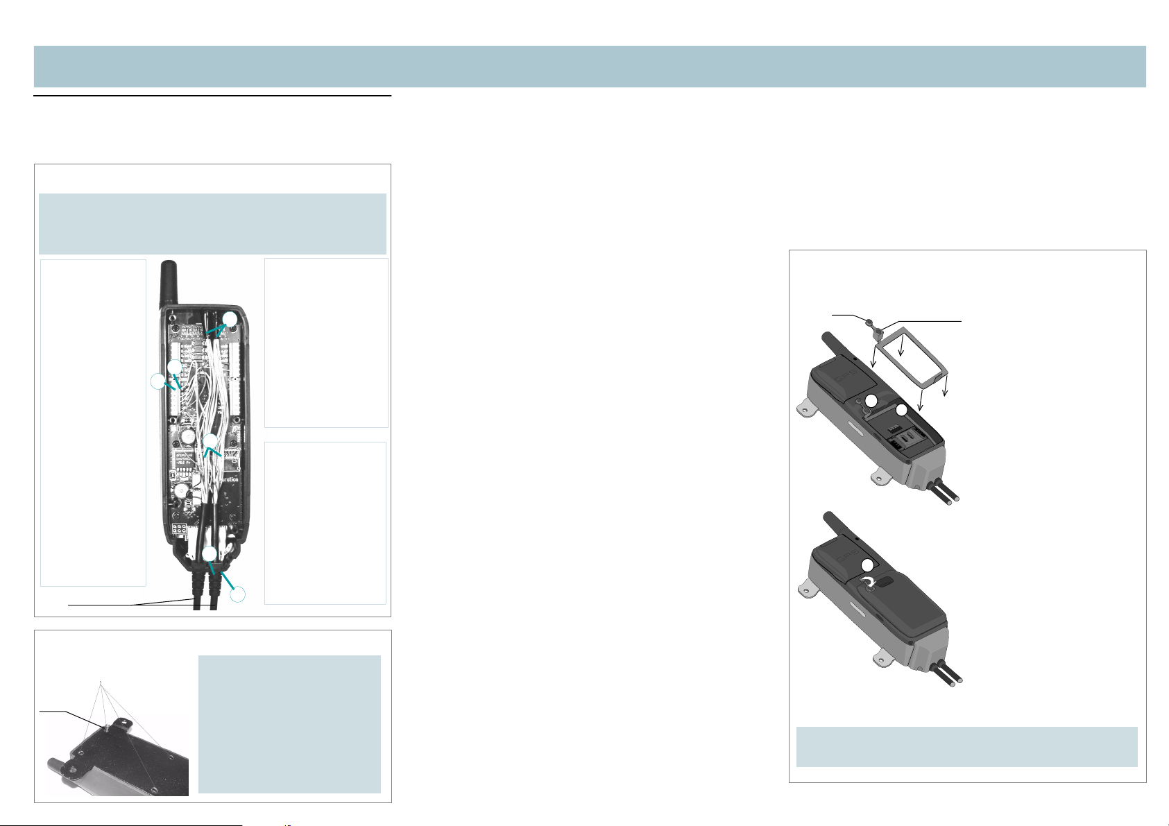
INSERTING THE BATTERY AND RUBBER SEAL
Cap
Removing the battery: Push the release catch downwards and
pull the battery carefully away from the device.
2.
3.
Rubber tab
1.
1. Place the rubber seal so that it
lies at the bottom of the battery hole (see the picture).
2. Fit the rubber tab into the recess in the upper left corner.
3. In case an external GPS antenna is NOT plugged in, lift the
cap on the top of the rubber
tab. This needs to be done for
improving the protection
against dust and water.
4. Fit the battery in place. The
idea is that the battery will be
securely fastened in the battery hole.
5. Push the battery into the device until it locks in place, and
lift the release catch into an
upright position (a click
sound is heard).
6. In case the inlet for the
BWTrackbox cable is pierced,
but the BWTrackbox cable is
not in continuous use, the
hole needs to be covered with
some waterproof material,
such as a piece of firm tape or
silicon.
Page 3

TRACKBOX INSTALLATION GUIDE
USER INTERFACE
Invisible mode
The device can be configured to work in an invisible mode to make it
more difficult to detect. Under the circumstances only some of the basic LED patterns are displayed indicating events, such as an incorrect
pin, power up/down.
In the invisible mode, the LED´s are not lit, e.g. in these cases: an incoming call, an active call, an incoming MPTP message, an outgoing
position message, an outgoing battery low message, an outgoing
emergency message.
Indicator LEDs
Symbol Meaning
!
"
#
$
...
On for 1 second
Off for 1 second
On for half a second
Off for half a second
Star ts ov er f rom t he b eginn ing of th e patte rn
GPS LED (yellow) shows GPS status
!... (constantly on)
#$"... (in sequence of 2 seconds)
!"... (in sequence of 2 seconds)
"... (constantly off)
! (lit for 3 seconds)
- NOTE: The LED pattern cannot be seen, if the LEDs are
already lit for some other reason at the time of this event.
GSM LED (red) shows GSM status
!... (constantly on)
"... (constantly off)
!"... (in sequence of 2 seconds)
#$#$#$#$".. (in sequence of 6 seconds)
!... (flashes in every 5 seconds, if the LED is not already lit
for some other reason)
! $#"!$#"!$#...
#$".. (2 sec. sequence)
Val id fix
Sleeping (zzz)
Searching/Locking
Off
A valid position fix is finally
acquired after searching for a
while.
Network available
Off
Searching
No network
Power is on
Active call
Invalid SIM
All the LEDs are lit in union
and show
!"#$!"#$!"#
(once)
#"#"#"
!"!"#"#"#
(once)
#$...
! ! (once)
#$... (five times)
Answers an incoming call.
- NOTE: In order to work, a valid SIM card
must be inserted, and the device must be
turned on, and the auto answer setting must
be turned on.
An MPTP message is received and accepted.
- NOTE: In order to work, a valid SIM card
must be inserted, and the device must be
turned on.
Incorrect PIN. It causes the device to pow erdown.
Sending of a status message
succeeded.
Sending of a status message failed.
Battery LED (green) shows Battery status
!... (constantly on)
! ! ! !#$#$... (6 sec. sequence)
! ! !#$#$#$... (6 sec. sequence)
! !#$#$#$#$... (6 sec. sequence)
#$#$#$#$".. (5 sec. sequence)
- NOTE: The pattern cannot be seen, if the LEDs are lit for
some other reason at the time of this event, or if less than 5
minutes has passed since the event was last invoked.
!"... (2 sec. sequence) The LED flashes current battery
status in turns with charging.
Status/Action
4/4 (battery is full)
3/4
2/4
1/4
0/4 (battery is low)
Charging.
Keys
Side key Function Procedure
/
(press and hold
down for a few
seconds)
/ (press and
hold down
for a few
seconds)
/ (press briefly)
FOR MORE INFORMATION, DETAILED DESCRIPTIONS AND
FUNCTIONALITY OF THE DEVICE, SEE THE TRACKBOX
OPERATING INSTRUCTION S.
Publication number: YZ2651-1
All rights reserved. © Benefon Oyj, 2003.
Power-up The device is turned on. All the LEDs are lit. The device
Power-down The device is turned off.
Indicator refresh Idle mode is entered. All the LEDs will start to show their
sends a message via the configuration port to inform a
possibly attached external device of the power-up. An
automatic PIN entry and a removal of all short messages found on SIM will take place.
- NOTE: For the automatic PIN entry, the PIN code must
be pre-programmed into the device.
All the LEDs are lit.
current status.
 Loading...