

Page 1
© Benefon Oyj, 2003.
BENEFON
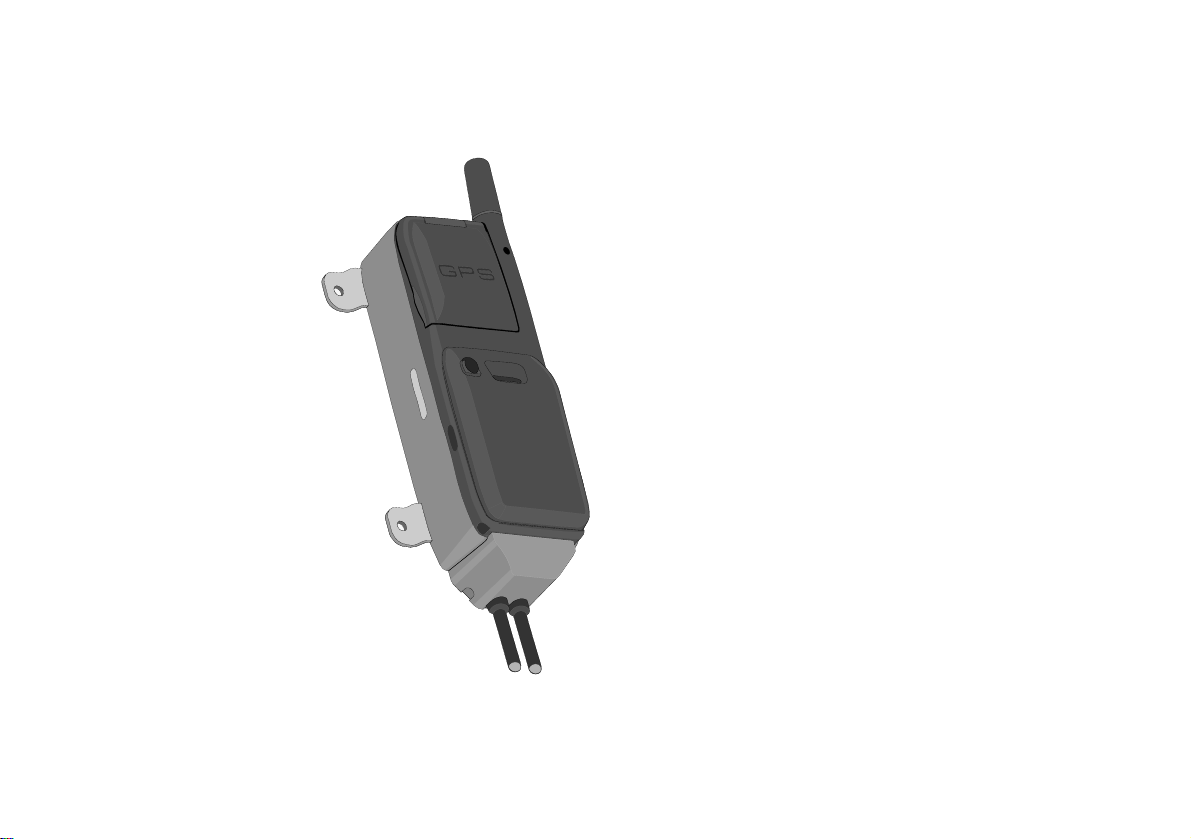
TRACKBOX
Operating
Instructions
Publication number: YZ2650-0 All rights reserved.
Page 2
LANGUAGE
Spanish Mediante el presente documento, Benefon declara que este teléfono móvil, del tipo TGP78EB, satisface los requisitos
Danish Benefon Oyj erklærer herved, at denne mobiltelefon af typen TGP78EB er i overensstemmelse med de væsentlige
German Hiermit erklärt Benefon Oyj, daß dieses Mobiltelefon vom Typ TGP78EB die wesentlichen Anforderungen und andere
Greek Με το παρ όν, η Benefon Oyj δηλώνει ότι αυτό το κινητό τηλέφωνο, τύπου TGP78EB, συµµορφώνεται µε τις ουσ ιώδεις
English Hereby, Benefon Oyj declares that this mobile phone, type TGP78EB, is in compliance with the essential
French Benefon Oyj déclare par les présentes que ce téléphone mobile, de type TGP78EB, est conforme aux exigences
Italian Benefon Oyj dichiara che questo modello di telefono cellulare, tipo TGP78EB, risponde alle principali specifiche e
Dutch Bij deze verklaart Benefon Oyj dat deze mobiele telefoon, type TGP78EB, voldoet aan de voornaamste eisen en
Portuguese A Benefon Oyj declara pela presente que este telemóvel, do tipo TGP78EB, está em conformidade com os requisitos
Finnish Benefon Oyj vakuuttaa, että tämä matkapuhelin, tyyppiä TGP78EB, on direktiivin 1999/5/EC olennaisten vaatimusten ja muiden
Swedish Härmed förklarar Benefon Oyj att denna mobiltelefon, typ TGP78EB, överenstämmer med de grundläggande kraven
Information in this manual is subject to change without notice. BENEFON
reserves the right to change or improve their products and to make
changes in the content without obligation to notify any person or
organization of such changes or improvements. BENEFON is not
responsible for any loss of data, income or any consequential damage
whatsoever caused.
esenciales y todas las demás disposiciones pertinentes de la Directiva 1999/5/EC.
krav og andre relevante betemmelser i Directive 1999/5/EC.
relevante Bestimmungen der Richtlinie 1999/5/EC erfüllt.
απαιτήσεις και άλλους σχετικούς όρους της Οδη γίας 1999/5/EC.
requirements and other relevant provisions of Directive 1999/5/EC.
essentielles et aux dispositions correspondantes de la Directive européenne 1999/5/EC.
misure previste dalla Direttiva 1999/5/EC.
andere relevante voorwaarden van Richtlijn 1999/5/EC.
essenciais e outras disposições relevantes da Directiva 1999/5/EC.
asianomaisten määräysten mukainen
och andra relevanta bestämmelser i Direktiv 1999/5/EC.
DECLARATION OF CONFORMITY
Manufacturer: Benefon Oyj, P.O. Box 84,
24101 Salo, Finland
Web site: www.benefon.com
2
Page 3

CONTENTS
PART A: CONFIGURING SETTINGS FOR THE
TRACKBOX ............................................................7
MPTP MESSAGES AND
REMOTE CONFIGURATION (OTA)...................................7
THE BENEWIN TRACKBOX SOFTWARE.........................7
Connecting the Trackbox to the
Benewin software.......................................................8
THE CONFIGURATION PORT................. ............................... ... .. ......... 8
Loading settings from the Trackbox
to the software............................................................9
Saving settings in a computer disk
(working off-line) ........................................................10
Transferring settings from the
software to the Trackbox ...........................................10
Disconnecting the Trackbox
from the software........................................................11
SHORT MESSAGES..........................................................11
Reading and editing existing messages...................11
Deleting a short message ..........................................11
Writing and sending a short message......................12
PHONE BOOKS.................................................................13
Editing and adding an entry.......................................13
Deleting entries...........................................................13
Arranging entries........................................................13
Moving and copying entries ......................................14
USER SETTINGS...............................................................14
Phone time and date ...................................................14
Activity timer...............................................................14
SETTING THE ACTIVITY TIMER........... .. .. ... ................................ .. ...... 15
Message settings........................................................15
SMS SERVICE NUMBER...................................................................... 15
MESSAGE TYPE................................................................................... 16
MESSAGE VALIDITY TIME ................... .. .. ... ................................ ........ 16
Port and audio settings..............................................16
AUTOMATIC ANSWER................................. .. ................................ ... .. . 16
DATA PORT ACTIVITY......................................................................... 17
AUDIO............................................................................... ..................... 17
VISIBLE MODE ............................................... ................................ ...... 17
Settings during battery loading.................................18
GPS OPERATING MODE ......... ... .. ... .. ................................ .. ................ 18
GSM ACTIVATION ................................................................................ 18
GPS settings...............................................................18
GPS OPERATING MODE ......... ... .. ... .. ................................ .. ................ 18
GPS ECONOMY POWER INTERVAL ..... .. ... ........................................ 19
NMEA OUTPUT . ................................ ............................... ... .................. 19
ASSISTED GPS..................................................................................... 19
TELEMATIC SETTINGS.....................................................20
Tracking settings........................................................20
TRACKING .............................. ............................................................. . 20
Interval.... ... ............................................................................... 20
Duration...................... .. ... .. ....................................................... 21
Activation.................................................................................. 21
REAL TIME TRACKING........................................................................ 22
AREA TRACKING................................................................................. 22
Interval.... ... ............................................................................... 22
Center point................ .. ... .. .............................. .. .. ... .. ................ 23
Radius .......................... ... .. ... .................................................... 23
Alarm mode . ... .. ... ..................................................................... 23
Activation.................................................................................. 23
3
Page 4

General telematic settings......................................... 24
SERVICE CENTER NUMBER ......................... .. ... ................................ . 25
LIST OF ALLOWED CALLERS............................................................. 25
PROTOCOL SETTINGS ............................. ................................ .. ... .. .... 25
Authorization............ .. .............................. .. ... .. .......................... 25
MPTP protocol message storage.............................................. 25
Message validity ............. .......................................................... 26
SMS service number....... ... .. ... ............................. .. ... .. ... ........... 26
Emergency settings...................................................27
EMERGENCY CONFIRMATION ........................................................... 28
EMERGENCY CALL CYCLE MODE............... ................................ .. ... . 28
EMERGENCY CALL CONNECTION WAITING TIME .......................... 28
EMERGENCY CENTER NUMBERS ..................................................... 28
DIGITAL INPUT PIN
FOR EMERGENCY CALLS................. .. ................................ .. ... ........... 29
Turning the emergency pin on o r off ................................... .. .... 29
Setting normal status ....................... ... .. .............................. .. ... . 29
Defining response time............................................................. 29
Authorized numbers .................................................. 30
Status messages........................................................31
Creating status messages ................................. .. .. ... .. .............. 31
Pin settings................................................................. 32
DIGITAL OUTPUTS......... .. ... .. ... .. ................................ ... ....................... 32
Turning the output pin on or off............. .............................. .. ... . 32
Setting normal status ....................... ... .. .............................. .. ... . 32
Sending notification.. .. ... ............................. ... .. ... ....................... 32
DIGITAL INPUTS .............. ... .. ... ................................ .. .......................... 33
Turning the input pin on or off . .. .. .............................................. 3 3
Setting normal status ....................... ... ...................................... 33
Sending notification.. .. ........................................................... ... . 33
Defining response time............................................................. 33
ANALOGUE INPUTS........................... .. .. ... .. ... ................................ .. ... . 34
Turning the input pin on or off . .. .. .............................................. 3 4
Setting normal status ....................... ... ...................................... 34
Sending notification.. .. ........................................................... ... . 34
Defining response time............................................................. 34
Setting reference values ..................... .. ... ............................. ... . 34
Log settings................................................................ 35
EVENT LOG .................... ... ............................................................. ...... 35
Turning the Event log on or off ................................................. 35
Event log transmission limit...................................................... 35
Event log full procedure............................................................ 36
CSD number............................................................................. 36
SMS number............................................................................. 36
POSITION LOG INTERVAL .................................................................. 37
Waypoint tracking...................................................... 38
CODE SETTINGS .............................................................. 39
Automatic PIN entry................................................... 39
Security code.............................................................. 39
PART B: OPERATING THE TRACKBOX.............. 40
INCOMING CALLS AND MESSAGES...............................40
Incoming calls ............................................................ 40
Incoming short messages......................................... 40
Incoming MPTP messages ........................................40
REMOTE CONFIGURATION MESSAGE ............................................. 41
SYSTEM CONNECTOR CONTROL MESSAGE .................................. 41
LOCATION REQUEST MESSAGES..................................................... 41
AT commands............................................................. 41
OUTGOING CALLS AND MESSAGES.............................42
Power notifications....................................................42
BATTERY LOW MESSAGE................ .. ... .. ... .. ................................ .. ... . 42
MAINS CONNECTION/DISCONNECTION MESSAGE ........................ 42
Emergency cycle (I/O model only)............................42
EMERGENCY MESSAGES AND CALLS.......... .. ................................ . 42
EMERGENCY CYCLE CHECK LIST ................. .. ... .. ............................ 43
Necessary settings ................................................................... 43
Voluntary settings ..................................................................... 43
Circumstances which may affect on emergency cycle............. 44
THE EMERGENCY CYCLE WHEN ONLY MAKING CALL S ............... 44
4
Page 5

THE EMERGENCY CYCLE WHEN ONLY
SENDING SHORT MESSAGES .. ... .. ... .. ................................ .. ... .. ......... 44
THE EMERGENCY CYCLE WHEN BOTH
SENDING SHORT MESSAGES AND MAKING CA LL S....................... 45
Sending status messages..........................................45
STATUS MESSAGES CHECK LIST..................................................... 45
Necessary settings .............. ... .. ................................................ 45
Voluntary settings ..................................................................... 46
Circumstances which may
affect on sending status messages.......................................... 46
Positioning features...................................................47
ACTIVITY TIMER PROCEDURE.............. ............................... ... .. ......... 47
RESPONDING LOCATION REQUEST,
LOC MESSAGES ................. .. ... .. .......................................................... 47
RESPONDING LOCATION HISTORY REQUEST................................ 48
RESPONDING LATEST POSITION REQUEST, ?HIS MESSAGES.... 48
NETWORK POSITIONING SUPPORT.............. ... .. ... .. ... ....................... 48
Recalling logged data (I/O model only).....................49
LOCAL TRANSFER ............................................. ................................ . 49
REMOTE TRANSFER ............... .. ................................ .......................... 50
OPENING REMOTELY SENT LOG FILE IN BENEWIN ....................... 51
PROCESSING EVENT LOG IN BENEWI N ..................................... .. ... . 51
Saving the log file ................... .. ................................................ 51
Deleting the log file ................................................................... 51
PROCESSING EVENT LOG BY USING SOME
OTHER APPLICATION ......................................................................... 51
PART C: POWER MANAGEMENT.........................52
POWER SUPPLY...............................................................52
CHARGING ........................................................................ 52
BATTERY CARE AND MAINTENANCE ............................53
DISPOSAL OF A BATTERY ..............................................53
PART D: ACCESSORIES ...................................... 53
BATTERIES.......................... ... .. ... ................................ ......................... 53
EXTERNAL ANTENNAS....................................................................... 53
BWTRACKBOX CABLES .... ... .. ... .. ................................ .. ... .. ................ 53
PART E: IMPORTANT SAFETY INFORMATION.. 54
DEVICE CARE AND MAINTENANCE................................54
SAFETY AND PRECAUTIONS...........................................55
Telematics protocol....................................................55
GPS..............................................................................55
Emergency calls..........................................................55
General ........................................................................55
Radio frequency (RF) energy.....................................56
Ancillary equipment....................................................57
BENEFON WARRANTY.....................................................58
5
Page 6

6
Page 7
PART A: CONFIGURING SETTINGS FOR THE TRACKBOX
TRACKBOX OPERATING INSTRUCTIONS
PART A: CONFIGURING
SETTINGS FOR THE TRACKBOX
There are two ways to configure settings for the Trackbox:
•You can use MPTP commands and transfer settings
remotely, over the air by sending a protocol message to
the device.
•You can use the Benewin Trackbox software for config-
uring settings and transfer them to the device locally, via
the BWTrackbox data/NMEA cable. The BwTrackbox cable
must be purchased separately, it is not included in the
Trackbox sales package.
MPTP MESSAGES AND
REMOTE CONFIGURATION (OTA)
MPTP configuration commands are used when a remote update of the device configuration is needed.
Update can include all telematics settings and phone numbers, such as emergency numbers, status messages, authorized numbers, GPS operating mode. MPTP updates also
include commands for daily usage, such as location request
and tracking commands.
The remote configuration can be used for transferring the
settings only in case the settings are coded as MPTP messages.
For more information on MPTP messages, please see the
separate documents: Mobile Phone Telematics Protocol
(MPTP), located at the Web site: www.benefon.com
THE BENEWIN TRACKBOX
SOFTWARE
The BeneWin Trackbox software is intended for configuring
settings locally for the Trackbox.
Since the BeneWin is very easy to use, it is advisable to make
initial and other major configurations for the device with
this software. The settings done with the BeneWin software
can be transferred to the Trackbox via the BWTrackbox cable.
Another, slightly quicker way to transfer configurations
made by Benewin is to use the SetupLoad software.
The Benewin software consists of four main groups of settings: Short messages, Phone books, User settings and
Telematics settings. The settings are divided up into pages
and groups including several data fields, such as
settings
Protocol settings and so on.
When you are finished with editing the settings, you can either transfer the settings back to the device via the BWTrackbox cable immediately, or save them in a computer disk (as
any normal file) for further use.
, Emergency settings, GPS settings, Message settings,
Tracking
MPTP MESSAGES AND REMOTE CONFIGURATION (OTA) 7
Page 8

PART A: CONFIGURING SETTINGS FOR THE TRACKBOX
Connecting the Trackbox to the
Benewin software
1
2
3
1. The BWTrackbox Data/NMEA cable contains two squareend adapters. Plug the data adapter (1) into a serial
port. Serial ports are located at the back panel of your
computer.
2. Next remove the back cover of the device by screwing it
off. Plug the flat end of the BWTrackbox cable (2) in
the configuration port of the device. Make sure the release button (3) is facing up.
THE CONFIGURATION PORT
3. Open the
In order to transfer configurations made by Benewin, the BWTrackbox
cable must be plugged in
the device´s configuration
port.
The configuration port is
located inside the device,
in the lower part of the accessory module.
Only in case the BWTrackbox cable is intended for
continuous use, you may
pierce a hole to the elastomer for the cable inlet.
Otherwise, leave it intact
for improving dust and
water protection.
BeneWin software.
8 THE BENEWIN TRACKBOX SOFTWARE
Page 9

PART A: CONFIGURING SETTINGS FOR THE TRACKBOX
4. Choose the correct serial port from the toolbar: Click
the pop-up menu and highlight the desired port.
Or, choose Settings from the Edit menu. Select the De-
fault communication port
OK to exit the menu.
THE MAIN IDEA IS THAT THE PORT SELECTED IN SOFTWARE
MATCHES WITH THE PORT, THE DATA ADAPTER IS PLUGGED IN.
by clicking the check box. Click
5. Double-click the main node My Benefon. Or, doubleclick the Trackbox icon. Or, choose
Mobile menu. Or, click the button Connect located on
Connect from the
the toolbar.
6. The software establishes a connection to the device and
renames
model of the device, in this case
My Benefon node according to the type and the
Trackbox.
7. At the same time, the software reads data from the device and loads it in the display. The data contains cur-
rently existing settings and menus from the device.
These settings and menus are shown as sub-nodes, such
Messages, User settings, and Telematics se ttings. The
as
nodes are structured as the Benetree on the left side of
the display.
8. If the software requests security code while loading the
settings, you must key in the code and press
more information on security code, see
ON PAGE 39
9. Click the name label
.
Trackbox. The sub-nodes will be
Ok. For
SECURITY CODE
displayed as icons on the working area, i.e. the Document window, on the right.
10.You can select the desired sub-node/icon by clicking it.
The data fields will be displayed.
Loading settings from the Trackbox
to the software
As you connect the device to the software, all current settings in the Trackbox are copied to the software.
To load only part of the settings to the software, choose
from the Edit menu (before pressing Connect button).
tings
Check the desired setting groups - the groups are shown in
the
Mobile phone start up tasks. Click Ok while the dialog box
is displayed.
Unloaded settings can be loaded afterwards in the same session by choosing
Open XXsettings from the Mobile menu.
Set-
THE BENEWIN TRACKBOX SOFTWARE 9
Page 10
PART A: CONFIGURING SETTINGS FOR THE TRACKBOX
Saving settings in a computer disk
(working off-line)
1. If the device is not currently connected to the software,
you can still make configurations, save them and transfer
them to the device afterwards. When working off-line,
data fields are available for editing via
node.
2. To save data in a computer disk, choose
the
File menu.
3. Select the destination drive and folder, and rename the
file the way you like. Click
data fields that the chosen node contains.
Save. The software stores all
My computer
Save as... from
Transferring settings from the
software to the Trackbox
While the BeneWin software is connected to the Trackbox,
you can save data in the Trackbox.
1. First open the BeneWin document which content you
want to save in the Trackbox.
Settings which are previously stored in a computer disk
can be recalled by choosing
pressing the corresponding function icon on the toolbar.
2. Choose
Or, click the function icon on the toolbar.
When transferring data to the device, the previous data is replaced with the new data.
Save To Mobile from the File menu.
Open from the File menu, or
10 THE BENEWIN TRACKBOX SOFTWARE
Page 11

PART A: CONFIGURING SETTINGS FOR THE TRACKBOX
Disconnecting the Trackbox
from the software
1. Choose Disconnect from the Mobile menu.
Or, click the button
2. Press and hold down the release button while removing
the BWTrackbox cable from the device. (The release button is located on the top of the flat end of the BWTrackbox cable.)
3. In case the inlet for the BWTrackbox cable is pierced,
but the cable is taken off, the hole must be covered with
some waterproof material, such as a piece of firm tape
or silicon. This needs to be done for improving water
protection.
4. Screw the back cover back in.
Disconnect on the toolbar.
SHORT MESSAGES
In order to read, write, send and receive normal short messages via the Trackbox, the Trackbox must be connected to
an external device.
The device attached to the Trackbox can be e.g. a computer,
a laptop or a palm computer. Since the Trackbox lacks the
keyboard and screen, the external device must be provided
with these. The physical connection is established with the
BWTrackbox cable.
A suitable software, for example the Benewin Trackbox, is
needed for the communication as well.
Reading and editing existing
messages
1. Open the Benewin software.
2. Double-click the icon
Messages are listed and can be read.
Editing: Double-click the message you want to edit. Edit text
and other details in the
ready.
SMS messages.
SMS edit buffer. Click Ok when
Deleting a short message
To delete a short message, highlight the message and
choose
Or, select
Sms, Delete message from the Edit menu.
Delete by pressing the mouse´s right button.
SHORT MESSAGES 11
Page 12
PART A: CONFIGURING SETTINGS FOR THE TRACKBOX
Writing and sending a short message
2
5
1
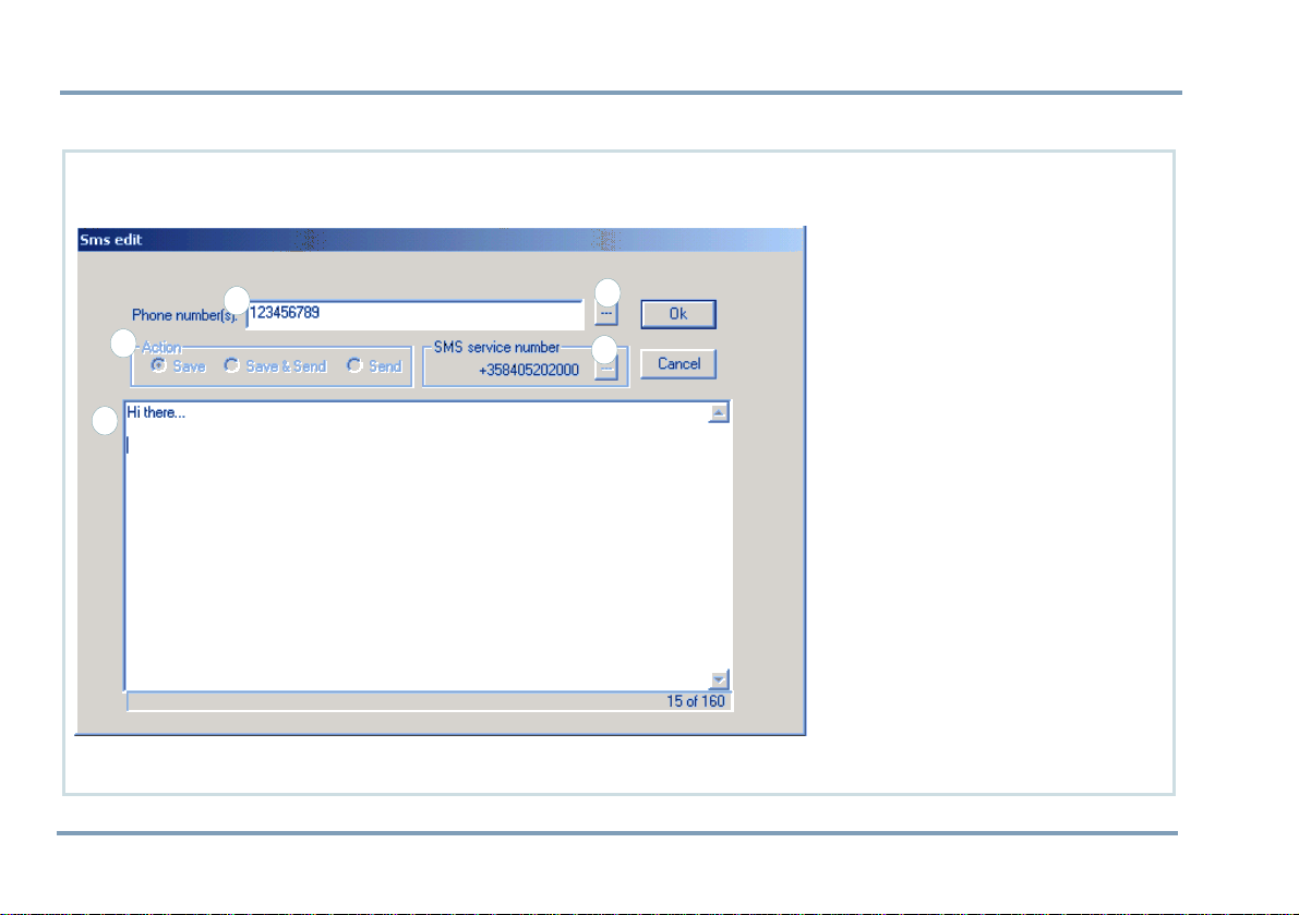
1. Choose Sms, New message from
the
Edit menu. The SMS edit
buffer will be displayed.
2. Key in the message text (1) and
3
4
the recipient´s number(2). By
clicking the square next to the
number (3), the recipient´s
number can be fetched from the
Phone book, assuming the num-
ber is found on SIM.
3. Make sure, the
is correct. The number can
ber
be changed by clicking the
square next to it (4). By selecting the option
the SMS service number will be
picked up from the SIM card. If
the SIM card does not contain
the SMS number, select the option
Own and key in the SMS ser-
vice number.
4. Select the desired Saving/Send-
ing option by checking one of
the
Action boxes (5).
5. Complete the message by press-
ing
Ok.
Sms service num-
SIM card default,
12 SHORT MESSAGES
Page 13
PART A: CONFIGURING SETTINGS FOR THE TRACKBOX
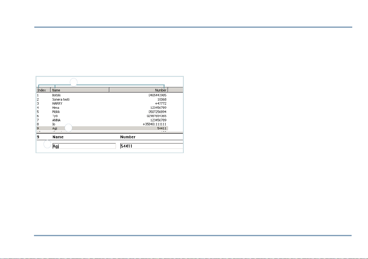
PHONE BOOKS
As you open the Phone books, the memory entries stored on
the SIM card are listed and can be processed.
stands for memory slot number.
3
1
2
Index number
Editing and adding an entry
1. To edit details of an entry, highlight the desired entry
(1). To add a new phone book entry, click a blank line.
2. Key in the name and number in the lower part of the
Document window (2).
3. By pressing
data field to another.
4. Press
Tab on the keyboard you can move from a
Enter on the keyboard to confirm changes.
Deleting entries
1. To delete a phone book entry, click the desired entry.
2. Press
Delete on the keyboard. You can also choose the
command
mouse´s right button.
Delete from the Edit menu, or by clicking the
Arranging entries
Arrange the phone book by Index, Name, or Number (3) either by
- clicking the title
- choosing the option from the Edit menu
- clicking the mouse´s right button.
•View by: This option rearranges the phone book tempo-
rarily. When transferring the phone book data back to the
phone, the data will be arranged by the old order.
•
Sort by: This option rearranges the phone book perma-
nently. When transferring the phone book data back to
the phone, the data will be arranged by the new order.
PHONE BOOKS 13
Page 14
PART A: CONFIGURING SETTINGS FOR THE TRACKBOX
Moving and copying entries
1. To move or copy a phone book entry to another slot,
click the desired entry.
2. Press Ctrl+C (for copy) or Ctrl+X (for cut) on the keyboard. Click the destination line and press Ctrl+V (for
paste) on the keyboard.
You can also choose the commands
from the Edit menu, or by clicking the mouse´s right button.
Or, you can click the corresponding function icons on
the toolbar.
Copy
3. If the destination line is reserved, you also need to confirm, whether to overwrite the old information or not.
- To overwrite the old information, click Yes in the dia-
log box.
- To preserve the old information and transfer the new
information to another, free slot (Index number), click
No in the dialog box.
Cut
Copy, Cut and Paste
Paste
USER SETTINGS
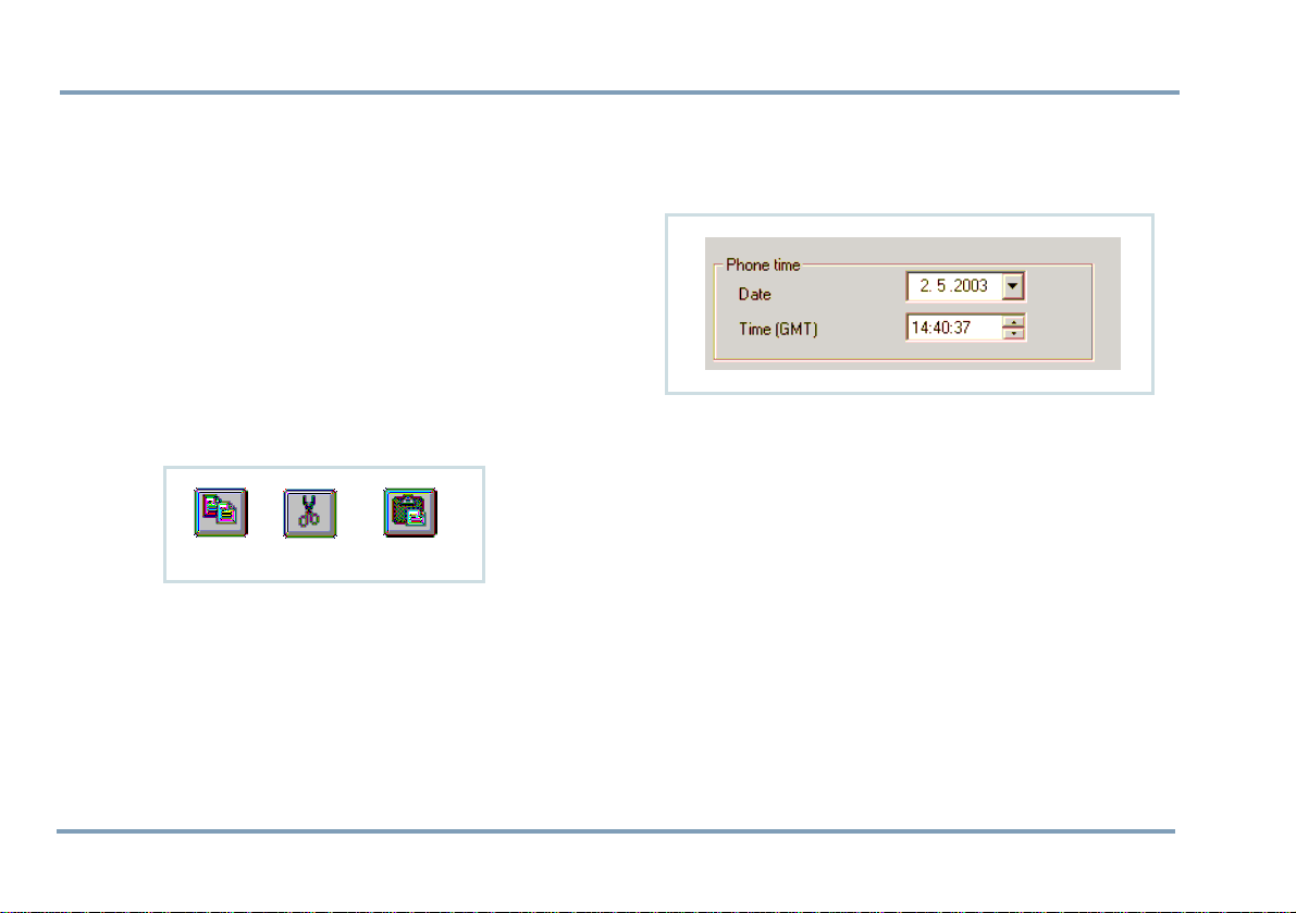
Phone time and date
Time and date can be set in the Benewin software. Key in the
time and date in the GMT format (“Greenwich Time”). Date
and time can be selected by clicking the arrows, as well.
Time stamps associating MPTP messages are displayed in the
GMT format, as well.
Activity timer
Device can be configured to update its position e.g. once a
day and report it to the service center.
Activity timer can also be used to wake up the device periodically to check if there are any incoming messages. If there
are no messages, the timer will return to sleep for the next
wake-up.
Power up/down cycle is reasonable for saving power, especially in case the device is a plain battery model.
14 USER SETTINGS
Page 15
PART A: CONFIGURING SETTINGS FOR THE TRACKBOX
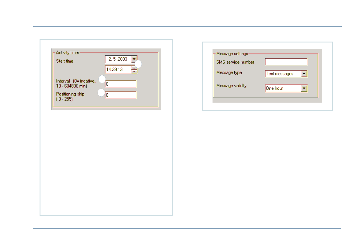
SETTING THE ACTIVITY TIMER
1
2
3
1.
Start time: Key in the date and time, when the
timer is switched on for the first time. Start
time can be selected by clicking the arrows
(1), as well.
2.
Interval: Key in the interval for wake-up (2). If
the interval is set to zero, the timer is NOT in
use.
3.
Positioning skip: It may not be necessary to de-
termine current position each time when the
timer is turned on. By setting a value N for the
position skip (3), the device can be programmed to only determine the position every
Nth time the timer is turned on.
Message settings
SMS SERVICE NUMBER
You can store the SMS service number, which is needed for
sending normal short messages and telematics protocol
messages.
The number must be set correctly, otherwise sending short
messages is not possible.
The SMS service number can be found e.g. in the manual of
your local network operator.
However, if you are supplied with a separate SMS service
number for telematics protocol messages, you may store the
number in the
mation, see
Protocol settings data field. For more infor-
GENERAL TELEMATIC SETTINGS ON PAGE 24.
USER SETTINGS 15
Page 16

PART A: CONFIGURING SETTINGS FOR THE TRACKBOX
Configuring separate SMS service number for protocol messages is recommended in case the
Activity timer is used.
MESSAGE TYPE
You can determine what kind of a message you are processing. You can choose the message type from these:
X400, Email, Ermes, or Data.
Click the arrow and highlight the desired option.
Text, Fax,
MESSAGE VALIDITY TIME
You can select the length of validity for normal SMS messages, i.e. for how long the SMS messages are stored in the serv-
er of the operator.
You can choose the message validity from these:
hours
, 24 hours, 1 week or Maximum time.
Click the arrow and highlight the desired option.
NOTE: The length of validity for telematics protocol messag-
es is selected in
tion, see
General telematic settings. For more informa-
GENERAL TELEMATIC SETTINGS ON PAGE 24.
1 hour, 6
Port and audio settings
AUTOMATIC ANSWER
The automatic answer function can be turned on or off.
•If the
Automatic answer is turned on (the box is checked),
a voice call to the device from any number is possible.
•If the
Automatic answer is turned off (the check box is left
blank), making a voice call to the device can only be done
from a number listed as an allowed caller. Allowed
callers are stored in the
more information, see
.
PAGE 24
General telematics settings. For
GENERAL TELEMATIC SETTINGS ON
16 USER SETTINGS
Page 17

PART A: CONFIGURING SETTINGS FOR THE TRACKBOX
The device contains a built-in microphone. By making a call
to the Trackbox, the caller (e.g. service center) can listen in
the Trackbox and its surroundings. After certain number of
rings, the device answers an incoming call automatically by
opening audio connection.
DATA PORT ACTIVITY
Data port setting must be turned on in case the Trackbox is
needed for data transfer or connected to some external device.
Turning the data port off decreases power consumption.
•To turn the data port on, check the box.
•To turn the data port off, leave the check box blank.
AUDIO
•Internal: The device contains an internal microphone and
uses it.
•
External: Audio comes from some external device via the
configuration port.
Click the arrow and highlight the currently used option.
VISIBLE MODE
The device can be set to operate
•In visible mode (the box is checked) or
•In invisible mode (the box is left blank).
In
Visible mode the LEDs are lit as described in the Track-
box Installation Guide.
Invisible mode is for making the device more difficult to de-
tect. In invisible mode only some of basic LED patterns are
lit, e.g. powering up/down. This way e.g. sending emergency messages can be done very discreetly.
USER SETTINGS 17
Page 18
PART A: CONFIGURING SETTINGS FOR THE TRACKBOX
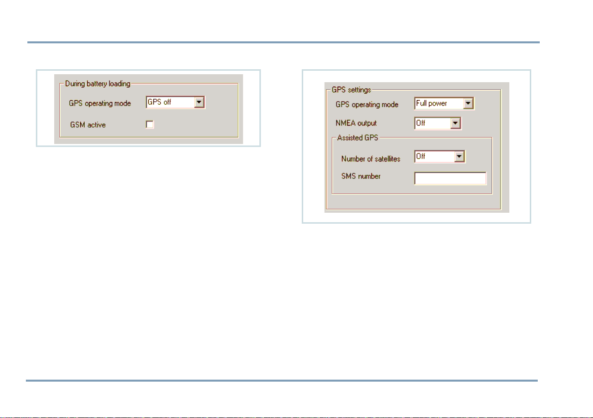
Settings during battery loading
GPS OPERATING MODE
You can select, which one of the GPS power modes is on
while the device is being charged.
Set the
GPS off, in case
•the time reserved for charging is quite short or
•GPS functions are not needed during charging process.
By selecting
ously configured mode.
You can select, whether the GSM is turned on or off while
the device is being charged.
In case the GSM functions are needed even during the
charging, this setting must be turned on.
By checking the box, the GSM is activated during charging.
No change, the GPS mode remains in the previ-
GSM ACTIVATION
GPS settings
GPS OPERATING MODE
The GPS receiver in the Trackbox uses power saving options
for ensuring maximum battery capacity.
The GPS receiver has three modes:
•
Off
•Low Power with the power saving option
- the time needed for position fix depends on conditions. If the GPS does not manage to calculate the position, it will fall asleep for a while and retry to calculate
the position later on
18 USER SETTINGS
Page 19

PART A: CONFIGURING SETTINGS FOR THE TRACKBOX
•Full power without the power saving option.
Operating mode depends on the way, the device is used.
Autonomous system, i.e. a plain battery model, normally
uses either
stant power supply uses
(i.e. the standard and I/O models).
Low Power or Off mode, while a device with con-
Full Power mode
GPS ECONOMY POWER INTERVAL
Key in the interval for sleeping time in the GPS Economy
mode. In addition to sleeping time, the device needs some
time for searching satellites and calculating position (the
time needed for this depends on present circumstances).
NOTE: This setting is only available in some special models.
NMEA OUTPUT
The NMEA port output can be turned on or off. This device
supports the NMEA 0183 v2.0 output protocol, which is
used for transferring position data between the device and
a navigation system, such as a Search and Rescue application. For the connection you also need a BWTrackbox Data/
NMEA cable (an accessory).
- By selecting Off, you will turn the NMEA output port
off.
- By selecting a transferring speed you will turn the
NMEA output port on.
When the NMEA output is turned on, the device will consume slightly more power.
ASSISTED GPS
Trackbox has capability to receive assistance to the GPS receiver in order to speed up the initial position calculation.
This is very useful feature if the device is in poor satellite
coverage.
Assistance can be supplied over the Mobile Phone Telematics Protocol in a binary coded protocol message. The message will contain ephemeric and almanac data which is
based on a rough position calculated by e.g. GSM network
parameters (Cell-ID, CI-TA etc). The assisted GPS is supplied from a third party station server.
Using the AGPS does NOT affect the accuracy of the position. If the last position fix is deemed to be too old, and the
AGPS is set, the AGPS feature is automatically used to speed
up the position determination.
The cost of the AGPS service is determined on the contract
of the service provider.
You can specify settings for ordering assisted GPS information from a service provider.
•
Number of satellites: Select the number of satellites.
However, please note that the more satellites selected, the
faster the service but the higher the charge.
•
SMS number: Key in the SMS number of the AGPS service.
USER SETTINGS 19
Page 20

PART A: CONFIGURING SETTINGS FOR THE TRACKBOX
TELEMATIC SETTINGS
Tracking settings
TRACKING
Tracking is remotely controlled by the service center. When
the tracking function is turned on, the position information
is sent to the service center several times in sequence.
If the device is temporarily switched off, battery is removed,
or the power supply is some other way disconnected, the
tracking record (e.g. amount of messages) will be reset and
start from the beginning.
Essential phone numbers, such as
SMS service number, must be configured in the device. In the
Benewin software, these numbers can be set in the
telematic settings
TELEMATIC SETTINGS ON PAGE 24
. For more information, see GENERAL
Service center number and
General
.
Interval
The given interval, e.g. 60 minutes, indicates that the device
will send its position to the service center at intervals of 60
minutes. Key in the tracking interval in minutes.
20 TELEMATIC SETTINGS
Page 21

PART A: CONFIGURING SETTINGS FOR THE TRACKBOX
Duration
You can select, for how long or on what terms tracking will
be on. After that, the tracking will be turned off automatically. Only one of these options can be turned on at once.
•
Continuous: The tracking will be turned on until further
notice. !Deactivation message must be sent separately.
•
Amount of sent messages: Tracking will be on until
defined amount of messages has been sent to the service
center. Key in the amount.
•
Duration: Tracking will be on for a period of time. Key in
how many days, hours and minutes, the tracking should
be on.
•
End time: Tracking will be on until the end time is
reached. Key in the date and time, the tracking should be
turned off. Date and time can be selected by clicking the
arrows, as well.
Activation
Make sure all the required settings for tracking are completed before activating the function. Such settings are, e.g. duration and interval.
New settings can be applied only while the tracking is deactivated.
There are two ways to turn the tracking on or off:
•
Remote activation/deactivation: Send a specific MPTP mes-
sage to the device.
•
Local activation/deactivation: Set tracking on or off by
using the Benewin software (or some similar application)
and transfer the setting to the device via the data cable.
In the Benewin set the tracking as follows:
1. Make sure, the device is connected to the Benewin.
2. Click the
3. Select
ly click the
button.
4. The tracking will be turned on only after the service center sends a confirmation message.
Mobile menu.
Activate/Deactivate in the pop-up menu, and final-
Send tracking activation/deactivation request
TELEMATIC SETTINGS 21
Page 22

PART A: CONFIGURING SETTINGS FOR THE TRACKBOX
REAL TIME TRACKING
The Real time tracking can be initiated by sending a detailed
MPTP message to the device.
Real time tracking is done via CSD data call. After successful
connection the device starts to forward NMEA data directly
from the GPS over CSD call.
If sending a CSD call fails, the device will send an SMS message informing what went wrong.
•Key in the
in the device before the function can be used.
•Key in the
in the device, as well.
CSD number. The number must be configured
SMS number. The number must be configured
AREA TRACKING
Area tracking is remotely controlled by the service center (or
some other authorized number). When the area tracking is
turned on, the position information will be sent to the service center only when the device is moving in or out of the
pre-defined area.
The area can be determined by keying in a center point and
a radius of an area. The area tracking does not contain the
duration option, i.e. the area tracking will never be turned
off automatically.
Essential phone numbers, such as
SMS service number must be configured in the device. In the
Benewin Trackbox software, these numbers can be set in the
General telematic settings. For more information, see GENER-
AL TELEMATIC SETTINGS ON PAGE 24
Service center number and
.
Interval
The given interval, e.g. 60 minutes, indicates that the device
will send its position to the service center at intervals of 60
minutes, but only in case the device is located outside of the
determined area.
Key in the interval for area tracking in minutes.
22 TELEMATIC SETTINGS
Page 23

PART A: CONFIGURING SETTINGS FOR THE TRACKBOX
Center point
Key in the center point name (e.g. Home) and enter coordinates.
Radius
Key in the desired radius in 10 meters. E.g. by entering 5,
your actual radius will be set for 50 meters (minimum).
Alarm mode
You can set an alarm to alert when crossing the borderline
of an area.
The alarm can be set to alert either when arriving in or departing from the particular area.
Activation
Make sure all the required settings for area tracking are
completed before activating the function. Such settings are,
e.g. interval, center point, radius and alarm mode (at arrival
or departure).
New settings can be applied only while the area tracking is
deactivated.
There are two ways to activate the area tracking:
•
Remote activation/deactivation: Send a specific MPTP mes-
sage to the device.
•
Local activation/deactivation: Set the area tracking on or
off by using the Benewin software or some similar application and transfer the setting to the device via the data
cable.
In the Benewin set the area tracking as follows:
1. Make sure, the device is connected to the Benewin.
2. Click the
3. Select
ly click the
quest
4. The area tracking will be turned on only after the service
center sends a confirmation message.
Mobile menu.
Activate/Deactivate in the pop-up menu, and final-
Send area tracking activation/deactivation re-
button.
TELEMATIC SETTINGS 23
Page 24

PART A: CONFIGURING SETTINGS FOR THE TRACKBOX
General telematic settings
24 TELEMATIC SETTINGS
Page 25

PART A: CONFIGURING SETTINGS FOR THE TRACKBOX
SERVICE CENTER NUMBER
You can change and store the phone number, which is used
for sending telematics protocol messages to the service center.
Key in the number for the service center.
LIST OF ALLOWED CALLERS
You can set several numbers for allowed callers. You can
also attach the automatic answer function to the desired
numbers.
Allowed callers are the ones, who are permitted to call to
the device at any time: Calls from these specific numbers are
always put through.
Key in the name and the number of an allowed caller. If you
want the device to answer automatically to calls coming
from certain numbers, make sure to check those boxes, as
well.
PROTOCOL SETTINGS
Authorization
You can select whether to receive protocol messages from
anyone or only from authorized numbers.
•If the authorization setting is
numbers are valid senders of a protocol message and
reply to the protocol message will be sent back to the
same number.
•If the setting is
can be anyone, e.g. the message can be sent from the
Internet or the number can be blank. If the service center
number is set, reply is always sent to the service center. If
the service center number is NOT set, reply is sent to the
sender of a protocol message (assuming the sender´s
number is available).
Disabled, the sender of a protocol message
Enabled, only authorized
MPTP protocol message storage
If sending of an MPTP message fails, the device will send the
message later, assuming the MPTP protocol message storage
is turned on and there is space left to deposit the message.
•To turn the message storage on, check the box.
•To turn the message storage off, leave the check box
blank.
TELEMATIC SETTINGS 25
Page 26

PART A: CONFIGURING SETTINGS FOR THE TRACKBOX
By checking the box, you select that the telematics protocol
messages are put into storage, if e.g. there is no service at
the moment. The storage capacity is 100 messages. After the
device is in service again, these messages are automatically
sent forward.
Message validity
You can select the length of validity for telematics protocol
messages, i.e. for how long the SMS messages are stored in
the server of the operator.
This setting can be used to avoid massive helping efforts in
case an emergency message has been sent a week ago and
there is reason to believe that help is no longer needed.
You can choose the message validity from these:
, 24 hours, 1 week or Maximum time.
hours
The length of validity for normal SMS messages is selected
elsewhere, in the
MESSAGE VALIDITY TIME ON PAGE 16.
User settings. For more information, see
SMS service number
You can set separate SMS service number for the telematics
protocol messages. If the number is not set, the normal
short message service number is used instead.
1 hour, 6
26 TELEMATIC SETTINGS
Page 27

PART A: CONFIGURING SETTINGS FOR THE TRACKBOX
Emergency settings
TELEMATIC SETTINGS 27
Page 28

PART A: CONFIGURING SETTINGS FOR THE TRACKBOX
EMERGENCY CONFIRMATION
You can request the emergency center to send a confirmation of the emergency message. The emergency center will
then send the confirmation to the device as soon as it receives the emergency message. Check the box to enable confirmation, or leave the check box blank to disable
confirmation.
You can also specify a waiting time, i.e. for how long a time
the device waits for the confirmation before trying to reach
some other emergency center number. Click the arrow and
highlight the desired option.
EMERGENCY CALL CYCLE MODE
You can define the order for making emergency voice calls
and sending emergency messages while the emergency call
cycle is on.
You have two choices:
•
Alternately: The device will make a voice call and send an
SMS in pairs according to the list order, starting from the
top.
•
First SMS, then calls: As the emergency call cycle is initi-
ated, first the device will send the emergency messages,
after which the voice calls will be made starting from the
top of the list.
EMERGENCY CALL CONNECTION WAITING
TIME
You can define for how long a time the device tries to call a
single emergency center number before moving on to the
next number in the list of emergency center numbers.
Click the arrow and highlight the desired option.
EMERGENCY CENTER NUMBERS
The emergency (SOS) messages are sent and emergency
calls are made to the numbers stored in the emergency center list.
The numbers are in priority order, starting from the top of
the list. These numbers work as "a chain":
If the first number is unreachable (after two attempts), the
device calls or sends the short message to the second number. If it is not answered either, the device will go on to the
third number on the list and so on.
The device tries to reach contact with the other numbers
once before moving on to the next number in the list. If
there is still no answer after going through the whole list,
the calling procedure will be started all over.
You can have two numbers (a phone number and an SMS)
associated with each emergency center number.
To enable a number, check the box which associates the
number.
28 TELEMATIC SETTINGS
Page 29

PART A: CONFIGURING SETTINGS FOR THE TRACKBOX
DIGITAL INPUT PIN
FOR EMERGENCY CALLS
There are several configurable settings for the emergency
input pin:
Turning the emergency pin on or off
•Enabled: The emergency input pin is in use when the box
is checked.
•The input pin is NOT in use when the check box is left
blank. A signal of this pin is NOT detected at all.
Setting normal status
•Status: The circuit can be set to be closed High, or opened
Low. Click the arrow and highlight the desired option.
•A change in the state of a circuit causes grounding of a
pin. An event causing this could be, e.g. pressing the
emergency switch.
•After the change is registered, the device will start an
emergency cycle and also store the information in the
Event log, if the Event log is enabled.
- For more information on Emergency cycle, see EMER-
GENCY CYCLE (I/O MODEL ONLY) ON PAGE 42
- For more information on Event log, see
PAGE 35
.
.
EVENT LOG ON
Defining response time
Notification delay: The device can be configured to allow
some millseconds to pass until the event will be registered
or interpreted as a cause for making an alarm.
Key in the time for allowed delay in millseconds.
TELEMATIC SETTINGS 29
Page 30

PART A: CONFIGURING SETTINGS FOR THE TRACKBOX
Authorized numbers
The device is allowed to send protocol messages to the
authorized numbers automatically.
Authorized numbers are:
•the numbers stored in the
•the
Emergency center numbers and
•the
Service center number.
For more, see
EMERGENCY CENTER NUMBERS ON PAGE 28.
NOTE: If the requesting number is unauthorized,
sending response depends on
center number
•
Authorization setting Enabled, -> The device ignores the
request, i.e. does nothing.
•
Authorization setting Disabled, Service center number
NOT set ->Response goes to the requesting number.
•
Authorization setting Disabled, Service center number is
set ->Response always goes to service center.
For more on Authorization setting, see AUTHORIZATION ON
PAGE 25
.
SERVICE CENTER NUMBER ON PAGE 25 and
settings.
Authorized numbers list and
Authorization and Service
30 TELEMATIC SETTINGS
Page 31

1 23
4
5
PART A: CONFIGURING SETTINGS FOR THE TRACKBOX
Status messages
A status message is a special short message, which includes
the status message text, additional text information and
the position information (i.e. coordinates or some other
MPTP information). If the current position information is
not available, the previous coordinates will be sent instead.
Message text can contain information on opened/closed
door, temperature/liquid level changes etc.
Creating status messages
In the Benewin software you can create and define status
messages. Key in the desired status message text (1) and
the phone number (2) to which the status message will be
sent. In case receiving party of a status message needs to
be authorized for some reason, make sure to copy the corresponding destination number to the list of authorized
numbers.
Additional information (3) can - according to your choice include details of some sort but the data field can be left
blank, as well.
Status messages are related to certain pins. The status messages 1 - 9 on the upper data field (4) stand for digital input pins 1 - 9.
The status messages 1 - 4 on the lower data field (5) stand
for analogue input pins 1 - 4.
TELEMATIC SETTINGS 31
Page 32

PART A: CONFIGURING SETTINGS FOR THE TRACKBOX
Pin settings
DIGITAL OUTPUTS
1
Turning the output pin on or off
•Enabled: The output pin is in use when the box is checked
(1).
•The output pin is NOT in use when the check box is left
blank. A signal of this pin is NOT detected at all.
Setting normal status
•Status: The circuit can be set to be closed High (2), or
opened
Low. Click the arrow and highlight the desired
option.
•A change in the state of a circuit causes grounding of a
3
2
pin. The change can be done by sending a specific MPTP
message to the device. The desired action could be, e.g.
swiching an electric sauna on remotely.
•After the change is registered, the device will proceed the
way it is configured: It will store the information in the
Event log (if the Event log is Enabled) and/or send a notifi-
cation of the event to the requesting number as a reply (if
the
Notification enabled is checked).
Sending notification
•Notification enabled: By checking the box (3), the device
will send a notification (as a digital output pin control
msg) if the normal status of this pin changes.
•By leaving the check box blank, the device will NOT send
notifications at all.
32 TELEMATIC SETTINGS
Page 33

PART A: CONFIGURING SETTINGS FOR THE TRACKBOX
DIGITAL INPUTS
2
1
Turning the input pin on or off
•Enabled: The input pin is in use when the box is checked.
•The input pin is NOT in use when the check box is left
blank (1). A signal of this pin will NOT be detected at all.
Setting normal status
•Status: The circuit can be set to be closed High, or opened
Low. Click the arrow and highlight the desired option.
•A change in the state of a circuit causes grounding of a
pin. An event causing this could be, e.g. opening a door.
•After the change is registered, the device will proceed the
way it is configured: It will store the information in the
Event log (if the Event log is Enabled) and/or send a notifi-
cation of the event to the pre-configured number as a status message (if the
Notification enabled is checked).
Sending notification
•Notification enabled: By checking the box, the device will
send a notification (as a status message) if the normal status of this pin changes.
•By leaving the check box blank, the device will NOT send
notifications at all.
Defining response time
•Notification delay: The device can be configured to allow
some millseconds to pass until the event will be registered or interpreted as a cause for taking an action. E.g.
an action would take place only in case a door is wide
open for at least X millseconds.
•Key in the time for allowed delay (2) in millseconds.
TELEMATIC SETTINGS 33
Page 34

PART A: CONFIGURING SETTINGS FOR THE TRACKBOX
ANALOGUE INPUTS
Turning the input pin on or off
•Enabled: The input pin is in use when the box is checked.
•The input pin is NOT in use when the check box is left
blank. A signal of this pin is NOT detected at all.
Setting normal status
•Status: The circuit can be configured to have level values
for
High and Low. Click the arrow and highlight the
desired option.
•Exceeding a limit value causes grounding of a pin. An
event causing this could be, e.g. a sudden increase/
decrease in liquid level or a crucial change in temperature.
•After the change is registered, the device will proceed the
way it is configured: It will store the information in the
Event log (if the Event log is Enabled) and/or send a notifi-
cation of the event to the pre-configured number as a status message (if
Notification enabled is checked).
Sending notification
•Notification enabled: By checking the box, the device will
send a notification (as a status message) if the normal status of this pin changes.
•By leaving the check box blank, the device will NOT send
notifications at all.
Defining response time
•Notification delay: The device can be configured to allow
some millseconds to pass until the event will be registered or interpreted as a cause for executing an action.
•Key in the time for allowed delay in millseconds.
Setting reference values
Threshold values per full scale (0-10V) must be set separately for high and low.
34 TELEMATIC SETTINGS
Page 35

PART A: CONFIGURING SETTINGS FOR THE TRACKBOX
Log settings
EVENT LOG
1
2
3
4
5
The device can be configured to collect incoming/outgoing
data from the I/O pins. The device can also be configured to
store plain positions at defined intervals.
Stored data may contain information on battery level, position, date and time, speed, direction, triggered event, event
value, ID, type and so on.
Turning the Event log on or off
•Enabled: The device will gather pin information, i.e.
events registered by a pin, in the
•
Disabled: The device does NOT gather any pin informa-
tion in the
Event log (1).
Event log.
Event log transmission limit
The limit (2) indicates how much space is left for events in
the
Event log. The smaller the number you set in here, the
more stuffed the log will be before the device sends the log
or even informs of it.
NOTE: Event log limit value depends on Flash memory capacity of the device model, e.g. Normal 3840 or Extended
7936 pieces at maximum.
The limit also works as a trigger: When the limit is reached,
the device will take action, e.g. send the log information as
a CSD data call to the pre-configured CSD number. Action
depends on configuration made in the
event log is full.
LOG FULL PROCEDURE ON PAGE 36
For more information on it, see below EVENT
.
What to do, when
TELEMATIC SETTINGS 35
Page 36

PART A: CONFIGURING SETTINGS FOR THE TRACKBOX
Event log full procedure
With this "event log full" setting (3) you can define how to
proceed when the log is about to reach limit. You can
choose from these options:
•
No notification: No action at all. The log will do nothing
else but preserve the already collected log information (if
the
Event log is Enabled). When the log is full, there is no
space for new log information. The service center will
NOT be informed of this at all.
However, it is still possible to recall (or clear) the log
"over the air" by sending a specific MPTP message separately to the device.
•
CSD: When the log reaches the limit, the log information
will be sent automatically as a CSD call to a pre-configured CSD number. There are three sending attempts.
•
SMS: When the log reaches the limit, the device will send
an SMS notification informing that the log is almost full. A
new log information cannot be stored unless the old log
has been separately cleared or recalled by the service center or an authorized number.
•
First SMS, then CSD: When the log reaches the limit, an
SMS notification will be sent informing the service center
of an incoming log transfer. Then the log information will
be sent automatically as a CSD call to a pre-configured
CSD number. There are three sending attempts.
CSD number
Key in the CSD data call number (4). The number is needed
for transferring log information from the device to the receiving mobile phone, which is connected to the computer.
NOTE: In order to use the CSD data connection, you need
to have a specific SIM card, which is equipped with high
speed multidata feature. Multidata feature includes a separate data call phone number (i.e. CSD number) for data reception. In order to get this feature, please contact your
network operator.
Insert this specific SIM card in the receiving mobile phone,
(to which the log will be sent).
For more information on receiving the log, see
TRANSFER ON PAGE 50
.
REMOTE
SMS number
Key in the SMS number (5).
The number is needed in order to inform and warn the service center of some events and errors which may occur on
the way.
36 TELEMATIC SETTINGS
Page 37

PART A: CONFIGURING SETTINGS FOR THE TRACKBOX
T
RANSFERRING OR CLEARING THE LOG
In order to be able to collect new log i nf ormati on , th e ol d lo g information must be transferred or cleared.
1. If the selected procedure option contains a CSD call, the
old log will be cleared automatically after successful CSD
call.
- However, the CSD data call can fail for reasons, such as:
CSD number is not set, establishing data call connection is
failed, ongoing data call is disconnected, or an emergency
call (or some other primary function) is activated during
the data call transmission.
- If the CSD call fails after three attempts, an SMS will be
sent to the service center informing of reasons for failure.
2. Clearing or transferring the log can also be done individually, by sending a specific MPTP message to the device,
after which the device sends or deletes the log.
- Proceed this way if the CSD call fails after three attempts,
or the selected procedure option does not contain a CSD
call at all.
3. The Event log information can also be transferred or
cleared locally, by using the Benewin software and
BWTrackbox cable.
- You may proceed this way if you can wait until the device "returns home".
For more information on entire process, see also RECALLING
LOGGED DATA (I/O MODEL ONLY) ON PAGE 49
.
POSITION LOG INTERVAL
With the position log interval setting you can determine the
device to store plain positions at pre-defined intervals. This
way positions are calculated and logged more frequently.
Key in the interval in seconds. The interval can be 65535 seconds, at maximum.
If the value is set to zero (0), the position log interval is NOT
in use.
TELEMATIC SETTINGS 37
Page 38

PART A: CONFIGURING SETTINGS FOR THE TRACKBOX
Waypoint tracking
1 2 3 4 5
Waypoint tracking is remotely controlled by the service center. When the waypoint tracking is turned on, the position
information will be sent to the service center only when the
device is moving in to the pre-defined area.
NOTE: If the device moves in to the same area more than
once, new tracking messages will be sent only in case the device has been far away (over 100 meters of the borderline)
and stayed far away for over a minute before returning back
in.
You can determine up to 30 separate, circular areas. The areas are separated from each other by defining an ID number
(1) and a name (3) individually for each area.
The waypoint area can be determined by keying in center
point coordinates, both latitude and longitude (4) and a radius of an area in 10 meters (5). E.g. by entering 5, your actual radius will be set for 50 meters (minimum).
To activate the waypoint, check the
tivate the waypoint, leave the check box blank.
NOTE: The waypoint tracking does not contain interval or
duration options, i.e. the waypoint tracking must be separately deactivated when it is no longer needed.
Essential phone numbers, such as
SMS service number must be configured in the device. In the
Benewin Trackbox software, these numbers can be set in the
General telematic settings. For more information, see GENER-
AL TELEMATIC SETTINGS ON PAGE 24
Active box (2), to deac-
Service center number and
.
38 TELEMATIC SETTINGS
Page 39

PART A: CONFIGURING SETTINGS FOR THE TRACKBOX
CODE SETTINGS
Automatic PIN entry
The PIN code can be pre-programmed to the device
EEPROM. It cannot be read by any means from the device.
In startup the PIN code is entered automatically by the device software.
The PIN code can be changed in the Benewin by choosing
Change PIN code from the Mobile menu. Key in the new code
and confirm it.
The option is available only when the Trackbox is connected
to the software.
Security code
The security code secures telematic settings. If the setting is
enabled, the code is requested each time when powering up
the system (software in connection with the device).
The security code settings are located in the
- To enable the code, check the box. To disable the
code, leave the check box blank.
- To change the code, first click the corresponding box.
Key in the old code, key in the new code and confirm it.
Mobile menu.
CODE SETTINGS 39
Page 40

PART B: OPERATING THE TRACKBOX
PART B: OPERATING THE
TRACKBOX
INCOMING CALLS AND MESSAGES
The device can receive calls, messages and requests. With
such messages you will make the device to activate functions, update settings, send positions or logged data and so
on.
For incoming calls and messages
•a valid SIM card must be inserted and
•the device must be turned on.
Incoming calls
It is possible to listen in the Trackbox and its surroundings.
The device answers an incoming call automatically after certain number of rings,
The
Auto answer setting must be turned on (the box must be
checked), otherwise an incoming call is dropped at once.
The
Audio setting should be set to Internal, when using the
device´s own built-in microphone.
Incoming short messages
An incoming short message is echoed to the system connector, so that an external device can check it. Reading, writing,
sending and receiving normal short messages via the Trackbox is possible only in case the Trackbox is connected to an
external device, such as a computer. For more information,
see
SHORT MESSAGES ON PAGE 11.
No messages are ever stored on SIM card. Even the MPTP
messages are cleared once they are processed.
Incoming MPTP messages
An incoming short message is processed only if it is a known
MPTP message.
If the
Authorization setting is enabled, only messages from
authorized numbers are processed, others are discarded at
once. For more information, see
Authorized numbers include service center and emergency
center numbers and all the numbers stored in the list of authorized numbers. For more information, see
NUMBERS ON PAGE 30
.
AUTHORIZATION ON PAGE 25.
AUTHORIZED
40 INCOMING CALLS AND MESSAGES
Page 41

PART B: OPERATING THE TRACKBOX
REMOTE CONFIGURATION MESSAGE
The device may receive a specific MPTP message for the remote configuration. Remote configuration messages contain new or updated settings for e.g. emergency numbers,
authorized numbers, AGPS-parameters, activity timer and
GPS operating mode.
For more information on remote configuration, see the separate MPTP document.
SYSTEM CONNECTOR CONTROL MESSAGE
The device may receive a specified MPTP message for the
system connector setting. According to the parameters of
the message, the setting will turn a pin connector on or off.
The pin connectors are located inside the device, in the accessory module.
LOCATION REQUEST MESSAGES
The device may receive several different messages requesting location. Such messages could be, e.g. Location request
(LOC) messages, Location history request, Latest position
(?HIS) messages. For more information on how the device
responds these messages, see
47
.
For more information on how to create location request
messages, see the separate MPTP document.
POSITIONING FEATURES ON PAGE
AT commands
The device may receive an AT command via the configuration port.
The port is located inside the device, in the lower left part
of the accessory module. For more information, see
CONFIGURATION PORT ON PAGE 8
The AT commands can be used for carrying out similar
things that are done via MPTP messages.
For example, AT commands are used when configuring settings with the Benewin software.
For more information on handling AT commands, please see
the separate document on AT commands, located at the Web
site www.benefon.com.
.
THE
INCOMING CALLS AND MESSAGES 41
Page 42

PART B: OPERATING THE TRACKBOX
OUTGOING CALLS AND MESSAGES
Depending on the configuration, the device may send some
MPTP messages to the service center or authorized numbers.
Such messages can be, e.g. power notifications or calculated
positions.
Power notifications
BATTERY LOW MESSAGE
When the device detects the battery is low, the device will
send an appropriate MPTP message to a specific number, assuming the MPTP power notifications are enabled.
The message will be sent only in case the event takes place
for the first time after powering up or being disconnected
from the mains.
MAINS CONNECTION/DISCONNECTION
MESSAGE
When the device detects that it is being connected to or disconnected from mains, the device will send an appropriate
MPTP message to a specific number, assuming the MPTP
power notifications are enabled.
Emergency cycle (I/O model only)
EMERGENCY MESSAGES AND CALLS
In order to send emergency messages, the device must have
I/O functionality and a separate emergency switch. The
emergency switch can also be some kind of light/movement/
pressure indicator. Additionally the device must be configured correctly. For more information on emergency settings, see
As the emergency cycle takes place, the device is turned on
automatically (if it is currently off).
The emergency message contains both GPS coordinates and
GSM network measurement report.
The emergency message (including the latest position information available) is put through via the emergency input pin
and I/O cable.
If an external audio (a combination of a microphone and
speaker) is connected, a voice call to both ways is possible.
Otherwise voice call means opening one-way audio: from
the device to the emergency center number.
EMERGENCY SETTINGS ON PAGE 27.
42 OUTGOING CALLS AND MESSAGES
Page 43

PART B: OPERATING THE TRACKBOX
EMERGENCY CYCLE CHECK LIST
Necessary settings
1. The device must be the I/O model, which includes the
I/O functionality.
2. SIM card must be inserted in the device.
3. All required settings must be configured and trans-
ferred in the device in advance. Such settings are listed
below.
- Configuring settings can be done either by using the
BeneWin software and transferring the settings to the
device locally, via the data cable, OR by using the MPTP
messages and transferring the settings remotely as an
OTA (Over the Air) message.
4. Emergency center numbers must be set in the device.
For more information, see
ON PAGE 28
.
EMERGENCY CENTER NUMBERS
5. The emergency pin must be enabled. For more infor-
mation, see
PAGE 29
TURNING THE EMERGENCY PIN ON OR OFF ON
.
6. Normal status for the emergency pin must be de-
fined. A change in the normal status works as a trigger
for an emergency cycle to start. For more information,
see
SETTING NORMAL STATUS ON PAGE 29.
Voluntary settings
1. Emergency message confirmation can be set. For
more information, see
.
PAGE 28
- If the emergency confirmation is activated, the device
waits for an acknowledgement message. If it is not getting it in the pre-defined time, the device continues
sending the emergency message until it is acknowledged. If the emergency center contains several emergency numbers, the device will after unsuccessful
messaging send the message to the next number on the
list.
EMERGENCY CONFIRMATION ON
2. Emergency call connection waiting time can be set.
For more information, see
ON PAGE 28
.
EMERGENCY CALL CYCLE MODE
3. Emergency call cycle mode can be set. For more infor-
mation, see
EMERGENCY CALL CYCLE MODE ON PAGE 28.
4. Response time (a delay for starting an emergency
cycle) can be set. For more information, see
SPONSE TIME ON PAGE 29
5. Event log can be set. When the
.
Event log is enabled, the
DEFINING RE-
information of the event will also be logged. For more
information, see
EVENT LOG ON PAGE 35.
OUTGOING CALLS AND MESSAGES 43
Page 44

PART B: OPERATING THE TRACKBOX
Circumstances which may affect on
emergency cycle
1. Power supply
- Even when the device includes a continuous, fixed
power supply, it is possible the power source might run
down or be disconnected for a period of time because
of weather conditions or other circumstances (e.g.mischief). For such situations, ensure that there is adquately charge left in the battery. Battery should never be
out-of-charge.
2. Message transmission errors
- Deliveries of all messages, including MPTP messages,
are fully handled by and in the responsibility of the
GSM network operator and services can vary substantially.
3. Shadow areas
- If the device is permanently installed in a location
where frequently occurs poor satellite coverage or
weak network signal, external GPS and/or GSM antennas must be installed with the device. Shadow areas
may also occur momentarily, while moving from place
to place, especially in tunnels, valleys.
THE EMERGENCY CYCLE WHEN ONLY MAKIN G
CALLS
1. An emergency cycle can be initiated by pressing the separate emergency switch. The emergency switch can also
be replaced by some kind of an indicator. The emergency cycle starts as the state of the circuit (set for the emergency pin) changes.
2. The device calls the emergency center numbers starting
from the top of the list.
3. A voice call in progress.
THE EMERGENCY CYCLE WHEN ONLY
SENDING SHORT MESSAGES
1. An emergency cycle can be initiated by pressing the separate emergency switch. The emergency switch can also
be replaced by some kind of an indicator. The emergency cycle starts as the state of the circuit (set for the emergency pin) changes.
2. The device sends the latest position information along
with the message. If current position coordinates are not
available, previous coordinates will be sent instead.
44 OUTGOING CALLS AND MESSAGES
Page 45

PART B: OPERATING THE TRACKBOX
THE EMERGENCY CYCLE WHEN BOTH
SENDING SHORT MESSAGES AND MAKING
CALLS
1. An emergency cycle can be initiated by pressing the separate emergency switch. The emergency switch can also
be replaced by some kind of an indicator. The emergency cycle starts as the state of the circuit (set for the emergency pin) changes.
2. It depends on configuration, whether the device first
sends all the messages and then starts to make calls, or
sends messages and makes calls in pairs.
3. The device sends the latest position information along
with the message. If current position coordinates are not
available, previous coordinates will be sent instead.
4. The device calls the emergency center numbers.
5. A voice call in progress.
Sending status messages
Status messages must be created in advance. For more information, see
The status messages are sent to the pre-defined numbers,
e.g. to the service center number. The number must be set
in advance.
The device has three sending attempts. If there is no service
at the moment, it depends on the
storage
not. For more information, see
.
25
1. The device must be the I/O model, which includes the
I/O functionality. Only the I/O model contains pin connectors. There can be several different status messages
(one for each input pin).
2. Status messages must be created and configured in
the device. A status message includes the corresponding
pin number, message text, additional text and the phone
number (i.e. the destination number). For more information, see
3. The needed pin connectors must be enabled. For
more information, see
CREATING STATUS MESSAGES ON PAGE 31.
MPTP Protocol message
setting whether the message will be sent later or
PROTOCOL SETTINGS ON PAGE
STATUS MESSAGES CHECK LIST
Necessary settings
STATUS MESSAGES ON PAGE 31.
TURNING THE INPUT PIN ON OR OFF
OUTGOING CALLS AND MESSAGES 45
Page 46

PART B: OPERATING THE TRACKBOX
ON PAGE 33 (for digital input pins), and T URNING THE INPUT
PIN ON OR OFF ON PAGE 34
(for analogue pins).
4. Normal status for the needed pins must be defined. A
change in the normal status works as a trigger for sending a status message. For more information, see
NORMAL STATUS ON PAGE 33
SETTING NORMAL STATUS ON PAGE 34 (for analogue pins).
(for digital input pins) and
SETTING
5. Notifications for the needed pins must be enabled.
With the notifications enabled, the status message will
be sent. For more information, see
ON PAGE 33
PAGE 34
(for digital pins) and SENDING NOTIFICATION ON
(for analogue pins).
SENDING NOTIFICATION
6. Reference values for the needed analogue pins must be
defined. For more information, see
VALUES ON PAGE 34
.
SETTING REFERENCE
Voluntary settings
1. Notification delay can be set. For more information,
see
DEFINING RESPONSE TIME ON PAGE 33 (for digital input
pins) and
DEFINING RESPONSE TIME ON PAGE 34 (for ana-
logue pins).
2. Event log can be set. When the
Event log is enabled, the
information of the event will also be logged. For more
information, see
EVENT LOG ON PAGE 35.
Circumstances which may
affect on sending status messages
1. Power supply
- Even when the device includes a continuous, fixed
power supply, it is possible the power source might run
down or be disconnected for a period of time because
of weather conditions or other circumstances (e.g.mischief). For such situations, ensure that there is adquately charge left in the battery. Battery should never be
out-of-charge.
2. Message transmission errors
- Deliveries of all messages, including MPTP messages,
are fully handled by and in the responsibility of the
GSM network operator and services can vary substantially.
3. Shadow areas
- If the device is permanently installed in a location
where frequently occurs poor satellite coverage or
weak network signal, external GPS and/or GSM antennas must be installed with the device. Shadow areas
may also occur momentarily, while moving from place
to place, especially in tunnels, valleys.
46 OUTGOING CALLS AND MESSAGES
Page 47

PART B: OPERATING THE TRACKBOX
Positioning features
ACTIVITY TIMER PROCEDURE
1. The activity timer is activated as soon as the time set in
the
Start time data field matches with the current time.
2. The device will be turned on. This automatic power-up
does not cause the LEDs to be lit.
3. According to configuration the position is calculated
and sent to the service center. For more information on
configuring activity timer, see
4. The device will then remain in idle mode for the pre-defined time after which it will be turned off.
However, the power-down can be postponed by sending a
Location Request (LOC) message to the device. Postponing
might be necessary for e.g. completing all ongoing events
before the power will be turned off.
All tracking messages, including LOC messages, override the
Interval time set in the Activity timer. For more information
on LOC messages, see the chapter
QUEST, LOC MESSAGES ON PAGE 47
ACTIVITY TIMER ON PAGE 14.
RESPONDING LOCATION RE-
.
RESPONDING LOCATION REQUEST,
LOC MESSAGES
The device responds the location request this way: It switches the GPS on (if it is currently off), updates location, sends
it and switches the GPS off. Then the device returns to normal idle mode.
Device also checks if an AGPS can be retrieved and requests
it automatically to speed up calculation. Using the AGPS requires that the parameters for the AGPS are configured in
the device. For more information on AGPS settings, see
SISTED GPS ON PAGE 19
•Position update successful ->New position is sent to the
service center.
•Position update NOT possible within pre-defined minutes
-> Old position and data is sent to the service center, not
updated.
•The message includes a time stamp indicating age of the
position.
.
AS-
OUTGOING CALLS AND MESSAGES 47
Page 48

PART B: OPERATING THE TRACKBOX
RESPONDING LOCATION HISTORY REQUEST
The device responds the location history request by sending
several old positions with desired intervals to the requesting
number (service center number). If requested, the whole
trace of the device can be unravelled afterwards.
Otherwise responding procedure works the same way as it
does in a single location request (see above).
RESPONDING LATEST POSITION REQUEST,
?HIS MESSAGES
The device responds the latest position request this way: It
sends the latest position to the service center immediately.
The position sent is the very latest one found in the device
memory.
The GPS stays in off-state: Position is not refreshed.
NETWORK POSITIONING SUPPORT
The device can be requested to send its current GSM network parameters at any time. Requesting number could be,
e.g. service center. The message that the device sends as a
response is called the Network Measurement Report (NMR).
The device will send network parameters to the requesting
number automatically in two cases:
•Authorization is enabled and the requesting number is
authorized.
•Authorization is entirely disabled.
Emergency center and service center numbers are always authorized.
If the authorization is enabled and the position request
comes from an unauthorized number, the device will discard the request.
If the service center number is defined and authorization is
disabled, the response is always sent to the service center
number.
The Network Measurement Report contains rough data and
the position needs to be separately calculated by taking into
account surrounding base stations and distances in between
them. Calculation of the position needs a separate server,
available from Benefon Partners. The device cannot calculate the position based on network parameters by itself.
48 OUTGOING CALLS AND MESSAGES
Page 49

PART B: OPERATING THE TRACKBOX
Recalling logged data (I/O model only)
The device can be configured to store positions and I/O
events registered by pins. Once the log is full, the device
maintains already collected log information but does NOT
store any new events unless the log is cleared or sent to the
service center. For more information on logging events and
positions, and transferring the log, see
PAGE 35
.
You have two ways to recall logged information: Local transfer and remote transfer.
1
2
MOBILE PHONE NODE
Telematic settings, User settings and Event log, which
you have just transferred from
the device locally (by Bene-
win) are shown up here.
COMPUTER NODE
• Access to existing Bene-
• Access to creating new
• In case you have transfer-
LOG SETTINGS ON
win files just stored in the
computer.
Benewin files.
red the Event log remotely
(by a CSD call) to your
computer, the Event log
can be accessed from here.
LOCAL TRANSFER
When the device returns home, it is connected to the Benewin software by BWTrackbox cable. The log will be loaded from the device to the software the same way as other
settings. For more information, see
BOX TO THE BENEWIN SOFTWARE ON PAGE 8
TINGS FROM THE TRACKBOX TO THE SOFTWARE ON PAGE 9
CONNECTING THE TRACK-
and LOADING SET-
.
When the Benewin loads the log directly from the device,
the event log file appears automatically in the display in
readable text format. The
Event log icon is shown under the
mobile phone node (1) on the left, and by clicking the icon
normally the actual event log file will be shown on the right.
IF THE DEVICE DOES NOT LOAD Event log ICON IN THE DISPLAY,
MAKE SURE THAT
• The device contains logged information.
• The
Load event log box is checked in Benewin. You can find it
as follows: Open the
Mobile phone startup tasks to check the box.
To load the log from the device later on in the same session, select
Load event log from the Mobile menu.
Edit menu, select Settings and go to the
OUTGOING CALLS AND MESSAGES 49
Page 50

PART B: OPERATING THE TRACKBOX
REMOTE TRANSFER
The device sends the log to the service center remotely, as a
CSD call, using Z-modem protocol. The CSD data call number
and service center number must be configured in the Trackbox
in advance. For more information, see
BER ON PAGE 25
and CSD NUMBER ON PAGE 36.
The computer must contain a modem application which supports Z-modem protocol (e.g. Windows Hyperterminal).
NOTE: Check the modem settings. Serial port must be correct,
and transfer speed must be set according to receiving phone.
E.g. when using the Benefon mobile phone as the receiving
phone, transfer speed must be set to 19200 Bits/Second.
During the transfer, the receiving mobile phone must be connected to the computer by a data cable/BWTrackbox cable.
NOTE: Automatic answer setting of the receiving mobile
phone is for voice calls, not data calls and thus it must be
turned off.
In order to make the modem answer automatically incoming
data calls, key in the command ats0=1 on the screen of the
modem and press Enter on the keyboard. The command is associated with the receiving mobile phone. (the automatic answer for data calls can be turned off by keying in the command
ats0=0)
The incoming log file will be found in your computer. Default
destination directory depends on modem settings and can be
changed. In most cases the log file can be located at the root
directory of the modem application. The binary-coded log file
identifier is .DAT. Here is an example case by using Hyperterminal, see below:
SERVICE CENTER NUM-
STEP1: CONFIGURING MODEM APPLICATION FOR DATA RECEPTION
1. Connect the receiving mobile phone to the computer by data cable and open the Windows Hyperterminal modem application.
2. Open New connection (from the File menu if the dialog box is not
displayed). Name the connection -> Ok. Select port for the connection (e.g. COM1) -> Ok.
3. Set transfer speed to 19200 Bits/Second ->Ok.
4. Open Receive file.. from the Transfer me nu. Click Browse and
find the desired destination directory ->Ok. Select Z-modem for
Receiving protocol -> Receive.
When the modem configuration is done, you may save the file by
clicking Save as... from the File menu.
Close the connection by clicking Disconnect from the Call m enu.
From now on, whenever you need this connection, you can use the pro-
file just created by selecting Open... from the File menu.
STEP2: RECEIVING REMOTELY SENT LOG FILE
Connect the receiving phone to the computer by data cable/BWTrackbox cable and open the Windows Hyperterminal modem application.
To ensure the connection between mobile phone and the modem, you
may key in ATI on the screen and press Enter -> the modem will identify receiving mobile phone.
Key in ats0=1 and press Enter -> the mobile phone will answer automatically to incoming CSD calls.
When the mobile phone starts alerting, the modem will display RING.
When the mobile phone answers, the data transfer dialog box appears
on the screen. When the transfer is finished, the dialog box disa ppears and the connection can be switched off.
If you do not use the automatic answer, do as follows (when the phone
starts alerting): Press the Hook-up key on the phone keypad OR key
in ATA on the screen and press Enter.
50 OUTGOING CALLS AND MESSAGES
Page 51

PART B: OPERATING THE TRACKBOX
OPENING REMOTELY SENT LOG FILE IN
BENEWIN
Start the Benewin software and open the event log file as follows:
1. Highlight the
screen, under
2. Choose
right button and highlight
3. Click the
.
files
4. Browse the directories and files until the destination directory and file is found. The file identifier is binary.DAT
Click
Open.
Event log file is originally in binary-coded format. As the file
is opened in Benewin, the software generates the file and
displays it as a table in a readable text format.
Event log icon shown on the left side of the
My computer node (2).
Open from the File menu (or, click the mouse´s
Open).
Files of type setting and highlight All Benewin
PROCESSING EVENT LOG IN BENEWIN
Saving the log file
To save the event log in Benewin, choose Save or Save as..
from the File menu. The event log file will be saved in readable text format (.log). Also the binary coded log file (.DAT),
which was transferred as a CSD call, can be stored in readable text format (.log).
Deleting the log file
To delete the event log in Benewin, choose Delete event log
from Mobile menu. NOTE: If you delete event log from mobile phone node, the log is lost once and for all. So, make
sure the log is stored in some place else in case you need the
log information afterwards.
PROCESSING EVENT LOG BY USING SOME
OTHER APPLICATION
Event log files cannot be edited in Benewin software. In order to modify or print the log file, do as follows:
1. First save the log in Benewin. The log file identifier will
become .log.
2. Open Windows Excel or Notepad. Make sure, the Files
of type shows All files.
3. Open the log file in the application.
OUTGOING CALLS AND MESSAGES 51
Page 52

PART C: POWER MANAGEMENT
PART C: POWER MANAGEMENT
POWER SUPPLY
The device contains built-in charger plus one of the following batteries:
•Li-Ion Backup battery 650 mAh (BBL78S)
•Standard Li-Ion batteries:
- 650 mAh (BBL77S)
- 900 mAh (BBL77N)
- 1200 mAh (BBL77P)
- 1700 mAh (BBL77G)
In I/O model it is also possible to use Power adapter
(AWC78) instead of batteries. Power adapter uses external
power input directly.
The battery type may vary depending on the market area and
sales package. In unclear cases, check the battery compatibility with the dealer.
CHARGING
The battery must be fully charged before taken into use. The
battery will reach its full capacity only after two or three
charging times.
The device controls the charging status, the battery temperature and power supply during the charging operation. You
can find out the status of the battery e.g. by monitoring the
indicating LEDs.
The ideal temperature range for charging is +10°...+30°C. If
charging the battery above or below these temperatures the
life of a battery may be shortened. Also, the battery may not
reach full capacity.
Never charge a standard battery at temperatures below 0°C.
When using a backup battery, charging below 0°C is prevented automatically.
Charging time depends on what kind of a charger and battery you have in use.
Also note that humidity, temperature, age of the battery and
currently used devices (e.g. the GPS) affect the time spent
on charging.
52 POWER SUPPLY
Page 53

PART D: ACCESSORIES
BATTERY CARE AND MAINTENANCE
The continuous operating time is less when using an old
battery than when using a new battery.
When storing batteries for a long time, it is recommended
that the batteries are kept cool and fully charged in a dry
place.
Proper care and storage guarantee best possible battery capacity and maximum battery life.
PART D: ACCESSORIES
BATTERIES
CODE PART
YO2301 Standard Li-Ion battery, 650 mAh
YO2413 Li-Ion Power battery, 1700 mAh
YO2611 Li-Ion Backup battery, 650 mAh
YO2610 Power adapter
DISPOSAL OF A BATTERY
Li-Ion batteries do not contain heavy metals which can damage the environment. Li-Ion batteries should be disposed of
according to the country-specific regulations.
EXTERNAL ANTENNAS
CODE PART
ZE2408 Exte rnal GPS ante nna, Radiall
ZE3231 External GSM antenna, Drill mount (fixed)
ZE3230 External GSM antenna, Glass mount
ZE3232 External GSM antenna, Cottage mount
YA2414
YC2608 GPS antenna adapter
YC2607 GSM antenna adapter
Combi antenna,GPS+GSM (coming up)
(required for external GPS antenna)
(required for external GSM antenna)
BWTRACKBOX CABLES
CODE PART
ZE2306 Data cable APC70
ZE2406 Data/NMEA cable
BATTERY CARE AND MAINTENANCE 53
Page 54

PART E: IMPORTANT SAFETY INFORMATION
PART E: IMPORTANT SAFETY
INFORMATION
DEVICE CARE AND MAINTENANCE
NOTE: The instructions below apply to the device, its accessories, batteries in use as well as batteries taken out of use.
•Dust and dirt may damage the moving parts of the device.
Do not use or keep the device in dusty or dirty surroundings.
•Do not open the battery or solid parts of the device by
yourself or pierce holes in them.
•Rough handling may break the circuitry inside the device.
Do not drop, knock, twist or shake the device or its battery.
•Keep the device dry. Liquids contain minerals which could
corrode electronic circuits. If the device gets wet, turn it
off and dry the device and the battery immediately. Put the
device into an upright position and let it dry. It is recommended that a dealer or service personnel check that the
device functions properly.
•Do not wet the device or battery or immerse either one in
water. Even though the device is tough, it is not categorized to be used in damp conditions. Protection against
dust and water can be considerably improved by assem-
bling the device carefully, inserting the rubber seal for
tighten battery and using o-ring seals with screws. If the
device is frequently used in damp conditions, it is recommended to provide it with separate housing, which does
not prevent antenna signals.
•External accessories, connections and attachements must
be separately protected against dust and water. In case
there are holes pierced in the device for some cable inlets,
e.g. for the BWTrackbox cable, and such cables are not in
place, the holes must be separately covered by some
waterproof material.
•Protect the device from heat. High temperatures may
shorten the life of the electronical devices, melt or warp
plastics and damage batteries. Do not warm up the device
or battery or use it near fire.
•Do not short-circuit the battery. Exposing the metal strips
of the battery to a close contact with a metallic object,
such as a coin, a clip or a set of keys can cause accidental
short-circuiting and damage the battery.
•Charge and recharge the battery only with the charger
specified in the manual. Use the battery only for the purpose it is intended.
•Clean the device with a soft cloth, dampened slightly with
mild soapy water. Do not clean the device with harsh
chemicals, solvents or other corrosive substances.
•Only allow service personnel authorised by the dealer to
assemble, connect and service the device.
54 DEVICE CARE AND MAINTENANCE
Page 55

PART E: IMPORTANT SAFETY INFORMATION
SAFETY AND PRECAUTIONS
Telematics protocol
MPTP (Mobile Phone Telematic Protocol) allows, among
other things, tracking of the device over the SMS communication.
Automatically sent telematics messages are only allowed to
authorized numbers configured in the device. Such numbers can be, e.g. emergency and service center numbers.
Position of the device is retrieved by the GPS, or by the network parameters - the latter is a network-dependent service.
The carrier for telematics messages is an SMS-message. Deliveries of all messages is fully handled by and in the responsibility of the GSM network operator and services can vary
substantially.
The charge of a protocol message is determined on the contract by the service provider.
GPS
The Global Positioning System (GPS) is operated by the government of the United States, which is solely responsible for
its accuracy and maintenance. The system is subject to
changes that could affect the accuracy and performance of
all GPS equipment.
Emergency calls
The device is an aid and should never be relied upon as an
only emergency device. Its functionality is dependent on
GSM network and GPS satellites which may not be available
all the time.
To make emergency calls, the device must be turned on and
located in an area with adequate GSM network signal
strength. A valid SIM card must be inserted in the device and
the device must be configured to make emergency calls.
Connection is not quaranteed in all conditions. Rough terrain or large buildings may limit the operation of the device.
Never completely rely upon the device for essential communications.
General
•Tra f fi c : It is advisable to strictly adhere to all eventual
European and national legislation and also honour other
eventual safety recommendations when using the device
while driving a vehicle. When receiving a call in an awkward driving situation, you must always put safety before
other priorities and courtesy. If you feel uncomfortable
about using a device while driving, you should not use it.
•Air bags: An air bag inflates with great force. Do not place
objects, including either installed or portable wireless
devices, in an area over the air bag or in the air bag
deployment area.
SAFETY AND PRECAUTIONS 55
Page 56

PART E: IMPORTANT SAFETY INFORMATION
•External alert: The use of the alert device to operate a
vehicle´s lights or horn on public roads is not permitted.
•Children: Keep the device and its accessories away from
small children to avoid causing injury to themselves or
others. Damage to the device or its accessories is also thus
avoided.
•
Power supply: The device is intended for use with the
power supplies specified in
PAGE 52
given to this apparatus and may be dangerous.
•Other accessories: Any other accessories used should
also be approved by the device manufacturer. Check the
compatibility of new power supply units and other accessories at the dealer.
•Connections: All installations, connections and service
regarding the device, its power supply and accessories
should be approved by the device manufacturer. Use of
any unauthorized accessories, modifications or attachments may be dangerous and voids the device warranty if
said accessories cause damage or a defect to the device.
Note that device´s own antenna must be disconnected
when attaching an external GSM antenna to the device.
The external GSM antenna adapter is a standard cable
containing two separate connectors: SMA for the Trackbox, and FME for the external antenna.
. Any other usage will invalidate any approval
PART C: POWER MANAGEMENT ON
•Magnetic fields: The device contains small magnetic
components. Even though the magnetic fields of the components are weak, they might damage magnetic cards,
such as bank and credit cards. We recommend that you
would keep the device away from magnetic cards.
Radio frequency (RF) energy
•Aircrafts: Turn the device off before boarding any aircraft
and do not use the device while in the air, also make
sure that the automatic timer function will not activate the device during the flight. Besides being illegal,
the use of a device in an aircraft may endanger the operation of the aircraft or disrupt the mobile network. Failure
to comply with this instruction may lead to suspension or
denial of mobile phone services, and possibly even legal
action.
•Hospitals: Turn the device off before entering hospitals
or other health care facilities where medical electronic
equipment may be in use. Such devices can be extremely
sensitive to radio frequency interference. Only use the
device with permission and under the instruction of hospital staff.
•Medical devices: Remember that any personal medical
devices (such as hearing aids or pacemakers) may be
affected by RF energy if they are not adequately shielded.
Consult the manufacturer or vendor of the equipment to
determine the proper shielding.
56 SAFETY AND PRECAUTIONS
Page 57

PART E: IMPORTANT SAFETY INFORMATION
•Posted facilities and country-specific regulations:
Power down the device in any facility where posted
notices so require. Also follow all the country-specific regulations applicable to where the device is used.
•Potentially explosive or flammable atmospheres: Turn
off the device at refuelling points, e.g. gas stations. Also
observe restrictions on the use of radio equipment in fuel
depots, chemical plants or where blasting operations are
in progress because remote control RF devices are often
used to set off explosives. Do not store or carry flammable
liquids, gases or explosive materials in the same compartment as the device, its parts or accessories.
•Other electronical equipment: Using the device may
cause interference with electronic systems of a vehicle or
electronic devices in a vehicle if they are not adequately
shielded. Consult the manufacturer or the vehicle seller
to determine the proper shielding.
•Computers: Remember that using the device close to a
computer may cause interference. When using the device
near such equipment keep a distance of about one meter.
•Body parts: When the device is in operation do not touch
the antenna with eyes, mouth or bare skin to guarantee
proper function.
Ancillary equipment
Benefon cannot be responsible in any way for any ancillary
equipment not provided by Benefon, which is attached to or
used in connection with Trackbox or for the operation of
Trackbox with any ancillary equipment and all such equipment is expressively excluded from the warranty of Trackbox. Because each system which Trackbox may use is
unique, Benefon disclaims liability for range, coverage or
operation of the system as a whole under this warranty.
SAFETY AND PRECAUTIONS 57
Page 58

PART E: IMPORTANT SAFETY INFORMATION
-
BENEFON WARRANTY
A warranty certificate with the date of purchase is enclosed
in the delivery. Service operations are carried out for free at
Benefon during the warranty period.
BENEFON warrants its products to be free of defects in material or workmanship when leaving the factory. If a defect
is found during the given warranty period, the customer
should without delay and latest within the given warranty
period return the product, together with the warranty certificate and the purchase receipt, to the BENEFON dealer who
sold the product or, if this is not feasible, to any other authorised BENEFON sales or service facility.
A defective product with valid BENEFON warranty will be
made good by having it repaired or replaced, as seen appropriate by BENEFON in each case. Repair or replacement of
the product does not extend the original warranty period.
The warranty does not cover defects caused by using the
product with peripheral equipment or accessories not supplied or approved by BENEFON, or defects caused by repairs
or modifications carried out by parties not authorised by
BENEFON.
Neither does the warranty cover defects directly attributable
to abuse, misuse or accident of any kind nor changes in consumable parts (e.g .batteries) attributable to normal wear
and tear.
The warranty is void if the manufacturing identity data attached to the product have been altered, erased or rendered
unidentifiable.
BENEFON assumes strictly no responsibility for special, incidental, punitive or consequential damages, or loss of use.
The warranty period of this BENEFON product expires.........
.....................................................................................................
BENEFON dealer who sold the product ...................................
.....................................................................................................
.....................................................................................................
IMEI code/serial number...........................................................
.....................................................................................................
P.O. Box 84, FIN-24101 Salo, Finland,
Fax int. +358 2 733 2633
58 BENEFON WARRANTY
---------------------------------------------------------------------------
-----
 Loading...