

Page 1

Product: TDP-52-SN3 /
27.1.1999
SERVICE MANUAL
Dp_52ngbTOC.fm
BENEFON SIGMA GOLD
TDP-52-SN3
1
Page 2

Product: TDP-52-SN3 /
27.1.1999
TDP-52-SN3
1.0 GENERAL . . . . . . . . . . . . . . . . . . . . . . . . . . . . . . . . . . 1 - 1
1.1 TECHNICAL INFORMATION . . . . . . . . . . . . . . . . . . . . 1 - 1
1.1.1 Operational System . . . . . . . . . . . . . . . . . . . . . . . . . . . . . . . . . . 1 - 1
1.1.2 Dimensions . . . . . . . . . . . . . . . . . . . . . . . . . . . . . . . . . . . . . . . . 1 - 1
1.1.3 Power Consumption . . . . . . . . . . . . . . . . . . . . . . . . . . . . . . . . . . 1 - 1
1.1.4 Accessories . . . . . . . . . . . . . . . . . . . . . . . . . . . . . . . . . . . . . . . . 1 - 1
1.1.5 Ringing Tones . . . . . . . . . . . . . . . . . . . . . . . . . . . . . . . . . . . . . . 1 - 2
1.1.6 Memory . . . . . . . . . . . . . . . . . . . . . . . . . . . . . . . . . . . . . . . . . . . 1 - 2
1.1.7 Clock . . . . . . . . . . . . . . . . . . . . . . . . . . . . . . . . . . . . . . . . . . . . . 1 - 2
1.1.8 Pager . . . . . . . . . . . . . . . . . . . . . . . . . . . . . . . . . . . . . . . . . . . . . 1 - 2
1.1.9 Other Functions . . . . . . . . . . . . . . . . . . . . . . . . . . . . . . . . . . . . . 1 - 3
1.1.10 Additional Exchange-Based Features . . . . . . . . . . . . . . . . . . . 1 - 3
1.1.11 Manufacturer . . . . . . . . . . . . . . . . . . . . . . . . . . . . . . . . . . . . . . 1 - 3
1.2 PRODUCT FAMILY . . . . . . . . . . . . . . . . . . . . . . . . . . . 1 - 4
2.0 OWNER’S MANUAL . . . . . . . . . . . . . . . . . . . . . . . . . . 2 - 1
3.0 INSTALLATION INSTRUCTIONS . . . . . . . . . . . . . . . 3 - 1
3.1 Phone Programming . . . . . . . . . . . . . . . . . . . . . . . . . . 3 - 1
3.1.1 To program Using the Phone Keys . . . . . . . . . . . . . . . . . . . . . . 3 - 1
3.1.2 To program Using the BeneLoc Program . . . . . . . . . . . . . . . . . 3 - 3
3.2 CAR KIT INSTALLATION . . . . . . . . . . . . . . . . . . . . . . 3 - 5
3.2.1 Antenna . . . . . . . . . . . . . . . . . . . . . . . . . . . . . . . . . . . . . . . . . . . 3 - 5
3.2.2 Phone Holder KDS-50 . . . . . . . . . . . . . . . . . . . . . . . . . . . . . . . . 3 - 5
3.2.3 Microphone . . . . . . . . . . . . . . . . . . . . . . . . . . . . . . . . . . . . . . . . 3 - 5
3.2.4 Cable . . . . . . . . . . . . . . . . . . . . . . . . . . . . . . . . . . . . . . . . . . . . . 3 - 5
3.2.5 External Handset HDS-50 . . . . . . . . . . . . . . . . . . . . . . . . . . . . . 3 - 5
3.2.6 Car Box UDH-50 . . . . . . . . . . . . . . . . . . . . . . . . . . . . . . . . . . . . 3 - 6
3.2.7 Hf Speaker . . . . . . . . . . . . . . . . . . . . . . . . . . . . . . . . . . . . . . . . . 3 - 6
3.3.1 CAR KIT TUNING/OFFICE SET TUNING (theory) . . . . . . . . . . 3 - 8
3.3.2 CAR KIT SWING/OFFICE SET SWING (theory) . . . . . . . . . . . 3 - 10
3.3.3 HF-function tuning in practice . . . . . . . . . . . . . . . . . . . . . . . . . 3 - 11
Dp_52ngbTOC.fm
3.3 HF-FUNCTION . . . . . . . . . . . . . . . . . . . . . . . . . . . . . . . 3 - 8
2
Page 3

Product: TDP-52-SN3 /
27.1.1999
4.0 SERVICE APPLICATIONS . . . . . . . . . . . . . . . . . . . . . 4 - 1
4.1 BeneWin SCA-50 . . . . . . . . . . . . . . . . . . . . . . . . . . . . . 4 - 1
4.1.1 Installation of BeneWin program . . . . . . . . . . . . . . . . . . . . . . . . 4 - 1
4.1.2 To start the BeneWin program . . . . . . . . . . . . . . . . . . . . . . . . . . 4 - 3
4.2 Beneloc . . . . . . . . . . . . . . . . . . . . . . . . . . . . . . . . . . . . 4 - 4
4.2.1 Installation of Beneloc program . . . . . . . . . . . . . . . . . . . . . . . . . 4 - 4
4.2.2 To start the BeneLoc program . . . . . . . . . . . . . . . . . . . . . . . . . . 4 - 5
4.2.3 Using the BeneLoc program . . . . . . . . . . . . . . . . . . . . . . . . . . . 4 - 6
4.3 WinFlash . . . . . . . . . . . . . . . . . . . . . . . . . . . . . . . . . . . 4 - 7
4.3.1 To start WinFlash . . . . . . . . . . . . . . . . . . . . . . . . . . . . . . . . . . . . 4 - 7
4.3.2 Using the WinFlash program . . . . . . . . . . . . . . . . . . . . . . . . . . . 4 - 8
5.0 PHONE’S CONSTRUCTION . . . . . . . . . . . . . . . . . . . . 5 - 1
5.1 LOGIC / AUDIO . . . . . . . . . . . . . . . . . . . . . . . . . . . . . . 5 - 2
5.1.1 General . . . . . . . . . . . . . . . . . . . . . . . . . . . . . . . . . . . . . . . . . . . 5 - 2
5.1.2 Connectors: . . . . . . . . . . . . . . . . . . . . . . . . . . . . . . . . . . . . . . . . 5 - 3
5.1.3 Circuit Diagram . . . . . . . . . . . . . . . . . . . . . . . . . . . . . . . . . . . . . 5 - 5
5.1.4 Functions . . . . . . . . . . . . . . . . . . . . . . . . . . . . . . . . . . . . . . . . . . 5 - 6
5.1.5 Function Description . . . . . . . . . . . . . . . . . . . . . . . . . . . . . . . . 5 - 10
5.1.6 TX-audio . . . . . . . . . . . . . . . . . . . . . . . . . . . . . . . . . . . . . . . . . . 5 - 10
5.1.7 RX-Audio . . . . . . . . . . . . . . . . . . . . . . . . . . . . . . . . . . . . . . . . . 5 - 11
5.1.8 FII Signal . . . . . . . . . . . . . . . . . . . . . . . . . . . . . . . . . . . . . . . . . 5 - 11
5.1.9 FFSK Modem . . . . . . . . . . . . . . . . . . . . . . . . . . . . . . . . . . . . . . 5 - 11
5.1.10 The DTMF Generator/Receiver . . . . . . . . . . . . . . . . . . . . . . . 5 - 12
5.1.11 Signal level detectors . . . . . . . . . . . . . . . . . . . . . . . . . . . . . . . 5 - 12
5.1.12 Compander/Expander . . . . . . . . . . . . . . . . . . . . . . . . . . . . . . 5 - 12
5.1.13 Alarm buzzer . . . . . . . . . . . . . . . . . . . . . . . . . . . . . . . . . . . . . 5 - 12
5.1.14 Audio signals for answer module . . . . . . . . . . . . . . . . . . . . . . 5 - 13
5.1.15 The other in audio asic (I405) . . . . . . . . . . . . . . . . . . . . . . . . 5 - 13
5.1.16 Parts list OA0701 . . . . . . . . . . . . . . . . . . . . . . . . . . . . . . . . . . 5 - 14
5.2.1 General . . . . . . . . . . . . . . . . . . . . . . . . . . . . . . . . . . . . . . . . . . 5 - 29
5.2.2 Connectors: . . . . . . . . . . . . . . . . . . . . . . . . . . . . . . . . . . . . . . . 5 - 29
5.2.3 Parts list OH0700 . . . . . . . . . . . . . . . . . . . . . . . . . . . . . . . . . . . 5 - 31
Dp_52ngbTOC.fm
5.2 KEYBOARD . . . . . . . . . . . . . . . . . . . . . . . . . . . . . . . . 5 - 29
5.3 RF MODULE . . . . . . . . . . . . . . . . . . . . . . . . . . . . . . . 5 - 36
3
Page 4

Product: TDP-52-SN3 /
27.1.1999
5.3.1 General . . . . . . . . . . . . . . . . . . . . . . . . . . . . . . . . . . . . . . . . . . 5 - 36
5.3.2 Functional Description . . . . . . . . . . . . . . . . . . . . . . . . . . . . . . . 5 - 36
5.3.3 Control- and Output-Signals . . . . . . . . . . . . . . . . . . . . . . . . . . . 5 - 36
5.3.4 General . . . . . . . . . . . . . . . . . . . . . . . . . . . . . . . . . . . . . . . . . . 5 - 37
5.3.5 Function Description . . . . . . . . . . . . . . . . . . . . . . . . . . . . . . . . 5 - 37
5.3.6 Control- and Output-Signals . . . . . . . . . . . . . . . . . . . . . . . . . . . 5 - 38
5.3.7 General . . . . . . . . . . . . . . . . . . . . . . . . . . . . . . . . . . . . . . . . . . 5 - 39
5.3.8 Input- and Output-Signals . . . . . . . . . . . . . . . . . . . . . . . . . . . . 5 - 40
5.3.9 General . . . . . . . . . . . . . . . . . . . . . . . . . . . . . . . . . . . . . . . . . . 5 - 41
5.3.10 Function Description . . . . . . . . . . . . . . . . . . . . . . . . . . . . . . . 5 - 41
5.3.11 Control- and Output-Signals . . . . . . . . . . . . . . . . . . . . . . . . . . 5 - 41
5.3.12 Parts list OY0725 . . . . . . . . . . . . . . . . . . . . . . . . . . . . . . . . . . 5 - 44
6.0 CHARGING . . . . . . . . . . . . . . . . . . . . . . . . . . . . . . . . . 6 - 1
6.1 MAINS CHARGER CMA-50-230 . . . . . . . . . . . . . . . . . 6 - 2
6.2 LIGHTER SOCKET CHARGER CCS-50-12 . . . . . . . . 6 - 3
7.0 CAR ASSEMBLY KIT . . . . . . . . . . . . . . . . . . . . . . . . . 7 - 1
7.1 CARBOX UDH-50 . . . . . . . . . . . . . . . . . . . . . . . . . . . . 7 - 2
7.1.1 Including attached functions . . . . . . . . . . . . . . . . . . . . . . . . . . . . 7 - 2
7.1.2 Connector descriptions . . . . . . . . . . . . . . . . . . . . . . . . . . . . . . . 7 - 2
7.1.3 Parts list OO0700 . . . . . . . . . . . . . . . . . . . . . . . . . . . . . . . . . . . . 7 - 5
7.2 CARBOX UDH-50 . . . . . . . . . . . . . . . . . . . . . . . . . . . 7 - 16
7.2.1 Including attached functions . . . . . . . . . . . . . . . . . . . . . . . . . . . 7 - 16
7.2.2 Connector descriptions . . . . . . . . . . . . . . . . . . . . . . . . . . . . . . 7 - 16
7.2.3 Parts list OW0700 . . . . . . . . . . . . . . . . . . . . . . . . . . . . . . . . . . 7 - 19
7.2.4 System Cable . . . . . . . . . . . . . . . . . . . . . . . . . . . . . . . . . . . . . . 7 - 32
7.3 HANDS-FREE CRADLE KDS-50 . . . . . . . . . . . . . . . . 7 - 33
7.3.1 Mechanics . . . . . . . . . . . . . . . . . . . . . . . . . . . . . . . . . . . . . . . . 7 - 33
7.3.2 Module OO0702 . . . . . . . . . . . . . . . . . . . . . . . . . . . . . . . . . . . . 7 - 34
7.4.1 External Handset (not serviceable) . . . . . . . . . . . . . . . . . . . . . 7 - 36
7.4.2 General . . . . . . . . . . . . . . . . . . . . . . . . . . . . . . . . . . . . . . . . . . 7 - 37
7.4.3 Connector XIN Signals . . . . . . . . . . . . . . . . . . . . . . . . . . . . . . . 7 - 38
7.4.4 Microphone . . . . . . . . . . . . . . . . . . . . . . . . . . . . . . . . . . . . . . . 7 - 38
7.4.5 Speaker . . . . . . . . . . . . . . . . . . . . . . . . . . . . . . . . . . . . . . . . . . 7 - 38
Dp_52ngbTOC.fm
7.4 EXTERNAL HANDSET WITH CRADLE HDS-50 . . . 7 - 36
4
Page 5

Product: TDP-52-SN3 /
27.1.1999
7.4.6 Hook . . . . . . . . . . . . . . . . . . . . . . . . . . . . . . . . . . . . . . . . . . . . . 7 - 38
7.4.7 Parts list OO0009 . . . . . . . . . . . . . . . . . . . . . . . . . . . . . . . . . . . 7 - 39
7.4.8 Cradle . . . . . . . . . . . . . . . . . . . . . . . . . . . . . . . . . . . . . . . . . . . . 7 - 43
8.0 OFFICE SET . . . . . . . . . . . . . . . . . . . . . . . . . . . . . . . . 8 - 1
8.1 OFFICE SET DDS-50 . . . . . . . . . . . . . . . . . . . . . . . . . 8 - 2
8.1.1 General . . . . . . . . . . . . . . . . . . . . . . . . . . . . . . . . . . . . . . . . . . . 8 - 2
8.1.2 Connectors . . . . . . . . . . . . . . . . . . . . . . . . . . . . . . . . . . . . . . . . . 8 - 3
8.1.3 Operation . . . . . . . . . . . . . . . . . . . . . . . . . . . . . . . . . . . . . . . . . . 8 - 7
8.1.4 Parts list OO0303 (P3) . . . . . . . . . . . . . . . . . . . . . . . . . . . . . . . . 8 - 9
8.1.5 Parts list OO301 . . . . . . . . . . . . . . . . . . . . . . . . . . . . . . . . . . . . 8 - 18
8.1.6 Part list OO0302 . . . . . . . . . . . . . . . . . . . . . . . . . . . . . . . . . . . . 8 - 20
8.2 EXTERNAL HANDSET HXS-40 . . . . . . . . . . . . . . . . 8 - 23
8.2.1 External Handset (not serviceable) . . . . . . . . . . . . . . . . . . . . . 8 - 23
8.2.2 General . . . . . . . . . . . . . . . . . . . . . . . . . . . . . . . . . . . . . . . . . . 8 - 24
8.2.3 Connector XIN Signals . . . . . . . . . . . . . . . . . . . . . . . . . . . . . . . 8 - 25
8.2.4 Microphone . . . . . . . . . . . . . . . . . . . . . . . . . . . . . . . . . . . . . . . 8 - 25
8.2.5 Speaker . . . . . . . . . . . . . . . . . . . . . . . . . . . . . . . . . . . . . . . . . . 8 - 25
8.2.6 Hook . . . . . . . . . . . . . . . . . . . . . . . . . . . . . . . . . . . . . . . . . . . . . 8 - 25
8.2.7 Parts list OO0009 . . . . . . . . . . . . . . . . . . . . . . . . . . . . . . . . . . . 8 - 26
9.0 OTHER ACCESSORIES . . . . . . . . . . . . . . . . . . . . . . . 9 - 1
9.1 LINE INTERFACE LIF-40 . . . . . . . . . . . . . . . . . . . . . . 9 - 2
9.1.1 General . . . . . . . . . . . . . . . . . . . . . . . . . . . . . . . . . . . . . . . . . . . 9 - 2
9.1.2 Using the line interface . . . . . . . . . . . . . . . . . . . . . . . . . . . . . . . . 9 - 2
9.1.3 Technical information . . . . . . . . . . . . . . . . . . . . . . . . . . . . . . . . . 9 - 3
9.1.4 Manufacturers Declaration for BABT/SITS/85/22 . . . . . . . . . . . 9 - 7
9.1.5 Parts list OO0245 . . . . . . . . . . . . . . . . . . . . . . . . . . . . . . . . . . . . 9 - 9
9.2 BRANCHING UNIT . . . . . . . . . . . . . . . . . . . . . . . . . . 9 - 16
9.2.1 General . . . . . . . . . . . . . . . . . . . . . . . . . . . . . . . . . . . . . . . . . . 9 - 17
9.2.2 Connectors . . . . . . . . . . . . . . . . . . . . . . . . . . . . . . . . . . . . . . . . 9 - 17
9.2.3 Operation . . . . . . . . . . . . . . . . . . . . . . . . . . . . . . . . . . . . . . . . . 9 - 18
9.2.4 Parts list OO0241 . . . . . . . . . . . . . . . . . . . . . . . . . . . . . . . . . . . 9 - 19
Dp_52ngbTOC.fm
5
Page 6

1.0 GENERAL
General
1.1 TECHNICAL INFORMATION
1.1.1 Operational System
NMT-450i
1.1.2 Dimensions
Size: 58 x 153 x 26 mm
Weight: 295 g
Product: TDP-52-SN3 / General
27.1.1999
1.1.3 Power Consumption
- Batteries: 5 x 1.2 V NiCd (or NiMH)
- Sleep current: 2 mA
- Standby current: 60 mA
- Conversation mode, high power: app. 0.9 A
- Conversation mode, low power: app. 0.4 A
Charger:
- automatic 1 h rapid charging for NiCd or NiMH batteri es
1.1.4 Accessories
- hands free car kit (carbox, holder, car-radio mute, external antenna,
microphone, loudspeaker, external alert)
- light holder
- portable hands free
- line interface
2DP_52GB
- mains charger
- cigarette lighter charger
- office set
- branching unit
- external handset with holder
- BeneWin
1
Page 7

- hand strap
- belt clip
1.1.5 Ringing Tones
Adjustable
- type, five fixed, one changeable with BeneWin
- volume
- progressive or fixed
Silent alert
- short tone and ‘call coming’ text in the display
1.1.6 Memory
Product: TDP-52-SN3 / General
27.1.1999
Alphanumeric
Repeat: last dialled number or one of 6 numbers from the quick-memory locations
1.1.7 Clock
1.1.8 Pager
- 99 memory locations, 23 characters, 16 alphanumeric / memory location
- memory scroll and recall in alphabeti cal or numerical order
- writing in memory during a call
- time and date display
- real time alarm setting
- real time power on setting
- real time power off setting
- elapsed conversation time counter (both incoming and outgoing)
- received call counter and time display
2DP_52GB
- answers incoming calls and receives numeric messages
- 9 memory locations (23 characters / location)
- pre-set number of ring tones before answering (0...6)
- record own message (16 s max), optional feature
2
Page 8

1.1.9 Other Functions
DTMF - receiver / transmitter
DTMF - key tones
Display and key illumination
Volume control
- 5 levels
- level indicator
Battery charge level indicator
- battery empty alarm tone and display
- used battery capacity display
- battery specific charge memory
Product: TDP-52-SN3 / General
27.1.1999
Field strength indicator
Battery-saving function
Menu structure for user customisation
Automatic Prefix Management (APM)
Keys lockable to prevent accidental operation
Phone code to prevent una uthorised use
SIS protection function
CLIP, calling line identity presentation
‘+’ international prefix
1.1.10 Additional Exchange-Based Features
- R-function (Register recall)
- MFT-function (DTMF signal transmission)
1.1.11 Manufacturer
Benefon Oyj
P.O. Box 84
24101 Salo
Finland
Tel. +358 2 77400 Fax. +358 2 7332633
2DP_52GB
3
Page 9

1.2 PRODUCT FAMILY
- BENEFON SIGMA GOLD HANDPORTABLE TDP-52-SN3
- MAINS CHARGER CMA-50-230
- CIGARETTE LIGHTER CHARGER CCS 50-12
- LIGHT HOLDER KDC-50
- HANDS FREE CAR KIT
This kit includes a charging holder KDS-50, carbox UDH-50, external antenna,
loudspeaker and microphone for hands free function, car radio mute and
external alert facility.
- EXTERNAL HANDSET WITH HOLDER HDS-50
This is an optional accessory for the hands free car kit.
Product: TDP-52-SN3 / General
27.1.1999
- LINE INTERFACE LIF-40
To connect to the mobile phone any applian ce using DTMF or MFT dialling
such as the home telephone, wireless phone, answering machine, telefax or
modem and microcomputer.
- BRANCHING UNIT DB-40
With a branching unit, two different accessories can be used simultaneously.
- BENEWIN
- OFFICE SET DDS-50
- PORTABLE HANDS FREE
- HAND STRAP
- BELT CLIP
2DP_52GB
4
Page 10

Product: TDP-52-SN3 / General
27.1.1999
Benefon
Sigma Gold
LIGHT CAR KIT
Mains charger
CMA-50-230
Antenna
adapter
Light holder
KDC-50
Cigarette lighter
2DP_52GB
charger
CCS-50-12
5
Page 11
HANDS FREE CAR KIT
Benefon
Sigma Gold
Product: TDP-52-SN3 / General
27.1.1999
Holder
KDS-50
Antenna
External handset
with holder
HDS-50
Carbox
UDH-50
+12/24V
External
Alert
2DP_52GB
Loudspeaker
Car Radio
Microphone
Mute
6
Page 12

Product: TDP-52-SN3 / General
27.1.1999
Line interface
LIF-40
Branching unit
DB-40
2DP_52GB
7
Page 13

Product: TDP-52-SN3 / General
27.1.1999
OFFICE SET
Micro-
Telefax Telephone
computer
Modem
Mains
charger
Spare
battery
Benefon
Sigma Gold
Line
interface
2DP_52GB
OFFICE SET
DDS-50
8
Page 14

Portable
hands free
Product: TDP-52-SN3 / General
27.1.1999
Belt clip
BeneWin
Hand strap
2DP_52GB
9
Page 15

2.0 OWNER’S MANUAL
1user_gb.fm 1
Page 16

Product: TDP-52-SN3 /
27.1.1999
3.0 INSTALLATION INSTRUCTIONS
3.1 Phone Programming
You can program B enefon S igma Gol d by using either the keys on your ph one,
or the BeneLoc computer program. In either case, you will need a localbox.
Programming Menu Commands:
- SALES DATE
- RADIO PATH ID
- PHONE CODE
- HF-FUNCTION
CAR KIT TUNING (background noise tuning)
CAR KIT SWING (MIC-ERP contrast tuning)
OFFICE SET TUNING (background noise tuning)
OFFICE SET SWING (MIC-ERP contrast tuning)
- SW VERSION
- SAK
- PRODUCT CODE
- UPDATE LOCALBOX
- BASE BAND
- RESET RAM
3.1.1 To program Using the Phone Keys
1. Connect the loc albox to your phone, and turn the phone on.
2. Press and the following text w ill appear in the displa y: ***BENEFON***.
* will be flashing in the display.
3.1.1.1 Sales Date
6DP_52GB
1. Choose SELECT. The following text will appear in the display:
SALES DATE [XXXXXX].
2. Choose CHANGE. [XXXXXX] will be replaced by the date
[daydaymonthmonthyearyear]. Remember to check that the date is correct.
If the date is correct, choose SAVE. If the date is incorrect, delete it by
choosing and enter the correct date (six digits in the following form:
daydaymonthmonthyearyear). To save the date, choose SAVE.
1
Page 17

It is possible to program the sales date ONLY ONCE, which means that you
will not be able to change it again afterwards. If the sales date has not been
programmed, your phone will not enter the normal stand-by mode.
3.1.1.2 Radio Path Identification
1. Press , and the following text will appear in the display:
RADIO PATH ID [XXXXXXXXXX].
2. Choose CHANGE. Enter the radio path identification (ten digits), and
save the identification by choosing SAVE. Remember to check that the
radio path identification is correct.
3.1.1.3 Phone Code
1. Press , and the following text will appear in the display:
PHONE CODE [XXXX].
Product: TDP-52-SN3 /
27.1.1999
2. Choose CHANGE. Enter the phone code (fo ur digits), a nd save the cod e
by choosing SAVE.
3.1.1.4 Closing Instructions
1. Having programmed the necessa ry information choose QUIT, and the
following text will appear in the display: ***BENEFON***.
2. Turn off your phone, and disconnect the localbox.
3. Turn the phone on once more, and make a test call.
6DP_52GB
2
Page 18

Product: TDP-52-SN3 /
27.1.1999
3.1.2 To program Using the BeneLoc Program
GEN
METER
COM2
PHONE
COM1
Start the installed program by clicking the icon. Th e phone must be connected
to the system as discribed above.
Main window
6DP_52GB
Press Dealer-key to enter the programming window.
3
Page 19

Product: TDP-52-SN3 /
27.1.1999
You can read the phone data by pressing the Read phone -key. You can
change the miscellanous settings with the computer and transfer them to
phone by pressing the Program phone -key.
BeneLoc includes Help-program for further information.
6DP_52GB
4
Page 20

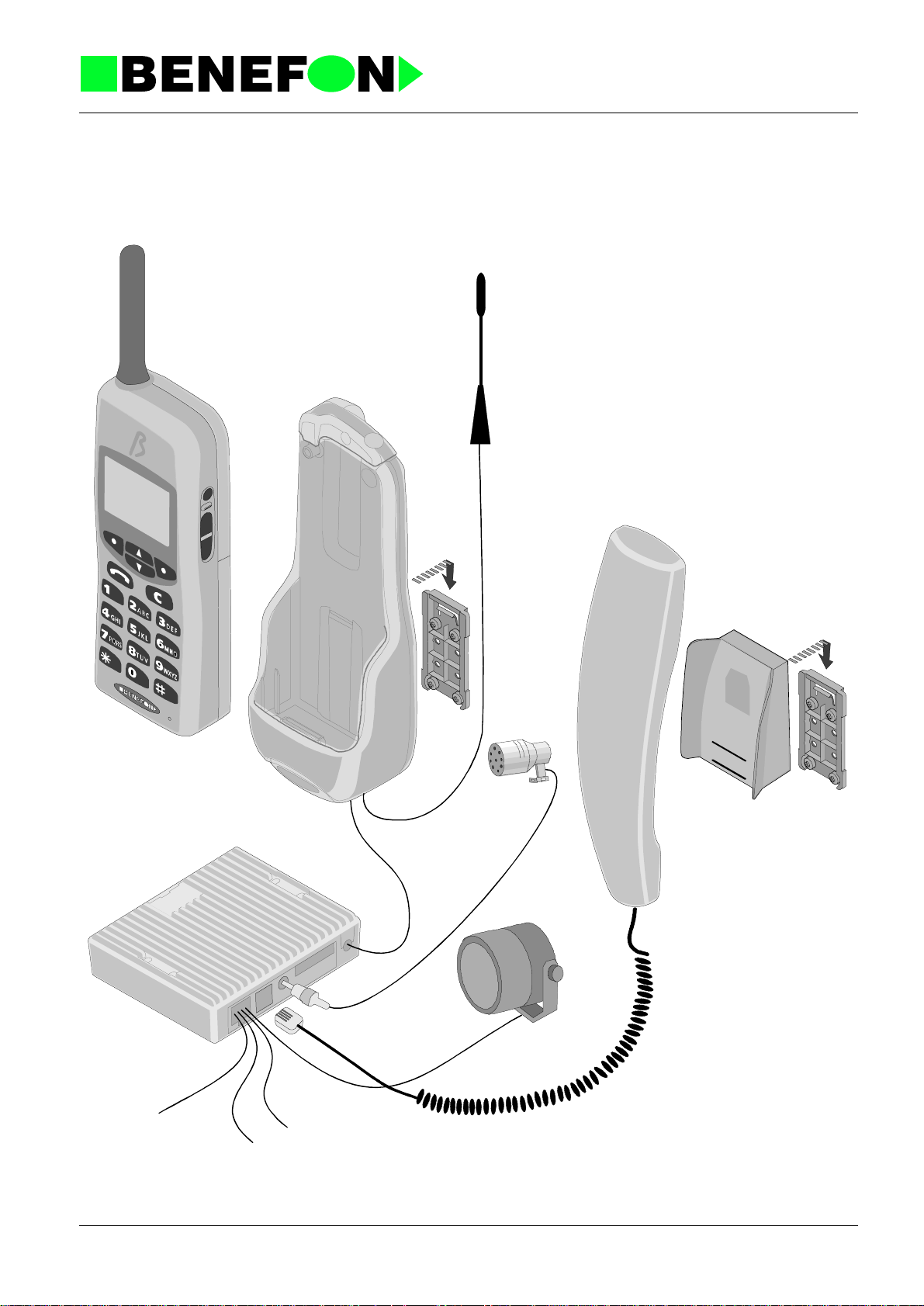
3.2 CAR KIT INSTALLATION
The Car Kit includes a phone holder (KDS-50), a car box (UDH-50), an
antenna, an instal lation base , a hf speaker , a microph one and a cabl e. The Car
Kit sales package al so includes an instal lation mat erial bag, w hich conta ins the
necessary installation equipmen t. On pag e 7 you will find a diagram of
connections explaining how to install the Car Kit.
3.2.1 Antenna
Choose a suitabl e p lac e for t he antenna. It is recom me nd ed tha t you place the
antenna on the roof of the vehicle.
3.2.2 Phone Holder KDS-50
Choose such a place for the phone holder in the vehicle that will be both easy
and safe when using the phone. Reme mber to leave enoug h space for the
antenna plug behind the phone holder. First, fix the installation base to the
place you have chosen, and then install the phone holder in the installa tion
base.
Product: TDP-52-SN3 /
27.1.1999
3.2.3 Microphone
Install the microphone so that it is aimed directly at the user, and comes as
close as possible to the user’s m out h. A good place for th e microphone is n ea r
the rearview mirror where the noise level is lower than, for example, beside a
windshield pillar. It is also possible to install the microphone on a sun visor, but
then it will be inconvenient to use the sun visor an d microphone at the same
time. One alternative would be a swan-neck microphone as it can be placed
closest to the user’s mouth.
3.2.4 Cable
Obtain the necessary +-electricity from a suitable place, preferably directly
from the battery of the vehicle. Connect t he fuse chambe r to the +-wire. You
will find the fuse chamber in the installation material bag. Connect the ground
lead to the frame of the car with a short wire.
3.2.5 External Handset HDS-50
Install the external handset the same way as you installed the phone holder.
6DP_52GB
5
Page 21

3.2.6 Car Box UDH-50
Place the car box out of sight inside the das hboard of the car or to another
place. First, connect the wires to the car box. Install the car box so, that the
heat sink has some space for cooling. The car box has holes which enable you
to fasten the car box with a cabl e tie. The installation mate rial bag also contai ns
adhesive band fasteners.
3.2.7 Hf Speaker
Install the speaker in a suitable place near the floor of the car.To avoid echo
remember to pay attention to the position of the microphone as well.
Product: TDP-52-SN3 /
27.1.1999
6DP_52GB
6
Page 22

A Diagram of Connections
How to install a
cable to a carbox.
to KDS-50
open
Product: TDP-52-SN3 /
27.1.1999
KDS-50
Installation
base
Microphone
HDS-50
Installation
base
UDH-50
fuse
V
4
2
/
2
1
+
,
t
t
a
b
V
PIN Name Color
1 Car Radio Mute (active low) Blue
2 Hf Speaker Grey
3 Ground - Black
4 External Alert (active low) Brown
5 Hf Speaker Grey
6 Vbatt, +12/24 V Red
Car Radio Mute (See the installation
instructions of your car radio)
87
MUTE
+ACC
87A
86
30
85
Battery Voltage
Car Radio
Supply Voltage
86
85
+VB
Car Radio
External
Alert
87A
87
30
Hf Speaker
Mute
External Alert
+VB
+VB
86
87
87A
30
85
Horn
868587A
30
External Alert
Horn
87
+ACC: to the +12 V power terminal
which is energized in the accessory
position of the ignition key
6DP_52GB
External Alert
7
Page 23

Product: TDP-52-SN3 /
27.1.1999
3.3 HF-FUNCTION
Benefon Sigma Gold offers you two differ e nt han ds free -setups for th e Car Kit
and Office Set: the b ackg ro und noise tuning (CAR KIT/OFFICE S ET TUNING)
and MIC-ERP contrast tuning (CAR KIT/OFFICE SET SWING).
3.3.1 CAR KIT TUNING/OFFICE SET TUNING (theory)
You can set up the activation lev el of the microphone by using the CAR KIT
TUNING option. The level is correct when the microphone path is activated by
voice alone, and not, for example, by background noise in your car or office.
The following figur e s hows you the CAR KIT TUNING s etup process. You ca n
set up the OFFICE SET TUNING following the same procedure.
a. If the CAR KIT TUNING is set too high, your voice (1) will not activate the
microphone path properly, and the pe rson at the other end will only hear
interrupted transmission of speech.
(1)
Car kit tuning
50
40
30
6DP_52GB
8
Page 24

Product: TDP-52-SN3 /
27.1.1999
b. If the CAR KIT TUNING has been set up too low, the background noise in
your car (2) will activate the microphone path, and the volume of the HFspeaker will be low.
50
40
30
c. When the CAR KIT TUNING has been set correctly only your voice (1 & 3)
will open the microphone path.
(1 )
(2)
Car kit tuning
(3)
6DP_52GB
50
40
30
Benefon phones have been set in our factory so that they will function in most
cars. The factory setting for the CAR KIT TUNING is 38, and for the OFFICE
SET TUNING 42. The recommended adjustment range is +/- 5 units from the
factory setting.
Car kit tuning
(2 )
9
Page 25

Product: TDP-52-SN3 /
K
K
27.1.1999
3.3.2 CAR KIT SWING/OFFICE SET SWING (theory)
The four-step CAR KIT SWING/OFFICE SET SWING tuning is used to set the
contrast of the microphone amplification/speaker attenuation swing. In the
following figures the swing position while listening to the Car Kit or Office Set is
indicated by a solid line and the position while speaking into Car Kit or Office
Set the indicated by a dotted line.
a. With a tuning value of 4 it is possible to obtain the smallest difference
between the amplification and attenuation of the microphone and speaker. This
means that the connection is almost bidirectional. If the HF-function easily
creates feedback, decrease the value of the CAR KIT SWING/OFFICE SET
SWING. By turning down the volume it is possible to reduce the occurance of
feedback.
MIC
SP
Listening
4
3
2
1
Speaking
b. With a tuning value of 1 it is possible to obtain the greatest difference
between the amplification and attenuation of the microphone and speaker. This
means that the connection is almost unidirectional.
MIC
SP
6DP_52GB
Listening
4
3
2
1
Speaking
The factory setting for the CAR KIT SWING/OFFICE SET SWING is 3.
10
Page 26

Product: TDP-52-SN3 /
27.1.1999
3.3.3 HF-function tuning in practice
You can tune HF-functions two ways: manually or with car kit.
Manual tuning
1. Connect the localbox to your phone, and turn the phone on.
2. Press and the following text w ill appear in the displa y: ***BENEFON***.
* will be flashing in the display.
3. Press , and the following text will appe ar in the display:
HF-FUNCTION
4. Choose SELECT, and the following text will appear in the display:
CAR KIT TUNING [038]. (The figure can be different).
5. Choose CHANGE, and the following text will appear in the display:
CAR KIT TUNING [ ] (026). (The figure can be different).
6. Enter thre e digits and SAVE. Yhe recommended value is between 033
and 043.
Tuning in car kit
7. Choose SELECT, and the following text will appear in the display:
CAR KIT SWING (1...4): [3]. (The figure can be different).
8. Choose SELECT, and the following text will appear in the display:
CAR KIT SWING (1...4): [3]. (3 is blinking)
9. Enter one digit and OK.
1. Connect the localbox to your phone, and turn the phone on.
2. Press and the following text w ill appear in the displa y: ***BENEFON***.
* will be flashing in the display.
3. Connect the hand portable to the car kit
4. Press , and the following text will appear in the di splay:
HF-FUNCTION
5. Choose SELECT, and the following text will appear in the display:
CAR KIT TUNING [038]. (The figure can be different).
6. Choose CHANGE, and the following text will appear in the display:
CAR KIT TUNING [ ] (026). (The figure can be different).
6DP_52GB
7. Drive the car so that you can get a normal back ground noise level. The
figure (026) will be changed a ccording the back ground noice leve l.
8. Enter three digits (back by pressing ) shown in the figure (xxx) and
SAVE. The level will be stored.
11
Page 27

Product: TDP-52-SN3 /
27.1.1999
4.0 SERVICE APPLICATIONS
4.1 BeneWin SCA-50
The BeneWin SCM Program for Windows is designed to facilitate maintenance of
phone numbers and u ser settings on Benefon mo bile phones . You can also use your
phone to carry out the commands in the BeneWin Program, but it is handier to process data using your screen and keyboard - the advantage of the BeneWin Program. For example, all user set tings are disp layed in a single wind ow , wh ich enab les
you to check at a glance your current settings.
Your personal settings and phone numbers stored on the hard disk can be transferred to the mobile phone whenever necessary. When you travel or use a borrowed
phone, your own settings make the phone feel like your own.
The main functions of the BeneWin Program are divided into two windows: the
BeneWin SCM window, in which you can modify the phone numbers, and the User
window, in which you can modify the phone’s user settings.
4.1.1 Installation of BeneWin program
Start Windows.
Insert the BeneWin installation disk in the floppy disk drive of your computer.
In the Program Manager window, choose Run from the File menu.
3DP_52GB
1
Page 28

Product: TDP-52-SN3 /
27.1.1999
In the Command Line box, type the letter A: or B: to indicate your floppy disk
drive, and then type SETUP. For example, A:SETUP.
Click the OK button, and follow the instructions displayed on your screen.
First, accept the location of the source files, which is the floppy disk drive you used
for Setup.
To continue Setup, choose the Continue button. To quit Setup, choose the Exit
Setup button.
Next, the Setup Program will ask you to specify the drive and d irectory in which you
want to install th e BeneWin Program. The Program suggests the following:
C:\BENEW IN. Accept the drive and directory by clicking the Continue button. You
can quit Setup by clicking the Exit Setup button.
The Setup Program create s a BENEWIN directory and within it the necessary subdirectories in drive C of your computer. Setup also creates its own group window in
Program Manager.
3DP_52GB
2
Page 29

Product: TDP-52-SN3 /
27.1.1999
4.1.2 To start the BeneWin program
Connect your phone with a cable to the serial port of your computer, which is called
COM1 or COM2. The serial ports are located in the back of your computer, and more
precise instructions can be found in the manual accompanying the computer. Plug
the flat end of the cable into the connector at the bottom of your phone. When the
cable has been connected and the phone is functioning, you can start the BeneWin
Program.
To start the BeneWin Program, double-click the BeneSCM icon.
If the phone has not been conn ected to the com puter and yo u star t the Program, th e
following error message will appear on the s creen: FATAL COMMUNICATION
ERROR. You will, however, be able to modify the data stored in your computer’s
memory locations by clicking the OK button.
If you use a laptop co mputer m ake sure that t he computer i s not in th e energy savi ng
mode. If so the energy saving mode may prevent the transfer of data from the
phone to computer or vice versa.
After starting up th e Bene Win pro gram w ill gui de you furth er w ith the hel p of an electric manual (Online Help).
3DP_52GB
3
Page 30

4.2 Beneloc
1
2453
A B C D E F
G H I
6
J K L M N O
9
7
P Q R S T U V WXYZ
8
0
M
HFR
Product: TDP-52-SN3 /
27.1.1999
power
5V log
gen
flash
5V log
meter
BeneLoc program is design ed to help serv ice person on tu ning and serv ice purpose.
With BeneLoc Pro gram you will also get W inFlash Pro gram. With W inFlash Progr am
you can change the software to Benefon phones.
Both, BeneLoc and WinFlash pr ogram will need Local Box with service rights to
work.
4.2.1 Installation of Beneloc program
Start Windows. Close all other programs except Program Manager.
Insert Beneloc Installation Disc 1 in the floppy disk drive of your computer. In the
Program Manager window, choose Run from File menu.
Ty pe the letter A: or B: to indicate your floppy disc drive, and then type SETUP.EXE.
For example, A:\SETUP.EXE.
3DP_52GB
Click the OK button, and follow the instructions displayed on your screen.
4
Page 31

The Setup Program will ask you to specify the drive and directory in which you want
to install the Beneloc Program. The Program suggests the following: C:\Bene-
App\BeneLoc. Accept the drive and directory by clicking Next button. You can also
type your own directory for Beneloc Program.
The Setup Program creates all necessary director ies and subdirectories to your
computer. Setup Program also creates its own group window in Program Manager.
WinFlash Program will be installed automatically by Setup Program. You can find
WinFlash.exe from the same directory as the Beneloc: e.g. C:\BeneApp\Win-
Flash.
4.2.2 To start the BeneLoc program
Connect the Servi ce Lo calBox to ser ial por t of you r com puter, which is called COM1
or COM2. The serial ports are usually located in the back of your computer, and
more precise instructions can be found in the manual accompanying the computer.
Product: TDP-52-SN3 /
27.1.1999
Switch off the phone. Plug the cable with flat connec tor into the connector at the bottom of the phone. When the cable has been connected and the phone is switched
on, the phone should be in LOCAL mode. You can test this by pressing arrow button.
There should be ***BENEFON*** on the display, if not, clean connectors and try
again. When phone is in LOCAL mode you can start the BeneLoc Program.
To start the BeneLoc Program, double click the BeneLoc icon.
In the BeneLoc Startup window, f irst sele ct th e correct serial p ort. The n, you ha ve to
select type of the phone. You can also use the Autodetect option. After selection
click OK to start BeneLoc Program. When operating without external power supply
the phone may be on sleep m ode an d r egistr a ti on f ai ls . You can wake up the phon e
by pressing some buttons on the phone.
3DP_52GB
5
Page 32

4.2.3 Using the BeneLoc program
In the main window of the BeneLoc, you will find submenus and buttons. Clicking the
buttons you can go to the submenus.
Product: TDP-52-SN3 /
27.1.1999
Change
Help
Dealer
Service
For changing phone to another similar you do not need to do more than enter into
main menu. It means that this button is not needed. If you are going to change the
tested phone to one having different software in, clicking Cha ng e will start the registration protoco l agai n.
About BeneLoc submenu will tell you version of the BeneLoc Program and also the
state of memory.
About Cellular submenu will show you information of the phone. Type of phones
software, sales date, date of the software, serial number and present tuning values
of the phone. You can not change the tuning values from Help menu.
From Dealer submenu you can make or check programming of the phone. You will
also find the SIS information from Dealer submenu.
You can control the audio lines (for e xample, sw itch Rx a udio and comp ander on/of f)
in the Service m ain me nu. It is a lso possibl e to cont rol the phone to desire d channe l.
There is also possible to change the power of transmitter.
In the Ports submenu is you can see the status of different digital ports. There is
also possible to control some of the output ports.
3DP_52GB
You can read the status of the A/D con verter s fr om th e A/D su bmen u. Se lect 8 di f ferent topics to view. By clicking SCAN AD button The Beneloc will scan A/D the state
of converters continuously. Scanning can stopped by clicking STOP AD.
Memory submenu allows you to make Ram reset.
By clicking Initialize You can clear all LOCAL settings in service menu.
Home button will return you back to main menu.
6
Page 33

Tunings
System
File
Product: TDP-52-SN3 /
27.1.1999
From Tunings main menu you can select different tunings to do. Every tuning have
they own instruction window. Follow given instructions to do tunings. Clicking
START will start tuning. The value will be stored only by clicking SA V E. So me of th e
tunings are chained and you can enter to next phase by clicking NEXT.
You select used mobile phone system from this submenu.
From settings submenu you can manually change settings of the communication
port.
4.3 WinFlash
4.3.1 To start WinFlash
Connect the LocalBox to serial port of your computer, which is called COM1 or
COM2. The seri al ports are usually located in the back of your computer, and more
precise instructions can be found in the manual accompanying the computer.
It is recommended to use external power supply when transferring software to
phone with WinFlash. If it is impossible to use external power supply the battery of
phone must be fully charged.
NOTE !
Before starting WinFlash save the short code memory places and settings of the
phone to disc. You can use Benewin or Beneserv to save the SCM and settings.
Switch off the phone. Plug the cable with flat connec tor into the connector at the bottom of the phone. Start WinFlash by double clicking WinFlash icon. After opening
the main window of the WinFlash select the correct communication port.
3DP_52GB
7
Page 34

4.3.2 Using the WinFlash program
You will find all Benefon mobile phone so ftwares inst alled to you r computer from window in the left side.
Product: TDP-52-SN3 /
27.1.1999
Select the software you want to transfer to phone by clicking it. In the right side window you will find some information of the selected software. Cl ick Execute to start
software transferring to phone. Follow the instructions shown in the screen. Y ou can
reset the phone by removin g the flat co nnecto r from th e phone and attaching it back
again. Be sure that there are no marks on the display before pressing enter.
3DP_52GB
8
Page 35

Product: TDP-52-SN3 (Sigma Gold) /
27.1.1999
5.0 PHONE’S CONSTRUCTION
C
N
2108
V
A
0001
102.ds4
dg0
F
785
725
0
0
Y
Y
e
O
O
od
C
5
5
D
078
072
D
D
O
O
on
rsi
e
V
dic
r
o
oland
P
N
8
06
10
0
12
14
08
C
M
837
0
C
M
lue
B
24
08
08
08
08
C
C
C
C
M
M
M
M
40
841
839
838
8
0
0
0
0
C
C
C
C
M
M
M
M
n effect
en
y
ode
o
re
re
ed
W
G
G
R
M
A
0062
B
08
C
e
M
od
C
836
A
0
C
M
0
e
od
007
C
A
Y
rsion
e
V
land
o
ic, P
ord
N
lor
o
C
lack
B
7DP_52GB
A
F
502
M
1
1
Page 36

5.1 LOGIC / AUDIO
OA0701 Processor
Processor
5.1.1 General
The entire radio audio and processor functions are found within a single
PA0700 board, through which all other modules are connected. Only the RF
signals have a different path and the keyboard has a different unit.
The processor controls the audio and radio modules, internal devices and
external accessories.
Product: TDP-52-SN3 (Sigma Gold) / OA0701 Processor
27.1.1999
The processor includes:
CPU 68HC11A1 8-bit, 8 A/D, 512*8 EEPROM, 256*8 RAM, I/O
PROM 28F020 256*8 EEPROM, program memory
RAM 62256 8K*8 CMOS RAM, numb er memory
ASIC IA8001
SIS 68HC11A8
32 pcs out and 14 pcs inp , 3 series out, 3 an alog
out, frequency counter, clock
SIS function, 8k ROM, 512*8 EEP ROM, 256*8
RAM
4A0701GB.__1
2
Page 37

5.1.2 Connectors:
5.1.2.1 RF-Module, V102 20 pin connector
1 SSDATA RX and TX data to the splitter 0/5V
2 SSCLK RX and TX data clock 0/5V
3 SSLE RX and TX divider enable pulse 5V
4 SRX_REG rx vco start up 5V
5 STX_REG tx vco start up 5V
6SAFC
7 SSNTC temperature data, analog 0-5V
8 SRXAUDIO RX audio signal 220 mVrms
9 SRSSI RX signal strength indicator, analog 0-5V
10 GND ground
11 S450K 450k Hz for AFC measurement approx 1Vpp
12 GND ground
13 SDTUNE not function
14 SSPARE not function
15 VB power supply from the battery 6V
16 VB
17 VB
18 STXBIAS TX initiate, 0V = TX OFF 0/5V
19 STXPWR TX power control, analo g 0-5V
20 STXAUDIO TX audio signal 220 mVrms
frequency compensation control
voltage
Product: TDP-52-SN3 (Sigma Gold) / OA0701 Processor
27.1.1999
approx 2.5V
5.1.2.2 Keyboard module + systemconnector lines
V101 40 pin connector
1 VB power supply from battery 6V
2VB
3VB
4VB
5VB
6 EXTMIC external audio from the microphone 400 mVrms
7 EXTERP
8 XCADET carbox identification 0/5V
9 I2CINT i2c interrupt, ra dio input 0/5V
10 SGL i2c clock 0/5V
11 SDA i2c data 0/5V
12 TXD rs232 out 0/5V
13 RXD rs232 in 0/5V
14 XEXTIO reserve 0/5V
15 GND ground
external audio to the speaker amplifier
220 mVrms
4A0701GB.__1
3
Page 38

Product: TDP-52-SN3 (Sigma Gold) / OA0701 Processor
27.1.1999
16 GND
17 GND
18 GND
19 GND
20 GND
21 XKEYINP0 key matrix input 0/5V
22 XKEYINP1
23 XKEYINP2
24 XKEYINP3
25 XKEYINP3
26 XKEYOUT0 key matrix output 0/5V
27 XKEYOUT1
28 XKEYOUT2
29 XKEYOUT3
30 XCHGIND charging voltage indicator 0/5V
31 XBMEM
input memory dat a -line from the ba ttery
0/5V
32 nc
33 nc
34 MICINPUT microphone-line
35 nc
36 XISIGN battery voltage course indicator 0/5V
37 KEYLEDVB voltage for the led of keyboard 6V
38 IVBDET battery current indicator 0-5V
39 V-PROG battery charging voltage
40 V-PROG
4A0701GB.__1
4
Page 39

5.1.2.3 Display Module, A101
1 VCC supply voltage 5V
2 RES reset-line 0/5V
3 CSI display data input 0/5V
4AO
5 SCL clock line for data 0/5V
6SI
7 GND ground
8 CONT not function
9GND
10 LED supply voltage for led of display
11 KEYOUT1 key matrix output (volume key -) 0/5V
12 KEYINP4
13 KEYINP4 key matrix input (volume keys+/-) 0/5V
14 KEYOUT0 key matrix output (volume key +) 0/5V
15 PWRKEY powerkey
16 GND
Product: TDP-52-SN3 (Sigma Gold) / OA0701 Processor
27.1.1999
5.1.2.4 Answer Module, I101
1 VCC supply voltage 5V
2 REC record control 0/5V
3 GND ground
4PLAYE 5V
5 PLAYL play control 0/5V
6 ANAIN audio input
7 GND1 ground
8 VCCA supply voltage 5V
9 SP+ audio output
10 GND2 ground
5.1.3 Circuit Diagram
The processor and audio circuit diagram is split into five parts. Signals in the
circuit diagrams have been given names, and signals with the same name are
connected between diagrams.
4A0701GB.__1
5
Page 40

5.1.3.1 Circuit Diagram Contents
OA0701A module connector pins
OA0701B power supply
OA0701C cpu, ASIC, RAM, EPROM
OA0701D audio parts
OA0701E SIS-function
5.1.4 Functions
5.1.4.1 CPU
I304 is itself a processor circuit. It is comprised of CPU, 512*8bit EEPROM,
timers, A/D converters, and both series- and parallel I/O lines. The clock
oscillator is located in the audio circuit and provides the CPU with a 7.2 MHz
clock signal. The CPU divides this by 4 to get timing signal E.
Product: TDP-52-SN3 (Sigma Gold) / OA0701 Processor
27.1.1999
When the processor is oper atin g, RESET = 5V, VC C = 5V , E = 1 .8 Mhz, AS, R /
W and A0...A15 pulses should be 0/5V (no intermediate values, only 0 or 5V).
4A0701GB.__1
6
Page 41

5.1.4.2 Memories
Memory and external I/O-circuit address coding is done with the ASIC circuit
I305. The circuit options CSR, CSP, and OE are 0-active.
The program memory is in 256k*8 EPROM. The program uses the addre sses
2100H...FFFFH. Page selection makes available another similar memory
block.
RAM-memory is 8k*8 CMOS RAM at the addresses 0000H...1FFFH. RAM
receives its power supply from its own regulator which is always operating,
even when the radio is in the OFF state.
5.1.4.3 The Modem
The FFSK modem is located in the audio circuit. The modem is connected to
the CPU by a series line, input to synchronised port, and transmission is
controlled by an ASIC series output. The modem gives a 1200 Hz signal
RXCLK to the processor and TXCLK to ASIC. There is a data detector within
the modem, the speed of which is controlled by C438.The CPU A/D converter
measures the level of acceptance from ERPDET line. The same detector also
serves to control the HF function.
Product: TDP-52-SN3 (Sigma Gold) / OA0701 Processor
27.1.1999
5.1.4.4 AFC
The AFC function is performed by an internal ASIC frequency counter. A 450
kHz intermediate frequency is amplified to a square-wave form by Q305. The
frequency is adjusted by ASIC pulse frequency modulated signal D/A 0, which
is integrated by C378. This approx. 2.5V DC voltage is fed to the synthesiser
AFC pin.
5.1.4.5 Sleep Timer
The phone puts the central functions to sleep for a time. Although everything
seems normal to the user, most of the functions are closed down. The radi o
and audio units are closed down completely. The processor still has a power
supply, but the processor is halted and has minimal power consumption. Only
the ASIC circuit sleep timer and its 32 kHz crystal oscillator remain in active
mode. The phone is "woken up" by interrupting the sleep timer or by changing
the keyboard state. The sleep timer 32 kHz clock freqency is produced by the
oscillator made by crystal X305.
5.1.4.6 Warm Start
C352 and R352 measure the length of a voltage break. The voltage drops
during a break, after which it is measured by the A/D convertor. The time
constant is approx. 10 s . Thus a "warm start" is detected.
4A0701GB.__1
7
Page 42

5.1.4.7 RESET
The processor voltage regulator ERROR output resets (stops) the processor
and zeroes the c ontrols when the battery voltage drops below 5V. When th e
voltage rises again, the processor restarts.
5.1.4.8 Power Switch
The power switch (PWRKEY) is grounded, and directs the regulator I201 to
conduct when pressed. The program commences and checks the PWRSW line
to ensure that the switch is being pressed, and sets hold on the regulator for
the PWRON li ne. W he n the switch is depressed for a l ong er t im e , th e pr og ram
directs power to the PWROFF line. During a sh ort voltage break, C21 1 and
R211 remember the previous control, i.e. fet Q202 conducts again when the
voltage is restored within 10 seconds. The switch-fet also serves as a watchdog should the voltage drop or proc essor error-state continue; after 10
seconds, the radio will shut down completely.
Product: TDP-52-SN3 (Sigma Gold) / OA0701 Processor
27.1.1999
Note! The RAM and ASIC circuits have their own regulator connected to the
battery to ensure an uninterrupted power supply. RAM power supply is
ensured during a battery-pack change by the battery B201.
5.1.4.9 Battery Voltage Measurement
The battery voltage is measured by an A/D converter. The converter 256 step
conversion scale is not sufficient as it stands, so the measured range is
restricted to 5...8V by the operational amplifier I303. The reference voltage for
the measurement is provid ed by the processor r egulator 5V supply. C alibra tion
is done by the program against a precisely known battery voltage.
5.1.4.10 I/O ports
The ASIC I/O ports PA...PF are 8-bit hold circuits. DATA is fed to the
addressed output. When the RESET line is down (0V) all the ASIC ports are
zeroed (0V). As RESET rises agai n, all of the tw o-way I/O ports are i nputs until
the program sets them to the desired state. With the radio in OFF state,
RESET is down so all of the controls are also dow n although ASIC is still
provided with operational voltage (VRAM).
5.1.4.11 SIS
4A0701GB.__1
SIS functions are provided by a mask-programmed single chip processor I503
(68HC11A8). It commu nicates with th e host processor vi a ASIC with an RS232
bus (5V levels). The circuit operation is not externally visible as it is a singlechip solution. User specific information is stored in EEPROM which CANNOT
be read from outside the chip. All external attempts to read the information
clear both EEPROM and RAM (fill with FF).
8
Page 43

5.1.4.12 Power Adjustment
The transmitter control logic switches TX power and also adjusts it to the
correct level. The STX_REG signal sets the transmitter to ready mode. Power
is controlled by the ASIC analog output D/A 1. It is a pulse frequency
modulated output which is converted to a DC voltage by integrating it with
C379. 0V corresponds to "no power" state, and 5V to maximum transmitter
power. The power l evels are calibrat ed by the program at the source of
measurement.
5.1.4.13 Charging Control
The charger is con trol led by th e pro gram. The char ger is detect ed by a volta ge
at the SV-CHG pin. The charging current (0...1,5A) is controlled by an analog
(0...5V) CHGCONT signal which comes from the ASIC D/A 2 pulse frequency
output. Charging is governed by the battery and radio temperatures, battery
voltage, and time measurement.
Product: TDP-52-SN3 (Sigma Gold) / OA0701 Processor
27.1.1999
5.1.4.14 Temperature Measurement
The radio has two separate temperature sensors, one within the battery pack,
and the other within the radio module. Inside the radio the NTC resistor R316
voltage is measured by the processor A/D converter. This value is converted
by a programmed table to a temperature reading.
5.1.4.15 Real-time Clock
A real-time clock is provided within ASIC to give the time and date. The alarm
function can also be programmed to the ALARM pin. This will initiate the
processor regulator and thus also the radio although it is in OFF state.
The ASIC circuit has a continuous power supply and the 32 kHz clock crystal
runs constantly. Not even the RESET line stops the clock. If the power supply
has dropped too low, the clock will need to be reset with the radio buttons (from
the menu).
5.1.4.16 Answer Module
Answer module can save a maximum 16 second message. The message can
be recorded from the microphone, external microphone or RX-audio. Th e
message can be sent to the earphone, external earphone or TX-audio.
4A0701GB.__1
9
Page 44

Audio
5.1.5 Function Description
OA0700 Audio
The audio module is comprised of the f ollowing functions:
1. TX-audio signal handling
2. RX-audio signal handling
3. Fii signal handling
4. FFSK modem
5. DTMF generator/receiver
6. Signal lev el detectors
Product: TDP-52-SN3 (Sigma Gold) / OA0700 Audio
27.1.1999
7. Compander
8. Expander
9. Buzzer
The audio functions are mainly located in a single circuit AK2339. This chip
from AKM is controlled by a serialbus. It is possible to shut down parts of the
circuit, one block at a time to minimise power consumption.
5.1.6 TX-audio
The input from the microphone is fed to the audio circuit I405 pin 61, which is
an operational amplifier (AMP1) inverting input. The operational amplifier gain
is set by resistors R413 and R416. The amplifier is connected as a low pass
filter. After the amplifier is the microphone switch and then summing junction of
MIC input signal, EXTMIC input signal and transmit DTMF signal. VR1 is a
programmable amplifier, which sets the microphone signal (se ns i tivity) to the
correct level. After VR1 comes band-pa ss filter for transmitting the voice sig nal.
After the TXBPF is the summing junction (AMP6) of the tx signal and transmit
answer signal (ANAOUT). TXDET is the transmit voice signal detection circuit
which works as a full wave rectifier. Next comes ATT1 which is an attenuate
circuit to set the transmit signal level in the HF-mode. COMP is the compressor
circuit. Compress the transmitting signal amplitude with square root law. It can
be hypassed. The linearity is adjustable by the control register CVR. Next is
VR2, normal deviation gain control circuit to set the signal level. The P/E &
LIMIT pre-emphasi s circuit and li miting ci rcuit, em phasize the high er fre quency
component of the signal in order to improve the signal-to-noise ratio of
modulated signal. This block includes a limiting circuit for signal amplitude in
order to confine the maximum deviation of the transmit modulated signal.
TXLPF is the low pass filter to reject the higher frequency component on the
4A0701GB.__1
10
Page 45

transmit signal. VR3 is a maximum deviation gain control circuit to set the
transmit signal level. After the VR3 comes switch TXAUDON, which mutes the
tx-audio signal using the TXMUTE control. From the switch, the signal is fed to
the summing junction (ADD3) of the tx-audio signal, FFSK signal and Fiisignal. Next comes VR4 gain control circuit to set. SMF1 is smoothing filter for
tx-audio signal. The tx-audio signal is then fed to the V102 connector pin 20.
5.1.7 RX-Audio
The rx-audio signal coming from the receiver through the V102 pin 8 is fed to
the audio circuit I405 pin 23. Inside the circuit, the signal is fed to the
operational amplifier (AMP2 ) inverting input. The amplifier gain is set by
resistors R440 and R441. The signal is next passed through an anti-aliasign
filter. VR5 is a gain control circuit to set the rx-audio signal to the correct level.
Next comes de-emphasis (D/E) circuit. Equalize the pre-empassized rx-audio
signal. The signal p asses from the D /E thro ugh th e switch RXAU DON. R XBPF
is the band-pass filter for the rx-audio signal. RXDET is the rx-audio signal
detection circuit. This circuit works as a full wave rectifier. After the RXBPF
comes expander circuit (EXP ). Expand the rx-audi o signal amplit ude. It can be
bypassed. The linearity is adjustable by the control register EVR. VR6 is a gain
control circuit to set the rx-audio signal to the correct level. After VR6 comes
the RXMUTE switch, which is operated by the RXMUTE control. ADD4 is the
summing junction of the rx-audio signal, external signal (not used), DTMF
signal and transmit signal. VR10 is the volume control circuit to set the level of
earphone and external earphone s. The rx-audio signal is connected through
the receiver driver (RECAMP) to the earphone.
Product: TDP-52-SN3 (Sigma Gold) / OA0700 Audio
27.1.1999
5.1.8 FII Signal
The NMT system uses the FII signal to check the radio path quality. This
approx. 4kHz signal is split from the rx-audio signal after the VR5 and is filtered
through the band- pass filter (FB PF). VR7 sets t he FII signal to the correct l evel.
Switch FILOOPON can be operated by the FIION control, to be summed with
the tx-audio signal before the VR4.
5.1.9 FFSK Modem
The FFSK data signal from FFSK modulator to be transmitted is passed
through the FFSK low-pass filter and pre-emphasis (FFSKP-EM) to the VR9,
which adjusts its level. The data signal is switched using switch FFSKTXON.
The data signal is summed with the tx-audio signal by the ADD3.
The received data si g nal is spl it fr om th e rx-audio signal a fte r the de-emphasis
circuit. The data signal is fed through the FFSK band-pass filter to the FFSK
demodulator and FFSK data detector.
FFSK DET block. The block works to judge the FFSK signal existence by
comparing the amplitude of the noise reduced FFSK signal and the provided
4A0701GB.__1
11
Page 46

Product: TDP-52-SN3 (Sigma Gold) / OA0700 Audio
27.1.1999
detection level standard. Once the detector judges a valid FFSK signal, ’H’
signal is put out on the FFSKDET pin (pin43). The data detector speed is
determined by the external condensator C438.
FFSK DEMOD. To recover 1200bps receive data and clock from the FFSK
signal fed on DEM1 pin.
The modem is connected to the CPU by series lines, the receiver to a
synchronised gate, and transmission is directed to an ASIC series output. The
modem provides a 1200 Hz clock signal RXCLK to the processor and TXCLK
to ASIC.
5.1.10 The DTMF Generator/Receiver
The DTMF generator provides all sixteen standard DTMF tones, and each
individual frequen cy separately. The g enerator is used to produce both key and
alarm tones and enable numeric message transmission during a call.
Key and alarm tones are taken from the generator to switch DTMFRXON and
is summed with the rx -audio signal. Key ton es ar e con ne c ted to ear p hone and
external earphones.
When transmitting a numeric message, the DTMF tones produced by the
generator are fed through the VR8, which set the DTMF signal level to the
switch DTMFTXON, and then the signal is summed with the tx-audio signal.
The DTMF receiver takes in numeric messages sent to the phone. The route to
the DTMF receiver splits from the rx-audio signal after the summing junction
ADD4.
5.1.11 Signal level detectors
Audio signal level detectors are required for the HF-function to measure the
transmitted and received audio signal level, and to study the data signal level.
Measurement is done by rectifying the signal, and the resultant DC voltage is
read by a phone’s prosessor A/D convert er. TXDET is at the transmis sio n side
detector and RXDET is at the receiver side detector.
5.1.12 Compander/Expander
Compander and expander units are included in audio asic I405 and can be
controlled by registers.
5.1.13 Alarm buzzer
Tones for the internal alarm tones are provided by the DTMF generator. The
internal alarm tones path way is DTMF generator, VR8, switch DTMFRXON,
summing junction ADD4, VR11, AMP5 and buzzer. The buzzer volume is
controlled by t he DA3.
4A0701GB.__1
12
Page 47

Product: TDP-52-SN3 (Sigma Gold) / OA0700 Audio
27.1.1999
5.1.14 Audio signals for answer module
The record signal comes from the tx side through the switch AUDLOOPON,
ADD4, VR11 and AMP5 to answer module I101. The audio s ignal from the
answer module comes to the summing junction AMP6.
5.1.15 The other in audio asic (I405)
OSC is the main oscillator and clock divider for the prosessor.
CLKBUF is clock buffer generate clock out from main clock.
INTERFACE & DATA REGISTER is a 16 bit address/data serial interface
circuit.
BIAS is bias current generator for amplifiers.
TIMER is an 8 bit timer (not used).
DA1, DA2, DA3 are 8 bit linear DA converters.
4A0701GB.__1
13
Page 48

Product: TDP-52-SN3 (Sigma Gold) / OA0701 Proc./
27.1.1999
5.1.16 Parts list OA0701
OA0701 Proc./Audio
CODE PART DESCRIPT. VALUE MANUF. TYPE
OO0521 A101 Matrix display module 5V Alps LSU4Y4021A
AE0017 A400 Buzzer 13x11x3mm 1.5V/80mA Primo MB-11A-K
AE0016 A401 Earphone Ceramic receiver Primo CR9II-35
AB0002 B201 Lithium battery 3V 39mAh Rayovac BR 1225SM-B
CF0223 C108 SMD capasitor 22 nF 10% 50 V X7R Philips
CF0223 C175 SMD capasitor 22 nF 10% 50 V X7R Philips
CF0223 C176 SMD capasitor 22 nF 10% 50 V X7R Philips
CF0223 C202 SMD capasitor 22 nF 10% 50 V X7R Philips
CF0223 C205 SMD capasitor 22 nF 10% 50 V X7R Philips
CU1106 C206 SMD tantal 10uF/16V AVX TAJB106M016R
CU1226 C208 SMD tantal 22uF/6.3V 20% 6x3.2mm Matsushita ECSTOJC 226R
CF0223 C209 SMD capasitor 22 nF 10% 50 V X7R Philips
CU1106 C211 SMD tantal 10uF/16V AVX TAJB106M016R
CF0101 C213 SMD capasitor 100 pF 5% 50 V NP0 Philips
CF0101 C214 SMD capasitor 100 pF 5% 50 V NP0 Philips
CU1106 C215 SMD tantal 10uF/16V AVX TAJB106M016R
CF0223 C216 SMD capasitor 22 nF 10% 50 V X7R Philips
CF0223 C305 SMD capasitor 22 nF 10% 50 V X7R Philips
CF0102 C306 SMD capasitor 1 nF 5 % NP0 Philips
CF0223 C307 SMD capasitor 22 nF 10% 50 V X7R Philips
CF0223 C308 SMD capasitor 22 nF 10% 50 V X7R Philips
CF0223 C309 SMD capasitor 22 nF 10% 50 V X7R Philips
CF0223 C310 SMD capasitor 22 nF 10% 50 V X7R Philips
CF0223 C315 SMD capasitor 22 nF 10% 50 V X7R Philips
CF0223 C316 SMD capasitor 22 nF 10% 50 V X7R Philips
CF0223 C334 SMD capasitor 22 nF 10% 50 V X7R Philips
CF0223 C351 SMD capasitor 22 nF 10% 50 V X7R Philips
CU1106 C352 SMD tantal 10uF/16V AVX TAJB106M016R
CF0223 C353 SMD capasitor 22 nF 10% 50 V X7R Philips
CF0223 C360 SMD capasitor 22 nF 10% 50 V X7R Philips
CF0103 C365 SMD capasitor 10 nF 10% 50 V X7R Philips
CF0220 C367 SMD capasitor 22 pF 5% 50 V NP0 Philips
CF0220 C368 SMD capasitor 22 pF 5% 50 V NP0 Philips
CU1105 C378 SMD tantal 1uF/16V AVX TAJR105M016R
CU0334 C379 SMD tanlat 0.33uF/20V/10% AVX/KYO-
CER
CU1105 C380 SMD tantal 1uF/16V AVX TAJR105M016R
CF0223 C403 SMD capasitor 22 nF 10% 50 V X7R Philips
CU3475 C411 SMD tantal 4.7uF/10V 20% AVX TAJA475M010R
CF0101 C412 SMD capasitor 100 pF 5% 50 V NP0 Philips
CD0473 C413 SMD capasitor 47 nF 10% 50 V X7R Philips
CF0222 C414 SMD capasitor 2.2 nF 5% 50 V NP0 Philips
CF0223 C420 SMD capasitor 22 nF 10% 50 V X7R Philips
CD0223 C422 SMD capasitor 22 nF 10% 50 V X7R Philips
CF0223 C424 SMD capasitor 22 nF 10% 50 V X7R Philips
CF0223 C425 SMD capasitor 22 nF 10% 50 V X7R Philips
CF0223 C426 SMD capasitor 22 nF 10% 50 V X7R Philips
CD0473 C428 SMD capasitor 47 nF 10% 50 V X7R Philips
CH0105 C429 SMD capasitor 1uF/-20/+80%/16V TaiyoYuden EMK212 F105Z00T
CF0220 C431 SMD capasitor 22 pF 5% 50 V NP0 Philips
CF0223 C432 SMD capasitor 22 nF 10% 50 V X7R Philips
CU1105 C434 SMD tantal 1uF/16V AVX TAJR105M016R
CU1105 C435 SMD tantal 1uF/16V AVX TAJR105M016R
CU1105 C436 SMD tantal 1uF/16V AVX TAJR105M016R
CD0473 C438 SMD capasitor 47 nF 10% 50 V X7R Philips
TAJR334K020R
4A0701GB.__1
14
Page 49

Product: TDP-52-SN3 (Sigma Gold) / OA0701 Proc./
27.1.1999
CODE PART DESCRIPT. VALUE MANUF. TYPE
CH0105 C440 SMD capasitor 1uF/-20/+80%/16V TaiyoYuden EMK212 F105Z00T
CD0104 C443 SMD capasitor 100 nF 10% 50 V X7R Philips
CD0104 C444 SMD capasitor 100 nF 10% 50 V X7R Philips
CH0105 C446 SMD capasitor 1uF/-20/+80%/16V TaiyoYuden EMK212 F105Z00T
CF0331 C447 SMD capasitor 330 pF 5% 50 V NP0 Philips
CF0223 C451 SMD capasitor 22 nF 10% 50 V X7R Philips
CD0223 C452 SMD capasitor 22 nF 10% 50 V X7R Philips
CF0220 C458 SMD capasitor 22 pF 5% 50 V NP0 Philips
CF0220 C459 SMD capasitor 22 pF 5% 50 V NP0 Philips
CF0221 C502 SMD capasitor 220 pF 5% 50 V NP0 Philips
CF0223 C510 SMD capasitor 22 nF 10% 50 V X7R Philips
DS1070 D201 SMD diode pair 70V/100mA common cathode Philips BAV 70W
DS1070 D202 SMD diode pair 70V/100mA common cathode Philips BAV 70W
DS1070 D203 SMD diode pair 70V/100mA common cathode Philips BAV 70W
DY0054 D205 S hottky diode Philips BAT 54
DS1070 D206 SMD diode pair 70V/100mA common cathode Philips BAV 70W
DS1056 D301 SMD diode pair 70V/100mA common anode P hilips BAW 56W
DS1099 D401 SMD diode pair 70 V 200 mA Philips BAV 99W 115
OO0020 I101 Answer module Elcoteq
IR7250 I201 Regulator 5V /100mA TexasInstr TPS7250QDR
IR8850 I202 SMD regulator 5V/30mA SeikoInstr S-8850AF-TF
IM0256 I301 SRAM CMOS 32kx8 5V Samsung KM62256CLTG-10L
IM2010 I302 Flash memory 2Mb Intel E28F020-150
IA7550 I303 Single op.amp. Toshiba TA 75S01F-TE85L
IP6810 I304 Prosessor (Peippo) 512 EEPROM, 8A/D, no ROM Motorola MC68HC11A1FU
IG8001 I305 ASIC SeikoEpson SLA919SF1V
IX2339 I405 Audio processor CMOS base band pros AsahiKasei AK2339
IP6832 I503 Processor (SIS) 8k ma skP ROM,512EE PROM Motorola MC68HC11A8 FU
LF0003 L150 EMI filter 50MHz=65ohm +-40% Murata BLM11B141DP TM00LF0003 L151 EMI filter 50MHz=65ohm +-40% Murata BLM11B141DP TM00LF0003 L160 EMI filter 50MHz=65ohm +-40% Murata BLM11B141DP TM00QS0858 Q101 S MD transistor PNP 0.1A/30V hFE 125-800 Philips BC858BW
QS0848 Q102 S MD transistor NPN 0.1A/30V hFE 110-800 Philips BC848BW, 115
QS0858 Q105 S MD transistor PNP 0.1A/30V hFE 125-800 Philips BC858BW
QS0848 Q106 S MD transistor NPN 0.1A/30V hFE 110-800 Philips BC848BW, 115
QF7002 Q202 SMD n-channel FET 60V 0.115A Rds7.5 Siliconix 2N7002-T1
QS0848 Q203 S MD transistor NPN 0.1A/30V hFE 110-800 Philips BC848BW, 115
QS0848 Q210 S MD transistor NPN 0.1A/30V hFE 110-800 Philips BC848BW, 115
QS0848 Q301 S MD transistor NPN 0.1A/30V hFE 110-800 Philips BC848BW, 115
QS0848 Q302 S MD transistor NPN 0.1A/30V hFE 110-800 Philips BC848BW, 115
QS0848 Q305 S MD transistor NPN 0.1A/30V hFE 110-800 Philips BC848BW, 115
QF7002 Q401 SMD n-channel FET 60V 0.115A Rds7.5 Siliconix 2N7002-T1
RF0103 R101 SMD resistor 10 k 5% 0.125 W Kamaya
RF0103 R102 SMD resistor 10 k 5% 0.125 W Kamaya
RF0472 R103 SMD resistor 4.7 k 5% 0.125 W Kamaya
RF0472 R104 SMD resistor 4.7 k 5% 0.125 W Kamaya
RF0103 R105 SMD resistor 10 k 5% 0.125 W Kamaya
RF0104 R106 SMD resistor 100 k 5% 0.125 W Kamaya
RF0104 R107 SMD resistor 100 k 5% 0.125 W Kamaya
RF0104 R108 SMD resistor 100 k 5% 0.125 W Kamaya
RF0101 R109 SMD resistor 100 R 5% 0.125 W Kamaya
RF0103 R110 SMD resistor 10 k 5% 0.125 W Kamaya
RF0105 R111 SMD resistor 1 M 5% 0.125 W Kamaya
RF0102 R121 SMD resistor 1 k 5% 0.125 W Kamaya
RF0102 R122 SMD resistor 1 k 5% 0.125 W Kamaya
RF0102 R123 SMD resistor 1 k 5% 0.125 W Kamaya
RF0102 R124 SMD resistor 1 k 5% 0.125 W Kamaya
RF0102 R125 SMD resistor 1 k 5% 0.125 W Kamaya
RF0102 R126 SMD resistor 1 k 5% 0.125 W Kamaya
RF0102 R127 SMD resistor 1 k 5% 0.125 W Kamaya
4A0701GB.__1
15
Page 50

Product: TDP-52-SN3 (Sigma Gold) / OA0701 Proc./
27.1.1999
CODE PART DESCRIPT. VALUE MANUF. TYPE
RF0102 R128 SMD resistor 1 k 5% 0.125 W Kamaya
RF0102 R129 SMD resistor 1 k 5% 0.125 W Kamaya
RF0101 R130 SMD resistor 100 R 5% 0.125 W Kamaya
RF0101 R131 SMD resistor 100 R 5% 0.125 W Kamaya
RF0101 R132 SMD resistor 100 R 5% 0.125 W Kamaya
RF0103 R135 SMD resistor 10 k 5% 0.125 W Kamaya
RF0103 R136 SMD resistor 10 k 5% 0.125 W Kamaya
RF0102 R141 SMD resistor 1 k 5% 0.125 W Kamaya
RF0102 R142 SMD resistor 1 k 5% 0.125 W Kamaya
RF0102 R143 SMD resistor 1 k 5% 0.125 W Kamaya
RF0102 R144 SMD resistor 1 k 5% 0.125 W Kamaya
RF0102 R145 SMD resistor 1 k 5% 0.125 W Kamaya
RF0102 R146 SMD resistor 1 k 5% 0.125 W Kamaya
RF0102 R147 SMD resistor 1 k 5% 0.125 W Kamaya
RF0102 R148 SMD resistor 1 k 5% 0.125 W Kamaya
RF0102 R149 SMD resistor 1 k 5% 0.125 W Kamaya
RF0102 R150 SMD resistor 1 k 5% 0.125 W Kamaya
RF0102 R151 SMD resistor 1 k 5% 0.125 W Kamaya
RF0101 R154 SMD resistor 100 R 5% 0.125 W Kamaya
RF0222 R155 SMD resistor 2.2 k 5% 0.125 W Kamaya
RF0102 R157 SMD resistor 1 k 5% 0.125 W Kamaya
RF0102 R158 SMD resistor 1 k 5% 0.125 W Kamaya
RF0102 R159 SMD resistor 1 k 5% 0.125 W Kamaya
RF0102 R160 SMD resistor 1 k 5% 0.125 W Kamaya
RF0102 R161 SMD resistor 1 k 5% 0.125 W Kamaya
RF0102 R163 SMD resistor 1 k 5% 0.125 W Kamaya
RF0102 R164 SMD resistor 1 k 5% 0.125 W Kamaya
RF0102 R165 SMD resistor 1 k 5% 0.125 W Kamaya
RF0102 R166 SMD resistor 1 k 5% 0.125 W Kamaya
RF0331 R170 SMD resistor 330 R 5% 0.125 W Kamaya
RF0103 R171 SMD resistor 10 k 5% 0.125 W Kamaya
RF0103 R172 SMD resistor 10 k 5% 0.125 W Kamaya
RF0104 R175 SMD resistor 100 k 5% 0.125 W Kamaya
RF0104 R176 SMD resistor 100 k 5% 0.125 W Kamaya
RF0104 R177 SMD resistor 100 k 5% 0.125 W Kamaya
RF0224 R201 SMD resistor 220 k 5% 0.125 W Kamaya
RF0103 R202 SMD resistor 10 k 5% 0.125 W Kamaya
RF0683 R203 SMD resistor 68 k 5% 0.125 W Kamaya
RF0102 R204 SMD resistor 1 k 5% 0.125 W Kamaya
RF0103 R205 SMD resistor 10 k 5% 0.125 W Kamaya
RF0473 R206 SMD resistor 47 k 5% 0.125 W Kamaya
RF0104 R207 SMD resistor 100 k 5% 0.125 W Kamaya
RF0223 R208 SMD resistor 22 k 5% 0.125 W Kamaya
RF0104 R210 SMD resistor 100 k 5% 0.125 W Kamaya
RF0105 R211 SMD resistor 1 M 5% 0.125 W Kamaya
RF0223 R212 SMD resistor 22 k 5% 0.125 W Kamaya
RF0101 R215 SMD resistor 100 R 5% 0.125 W Kamaya
RF0222 R220 SMD resistor 2.2 k 5% 0.125 W Kamaya
RD0470 R221 SMD resistor 47 R 5% 0.125 W Kamaya
RF0104 R301 SMD resistor 100 k 5% 0.125 W Kamaya
RF0104 R302 SMD resistor 100 k 5% 0.125 W Kamaya
RF0103 R303 SMD resistor 10 k 5% 0.125 W Kamaya
RF0103 R304 SMD resistor 10 k 5% 0.125 W Kamaya
RF0103 R305 SMD resistor 10 k 5% 0.125 W Kamaya
RF0100 R307 SMD resistor 10 R 5% 0.125 W Kamaya
RF0392 R308 SMD resistor 3.9 k 5% 0.125 W Kamaya
RF0104 R309 SMD resistor 100 k 5% 0.125 W Kamaya
RF0104 R310 SMD resistor 100 k 5% 0.125 W Kamaya
RF0104 R311 SMD resistor 100 k 5% 0.125 W Kamaya
RF0104 R312 SMD resistor 100 k 5% 0.125 W Kamaya
4A0701GB.__1
16
Page 51

Product: TDP-52-SN3 (Sigma Gold) / OA0701 Proc./
27.1.1999
CODE PART DESCRIPT. VALUE MANUF. TYPE
RF0104 R313 SMD resistor 100 k 5% 0.125 W Kamaya
RF0224 R314 SMD resistor 220 k 5% 0.125 W Kamaya
RF0103 R315 SMD resistor 10 k 5% 0.125 W Kamaya
RTN154 R316 SMD NTC-resistor 150k 5% B=4100 Hokuriku 157-154-45001TP
RF0104 R325 SMD resistor 100 k 5% 0.125 W Kamaya
RF0224 R326 SMD resistor 220 k 5% 0.125 W Kamaya
RF0104 R327 SMD resistor 100 k 5% 0.125 W Kamaya
RF0104 R328 SMD resistor 100 k 5% 0.125 W Kamaya
RF0104 R329 SMD resistor 100 k 5% 0.125 W Kamaya
RF0103 R331 SMD resistor 10 k 5% 0.125 W Kamaya
RF0103 R332 SMD resistor 10 k 5% 0.125 W Kamaya
RF0103 R333 SMD resistor 10 k 5% 0.125 W Kamaya
RF0103 R334 SMD resistor 10 k 5% 0.125 W Kamaya
RF0104 R341 SMD resistor 100 k 5% 0.125 W Kamaya
RF0104 R342 SMD resistor 100 k 5% 0.125 W Kamaya
RF0104 R343 SMD resistor 100 k 5% 0.125 W Kamaya
RF0104 R344 SMD resistor 100 k 5% 0.125 W Kamaya
RF0104 R345 SMD resistor 100 k 5% 0.125 W Kamaya
RF0104 R346 SMD resistor 100 k 5% 0.125 W Kamaya
RF0105 R351 SMD resistor 1 M 5% 0.125 W Kamaya
RF0105 R352 SMD resistor 1 M 5% 0.125 W Kamaya
RF0104 R353 SMD resistor 100 k 5% 0.125 W Kamaya
RF0182 R354 SMD resistor 1.8 k 5% 0.125 W Kamaya
RF0104 R355 SMD resistor 100 k 5% 0.125 W Kamaya
RF0182 R357 SMD resistor 1.8 k 5% 0.125 W Kamaya
RF0104 R365 SMD resistor 100 k 5% 0.125 W Kamaya
RF0392 R366 SMD resistor 3.9 k 5% 0.125 W Kamaya
RF0106 R368 SMD resistor 10 M 5% 0.125 W Kamay a
RF0102 R375 SMD resistor 1 k 5% 0.125 W Kamaya
RF0104 R376 SMD resistor 100 k 5% 0.125 W Kamaya
RF0103 R378 SMD resistor 10 k 5% 0.125 W Kamaya
RF0103 R379 SMD resistor 10 k 5% 0.125 W Kamaya
RF0103 R380 SMD resistor 10 k 5% 0.125 W Kamaya
RF0223 R401 SMD resistor 22 k 5% 0.125 W Kamaya
RF0104 R402 SMD resistor 100 k 5% 0.125 W Kamaya
RF0104 R403 SMD resistor 100 k 5% 0.125 W Kamaya
RF0103 R411 SMD resistor 10 k 5% 0.125 W Kamaya
RF0222 R412 SMD resistor 2.2 k 5% 0.125 W Kamaya
RF0153 R413 SMD resistor 15 k 5% 0.125 W Kamaya
RF0105 R416 SMD resistor 1 M 5% 0.125 W Kamaya
RF0153 R417 SMD resistor 15 k 5% 0.125 W Kamaya
RF0103 R418 SMD resistor 10 k 5% 0.125 W Kamaya
RF0103 R419 SMD resistor 10 k 5% 0.125 W Kamaya
RF0563 R421 SMD resistor 56 k 5% 0.125 W Kamaya
RF0103 R423 SMD resistor 10 k 5% 0.125 W Kamaya
RF0104 R424 SMD resistor 100 k 5% 0.125 W Kamaya
RF0105 R425 SMD resistor 1 M 5% 0.125 W Kamaya
RF0104 R436 SMD resistor 100 k 5% 0.125 W Kamaya
RF0563 R440 SMD resistor 56 k 5% 0.125 W Kamaya
RF0224 R441 SMD resistor 220 k 5% 0.125 W Kamaya
RF0471 R443 SMD resistor 470 R 5% 0.125 W Kamaya
RF0471 R444 SMD resistor 470 R 5% 0.125 W Kamaya
RF0153 R445 SMD resistor 15 k 5% 0.125 W Kamaya
RF0222 R446 SMD resistor 2.2 k 5% 0.125 W Kamaya
RF0104 R447 SMD resistor 100 k 5% 0.125 W Kamaya
RF0103 R448 SMD resistor 10 k 5% 0.125 W Kamaya
RF0224 R449 SMD resistor 220 k 5% 0.125 W Kamaya
RF0563 R452 SMD resistor 56 k 5% 0.125 W Kamaya
RF0000 R456 SMD resistor 0 R Kamaya
RF0000 R458 SMD resistor 0 R Kamaya
4A0701GB.__1
17
Page 52

Product: TDP-52-SN3 (Sigma Gold) / OA0701 Proc./
27.1.1999
CODE PART DESCRIPT. VALUE MANUF. TYPE
RF0105 R459 SMD resistor 1 M 5% 0.125 W Kamaya
RF0102 R501 SMD resistor 1 k 5% 0.125 W Kamaya
RF0102 R502 SMD resistor 1 k 5% 0.125 W Kamaya
RF0102 R503 SMD resistor 1 k 5% 0.125 W Kamaya
RF0104 R510 SMD resistor 100 k 5% 0.125 W Kamaya
RF0103 R511 SMD resistor 10 k 5% 0.125 W Kamaya
RF0103 R512 SMD resistor 10 k 5% 0.125 W Kamaya
RF0103 R513 SMD resistor 10 k 5% 0.125 W Kamaya
RF0103 R514 SMD resistor 10 k 5% 0.125 W Kamaya
RF0103 R515 SMD resistor 10 k 5% 0.125 W Kamaya
VN0017 V101 SMD B/B-connector 2x20 pin JAE IL312-40SB-VF30
VM0220 V102 SMD connector male 20pin Suyin 12757A-20G2
X32765 X305 SMD Crystal 32.768kHz +/-20ppm Citizen CM200
X14400 X401 SMD crystal 14,4MHz +-50ppm ThohokuCry TQ3316SMD-14.400
PA0700 Y 7 P CB for OA0700 51,8x64,0mm 6-layer
Last
update
27.01.97
4A0701GB.__1
18
Page 53

The Top Side Layout PA0700 A5
Product: TDP-52-SN3 (Sigma Gold) / OA0701 Proc./
27.1.1999
4A0701GB.__1
19
Page 54

Product: TDP-52-SN3 (Sigma Gold) / OA0701 Proc./
27.1.1999
The Bottom Side Layout PA0700 A5
4A0701GB.__1
20
Page 55

Product: TDP-52-SN3 (Sigma Gold) / OA0701 Proc./
27.1.1999
4
5
6
7
S
10
C
A
28
27
I/O
I/O
25
26
I/O
I/O
23
24
RAM
TSOP28
5
6
4
9 3
A
8
E
13
A
W
A
1
E
O
11 2
A
D
3
N
G
I/O
21
22
7
C
C
V
14 8
A
2
I/O
20
12 9
A
1
I/O
19
7 10
A
0
O
I/
18
6 11
A
0
A
17
2
5 1
A
1
A
16
3
4 1
A
2
A
15
3 14
A
E
E
7
6
0 C
9 D
3
2
5
8 D
7 D
2
2
10
1 A
2 O
3
3
FLASH
2M
TSOP32
3
2
1
9
8
11
A
A
A
14 5
13 4
A
A
17 6
A
4
3
6 D
5 D
2
2
7
E
W
8
C
C
V
D
N
2
4 G
3 D
2
2
9
P
P
V
10
16
A
1
0
2 D
1 D
2
2
11
15
A
0
0 A
2
12
12
A
1
9 A
1
6 14
7 13
A
A
3
2
7 A
8 A
1
1
4 16
5 15
A
A
DA1O 49
DA2O 50
DA3O 51
AMPN 52
AMPP 53
AMPO 54
MODOUT 55
VR3OUT 56
TXRECIN 57
ATTIN 58
TXBPFO 59
MIC3 60
MIC1 61
MIC2 62
EXTIN 63
TXDET 64
A
A
T
T
LK
A
A
E
LK
C
D
D
D
C
X
X
X
X
X
T
48 T
47
44 R
45 R
46 T
AK2339
QFP64
5
2
1
2 3
1 4
D
C
D
P
P
N
C
N
M
M
V
G
G
O
O
A
T
C
C
T
E
D
K
D
S
T
F
43 F
42 S
6
7
S
D
N
IA
G
B
A
O
C
M
40 T
41 N
8
9
IN
IN
P
R
T
X
X
E
E
C
C
9 V
3
10
T
E
D
X
R
D
N
N
I
37 X
38 G
1
1
12
D
C
N
C
V
G
A
R
T
U
T
O
U
LK
O
35 C
36 X
3
14
1
T
D
U
N
O
G
T
X
E
L1
L2
E
E
S
S
K
K
33 C
34 C
32 DO
31 SCK
30 DI
29 CSN
28 RESET
27 NC
26 FFSKCT
25 GT
24 DEM2
23 DEM1
22 FFSKDL
21 RECP
20 RECN
19 RECIN
18 RXBPFO
17 REC1
6
5
3 1
2 1
C
C
E
E
R
R
4A0701GB.__1
21
Page 56

Product: TDP-52-SN3 (Sigma Gold) / OA0701 Proc./
A
T
27.1.1999
IRQ
NC
PD0
47
48
49
VSS
50
PD1
51
PD2
52
PD3
53
PD4
54
PD5
VDD
PA7
PA6
PA5
PA4
NC
NC
PA3
PA2
PA1
55
56
57
58
59
60
61
62
63
64
68HC11A1FU
1
2
46
NC
XIRQ
44
45
AD7
RESE
42
43
AD6
41
QFP64
3456789
AD3
AD4
AD5
38
39
40
10
1112131415
AD2
37
AD1
36
NC
35
AD0
34
XTAL
33
32
31
30
29
28
27
26
25
24
23
22
21
20
19
18
17
16
NC
EXTAL
R/W
E
AS
MODA
NC
MODB
VSS
VSS
Vrh
Vrl
PE7
PE3
PE6
PE2
D1
D2
D3
D4
D5
D6
D7
RW
E
AS
IRQ
XIRQ
FCNT
ALARM
DA0
TONE
DA1
DA2
I2CINT2
SCL2
SDA2
RESET
SLEOUT
SLECLK
VDD
PA0
OE
CSIO1
CSIO0
D0
757473
76
77
78
79
80
81
82
83
84
85
86
87
88
89
90
91
92
93
94
95
96
97
98
99
100
123456789
CSROM
72
71
NCNCNC
CSRAM
70
VDD
GND
68
69
PB7
PB6
AH7
AH6
RPAGE
67
666564
PB5
AH5
PB4
AH4
63
PB3
AH3
AH2
62
616059
PB2
AH1
PB1
AH0
PB0
AL7
58
PE0
IG8001
QFP15-100
10
13
11
12
14
151617
18
PE4
AL6
AL5
57
565554
19
PE1
PE5
AL4
AL3
202122
AL2
53
23
AL1
52
24
AL0
51
50
49
48
47
46
45
44
43
42
41
40
39
38
37
36
35
34
33
32
31
30
29
28
27
26
25
I2CINT
SCL
SDA
MCLK
MDAT
SCLK
SDATA
PF7
PF6
PF5
PF4
PF3
PF2
PF1
PF0
GND
VDD
PD7
PD6
PD5
PD4
PD3
PD2
PD1
PD0
4A0701GB.__1
PA0
GND
PA1
PA2
PA3
PA4
PA5
PA6
PA7
PB0
PB1
PB2
PB3
PB4
PB5
PB6
PB7
PC0
PC1
PC2
PC3
PC4
PC5
PC6
PC7
22
Page 57

Product: TDP-52-SN3 (Sigma Gold) / OA0701 Proc./
27.1.1999
4A0701GB.__1
23
Page 58

Product: TDP-52-SN3 (Sigma Gold) / OA0701 Proc./
27.1.1999
4A0701GB.__1
24
Page 59

Product: TDP-52-SN3 (Sigma Gold) / OA0701 Proc./
27.1.1999
4A0701GB.__1
25
Page 60

Product: TDP-52-SN3 (Sigma Gold) / OA0701 Proc./
27.1.1999
4A0701GB.__1
26
Page 61

Product: TDP-52-SN3 (Sigma Gold) / OA0701 Proc./
27.1.1999
4A0701GB.__1
27
Page 62

Product: TDP-52-SN3 (Sigma Gold) / OA0701 Proc./
27.1.1999
4A0701GB.__1
28
Page 63

Product: TDP-52-SN3 (Sigma Gold) / OH0700
27.1.1999
5.2 KEYBOARD
OH0700 Keyboard
5.2.1 General
Keyboard unit includes: key matrix, battery current measuring components, radio
base connector, battery connectors and microphone.
5.2.2 Connectors:
5.2.2.1 Processor / audio module, V101 40 pin connector
1 VB power supply from battery 6V
2VB
3VB
4VB
5VB
6 EXTMIC external audio from the microphone 400 mVrms
7 EXTERP
8 CADET carbox identif ication 0/5V
9 I2CINT i2c interrupt, ra dio input 0/5V
10 SGL i2c clock 0/5V
11 SDA i2c data 0/5V
12 TXD rs232 out 0/5V
13 RXD rs232 in 0/5V
14 EXTIO reserve 0/5V
15 CHGCONT charging control voltage 0...4.2V
16 GND ground
17 GND
18 GND
19 GND
20 GND
21 XKEYINP0 key matrix input 0/5V
22 XKEYINP1
23 XKEYINP2
24 XKEYINP3
25 XKEYINP3
26 XKEYOUT0 key matrix output 0/5V
27 XKEYOUT1
28 XKEYOUT2
29 XKEYOUT3
30 CHGIND chargi ng voltage indicator 0/5V
external audio to th e spea ker am pilifier
220 mVrms
4H0700GB.__2
29
Page 64

Product: TDP-52-SN3 (Sigma Gold) / OH0700
27.1.1999
31 BMEM
input memory dat a -line from the ba t-
tery
32 nc
33 nc
34 MICINPUT microphone-line
35 nc
36 ISIGN battery voltage course indicator 0/5V
37 KEYLEDVB voltage for the led of keyboard 6V
38 IVBDET battery current indicator 0-5V
39 V-PROG battery charging voltage
40 V-PROG
5.2.2.2 Radio Base Connector (printed circuit)
1 SV-CHG battery charging voltage IN 2A
2 SV-CHG battery charging voltage IN 2A
3 VB 6 V output to accessories 0.5A
4V-PROG
5
SEXT-
MIC+PWR
6GND
7GND
8
EXTERPX+
HOOK
9 SCADET carbox identification 0/5V
10 SI2CINT i2c interrupt, radio input 0/5V
11 SSCL i2c clock 0/5 V
12 SSDA i2c data 0/5V
13 STXD rs232 OUT 0/5V
14 SRXD rs232 IN 0/5V
15 SEXTIO reserve 0/5V
16 SCHGCONT charging control voltage
FLASH PROM programming
voltage IN
external audio from the
microphone
external audio to the speaker
amplifier
0/5V
0.5/12 VDC
400 mVrms
220 mVrms
0...5VDG
analog
The Ext-hook switch is connected to the erp-line so that the erp-line dc level drops
when the handset is in its holder.
4H0700GB.__2
30
Page 65

Product: TDP-52-SN3 (Sigma Gold) / OH0700
27.1.1999
5.2.3 Parts list OH0700
CODE PART DESCRIPT. VALUE MANUF. TYPE
AM0062 A100 Microphone Electret condenser -65 -+4dB Matsushita WM-62A
CF0101 C120 SMD capasitor 100 pF 5% 50 V NP0 Philips
CF0101 C121 SMD capasitor 100 pF 5% 50 V NP0 Philips
CF0102 C122 SMD capasitor 1 nF 5 % NP0 Philips
CF0102 C123 SMD capasitor 1 nF 5 % NP0 Philips
CF0101 C124 SMD capasitor 100 pF 5% 50 V NP0 Philips
CF0101 C125 SMD capasitor 100 pF 5% 50 V NP0 Philips
CF0101 C126 SMD capasitor 100 pF 5% 50 V NP0 Philips
DY0014 D100 SMD diode 1,5A/40V Shindengen D1FS4A
AF1103 F100 SMD fuse 3.5A nanofuce Littelfuse R271 03.5
AF1005 F101 SMD PTC Fuse 0.5A Raychem miniSMD050-2
IA0471 I100 Current sense ampl. MAXIM MAX471ESA-T
RF0101 R100 SMD resistor 100 R 5% 0.125 W Kamaya
RF0101 R101 SMD resistor 100 R 5% 0.125 W Kamaya
RF0101 R102 SMD resistor 100 R 5% 0.125 W Kamaya
RF0101 R103 SMD resistor 100 R 5% 0.125 W Kamaya
RF0101 R104 SMD resistor 100 R 5% 0.125 W Kamaya
RF0101 R105 SMD resistor 100 R 5% 0.125 W Kamaya
RF0101 R106 SMD resistor 100 R 5% 0.125 W Kamaya
RF0101 R107 SMD resistor 100 R 5% 0.125 W Kamaya
RF0470 R108 SMD resistor 47 R 5% 0.125 W Kamaya
RF0470 R109 SMD resistor 47 R 5% 0.125 W Kamaya
RF0470 R110 SMD resistor 47 R 5% 0.125 W Kamaya
RF0470 R111 SMD resistor 47 R 5% 0.125 W Kamaya
RF0101 R112 SMD resistor 100 R 5% 0.125 W Kamaya
RF0101 R113 SMD resistor 100 R 5% 0.125 W Kamaya
RF0101 R114 SMD resistor 100 R 5% 0.125 W Kamaya
RF0101 R115 SMD resistor 100 R 5% 0.125 W Kamaya
RF0101 R116 SMD resistor 100 R 5% 0.125 W Kamaya
RF0101 R117 SMD resistor 100 R 5% 0.125 W Kamaya
RF0101 R118 SMD resistor 100 R 5% 0.125 W Kamaya
RF0101 R119 SMD resistor 100 R 5% 0.125 W Kamaya
RF0222 R120 SMD resistor 2.2 k 5% 0.125 W Kamaya
RF0222 R121 SMD resistor 2.2 k 5% 0.125 W Kamaya
RF0222 R122 SMD resistor 2.2 k 5% 0.125 W Kamaya
RF0222 R123 SMD resistor 2.2 k 5% 0.125 W Kamaya
RF0222 R125 SMD resistor 2.2 k 5% 0.125 W Kamaya
RF0222 R126 SMD resistor 2.2 k 5% 0.125 W Kamaya
RF0222 R127 SMD resistor 2.2 k 5% 0.125 W Kamaya
RF0222 R128 SMD resistor 2.2 k 5% 0.125 W Kamaya
RF0222 R129 SMD resistor 2.2 k 5% 0.125 W Kamaya
RF0101 R130 SMD resistor 100 R 5% 0.125 W Kamaya
RF0000 R131 SMD resistor 0 R Kamaya
RF0470 R132 SMD resistor 47 R 5% 0.125 W Kamaya
RF0221 R135 SMD resistor 220 R 5% 0.125 W Kamaya
AS0115 S 120 Switch with LED Citizen LS5J2M-1YG-T
AS0115 S 121 Switch with LED Citizen LS5J2M-1YG-T
AS0115 S 122 Switch with LED Citizen LS5J2M-1YG-T
AS0115 S 123 Switch with LED Citizen LS5J2M-1YG-T
AS0115 S 124 Switch with LED Citizen LS5J2M-1YG-T
AS0115 S 125 Switch with LED Citizen LS5J2M-1YG-T
AS0115 S 126 Switch with LED Citizen LS5J2M-1YG-T
AS0115 S 127 Switch with LED Citizen LS5J2M-1YG-T
AS0115 S 128 Switch with LED Citizen LS5J2M-1YG-T
AS0115 S 129 Switch with LED Citizen LS5J2M-1YG-T
AS0115 S 130 Switch with LED Citizen LS5J2M-1YG-T
AS0115 S 131 Switch with LED Citizen LS5J2M-1YG-T
4H0700GB.__2
31
Page 66

Product: TDP-52-SN3 (Sigma Gold) / OH0700
27.1.1999
CODE PART DESCRIPT. VALUE MANUF. TYPE
AS0115 S 132 Switch with LED Citizen LS5J2M-1YG-T
AS0115 S 133 Switch with LED Citizen LS5J2M-1YG-T
AS0115 S 134 Switch with LED Citizen LS5J2M-1YG-T
AS0115 S 135 Switch with LED Citizen LS5J2M-1YG-T
AS0115 S 136 Switch with LED Citizen LS5J2M-1YG-T
AS0115 S 137 Switch with LED Citizen LS5J2M-1YG-T
CF0221 T100 S MD capasitor 220 pF 5% 50 V NP0 Philips
CF0223 T101 S MD capasitor 22 nF 10% 50 V X7R Philips
CF0221 T102 S MD capasitor 220 pF 5% 50 V NP0 Philips
CF0221 T103 S MD capasitor 220 pF 5% 50 V NP0 Philips
CF0221 T104 S MD capasitor 220 pF 5% 50 V NP0 Philips
CF0221 T105 S MD capasitor 220 pF 5% 50 V NP0 Philips
CF0221 T106 S MD capasitor 220 pF 5% 50 V NP0 Philips
CF0221 T107 S MD capasitor 220 pF 5% 50 V NP0 Philips
CF0221 T108 S MD capasitor 220 pF 5% 50 V NP0 Philips
CF0221 T109 S MD capasitor 220 pF 5% 50 V NP0 Philips
CF0221 T110 S MD capasitor 220 pF 5% 50 V NP0 Philips
CF0221 T111 SMD capasitor 220 pF 5% 50 V NP0 Philips
VM0242 V100 SMD system connector 1x16 pin AMP 188227-1
VM0017 V101 SMD B/B-connector 2x20 pin JAE IL312-40PB-VF30
VP0009 V102 Battery connector 3 pin SMC 972396
LF0061 X100 SMD EMI suppression filt 4700pF/2A 1.6x6.8mm Murata NFM61R30T472
LF0061 X101 SMD EMI suppression filt 4700pF/2A 1.6x6.8mm Murata NFM61R30T472
PH0700 Y10 PCB for OH0700 49,8x82,3mm 4-layer
Last
update
30.01.97
4H0700GB.__2
32
Page 67

The Top Side Layout PH0700 A5
Product: TDP-52-SN3 (Sigma Gold) / OH0700
27.1.1999
4H0700GB.__2
33
Page 68

The Bottom Side Layout PH0700 A5
Product: TDP-52-SN3 (Sigma Gold) / OH0700
27.1.1999
4H0700GB.__2
34
Page 69

Product: TDP-52-SN3 (Sigma Gold) / OH0700
27.1.1999
4H0700GB.__2
35
Page 70

5.3 RF MODULE
RX Synthesizer
Synthesizer
5.3.1 General
The RX synthesizer generates an upper side injection frequency for the receiver.
The injection frequency is fed to the receiver’s first mixer.
Operating voltage 4.75VDC
Current consumptio n 14 mA
Output level to the receiver +1 dBm
Frequency range 540,25...544,725 MHz
Product: TDP-52-SN3 (Sigma Gold) / Synthesizer
27.1.1999
5.3.2 Functional Description
The RX injection frequency is generated with a phase locked loop. The VCO produces the injection frequency determined by the control voltage. After the VCO
stage comes the amplifier stage Q320. After the amplifier stage, part of the signal is
fed to the sy nthesizer cir cuits I300 divider. The synthe sizer circuit contains a prescaler, programmable divider, reference frequency divider, and a phase detector.
The synthesizer circuit produces current pulses at output DO1 as controlled by the
phase detector. The current pulses either charge or discharge the loop filter. The
VCO control voltage is derived from the loop filter out put.
The synthesizer 12.5 kHz refer ence f requ ency is made by divid ing the 12. 8 MHz signal from the temperature compensated oscillator (TCXO). The series-form signal
which controls the channel frequency comes from the audio/processor-module via
connector V600. SDATA, SCLK and SLE signals are common to both TX- and RXsynthesizers. A positive pul se i n t he SLE l i ne lo ad s th e d i visi o n ratio (corresponding
to the frequency of the channel) fed to the SDATA line, to the synthesizer circuit
I300.
5.3.3 Control- and Output-Signals
4Z0700GB.__2
VRX RX synthesizer operating voltage 4.75V
SCLK Clock signal for the synthesizer control data
SDATA Synthesizer control data
SLE ENABLE pulse to the synthesizer
RXINJ RX synthesizer output to the receiver +1 dBm
RX_REG Control line for VRX-regulator
36
Page 71

TX-Synthesizer
5.3.4 General
The TX synthesizer generates the final modulated transmission frequency, which is
fed to the transmitter.
Operating voltage 4.75VDC
Current consump tion <30 mA
Output level to the transmitter +6 dBm
Frequency range 453.000...457.475 MHz
5.3.5 Function Description
Product: TDP-52-SN3 (Sigma Gold) / Synthesizer
27.1.1999
The TX frequency is generated with a phase locked loop (PLL). The VCO produces
the injection frequency determined by the control voltage, and the VCO also has a
modulation input. After the VCO stage come two amplifier stages Q420 and Q430.
These ensure separation between the VCO and transmitter, and also boost the
injection level sufficiently. Part of the signal is fed from between the amplifier stages
to the synthesizer circuit I300 pre-scaler input Fin2. The synthesizer circuit contains
a pre-scaler, programmable divider, reference frequency divider, and a phase detector.
The synthesizer circuit produces current pulses at output DO2 as a result of the
phase detection. The current pulses either charge or discharge the loop filter condensators. The VCO control voltage is derived from the loop filter output.
The synthesizer 12.5 kHz refer ence f requ ency is made by divid ing the 12, 8 MHz signal from the temperature compensated oscillator (TCXO). The series-form signal
which controls the channel frequency comes from the audio/processor-modules via
the V600 connector. SDATA and SCLK signals are common to both TX- and RXsynthesizers. A positive pulse in the SL E-lin e loads the di vision rat io (corre spondi ng
to the TX frequency of the channel) fed to the SDATA line, to the synthesizer circuit
I300.
Modulation is fed to the TX synthesizer TX-AUDIO line. The frequency response is
corrected by the components R463 - R465, C461 and C462. Modulation sensitivity
is set by the resistor R460.
4Z0700GB.__2
37
Page 72

5.3.6 Control- and Output-Signals
VTXS TX synthesizer operating voltage (4.75V)
TXAUDIO Transmitter audio signal
12.8M 12.8 MHz signal to the receiver circuit.
SCLK Clock signal for synthesizer control data
SDATA Synthesizer control data
SLE ENABLE pulse to the synthesizer
TXINJ TX synthesizer output to the transmitter (+6 dBm)
AFC AFC control voltage from AF/LOGIC-board
TXS_REG Control li ne for VTXS-reg ulator
Product: TDP-52-SN3 (Sigma Gold) / Synthesizer
27.1.1999
4Z0700GB.__2
38
Page 73

Receiver
OY0725 Receiver
5.3.7 General
The module contains all FM-receiver functional blocks.
RF-amplifier CF 739
1. mixer double-balanced mixer
1. IF-amplifier CF 739
FM IF system SA 607 includes the following blocks:
Product: TDP-52-SN3 (Sigma Gold) / OY0725
27.1.1999
2. mixer
IF limiter
quadrature detector
RSSI (received signal strength indicator)
When the RF signal isreceived it is brought through the duplex filter to the amplifier
stage Q101. The amplifi ed signa l is pa ssed thro ugh the attenua tor to th e doubl e-bal anced mixer X 102.
The upper side injection frequency is brought from the synthesizer through a small
resistive attenuator to the mixer LO pin 1 (LO = local oscillator). The 77.25 MHz
intermediate frequency from the mixer output is fed through the IF-SAW filter X102
to the FM IF-circuit I201.
RX injection frequency 540,250...544,725MHz
Injection-level/impedance +1 dBm / 50 ohm
The second intermediate-freq ency local-oscill ator-frequency required by the FM IF-
circuit is generated by multiplying the 12.8 MHz reference-oscillator frequency by
six. The multiplier circuit is made with transistor Q201.
The second intermediate frequency is 450 kHz. The phase-shift required by the
quadrature detector is made with the parallel-circuit L203 and C226. The detected
AF-signal temperature correction is done in the buffer amplifier stage.
4Z0700GB.__2
39
Page 74

5.3.8 Input- and Output-Signals
RF input from the duplex filter 463,000...467,475 MHz
RXINJ
12.8 MHz
VRX
450 kHz Output from 2. IF to the AFC detector
RXAUDIO Receiver audio output 100mVrms
RSSI
SENSITIVITY CHECK
Product: TDP-52-SN3 (Sigma Gold) / OY0725
27.1.1999
RX injection signal to the double balanced
mixer
12.8 MHz signal to the multiplier for the
2.mixer
RX operating voltage 4.75 V from the regula-
tor
Received signal strength indicator output
0,5...2V
channel RF input SINAD psof.
001 -113 dBm ≥20 dB
180 -113 dBm ≥20 dB
4Z0700GB.__2
40
Page 75

Transmitter
OY0725Transmitter
5.3.9 General
Operating voltage 5,7...8,0 VDC
Current consumption mid power max. 1.0 A
Input level from the synthesizer +6 dBm
Output level to the duplex filter mid power 33 dBm (2.0W)
Frequency range 453,000...457,475 MHz
5.3.10 Function Description
Product: TDP-52-SN3 (Sigma Gold) /
27.1.1999
low power max. 0.45 A
low power 24.7 dBm (0.3W)
The transmitter unit is comprised of three amplifier stages and two attenuator
stages. The pre-amplifier Q600 an d power module I620 fo rm the transmitter amplifier chain. The attenua tors surround ing the pre- amplifier are include d to enhance the
electric separation between the TX synthesizer and the transmitter. C650 enhances
power module efficiency.
The operational ampli fier I6 10 and transist ors Q61 0 and Q611 serve as a power regulator circuit, which adjusts the power level so that the voltage from the transmitter
power detector (D610) and the control voltage TXPWR from the audio/processor
unit are equa l. The power-module power-control voltage must not exceed 4V.
I601 serves as voltage regulator for the power controller and also as the ON/OFF
switch for RF output power.
When the phone i s connected to an externa l voltag e supply, the audio/processor uni t
raises the transmitter power by approx 1.0 dB using the TXPWR control.
5.3.11 Control- and Output-Signals
VBAT
TXBIAS Power ON/OFF control
TXPWR
TXINJ RF signal from the TX synthesizer +6dBm
TXDUPLEX Transmitter output to the duplex filter
Transmitter operating voltage from the
battery-pack (fused )
Power level control signal from the D/A
converter
0...5V
4Z0700GB.__2
41
Page 76

OY0725-RF
Product: TDP-52-SN3 (Sigma Gold) / OY0725-RF
27.1.1999
The Top Side Layout PY0700A3
4Z0700GB.__2
42
Page 77

Product: TDP-52-SN3 (Sigma Gold) / OY0725-RF
27.1.1999
The Bottom Side Layout PY0700A3
4Z0700GB.__2
43
Page 78

Product: TDP-52-SN3 (Sigma Gold) / OY0725-RF
27.1.1999
5.3.12 Parts list OY0725
OY0725-RF
CODE PART DESCRIPT. VALUE MANUF. TYPE
CF0330 C101 SMD capasitor 33 pF 5% 50 V NP0 Philips
CF0479 C102 SMD capasitor 4.7 pF/0.25pF 50 V NP0 Philips
CF0101 C103 SMD capasitor 100 pF 5% 50 V NP0 Philips
CF0180 C104 SMD capasitor 18 pF 5% 50 V NPO Philips
CF0101 C105 SMD capasitor 100 pF 5% 50 V NP0 Philips
CF0180 C106 SMD capasitor 18 pF 5% 50 V NPO Philips
CF0279 C107 SMD capasitor 2.7 pF/0.25pF 50 V NP0 Philips
CF0101 C108 SMD capasitor 100 pF 5% 50 V NP0 Philips
CF0101 C109 SMD capasitor 100 pF 5% 50 V NP0 Philips
CF0101 C110 SMD capasitor 100 pF 5% 50 V NP0 Philips
CF0101 C111 SMD capasitor 100 pF 5% 50 V NP0 Philips
CF0829 C112 SMD capasitor 8p2/0.25pF 50V NP0 Philips
CF0821 C113 SMD capasitor 820 pF 5% 50 V X7R Philips
CF0101 C114 SMD capasitor 100 pF 5% 50 V NP0 Philips
CF0821 C116 SMD capasitor 820 pF 5% 50 V X7R Philips
CF0103 C117 SMD capasitor 10 nF 10% 50 V X7R Philips
CF0150 C118 SMD capasitor 15 pF 5% 50 V NP0 Philips
CF0101 C201 SMD capasitor 100 pF 5% 50 V NP0 Philips
CF0689 C202 SMD capasitor 6.8 pF/0.25pF 50 V NP0 Philips
CF0223 C203 SMD capasitor 22 nF 10% 50 V X7R Philips
CF0223 C204 SMD capasitor 22 nF 10% 50 V X7R Philips
CF0399 C205 SMD capasitor 3.9pF 0.25 50V NP0 Philips
CF0223 C206 SMD capasitor 22 nF 10% 50 V X7R Philips
CF0223 C207 SMD capasitor 22 nF 10% 50 V X7R Philips
CF0223 C208 SMD capasitor 22 nF 10% 50 V X7R Philips
CF0100 C209 SMD capasitor 10 pF/0.25pF 50 V NP0 Philips
CF0223 C210 SMD capasitor 22 nF 10% 50 V X7R Philips
CF0103 C211 SMD capasitor 10 nF 10% 50 V X7R Philips
CF0103 C212 SMD capasitor 10 nF 10% 50 V X7R Philips
CF0102 C213 SMD capasitor 1 nF 5 % NP0 Philips
CU3106 C214 SMD tantal 10uF / 6V +-20% AVX TAJA106M006R
CF0102 C215 SMD capasitor 1 nF 5 % NP0 Philips
CF0103 C216 SMD capasitor 10 nF 10% 50 V X7R Philips
CF0150 C217 SMD capasitor 15 pF 5% 50 V NP0 Philips
CF0101 C218 SMD capasitor 100 pF 5% 50 V NP0 Philips
CF0150 C219 SMD capasitor 15 pF 5% 50 V NP0 Philips
CF0103 C220 SMD capasitor 10 nF 10% 50 V X7R Philips
CF0103 C222 SMD capasitor 10 nF 10% 50 V X7R Philips
CF0331 C224 SMD capasitor 330 pF 5% 50 V NP0 Philips
CU2105 C225 SMD tantal 1uF/10V AVX TAJR105M010R
CF3471 C226 SMD capasitor 470pF+-2% 50V NPO AVX CM105CG471G50AB
CF0399 C227 SMD capasitor 3.9pF 0.25 50V NP0 Philips
CF0390 C228 SMD capasitor 39pF 5% 50V NP0 Philips
CF0223 C230 SMD capasitor 22 nF 10% 50 V X7R Philips
CF0101 C302 SMD capasitor 100 pF 5% 50 V NP0 Philips
CF0150 C303 SMD capasitor 15 pF 5% 50 V NP0 Philips
CF0479 C310 SMD capasitor 4.7 pF/0.25pF 50 V NP0 Philips
CF0150 C311 SMD capasitor 15 pF 5% 50 V NP0 Philips
CF0120 C312 SMD capasitor 12 pF 5% 50 V NP0 Philips
CF0180 C314 SMD capasitor 18 pF 5% 50 V NPO Philips
CF0101 C320 SMD capasitor 100 pF 5% 50 V NP0 Philips
CF0223 C321 SMD capasitor 22 nF 10% 50 V X7R Philips
CF0109 C322 SMD capasitor 1 pF/0.25pF 50 V NP0 Philips
CF0479 C323 SMD capasitor 4.7 pF/0.25pF 50 V NP0 Philips
CF0101 C326 SMD capasitor 100 pF 5% 50 V NP0 Philips
4Y0725GB
44
Page 79

Product: TDP-52-SN3 (Sigma Gold) / OY0725-RF
27.1.1999
CODE PART DESCRIPT. VALUE MANUF. TYPE
CF0101 C328 SMD capasitor 100 pF 5% 50 V NP0 Philips
CU3106 C329 SMD tantal 10uF / 6V +-20% AVX TAJA106M006R
CC0223 C341 SMD capasitor 22 nF 10% 50 V X7R Philips
CU0334 C342 SMD tantalium capasitor 0.33uF/20V/20% AVX/KYO-
CER
CC0103 C343 SMD capasitor 10 nF 10% 50V X7R Philips
CC0223 C344 SMD capasitor 22 nF 10% 50 V X7R Philips
CH0105 C350 SMD capasitor 1uF/-20/+80%/16V TaiyoYuden EMK212 F105Z00T
CF0223 C351 SMD capasitor 22 nF 10% 50 V X7R Philips
CU2105 C360 SMD tantal 1uF/10V AVX TAJR105M010R
CF0103 C361 SMD capasitor 10 nF 10% 50 V X7R Philips
CF0330 C362 SMD capasitor 33 pF 5% 50 V NP0 Philips
CF0103 C365 SMD capasitor 10 nF 10% 50 V X7R Philips
CF0101 C367 SMD capasitor 100 pF 5% 50 V NP0 Philips
CU0105 C380 SMD tantal 1uF/16V 20% 3.2x1.6mm Matsushita ECST1CY 105R
CC0104 C381 SMD capasitor 100 nF 10% 50V X7R Philips
CU3106 C382 SMD tantal 10uF / 6V +-20% AVX TAJA106M006R
CF0102 C383 SMD capasitor 1 nF 5 % NP0 Philips
CU2105 C384 SMD tantal 1uF/10V AVX TAJR105M010R
CF0101 C401 SMD capasitor 100 pF 5% 50 V NP0 Philips
CF0101 C402 SMD capasitor 100 pF 5% 50 V NP0 Philips
CF0220 C403 SMD capasitor 22 pF 5% 50 V NP0 Philips
CF0229 C404 SMD capasitor 2.2pF +-0.25pF 50V NPO Philips
CF0479 C410 SMD capasitor 4.7 pF/0.25pF 50 V NP0 Philips
CF0150 C411 SMD capasitor 15 pF 5% 50 V NP0 Philips
CF0120 C412 SMD capasitor 12 pF 5% 50 V NP0 Philips
CF0390 C414 SMD capasitor 39pF 5% 50V NP0 Philips
CF0101 C420 SMD capasitor 100 pF 5% 50 V NP0 Philips
CF0223 C421 SMD capasitor 22 nF 10% 50 V X7R Philips
CF0109 C422 SMD capasitor 1 pF/0.25pF 50 V NP0 Philips
CF0390 C423 SMD capasitor 39pF 5% 50V NP0 Philips
CF0101 C426 SMD capasitor 100 pF 5% 50 V NP0 Philips
CF0101 C428 SMD capasitor 100 pF 5% 50 V NP0 Philips
CU3106 C429 SMD tantal 10uF / 6V +-20% AVX TAJA106M006R
CF0101 C430 SMD capasitor 100 pF 5% 50 V NP0 Philips
CF0101 C431 SMD capasitor 100 pF 5% 50 V NP0 Philips
CF0101 C432 SMD capasitor 100 pF 5% 50 V NP0 Philips
CF0109 C433 SMD capasitor 1 pF/0.25pF 50 V NP0 Philips
CF0569 C434 SMD capasitor 5.6 pF/0.25pF 50 V NP0 Philips
CC0473 C441 SMD capasitor 47 nF 10% 50 V X7R Philips
CU2105 C442 SMD tantal 1uF/10V AVX TAJR105M010R
CC0103 C443 SMD capasitor 10 nF 10% 50V X7R Philips
CC0223 C444 SMD capasitor 22 nF 10% 50 V X7R Philips
CH0105 C450 SMD capasitor 1uF/-20/+80%/16V TaiyoYuden EMK212 F105Z00T
CF0223 C451 SMD capasitor 22 nF 10% 50 V X7R Philips
CU0334 C461 SMD tantalium capasitor 0.33uF/20V/20% AVX/KYO-
CER
CU0334 C462 SMD tantalium capasitor 0.33uF/20V/20% AVX/KYO-
CER
CC0104 C481 SMD capasitor 100 nF 10% 50V X7R Philips
CU3106 C482 SMD tantal 10uF / 6V +-20% AVX TAJA106M006R
CF0102 C483 SMD capasitor 1 nF 5 % NP0 Philips
CU0224 C484 SMD tanlat 0.22uF/20V/10% AVX/KYO-
CER
CC0104 C601 SMD capasitor 100 nF 10% 50V X7R Philips
CU1105 C602 SMD tantal 1uF/16V AVX TAJR105M016R
CF0102 C603 SMD capasitor 1 nF 5 % NP0 Philips
CF0223 C604 SMD capasitor 22 nF 10% 50 V X7R Philips
CU3475 C605 SMD tantal 4.7uF/10V 20% AVX TAJA475M010R
CF0101 C610 SMD capasitor 100 pF 5% 50 V NP0 Philips
TAJR334M020R
TAJR334M020R
TAJR334M020R
TAJR224K020R
4Y0725GB
45
Page 80

Product: TDP-52-SN3 (Sigma Gold) / OY0725-RF
27.1.1999
CODE PART DESCRIPT. VALUE MANUF. TYPE
CF0101 C611 SMD capasitor 100 pF 5% 50 V NP0 Philips
CF0569 C612 SMD capasitor 5.6 pF/0.25pF 50 V NP0 Philips
CF0222 C620 SMD capasitor 2.2 nF 5% 50 V NP0 Philips
CF0332 C621 SMD capasitor 3.3 nF 5% 50 V NP0 Philips
CU2105 C622 SMD tantal 1uF/10V AVX TAJR105M010R
CF0102 C631 SMD capasitor 1 nF 5 % NP0 Philips
CU0225 C632 SMD tantal 2.2uF/16V 20% 4.7x2.6mm Matsushita ECST1CB 225R
CF0102 C633 SMD capasitor 1 nF 5 % NP0 Philips
CF0101 C640 SMD capasitor 100 pF 5% 50 V NP0 Philips
CF0101 C641 SMD capasitor 100 pF 5% 50 V NP0 Philips
CF0101 C642 SMD capasitor 100 pF 5% 50 V NP0 Philips
CF0229 C650 SMD capasitor 2.2pF +-0.25pF 50V NPO Philips
CF0221 C660 SMD capasitor 220 pF 5% 50 V NP0 Philips
CF0221 C661 SMD capasitor 220 pF 5% 50 V NP0 Philips
CF0221 C662 SMD capasitor 220 pF 5% 50 V NP0 Philips
CF0102 C663 SMD capasitor 1 nF 5 % NP0 Philips
CF0102 C664 SMD capasitor 1 nF 5 % NP0 Philips
CF0102 C665 SMD capasitor 1 nF 5 % NP0 Philips
CF0102 C666 SMD capasitor 1 nF 5 % NP0 Philips
CF0221 C667 SMD capasitor 220 pF 5% 50 V NP0 Philips
CF0103 C668 SMD capasitor 10 nF 10% 50 V X7R Philips
CF0102 C670 SMD capasitor 1 nF 5 % NP0 Philips
CF0102 C671 SMD capasitor 1 nF 5 % NP0 Philips
CF0102 C672 SMD capasitor 1 nF 5 % NP0 Philips
CF0102 C673 SMD capasitor 1 nF 5 % NP0 Philips
CF0153 C674 SMD capasitor 15nF 10% 50V X7R Philips
DC0229 D301 SMD silicon tuning diode 1V/19pF...4V/11pF Toshiba 1SV229
DC0229 D401 SMD silicon tuning diode 1V/19pF...4V/11pF Toshiba 1SV229
DP0132 D600 S MD pin diode Hitachi HVC132
DY0062 D610 SMD shcottky diode 40V 20mA Siemens BAT 62
IV6070 I201 FM IF-system Philips SA607DK
IS2335 I300 Dual freg.synthesizer PLL+prescaler 1.2GHz NationalSe LMX23352TMX
IR1248 I380 Regulator 4.8V/240mA +-2,4% Toko TK11248AM
IR1248 I480 Regulator 4.8V/240mA +-2,4% Toko TK11248AM
IR1248 I601 Regulator 4.8V/240mA +-2,4% Toko TK11248AM
IA7550 I610 Single op.amp. Toshiba TA 75S01F-TE85L
IW8710 I620 RF-power amplifier 430-460 MHz Mitsubishi M68710H
LC3392 L101 SMD inductor 3n9 -+2% Panasonic ELJRE3N9ZF2
LC3123 L102 SMD inductor 12n -+2% PANA-
SONIC
LC3334 L103 SMD inductor 330nH +-10% TDK MLF1608DR33K
LC2334 L104 SMD inductor 330 nH/+-10% TDK MLF2012DR33KT
LC3223 L105 SMD inductor 22n -+2% Panasonic ELJRE22NGF2
LC3472 L106 SMD inductor 4n7 -+2% Panasonic ELJRE4N7ZF2
LC2334 L201 SMD inductor 330 nH/+-10% TDK MLF2012DR33KT
LC2104 L202 SMD inductor 100 nH/+-10% TDK MLF2012DR10KT
LI0450 L203 SMD Quad. coil 450kHz Sagami 950997404
LC2224 L204 SMD inductor 220 nH/+-10% TDK MLF2012DR22KT
LC1224 L301 SMD inductor 220 nH/+-10% Coilcraft 0805CS-221XKBC
LC1224 L401 SMD inductor 220 nH/+-10% Coilcraft 0805CS-221XKBC
LC3183 L430 SMD inductor 18n -+2% PANA-
SONIC
PY0700 P CB1 PCB for OY0720 Irlandus
QFB739 Q101 GaAs MES FET 2 GHz 240mW N1.8dB/1.75GHz Siemens CF 739 B
QFB739 Q102 GaAs MES FET 2 GHz 240mW N1.8dB/1.75GHz Siemens CF 739 B
QAA193 Q201 SMD RF-transistor 6GHz/300mW F=1.9dB Philips BFR93AW
QA4995 Q301 S MD RF transistor NPN 11GHZ 16dB/900MHz Hitachi 2SC4995
QA4995 Q320 S MD RF transistor NPN 11GHZ 16dB/900MHz Hitachi 2SC4995
QAA193 Q360 SMD RF-transistor 6GHz/300mW F=1.9dB Philips BFR93AW
QA4995 Q410 S MD RF transistor NPN 11GHZ 16dB/900MHz Hitachi 2SC4995
ELJRE12NGF2
ELJRE18NGF2
4Y0725GB
46
Page 81

Product: TDP-52-SN3 (Sigma Gold) / OY0725-RF
27.1.1999
CODE PART DESCRIPT. VALUE MANUF. TYPE
QA4995 Q420 S MD RF transistor NPN 11GHZ 16dB/900MHz Hitachi 2SC4995
QFA739 Q430 GaAs MES FET 2 GHz 240mW N1.8dB/1.75GHz Siemens CF 739 A
QA3606 Q600 S MD RF-transistor NPN 7GHz NF=1.1dB Toshiba 2SC3606
QS0848 Q610 S MD transistor NPN 0.1A/30V hFE 110-800 Philips BC848BW, 115
QS0858 Q611 SMD transistor PNP 0.1A/30V hFE 125-800 Philips BC858BW
QS0848 Q620 S MD transistor NPN 0.1A/30V hFE 110-800 Philips BC848BW, 115
RF0102 R101 SMD resistor 1 k 5% 0.125 W Kamaya
RF0102 R102 SMD resistor 1 k 5% 0.125 W Kamaya
RF0100 R103 SMD resistor 10 R 5% 0.125 W Kamaya
RF0101 R104 SMD resistor 100 R 5% 0.125 W Kamaya
RF0102 R105 SMD resistor 1 k 5% 0.125 W Kamaya
RF0271 R106 SMD resistor 270 R 5% 0.125 W Kamaya
RF0472 R107 SMD resistor 4.7 k 5% 0.125 W Kamaya
RF0220 R108 SMD resistor 22 R 5% 0.125 W Kamaya
RF0100 R110 SMD resistor 10 R 5% 0.125 W Kamaya
RF0180 R112 SMD resistor 18 R 5% 0.125 W Kamaya
RF0271 R114 SMD resistor 270 R 5% 0.125 W Kamaya
RF0271 R115 SMD resistor 270 R 5% 0.125 W Kamaya
RF0100 R116 SMD resistor 10 R 5% 0.125 W Kamaya
RF0472 R201 SMD resistor 4.7 k 5% 0.125 W Kamaya
RF0102 R202 SMD resistor 1 k 5% 0.125 W Kamaya
RF0242 R203 SMD resistor 2.4 k 5% 0.125 W Kamaya
RF0332 R204 SMD resistor 3.3 k 5% 0.125 W Kamaya
RF0153 R205 SMD resistor 15 k 5% 0.125 W Kamaya
RF0100 R206 SMD resistor 10 R 5% 0.125 W Kamaya
RF0822 R207 SMD resistor 8.2 k 5% 0.125 W Kamaya
RF0220 R208 SMD resistor 22 R 5% 0.125 W Kamaya
RF0473 R209 SMD resistor 47 k 5% 0.125 W Kamaya
RF0393 R210 SMD resistor 39 k 5% 0.125 W Kamaya
RF0683 R211 SMD resistor 68 k 5% 0.125 W Kamaya
RTN223 R212 SMD-NTC resistor 22k 10% B=3924 Hokuriku 157-223-45001TP
RF0682 R213 SMD resistor 6.8 k 5% 0.125 W Kamaya
RF0102 R214 SMD resistor 1 k 5% 0.125 W Kamaya
RF0683 R215 SMD resistor 68 k 5% 0.125 W Kamaya
RF0473 R216 SMD resistor 47 k 5% 0.125 W Kamaya
RF0272 R220 SMD resistor 2.7 k 5% 0.125 W Kamaya
RF0822 R310 SMD resistor 8.2 k 5% 0.125 W Kamaya
RF0222 R311 SMD resistor 2.2 k 5% 0.125 W Kamaya
RF0151 R312 SMD resistor 150 R 5% 0.125 W Kamaya
RF0220 R320 SMD resistor 22 R 5% 0.125 W Kamaya
RF0472 R321 SMD resistor 4.7 k 5% 0.125 W Kamaya
RF0152 R322 SMD resistor 1.5 k 5% 0.125 W Kamaya
RF0151 R325 SMD resistor 150 R 5% 0.125 W Kamaya
RF0151 R326 SMD resistor 150 R 5% 0.125 W Kamaya
RF0150 R329 SMD resistor 15 R 5% 0.125 W Kamaya
RF0392 R340 SMD resistor 3.9 k 5% 0.125 W Kamaya
RF0152 R341 SMD resistor 1.5 k 5% 0.125 W Kamaya
RF0152 R342 SMD resistor 1.5 k 5% 0.125 W Kamaya
RF0100 R343 SMD resistor 10 R 5% 0.125 W Kamaya
RF0221 R350 SMD resistor 220 R 5% 0.125 W Kamaya
RF0470 R351 SMD resistor 47 R 5% 0.125 W Kamaya
RF0150 R360 SMD resistor 15 R 5% 0.125 W Kamaya
RF0103 R361 SMD resistor 10 k 5% 0.125 W Kamaya
RF0473 R363 SMD resistor 47 k 5% 0.125 W Kamaya
RF0104 R364 SMD resistor 100 k 5% 0.125 W Kamaya
RF0103 R365 SMD resistor 10 k 5% 0.125 W Kamaya
RF0473 R383 SMD resistor 47 k 5% 0.125 W Kamaya
RF0472 R390 SMD resistor 4.7 k 5% 0.125 W Kamaya
RF0472 R391 SMD resistor 4.7 k 5% 0.125 W Kamaya
RF0472 R392 SMD resistor 4.7 k 5% 0.125 W Kamaya
4Y0725GB
47
Page 82

Product: TDP-52-SN3 (Sigma Gold) / OY0725-RF
27.1.1999
CODE PART DESCRIPT. VALUE MANUF. TYPE
RF0822 R410 SMD resistor 8.2 k 5% 0.125 W Kamaya
RF0222 R411 SMD resistor 2.2 k 5% 0.125 W Kamaya
RF0151 R412 SMD resistor 150 R 5% 0.125 W Kamaya
RF0220 R420 SMD resistor 22 R 5% 0.125 W Kamaya
RF0472 R421 SMD resistor 4.7 k 5% 0.125 W Kamaya
RF0152 R422 SMD resistor 1.5 k 5% 0.125 W Kamaya
RF0151 R425 SMD resistor 150 R 5% 0.125 W Kamaya
RF0151 R426 SMD resistor 150 R 5% 0.125 W Kamaya
RF0150 R429 SMD resistor 15 R 5% 0.125 W Kamaya
RF0680 R430 SMD resistor 68 R 5% 0.125 W Kamaya
RF0151 R431 SMD resistor 150 R 5% 0.125 W Kamaya
RF0150 R432 SMD resistor 15 R 5% 0.125 W Kamaya
RF0331 R433 SMD resistor 330 R 5% 0.125 W Kamaya
RF0222 R440 SMD resistor 2.2 k 5% 0.125 W Kamaya
RF0472 R441 SMD resistor 4.7 k 5% 0.125 W Kamaya
RF0472 R442 SMD resistor 4.7 k 5% 0.125 W Kamaya
RF0100 R443 SMD resistor 10 R 5% 0.125 W Kamaya
RF0221 R450 SMD resistor 220 R 5% 0.125 W Kamaya
RF0470 R451 SMD resistor 47 R 5% 0.125 W Kamaya
RF0101 R460 SMD resistor 100 R 5% 0.125 W Kamaya
RF0823 R461 SMD resistor 82 k 5% 0.125 W Kamaya
RF0183 R463 SMD resistor 18 k 5% 0.125 W Kamaya
RF0103 R464 SMD resistor 10 k 5% 0.125 W Kamaya
RF0472 R465 SMD resistor 4.7 k 5% 0.125 W Kamaya
RF0473 R483 SMD resistor 47 k 5% 0.125 W Kamaya
RF0473 R600 SMD resistor 47 k 5% 0.125 W Kamaya
RF0334 R610 SMD resistor 330 k 5% 0.125 W Kamaya
RF0102 R611 SMD resistor 1 k 5% 0.125 W Kamaya
RF0471 R612 SMD resistor 470 R 5% 0.125 W Kamaya
RF0152 R613 SMD resistor 1.5 k 5% 0.125 W Kamaya
RF0220 R620 SMD resistor 22 R 5% 0.125 W Kamaya
RF0101 R621 SMD resistor 100 R 5% 0.125 W Kamaya
RF0392 R622 SMD resistor 3.9 k 5% 0.125 W Kamaya
RF0102 R623 SMD resistor 1 k 5% 0.125 W Kamaya
RF0470 R624 SMD resistor 47 R 5% 0.125 W Kamaya
RF0391 R630 SMD resistor 390 R 5% 0.125 W Kamaya
RF0100 R631 SMD resistor 10 R 5% 0.125 W Kamaya
RF0391 R632 SMD resistor 390 R 5% 0.125 W Kamaya
RF0184 R640 SMD resistor 180 k 5% 0.125 W Kamaya
RF0103 R641 SMD resistor 10 k 5% 0.125 W Kamaya
RF0103 R642 SMD resistor 10 k 5% 0.125 W Kamaya
RF0104 R643 SMD resistor 100 k 5% 0.125 W Kamaya
VN0220 V600 SMD connector female 20pin Suyin 12750A-20
OD0720 X 100 Duplexer Nord. Rx 465Mhz, Tx 455MHz Solitra NBS 4502
XM0006 X102 Dual balanced mixcer 450 MHz MiniCircui RMS-1LL
XW7725 X103 SAW IF-filter 77.25MHZ, I/O 1.6K//2.3pF Murata SAFC77.250MA53X
XC3450 X201 Ceramic IF-filter 450Khz Murata CFUCG450E
XC4450 X202 Ceramic IF-filter 450kHz Murata CFUCG450F
XR1650 X301 Ceramic coaxial resonato 650MHz 4x4x13m m Q>250 Siemens B69614-G0655-B42
XO3128 X360 S MD VCTCXO 12.8 MHZ TEW TXS 1144M
XR1550 X401 Ceramic coaxial resonato 550MHz 4x4x14,5m m Q>250 Siemens B69614-G055 0-BA 4
XI0005 X600 Directional coupler NMT450 MKT Taisei DCS3120-09
LF0061 X610 SMD EMI suppression filt 4700pF/2A 1.6x6.8mm Murata NFM61R30T472
MD0306 Y1 Tx-fastening plate Telemetall 931584 41
MD0800 Y133 Tx-VCO cover 10 x 23,3mm SMC Ltd Oy 95194240
MD0801 Y135 Rx-VCO cover 21,3 x 9,8mm SMC Ltd Oy 95194140
MD0305 Y2 Shield plate for Tx Telemetall 931583 41
QA4931 Y302 SMD RF-tarnsistor NPN 9GHz/NF1.2dB/G13dB Sanyo 2SC4931-B2
QA4931 Y321 SMD RF-tarnsistor NPN 9GHz/NF1.2dB/G13dB Sanyo 2SC4931-B2
QA4931 Y411 SMD RF-tarnsistor NPN 9GHz/NF1.2dB/G13dB Sanyo 2SC4931-B2
4Y0725GB
48
Page 83

Product: TDP-52-SN3 (Sigma Gold) / OY0725-RF
27.1.1999
CODE PART DESCRIPT. VALUE MANUF. TYPE
QA4931 Y421 SMD RF-tarnsistor NPN 9GHz/NF1.2dB/G13dB Sanyo 2SC4931-B2
Last
update
22.01.99
4Y0725GB
49
Page 84

Product: TDP-52-SN3 (Sigma Gold) / OY0725-RF
27.1.1999
4Y0725GB
50
Page 85

Product: TDP-52-SN3 (Sigma Gold) / OY0725-RF
27.1.1999
4Y0725GB
51
Page 86

Product: TDP-52-SN3 (Sigma Gold) / OY0725-RF
27.1.1999
4Y0725GB
52
Page 87

6.0 CHARGING
26.1.1999
8HAR_GB.fm
CHARGING
1
Page 88

Product: CMA-50-230 (Mains Charger) /
27.1.1999
6.1 MAINS CHARGER CMA-50-230
The charger provides functions for charging Benefon brand mobile phones from a
mains supply.
Connector A
CONNECTOR A
1
16
YO0240
YC0055
PIN CONFIGURATION:
1,2 charge current max. 10V, 1,5A
3 - 5 nc
6,7 ground
8 - 15 nc
16 control voltage 0-5 VDC
8CMA50GB_fm5.f
2
Page 89

Product: CCS-50-12 (Light Socket Charger) /
27.1.1999
6.2 LIGHTER SOCKET CHARGER CCS-50-12
The charger includes fun ctions for using the h andport abl e and for char ging it s batter ies from the car battery.
Connector A
YO0243
CONNECTOR A
1
16
YC0058
PIN CONFIGURATION:
1,2 charge current max. 10V, 1,5A
3 - 5 nc
6,7 ground
8 - 15 nc
16 control voltage 0-5 VDC
8CCS50GB_fm5.f
3
Page 90

7.0 CAR ASSEMBLY KIT
26.1.1999
CAR ASSEMBLY KIT
8CARA_GB.fm
1
Page 91

7.1 CARBOX UDH-50
YO0702
7.1.1 Including attached functions
Product: UDH-50 (Carbox) / YO0702
27.1.1999
- power supply filter
- voltage regulators
- processor controlled battery charger
- controls for external relays (AL, MUTE)
- handsfree amplif ier s
- PC/AUX-connector
- handset co nnector
- integrated branching unit
7.1.2 Connector descriptions
7.1.2.1 EXTVB V100
1MUTE
2GND
3 GND ground
4AL
5 HF_SPKR HF-speaker 4 ohm 1.5 W
6VBATT
car radio
mute
speaker
ground
external
alarm control
operating
voltage
max. 500 mA
max 500 mA
10.8 - 31 V max 3A
8udh50gb_fm5.fm
2
Page 92

7.1.2.2 HANDSET V102:
1 HS_ERP Audio signal for earphone + HOOK-sig nal
2EGND
3MGND
4 HS_MIC HS Microphone signal to carbox
7.1.2.3 EXTMIC V103
1 GND ground
2 NC not connected
3 HFMIC HF Microphone signal to carbox
4 GND ground
5 NC not connected
Product: UDH-50 (Carbox) / YO0702
27.1.1999
7.1.2.4 PC/AUX V104
1 NC not connected
2 NC not connected
3 9V PC 9V 500 mA
4 NC not connected
5 AUX_MIC audio in 400 mV RMS
6 GND ground
7 GND ground
8 AUX_ERP audio out 200 mV RMS
9 CADET carbox det ecti o n +5V
10 I2CINT I2C interrupt
11 SCL I2C clock
12 SDA I2C data
13 TXD RS 232
14 RXD RS 232
15 EXTIO extra-IO
16 NC not connected
8udh50gb_fm5.fm
3
Page 93

7.1.2.5 BOX V105
1 V_CHARGE battery charging curr ent max. 2A / 9V
2 V_CHARGE battery charging curr ent
3 V -BAT battery voltage
4 NC not connected
5 EXTMIC external micropho ne signal 400 mV RMS
6 GND ground
7 GND ground
8 EXTERP externa l ERP- si gn al 200 mV RMS
9 CADET carbox detection +5V
10 I2CINT I2C interrupt
1 1 SCL I2C clock
12 SDA I2C data
13 TXD RS 232
14 RXD RS 232
15 EXTIO extra-IO
16 CHGCONT
Product: UDH-50 (Carbox) / YO0702
27.1.1999
charging control from the
processor
7.1.2.6 Operation
Operating voltage is fed to pin EXTVB/6. L100/C104 filters the power supply and
D100 limits any voltage peaks. When the radio telephone is placed in its handset, a
voltage is fed through the BOX/3 pin which triggers Q201 and Q200 open.
The regulator I200 feeds +9V to the audio stage and PC-connector pin 3 and I210
feeds +5V to other functions. External relay drivers Q231 and Q241 are controlled
by I2C I/O-expander I220.
The HF microphone gets its bias voltage through resistors R330 and R331. I330
serves as the microphone amplifier and as a low-pass filter with a border frequency
of 3.3 kHz.
The analog switch I320 conn ects the HF microphone or HS microphone signal to th e
EXTMIC-line.
The analog switch I3 22, contr olled by AUX_MO DE sele cts eith er micr ophone (HS or
HF) or external signal source AUX_MIC to be connected to EXTMIC signal pin.
The analog switch I430 connects audio signal to handset earphone or HF-speaker.
The analog switch I431 connect s audi o signal to con nector PC/AUX/8 or to HS erp /
HF spkr.
When audio power amplifiers I410 and I460 are not in use, they are in mute-mode.
8udh50gb_fm5.fm
4
Page 94

Product: UDH-50 (Carbox) / OO0700
27.1.1999
7.1.3 Parts list OO0700
OO0700
CODE PART DESCRIPT. VALUE MANUF. TYPE
CD0101 C100 SMD capasitor 100 pF 5% 50 V NP0 Philips
CD0101 C101 SMD capasitor 100 pF 5% 50 V NP0 Philips
CD0223 C102 SMD capasitor 22 nF 10% 50 V X7R Philips
CD0223 C103 SMD capasitor 22 nF 10% 50 V X7R Philips
CE0109 C104 Al-elko 1000uF/40V 12.5x30mm Philips 2222 021 17102
CD0102 C110 SMD capasitor 1 nF 5 % NP0 Philips
CD0102 C111 SMD capasitor 1 nF 5 % NP0 Philips
CD0102 C112 SMD capasitor 1 nF 5 % NP0 Philips
CD0101 C120 SMD capasitor 100 pF 5% 50 V NP0 Philips
CD0101 C121 SMD capasitor 100 pF 5% 50 V NP0 Philips
CD0101 C122 SMD capasitor 100 pF 5% 50 V NP0 Philips
CD0101 C123 SMD capasitor 100 pF 5% 50 V NP0 Philips
CD0101 C124 SMD capasitor 100 pF 5% 50 V NP0 Philips
CD0101 C125 SMD capasitor 100 pF 5% 50 V NP0 Philips
CD0101 C130 SMD capasitor 100 pF 5% 50 V NP0 Philips
CD0101 C131 SMD capasitor 100 pF 5% 50 V NP0 Philips
CD0101 C132 SMD capasitor 100 pF 5% 50 V NP0 Philips
CD0101 C133 SMD capasitor 100 pF 5% 50 V NP0 Philips
CD0101 C134 SMD capasitor 100 pF 5% 50 V NP0 Philips
CD0101 C135 SMD capasitor 100 pF 5% 50 V NP0 Philips
CD0101 C136 SMD capasitor 100 pF 5% 50 V NP0 Philips
CD0101 C137 SMD capasitor 100 pF 5% 50 V NP0 Philips
CD0101 C138 SMD capasitor 100 pF 5% 50 V NP0 Philips
CD0101 C139 SMD capasitor 100 pF 5% 50 V NP0 Philips
CD0101 C140 SMD capasitor 100 pF 5% 50 V NP0 Philips
CD0101 C141 SMD capasitor 100 pF 5% 50 V NP0 Philips
CD0223 C200 SMD capasitor 22 nF 10% 50 V X7R Philips
CD0223 C201 SMD capasitor 22 nF 10% 50 V X7R Philips
CU1106 C202 SMD tantal 10uF/16V AVX TAJB106M016R
CH0105 C203 SMD capasitor 1uF/-20/+80%/16V TaiyoYuden EMK212 F105Z00T
CH0105 C204 SMD capasitor 1uF/-20/+80%/16V TaiyoYuden EMK212 F105Z00T
CD0223 C205 SMD capasitor 22 nF 10% 50 V X7R Philips
CD0223 C210 SMD capasitor 22 nF 10% 50 V X7R Philips
CU1106 C211 SMD tantal 10uF/16V AVX TAJB106M016R
CD0223 C220 SMD capasitor 22 nF 10% 50 V X7R Philips
CD0222 C230 SMD capasitor 2.2 nF 5% 50 V NP0 Philips
CD0222 C240 SMD capasitor 2.2 nF 5% 50 V NP0 Philips
CU0105 C300 SMD tantal 1uF/16V 20% 3.2x1.6mm Matsushita ECST1CY 105R
CD0223 C301 SMD capasitor 22 nF 10% 50 V X7R Philips
CD0222 C302 SMD capasitor 2.2 nF 5% 50 V NP0 Philips
CD0223 C303 SMD capasitor 22 nF 10% 50 V X7R Philips
CD0680 C304 SMD capasitor 68 pF 5% 50 V NP0 Philips
CD0101 C320 SMD capasitor 100 pF 5% 50 V NP0 Philips
CD0223 C321 SMD capasitor 22 nF 10% 50 V X7R Philips
CH0105 C322 SMD capasitor 1uF/-20/+80%/16V TaiyoYuden EMK212 F105Z00T
CU0105 C330 SMD tantal 1uF/16V 20% 3.2x1.6mm Matsushita ECST1CY 105R
CD0104 C331 SMD capasitor 100 nF 10% 50 V X7R Philips
CD0222 C332 SMD capasitor 2.2 nF 5% 50 V NP0 Philips
CD0680 C333 SMD capasitor 68 pF 5% 50 V NP0 Philips
CD0223 C334 SMD capasitor 22 nF 10% 50 V X7R Philips
CU0105 C340 SMD tantal 1uF/16V 20% 3.2x1.6mm Matsushita ECST1CY 105R
CD0223 C401 SMD capasitor 22 nF 10% 50 V X7R Philips
CU0226 C411 SMD tantal 22uF/16V 10% 7.3x4.3mm K yocer a TAJD226K016R
CU0226 C413 SMD tantal 22uF/16V 10% 7.3x4.3mm Kyocera TAJD226K016R
CD0104 C414 SMD capasitor 100 nF 10% 50 V X7R Philips
8udh50gb_fm5.fm
5
Page 95

Product: UDH-50 (Carbox) / OO0700
27.1.1999
CODE PART DESCRIPT. VALUE MANUF. TYPE
CE0476 C415 A l elko 47 uF/25 V 7x7mm Philips 2222 097 56479
CD0104 C416 SMD capasitor 100 nF 10% 50 V X7R Philips
CU1106 C417 SMD tantal 10uF/16V AVX TAJB106M016R
CU0225 C418 SMD tantal 2.2uF/16V 20% 4.7x2.6mm Matsushita ECST1CB 225R
CH0105 C419 SMD capasitor 1uF/-20/+80%/16V TaiyoYuden EMK212 F105Z00T
CH0105 C420 SMD capasitor 1uF/-20/+80%/16V TaiyoYuden EMK212 F105Z00T
CH0105 C421 SMD capasitor 1uF/-20/+80%/16V TaiyoYuden EMK212 F105Z00T
CH0105 C430 SMD capasitor 1uF/-20/+80%/16V TaiyoYuden EMK212 F105Z00T
CH0105 C431 SMD capasitor 1uF/-20/+80%/16V TaiyoYuden EMK212 F105Z00T
CD0101 C440 SMD capasitor 100 pF 5% 50 V NP0 Philips
CD0104 C441 SMD capasitor 100 nF 10% 50 V X7R Philips
CH0105 C460 SMD capasitor 1uF/-20/+80%/16V TaiyoYuden EMK212 F105Z00T
CH0105 C461 SMD capasitor 1uF/-20/+80%/16V TaiyoYuden EMK212 F105Z00T
CU0225 C462 SMD tantal 2.2uF/16V 20% 4.7x2.6mm Matsushita ECST1CB 225R
CU1106 C463 SMD tantal 10uF/16V AVX TAJB106M016R
CD0104 C464 SMD capasitor 100 nF 10% 50 V X7R Philips
CE0337 C465 A l elko 330uF/16V 20% 15x8mm Philips 222213555331
CE0476 C466 A l elko 47 uF/25 V 7x7mm Philips 2222 097 56479
CE0337 C467 A l elko 330uF/16V 20% 15x8mm Philips 222213555331
CD0104 C468 SMD capasitor 100 nF 10% 50 V X7R Philips
CD0103 C469 SMD capasitor 10 nF 10% 50 V X7R Philips
CU0105 C480 SMD tantal 1uF/16V 20% 3.2x1.6mm Matsushita ECST1CY 105R
DT0033 D100 SMD Transil 33V71500W SGS-
Thomso
DZ0180 D200 SMD zener 18V 5% 300mW Philips BZX84C18
DT0033 D230 SMD Transil 33V71500W SGS-
Thomso
DT0033 D240 SMD Transil 33V71500W SGS-
Thomso
IR1317 I200 Adjustable regulator 1.2-37V 1.5A National S LM317AT
IR2951 I210 Regulator 100mA 5V adj. 5% National LP2951CM
II8574 I220 8 bit I/O I2C Philips PCF8574T
IA7550 I300 Single op.amp. Toshiba TA 75S01F-TE85L
IC0453 I320 SMD 2x multip./demultip. Toshiba TC4W53F-TE 12L
IA7550 I321 Single op.amp. Toshiba TA 75S01F-TE85L
IC0453 I322 SMD 2x multip./demultip. Toshiba TC4W53F-TE 12L
IA7550 I330 Single op.amp. Toshiba TA 75S01F-TE85L
IA1905 I410 Audio power amplifier 5W/20V/4ohm SGS/
Thomso
IC0453 I430 SMD 2x multip./demultip. Toshiba TC4W53F-TE 12L
IC0453 I431 SMD 2x multip./demultip. Toshiba TC4W53F-TE 12L
IA7550 I440 Single op.amp. Toshiba TA 75S01F-TE85L
IA1905 I460 Audio power amplifier 5W/20V/4ohm SGS/
Thomso
LA3117 L100 Inductor 110uH 3A R=0.07ohm Fuji SL03B111BE
QF9024 Q200 SMD p-channel FET 60V 9A Rds=0.28 I&R IRFR9024TR
QF7002 Q201 SMD n-channel FET 60V 0.115A Rds7.5 Siliconix 2N7002-T1
QSB858 Q230 SMD transistor PNP 0.1A/30V F<10dB Philips BC 858 B
QS1054 Q231 SMD transistor NPN 1.5A/45V Philips BCP 54
QSB858 Q240 SMD transistor PNP 0.1A/30V F<10dB Philips BC 858 B
QS1054 Q241 SMD transistor NPN 1.5A/45V Philips BCP 54
QSB848 Q400 SMD transistor NPN 0.1A/30V F=2dB Philips BC 848 B
QF7002 Q401 SMD n-channel FET 60V 0.115A Rds7.5 Siliconix 2N7002-T1
QSB848 Q402 SMD transistor NPN 0.1A/30V F=2dB Philips BC 848 B
QSB848 Q450 SMD transistor NPN 0.1A/30V F=2dB Philips BC 848 B
RD0224 R200 SMD resistor 220 k 5% 0.125 W Kamaya
RD0103 R201 SMD resistor 10 k 5% 0.125 W Kamaya
RD0104 R202 SMD resistor 100 k 5% 0.125 W Kamaya
RD0103 R203 SMD resistor 10 k 5% 0.125 W Kamaya
RD0152 R204 SMD resistor 1.5 k 5% 0.125 W Kamaya
RD1241 R205 SMD resistor 240R 1% 0.125 W Kamaya RGC 1/10
SM15T33A
SM15T33A
SM15T33A
TDA1905
TDA1905
8udh50gb_fm5.fm
6
Page 96

Product: UDH-50 (Carbox) / OO0700
27.1.1999
CODE PART DESCRIPT. VALUE MANUF. TYPE
RD0103 R210 SMD resistor 10 k 5% 0.125 W Kamaya
RD0101 R220 SMD resistor 100 R 5% 0.125 W Kamaya
RD0101 R221 SMD resistor 100 R 5% 0.125 W Kamaya
RD0103 R230 SMD resistor 10 k 5% 0.125 W Kamaya
RD0102 R231 SMD resistor 1 k 5% 0.125 W Kamaya
RD0103 R232 SMD resistor 10 k 5% 0.125 W Kamaya
RD0103 R240 SMD resistor 10 k 5% 0.125 W Kamaya
RD0102 R241 SMD resistor 1 k 5% 0.125 W Kamaya
RD0103 R242 SMD resistor 10 k 5% 0.125 W Kamaya
RD0103 R300 SMD resistor 10 k 5% 0.125 W Kamaya
RD0102 R301 SMD resistor 1 k 5% 0.125 W Kamaya
RD0103 R302 SMD resistor 10 k 5% 0.125 W Kamaya
RD0224 R303 SMD resistor 220 k 5% 0.125 W Kamaya
RD0153 R304 SMD resistor 15 k 5% 0.125 W Kamaya
RD0103 R305 SMD resistor 10 k 5% 0.125 W Kamaya
RD0333 R306 SMD resistor 33 k 5% 0.125 W Kamaya
RD0224 R320 SMD resistor 220 k 5% 0.125 W Kamaya
RD0103 R321 SMD resistor 10 k 5% 0.125 W Kamaya
RD0224 R322 SMD resistor 220 k 5% 0.125 W Kamaya
RD0103 R330 SMD resistor 10 k 5% 0.125 W Kamaya
RD0102 R331 SMD resistor 1 k 5% 0.125 W Kamaya
RD0183 R332 SMD resistor 18 k 5% 0.125 W Kamaya
RD0224 R333 SMD resistor 220 k 5% 0.125 W Kamaya
RD0153 R334 SMD resistor 15 k 5% 0.125 W Kamaya
RD0103 R335 SMD resistor 10 k 5% 0.125 W Kamaya
RD0333 R336 SMD resistor 33 k 5% 0.125 W Kamaya
RD0104 R340 SMD resistor 100 k 5% 0.125 W Kamaya
RD0683 R341 SMD resistor 68 k 5% 0.125 W Kamaya
RD0473 R400 SMD resistor 47 k 5% 0.125 W Kamaya
RD0104 R401 SMD resistor 100 k 5% 0.125 W Kamaya
RD0104 R402 SMD resistor 100 k 5% 0.125 W Kamaya
RD0104 R403 SMD resistor 100 k 5% 0.125 W Kamaya
RD0333 R404 SMD resistor 33 k 5% 0.125 W Kamaya
RD0103 R405 SMD resistor 10 k 5% 0.125 W Kamaya
RD0101 R410 SMD resistor 100 R 5% 0.125 W Kamaya
RD0103 R411 SMD resistor 10 k 5% 0.125 W Kamaya
RD0339 R412 SMD resistor 3.3 R 5% 0.125 W Kamaya
RD0102 R413 SMD resistor 1 k 5% 0.125 W Kamaya
RD0102 R414 SMD resistor 1 k 5% 0.125 W Kamaya
RD0183 R415 SMD resistor 18 k 5% 0.125 W Kamaya
RD0104 R416 SMD resistor 100 k 5% 0.125 W Kamaya
RD0333 R430 SMD resistor 33 k 5% 0.125 W Kamaya
RD0333 R431 SMD resistor 33 k 5% 0.125 W Kamaya
RD0333 R432 SMD resistor 33 k 5% 0.125 W Kamaya
RD0104 R440 SMD resistor 100 k 5% 0.125 W Kamaya
RD0104 R441 SMD resistor 100 k 5% 0.125 W Kamaya
RD0103 R442 SMD resistor 10 k 5% 0.125 W Kamaya
RD0224 R450 SMD resistor 220 k 5% 0.125 W Kamaya
RD0103 R451 SMD resistor 10 k 5% 0.125 W Kamaya
RD0223 R452 SMD resistor 22 k 5% 0.125 W Kamaya
RD0223 R460 SMD resistor 22 k 5% 0.125 W Kamaya
RD0102 R461 SMD resistor 1 k 5% 0.125 W Kamaya
RD0223 R462 SMD resistor 22 k 5% 0.125 W Kamaya
RD0101 R463 SMD resistor 100 R 5% 0.125 W Kamaya
RD0103 R464 SMD resistor 10 k 5% 0.125 W Kamaya
RD0561 R465 SMD resistor 560 R 5% 0.125 W Kamaya
RD0339 R466 SMD resistor 3.3 R 5% 0.125 W Kamaya
RD0104 R480 SMD resistor 100 k 5% 0.125 W Kamaya
RD0683 R481 SMD resistor 68 k 5% 0.125 W Kamaya
VW0106 V100 Connector male 6-pin Molex 5569-06-A 1
8udh50gb_fm5.fm
7
Page 97

Product: UDH-50 (Carbox) / OO0700
27.1.1999
CODE PAR T DESCRIPT. VALUE MANUF. TYPE
VN0003 V102 Modular jack 4-pin AMP 215875-1
VN0005 V103 Stereo jack 3.5mm Zupami 3.5 EJW-C386
VM0242 V104 SMD system connector 1x16 pin AMP 188227-1
VM0116 V105 Contact strip angle 2x8 NB-electr. H4-6-16G
OW0022 V 106 Charger module 6V/2A Powerfinn
LF0061 X100 SMD EMI suppression filt 4700pF/2A 1.6x6.8mm Murata NFM61R30T472
LF0061 X101 SMD EMI suppression filt 4700pF/2A 1.6x6.8mm Murata NFM61R30T472
Last
update
14.05.97
8udh50gb_fm5.fm
8
Page 98

The Top Side Layout PW0700B2
Product: UDH-50 (Carbox) / OO0700
27.1.1999
8udh50gb_fm5.fm
9
Page 99

Product: UDH-50 (Carbox) / OO0700
27.1.1999
The Bottom Side Layout PW0700B2
8udh50gb_fm5.fm
10
Page 100

Product: UDH-50 (Carbox) / OO0700
27.1.1999
8udh50gb_fm5.fm
A2
11
 Loading...