

Page 1
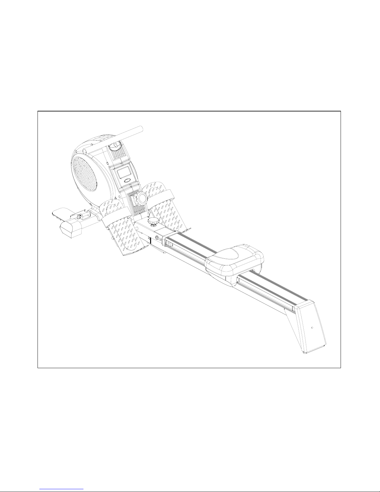
Benefit ER200 II Manual
94102
ROWER MACHINE
Page 2
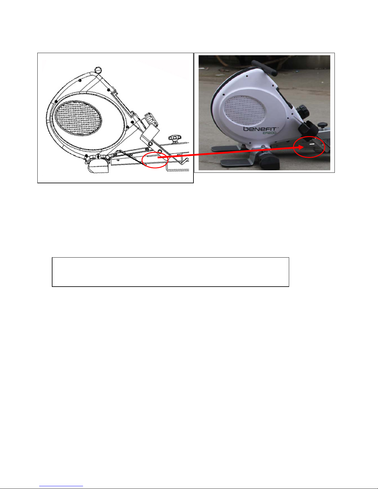
Important: Please locate your serial number and record in the box below for service support
purposes.
Serial number here:
Page 3
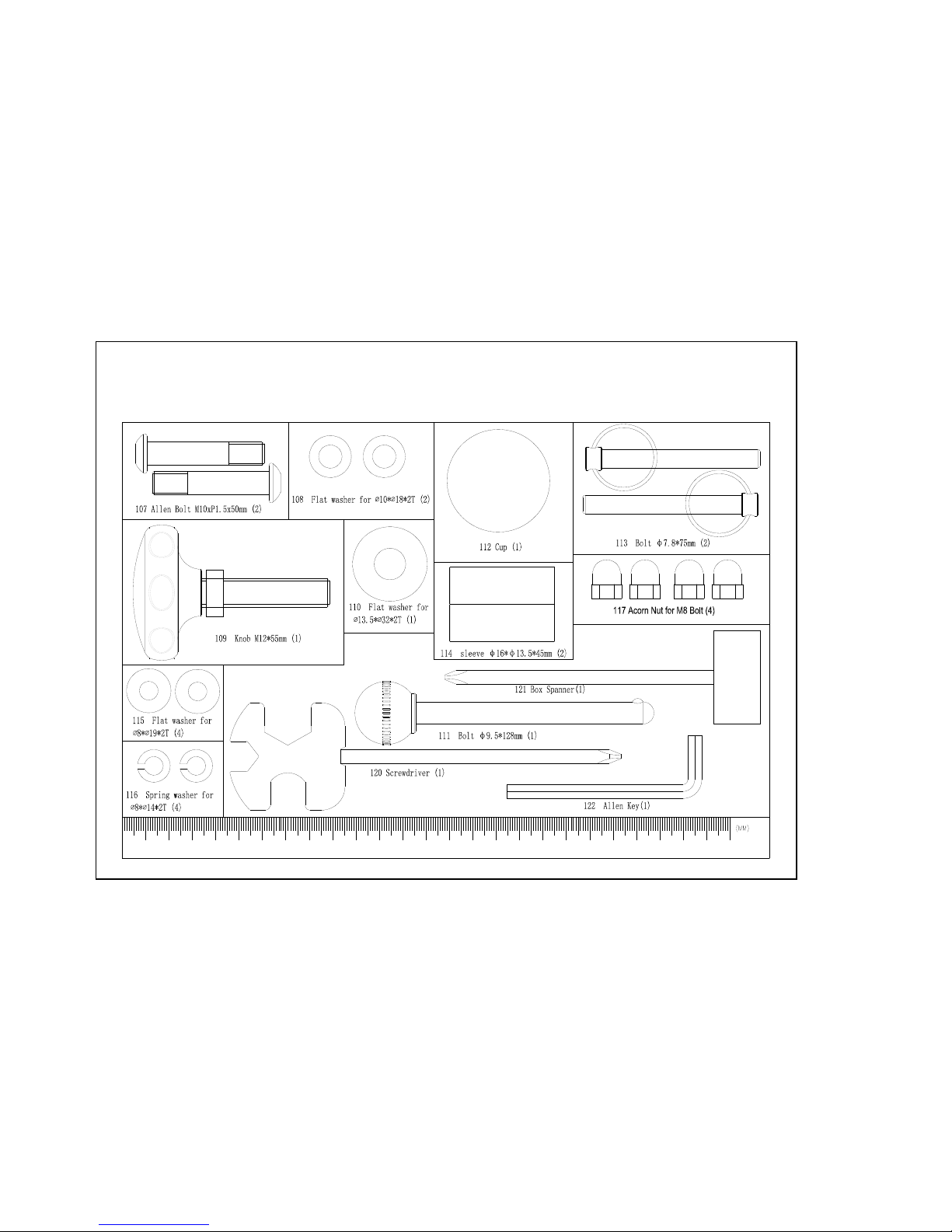
ER200
Page 4
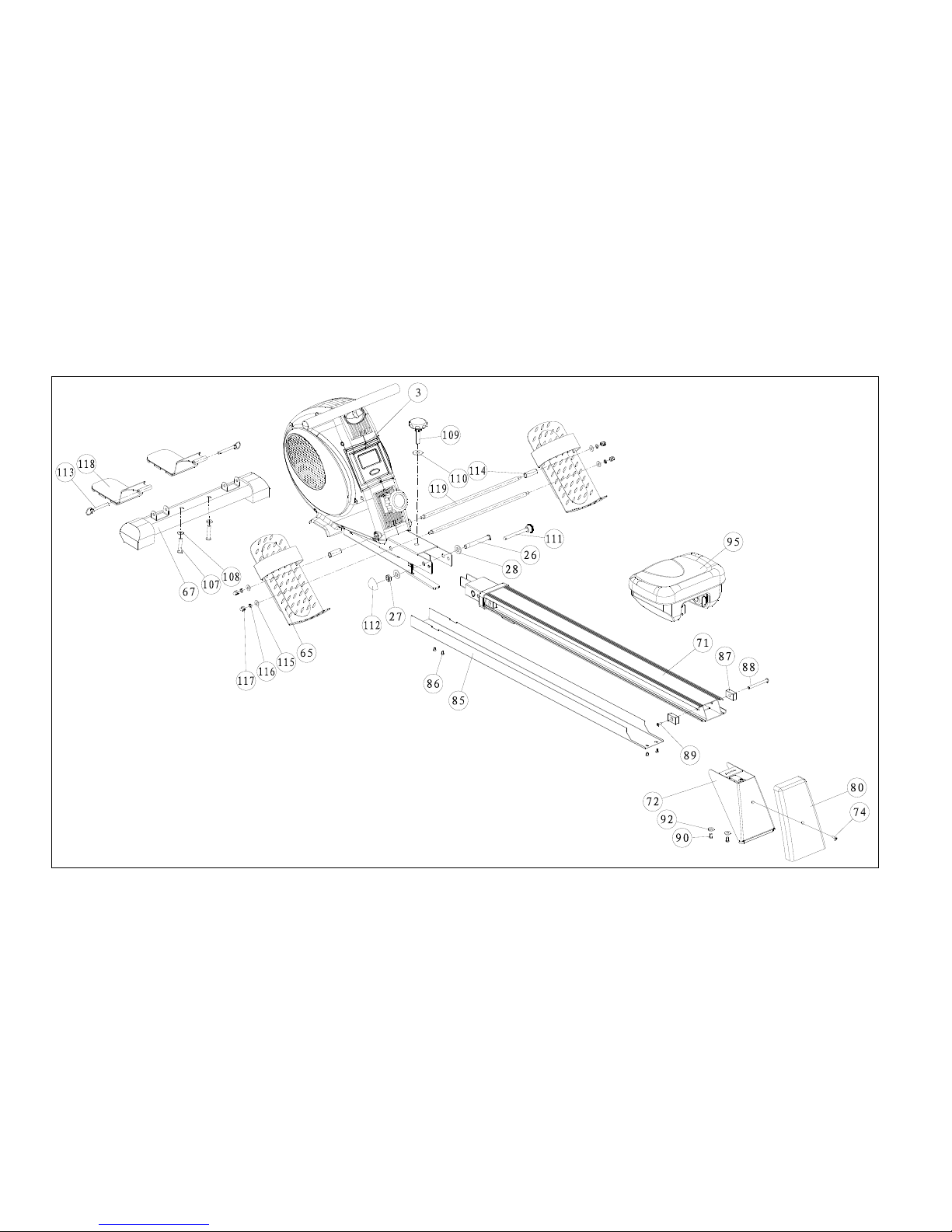
Assembly Diagram
Page 5
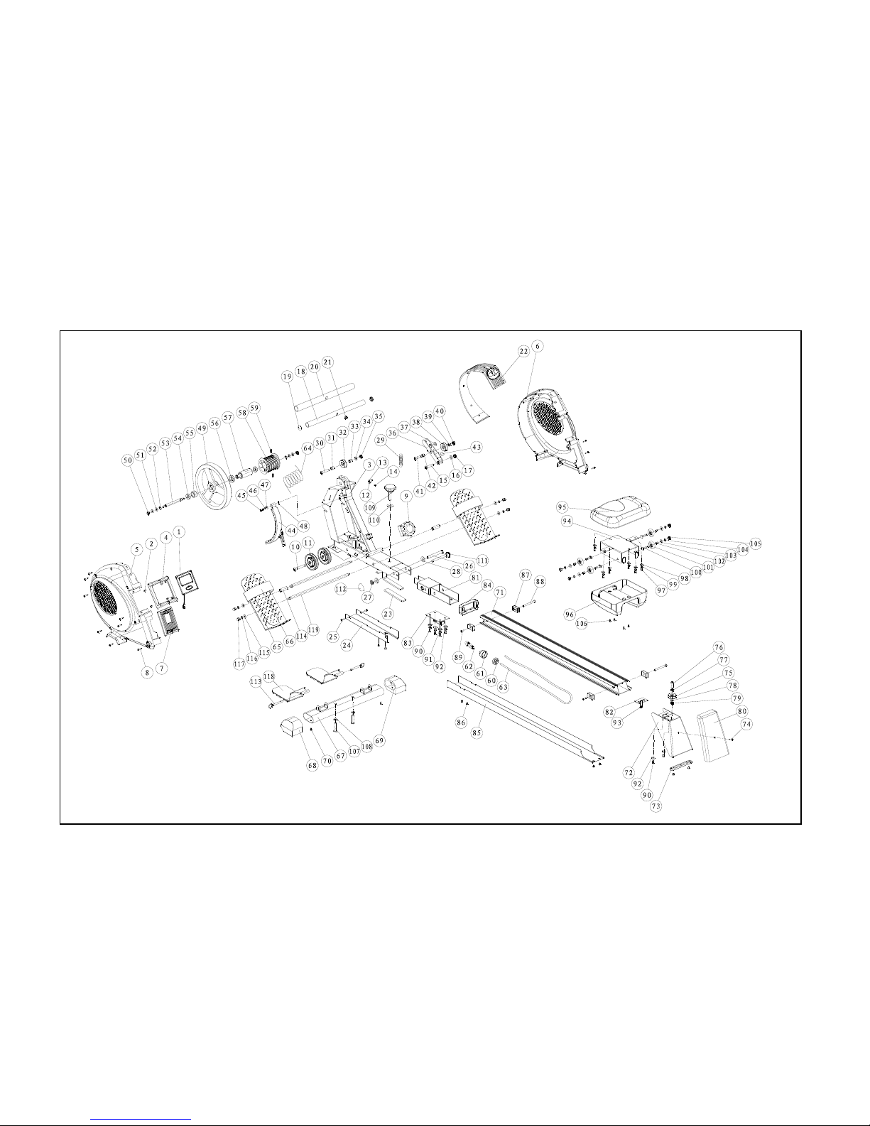
EXPLODED DIAGRAM
Page 6

Parts List
No. Description Q'ty
1 Computer 1 SET
2 M2.5 screw 4 PCS
3
Main body 1
PCS
4 Computer mounting
1
PCS
5 Left-hand housing
1
PCS
6 Right-hand housing
1
PCS
7 Housing cover front
1
PCS
8 M4 screw 11 PCS
9 Resistance controller 1 PCS
10 M10 screw 1 PCS
11 Roller 2 PCS
12 Sensor mounting 1 PCS
13 Sensor 1 PCS
14 M4 screw 1 PCS
15 M10 screw 1 PCS
16 washer 1 PCS
17 M10 nut 1 PCS
18 Tension arm
1
PCS
19 End cap for tension arm
2
PCS
20 Cladding for tension arm
1
PCS
21 Bracket for tension arm
1
PCS
22 Housing cladding for centre section
1
PCS
23 Stationary foot cladding 1 PCS
24 Cover for housing bottom
1
PCS
25 M4 screw
4
PCS
26 Bolt for slide runner
1
PCS
27 Nut M8
1
PCS
28 Washer
2
PCS
29 Spring
1
PCS
30 M10 screw
1
PCS
31 Guide bush
1
PCS
32 Roller 42 mm 1 PCS
33 Guide bush 1 PCS
34 Washer 2 PCS
35 M10 nut
1
PCS
36 Magnet mounting 1 SET
37 Magnet 1 PCS
38 Roller 1 PCS
39 Guide bush 1 PCS
40 M10 nut 1 PCS
41 M10 screw 1 PCS
42 Guide bush 1 PCS
43 Foam 1 PCS
44 Magnet system 1 SET
45 M6 screw 1 PCS
46 Spring washer 1 PCS
47 Washer 1 PCS
48 Wave washer 1 PCS
49 Flywheel 1 PCS
Page 7

50 M8 nut 2 PCS
51 Washer 4 PCS
52 C-type 2 PCS
53 Flywheel axle 1 PCS
54 6001RS bearing 2 PCS
55 Bearing 1 PCS
56 6904 bearing 1 PCS
57 Mounting for cord guide 1 PCS
58 Cord guide 1 PCS
59
M8 screw 2
PCS
60 Mounting for return cord 1 PCS
61 Cladding 1 PCS
62 Heel 1 PCS
63 Return cord 1 PCS
64 Tension cord 1 PCS
65 Pedal (R,L) 2 PCS
66 Safety strap for pedal 2 PCS
67 Front stationary foot 1 SET
68 End cap for front foot (left) 1 PCS
69 End cap for front foot (right) 1 PCS
70 Screw 2 PCS
71 Aluminum slide runner 1 PCS
72 Rear foot 1 PCS
73 Base plate for rear foot 1 PCS
74 M5 screw 3 PCS
75 Roller 42 mm 1 PCS
76 M10 bolt 1 PCS
77 Guide bush 1 PCS
78 Guide bush 1 PCS
79 M10 nut 1 PCS
80 End cover 1 PCS
81 Connector 1 PCS
82 Fixing plate for rear foot 1 PCS
83 Joint plate 1 PCS
84 End cap, roll bar 1 PCS
85 Cladding for slide runner 1 PCS
86 Bolt 4 PCS
87 Stopper 4 PCS
88 Stopper axle 2 PCS
89 Bolt M6*10 2 PCS
90 Bolt M8*20 6 PCS
91
Spring washer 4
PCS
92
Washer 6
PCS
93
Screw 2
PCS
94
Seat mounting 1
PCS
95
Seat 1
PCS
96
Cladding for seat 1
PCS
97
Screw 6
PCS
98
Washer 6
PCS
99
Spring washer 6
PCS
100
M8 bolt 4
PCS
101
Roller 4
PCS
102
Guide bush 4
PCS
Page 8
103
Washer 4
PCS
104
Spring washer 4
PCS
105
M8 nut 4
PCS
106
Screw 4
PCS
107
Bolt 2
PCS
108
Washer 2
PCS
109
Lock knob 1
PCS
110
Washer 1
PCS
111
Locking pin 1
PCS
112
Nut cover 1
PCS
113
Pin for front grips 2
PCS
114
Spacer sleeve for pedal 2
PCS
115
Washer 4
PCS
116
Lock washer M8 4
PCS
117
Nut M8 4
PCS
118
Front grips 2
PCS
119
Pedal crank 2
PCS
Page 9
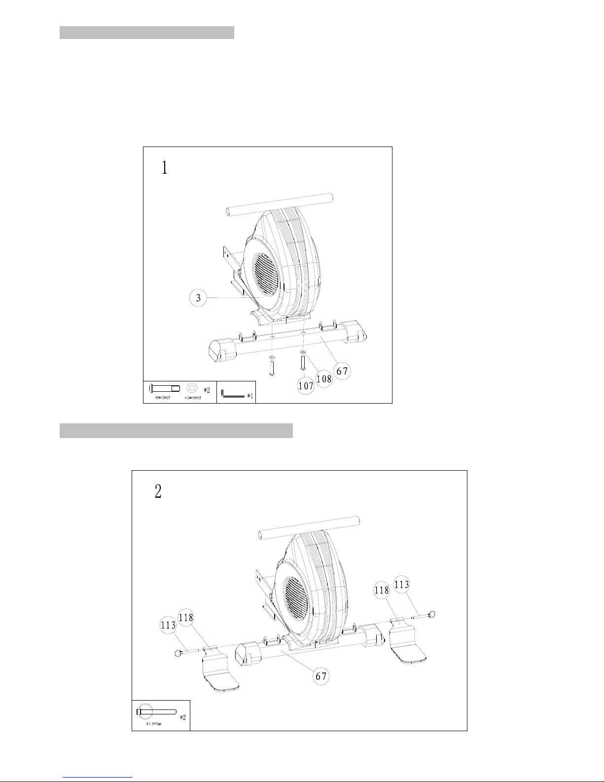
Step 1 Assembly of the front foot
1. Take the front foot (67) with the integrated transport rollers and attach to the main body (3)
using two screws (107) and two washers (108).
Ensure that the transport rollers are facing towards the floor. The tw o elastic end caps for
the stationary foot ensure automatic compensation of any slight unevenness in the floor.
This assembly step requires the assistance of a second person to hold the machine steady.
Step 2 Assembly of the metal tread surfaces
1. Mount the tread surfaces (118) to the front foot (67) using the two locking pins (113).
Page 10
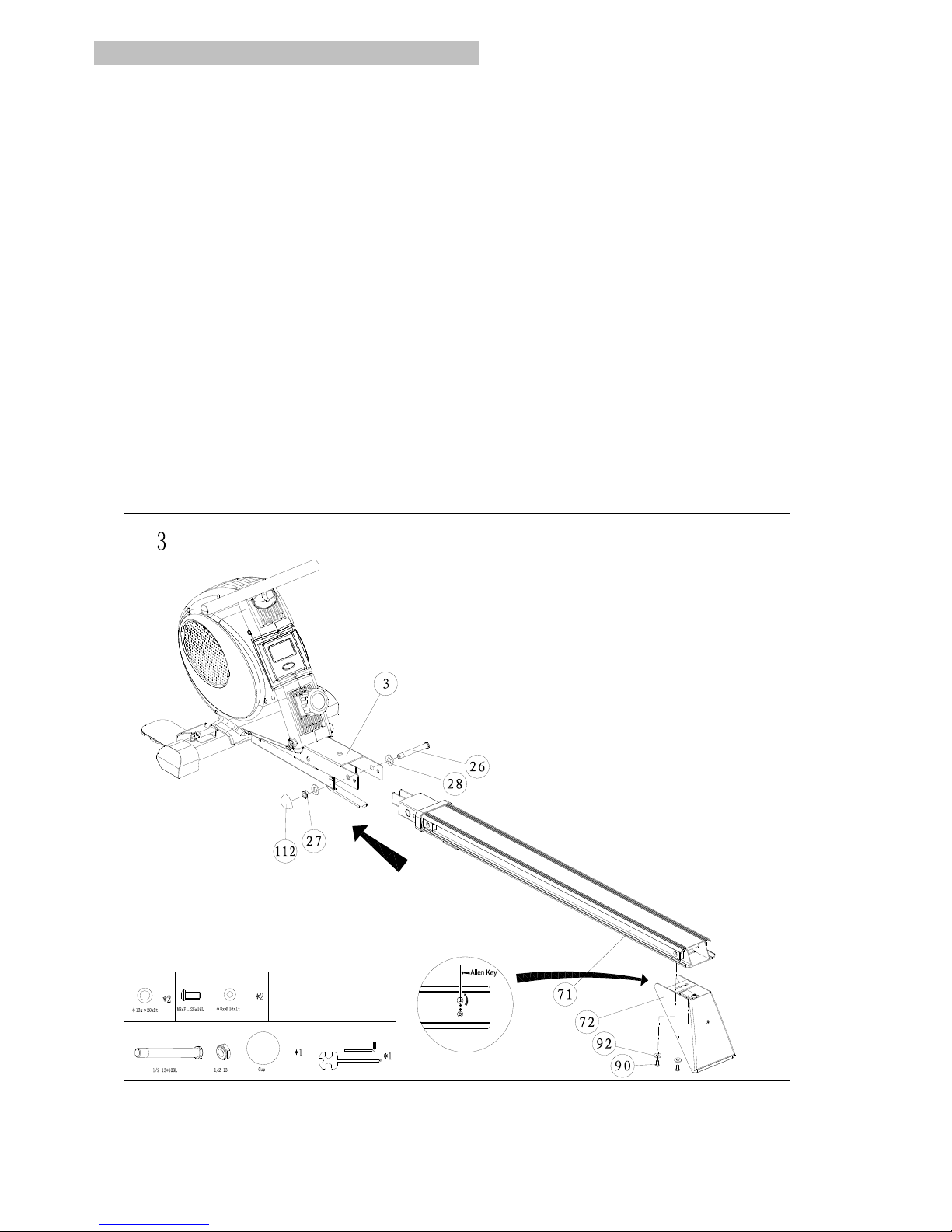
Step 3 Assembly of the aluminum slide runner
1. Prepare the parts of main body (3), aluminum slide runner (71), rear foot (72), locking pin(111)
and nut cover(112).
2. First unscrew the bolts under the aluminum slide runner (71).
3 Assemble the rear foot (72), to the aluminum slide runner (71) with the bolts as shown.
4. Double check the bolts and rear feet are securely installed.
5. Prepare to assemble the aluminum slide runner to the main body.
6. Unscrew the bolt (26), nut (27) and washers (28) for the slide runner.
7. Insert the aluminum slide runner to the main body.
8. Insert the aluminum slide runner (71) and align the conjunction of the hole and fix it with the set
of bolt and washer you’ve just taken.
Make sure the bolts for the aluminum slide runner (71) are securely assembled.
Page 11
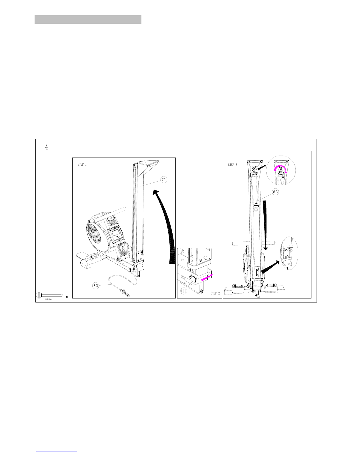
Step 4 Assembly of the return cord
1. Fold up the aluminum slide runner.
2. Insert the locking pin (111) to secure the aluminum slide runner.
3. Loop the return cord (63) around the roller located in the rear foot.
4. Pull the return cord (63) and hook the carabineer to the hole on the aluminum roll bar as shown.
4. Ensure the return cord is parallel.
5. Unscrew the bolt on the aluminum bar at the rear foot and at the bottom.
Page 12
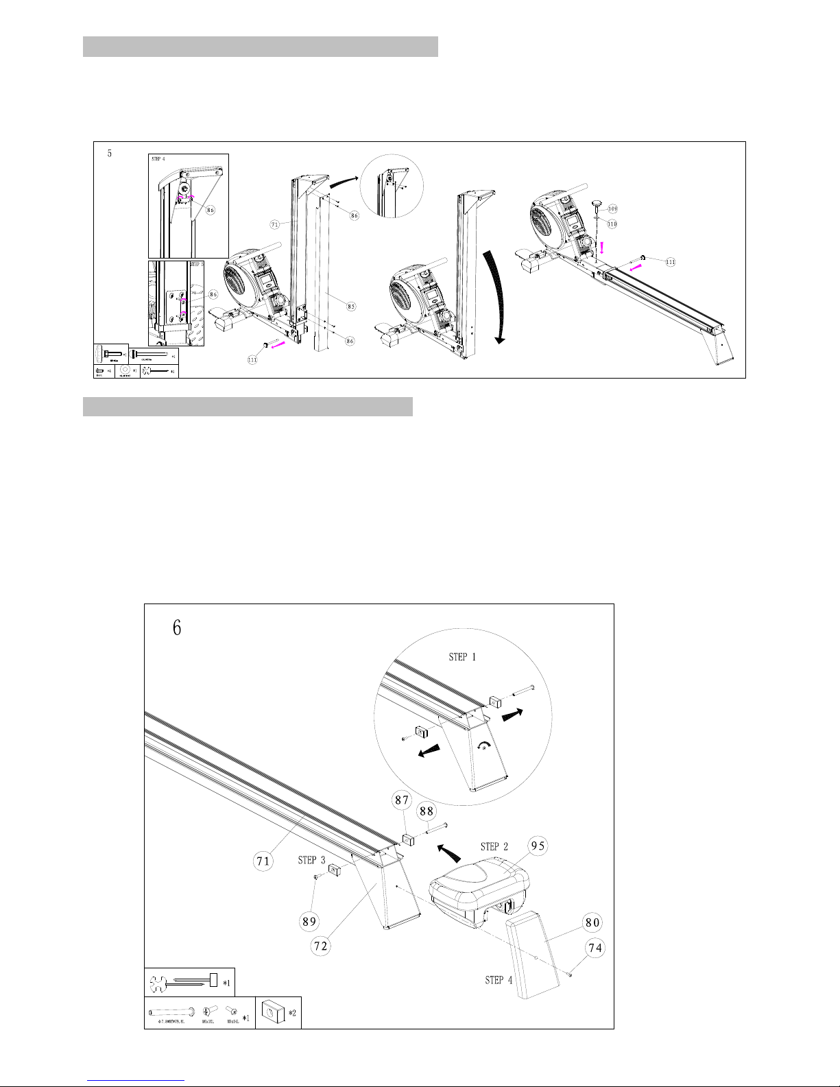
Step 5 Assembly of the cladding for slide runner
1. Take out the locking pin (111) from the main body.
2. Cover the cladding for slide runner (85) to the aluminum slide runner.
3. Secure the cladding for slide runner (85) with 4 bolts accordingly.
4. Fold down the aluminum slide runner.
Step 6 Assembly of the seat and slide runner
1. Unscrew the stoppers on both sides of the aluminum slide runner.
2. Insert the seat (95) to the slide runner, ensure the direction of the seat is facing the
main body.
3. Reinstall both stoppers to the slide runner.
4. Unscrew the bolt at the rear foot, attach the end cover (80) to the rear foot and screw the
Bolt to secure the end cover(80).
5. Insert the locking pin (111).
6. Cover the nut head of the bolt for slide runner (26) using the nut cover (112).
7.. Insert the lock knob(109) with the washer (110) to the hole on the main body as shown.
Page 13
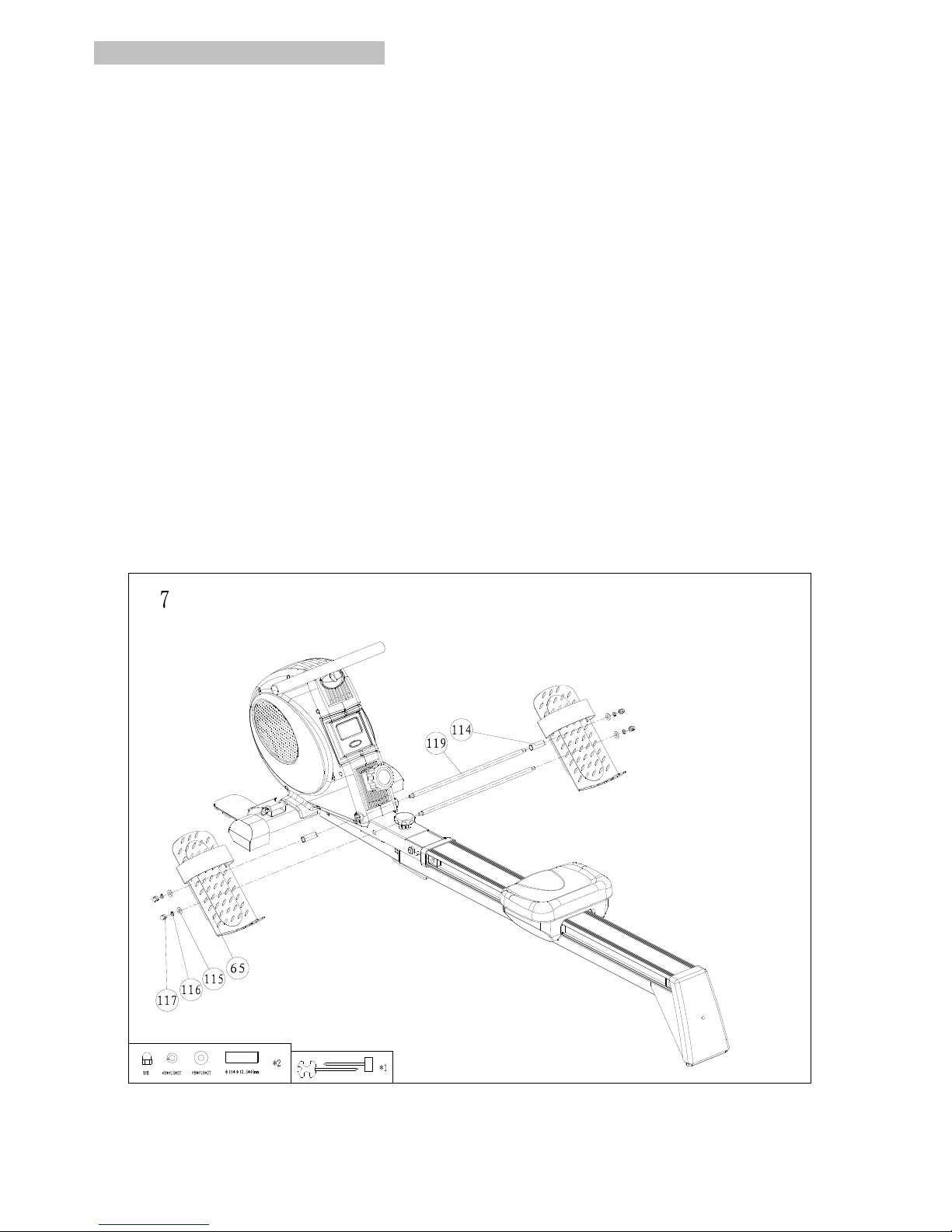
Step 7 Assembly of the foot pedals
1. Prepare the following parts for the pedals assembly step:
-Nut (117) x 4cps
-Lock washer (116) x 4pcs
-Washer (115) x 4pcs
-Right pedal (65) x 1pcs
-Spacer sleeve for pedal (114) x 2pcs
-Top pedal crank (119) x 1pcs
-Left pedal (65) x 1pc
-Bottom pedal crank (119) x 1pcs
-Safety strap for pedal (66) x 2pcs
2. Push the top pedal crank (119) and the bottom pedal crank(119) through the appropriate
openings in the main body as shown.
3. Insert the spacer sleeve for pedal (114) to both ends of the top pedal crank (119).
4. Insert right pedal (65) and left pedal (65), and secure by nut (117), lock washer (116)
and washer (115) accordingly to top and bottom crank.
5. Thread the safety straps (66) to both right and left pedal.
6. Check both straps and the pedal construction stability.
Adjust the safety straps (66) so that they do not cause pressure when rowing but so that a
firm grip on the pedals (65) can be maintained.
Page 14
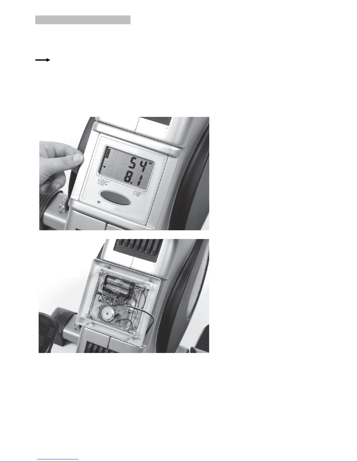
Step 8 - Installing the batteries
Figure A: Push the catch attached to the bottom of the computer slightly upwards and remove the
computer from the holder.
Figure B: Insert 2 x AA 1.5V batteries into the back of the computer.
Reattach the computer by first inserting the top part into the holder and then the bottom part
of the computer until you hear the catch click into position (Figure A).
Remove the batteries from the battery compartment if they are empty or if the equipment is
not to be used for a long period of time.
Batteries are hazardous waste and must be disposed of properly.
A
B
Page 15
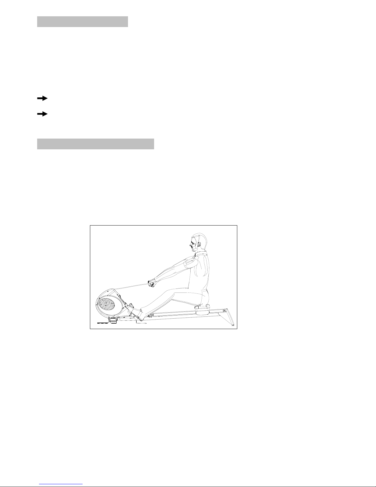
Workout information
WARNNIG!
If you have not exercised for a long time or suffer from heart, circulatory or orthopedic problems,
always consult you doctor before using new exercise equipment
Advise your doctor what equipment you plan to use, the type of exercises and the likely frequency
of exercise to be undertaken.
Maintenance!
Regularly check all equipment parts and mark sure all screws and connections on the seat
are tight.
To avoid any irritating noises, please grease all mobile parts (e.g. bearing bush) from time to
time with a drop of oil.
Correct Rowing Technique
Step 1
※Bring the seat to the front position. For this, bend the hip and knee joints.
※Grasp the rowing handle with both hands form above.
※Make sure you are sitting upright/straight.
※Persons suffering from knee complaints should not bend their knees to an angle less than 90 .
※Slowly start to stretch your legs.
※Pull the rowing handle in your direction. Make sure you are sitting upright/straight.
※Draw your legs up again and roll the seat back into the starting position.
Page 16
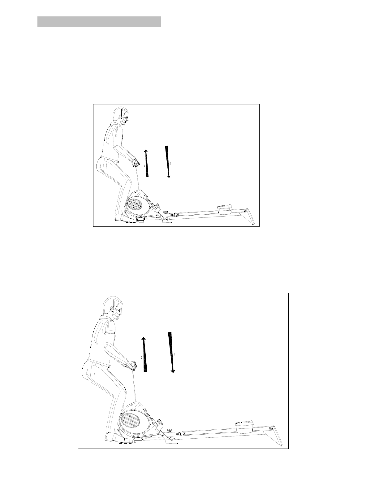
Additional Workout Options
Using the rowing handle, it is also possible to exercise you biceps (exercise 1), your shoulders and
back muscles (exercise 2) :
Exercise 1
※
Position both of your legs on the tread surfaces which are attached to the front foot.
※ Grasp the rowing handle with both hands from above.
※ Pull the rowing handle in your direction by bending your arms in a slightly bowed position.
※ Make sure that your legs are slightly bent.
Exercise 2
※ Position both of your legs on the tread surfaces which are attached to the front foot.
※ Grasp the rowing handle with both hands from below and pull it in your direction until you are
sitting in an upright position and both arms are bent at right angles.
※ Now pull the rowing handle upward by bending your arms.
※ Make sure your back remains upright and straight at all times.
Page 17
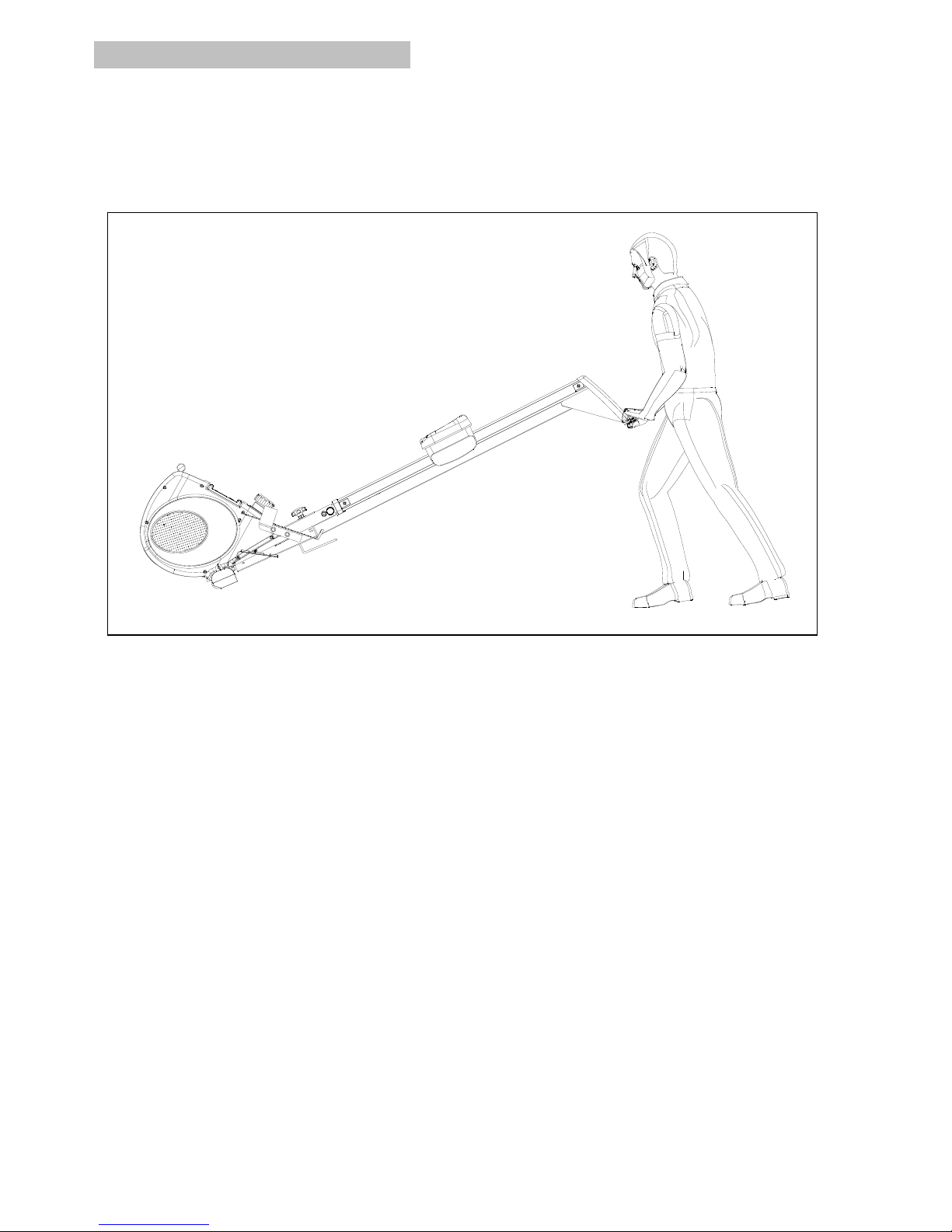
Moving the rowing machine:
Take the rear foot of the rowing machine and tilt the machine forward until it can be pushed easily.
*
Remove the metal treads prior to moving the machine using the transport rollers.
* Never move the machine over steps or other obstacles on your own.
Page 18
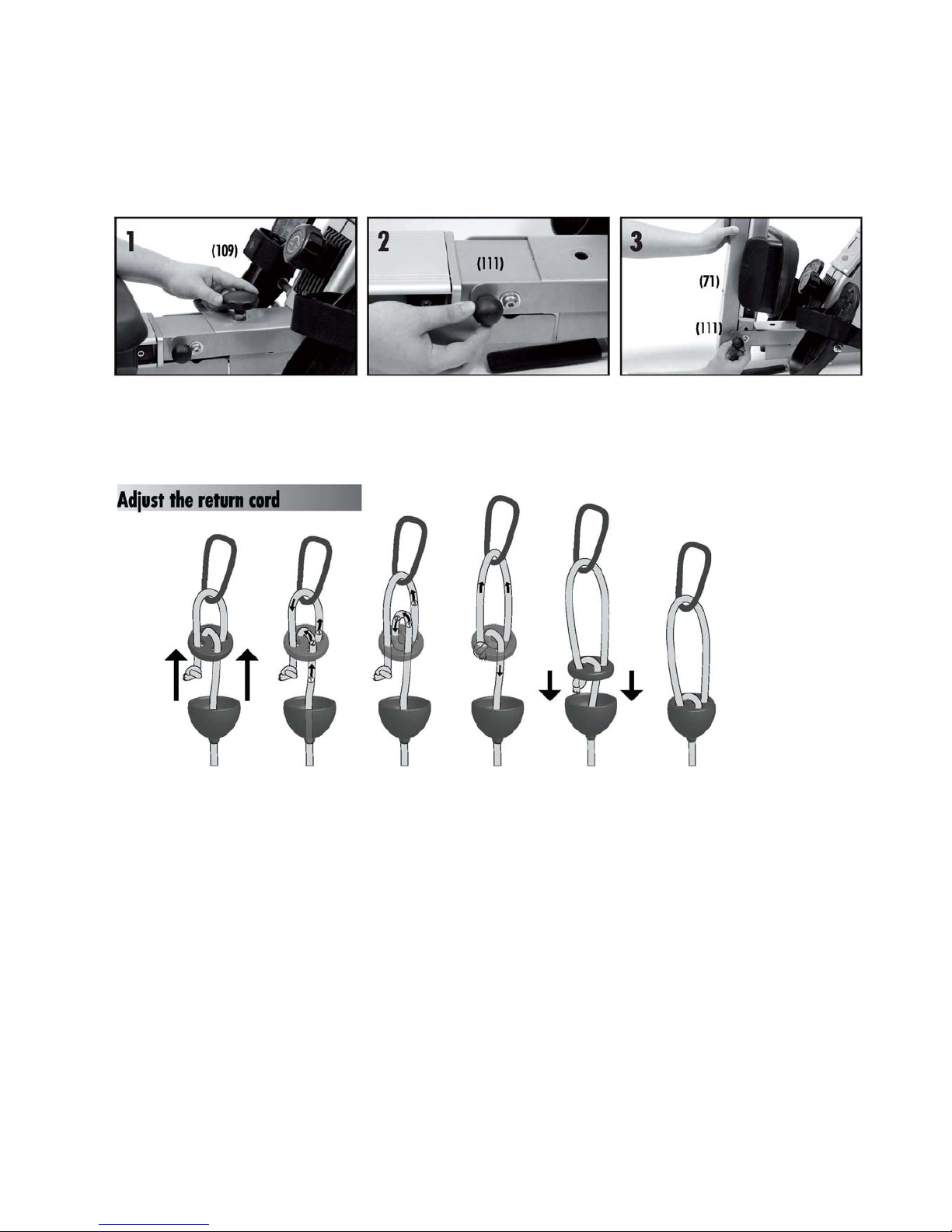
Folding the rowing machine:
1. At first loosen the lock knob (109)
2. Remove the locking pin (111).
3. Fold the slide runner (71) upward and secure the locking pin (111).
When unfolding the machine, proceed in the reverse assembly sequence and always make
sure that you rowing machine in stored safely.
Adjust the return card
To adjust the tension of the return cord, simply adjust the length of the loop as per the above
instruction. The larger loop you have fixed, the more tension you can get.
Page 19
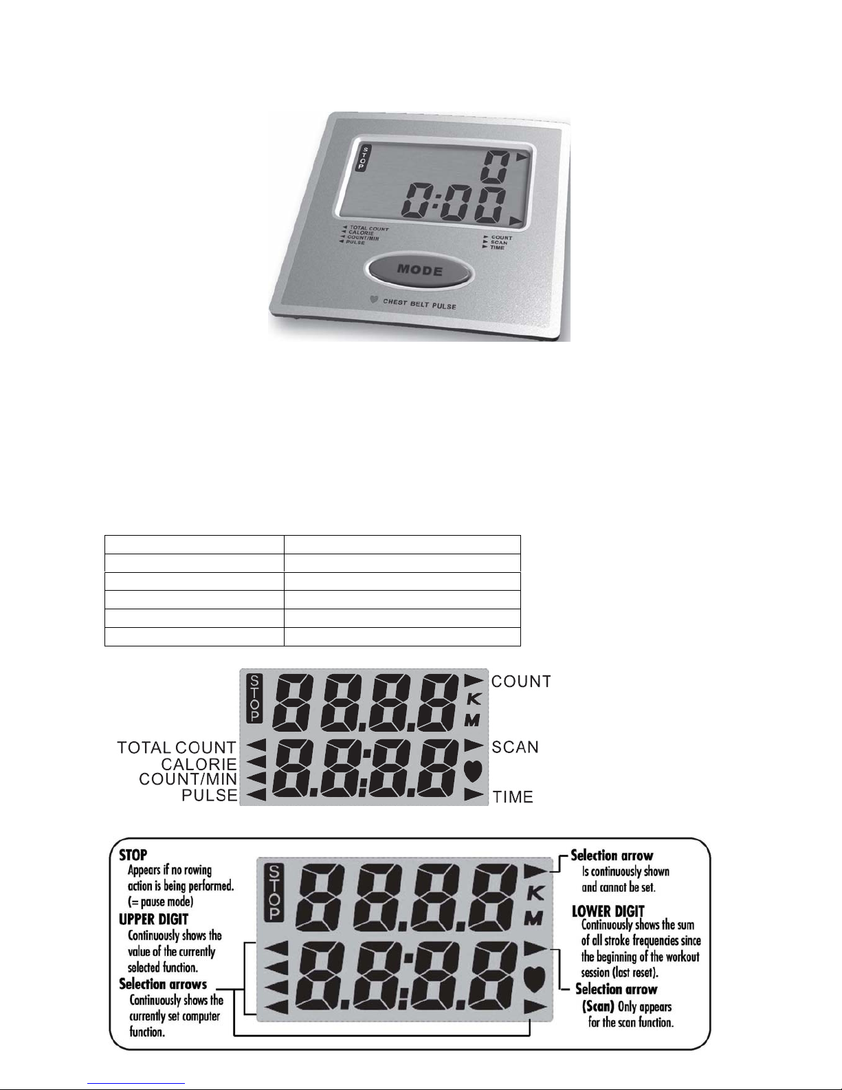
Instruction Manual of ST3663-64
!!! For simple exercise, it is not always necessary to select a function or other values. You can
simply start rowing.
As soon as user install batteries, computer will power on and LCD full display all segments with an
acoustic sound then enter into the SCAN function mode after one second. Press the MODE key to
select function.
When there is rowing signal transmitted to the computer without pressing any key, computer will
starts to work, all function TIME/STROKES/CALORIES/TOTAL STROKES/PULSE will start to
count up automatically.
If no pressing button and rowing movement for 4 minutes, the computer will switch to Idle mode
and LCD will power-off. Press the MODE button or start rowing can wake up the computer.
【DISPLAY & BUTTON FUNCTIONS】
Training Values Display Range
TIME
00:00 ~99:59 min.
STROKES
0~9990
TOTAL STROKES
0~9999
CALORIES
0.0~999.9Cal
PULSE
0-40~240 bpm
Page 20

Training Data
The computer calculates and displays all values automatically according to user training status.
Operation Instruction
Press MODE button to select function to display, the following function will be display in sequence:
SCANÆTIMEÆ STROKESÆ CALORIESÆTOTAL STROKESÆ PULSEÆSCAN.
*SCAN - In SCAN mode, press MODE key to choose other functions display.
Automatically scan through each mode in sequence every 6 seconds.
* TIME – When you start exercising, computer will count up rowing TIME automatically.
No exercising for 4 minutes, STOP icon will shows up.
* STROKES – When you start exercising, computer will count up your strokes automatically.
No exercising for 4 minutes, STOP icon will shows up.
* CALORES – When you start exercising, computer will accumulate calorie consumption
automatically.
* TOTAL STROKES – When you start exercising, computer will accumulate your Total strokes
automatically.
* PULSE - The computer will display your Heart rate while exercising. When you start
exercising, you have to wear the chest belt to transmit HR to computer. After 6-7
seconds, the PULSE figure will display. If you wear the belt improperly, the Pulse
figure will become unstable. W/O pulse signal input for 6 seconds, computer will
displays “P”.
Take Note:
* When stop training for 4 minutes, the main screen will be off.
* STOP SIGNAL-STOP signal will light up when SCAN function is under executing.
* When the display of LCD is weak, it means the batteries need to be changed.
* If there is no signal when you exercise, please check if the cable is well connected.
* If the computer displays abnormally, please re-install the batteries and try again.
BUTTON FUNCTION
MODE
-Select function
-Clear all values and reboot computer if hold on for 3 seconds
 Loading...