


Digital Multifunction Sound Unit
TBS Mini
*** FREE OF CHARGE sound libraries available at www.benedini.de ***
Content
1. Features
2. Connections
2.1. Installation schematic
3. Control modes
3.1. Controlling the sound unit by the 12-positon “encoder” (12-Key coder)
3.1.1 Push button encoder circuit
3.1.2. Teaching the Sound unit for Encoder Control
3.2. Direct Sound Selection
3.2.1. Direct Sound Selection using the Prop2 input
3.2.2. Direct Sound Selection using the Prop3 input
3.3. Indirect Sound Selection “2-Key Coder”
3.3.1. Teaching the sound unit for “2-key Coder” control
3.4. Autostart
4. Changing the control mode
5. Configuration of the sound unit by the optional USB programming cable and a PC
6. Technical data
The Control Mode set on this Sound unit on delivery:
O Encoder (Prop3) O Direct Sound Selection (Prop2)
O Indirect Sound Selection (Prop3) O Autostart
Loaded sound set: ________________________
Flashing output: O None O Out1 O Out2
TBS Mini www.benedini.de Page 1 of 11

1. Features
The TBS Mini is developed for all kind of RC models, including airplanes, tanks, trucks,
crawlers...
It is an enhanced version of the proven TBS Micro Sound unit.
•
Fully customer programmable. Your own sounds can be loaded!
•
Large sound library of original recordings available. Please check www.benedini.de
•
Sound quality 8 / 11 / 16 / 22KHz
•
Capability to play two sounds simultaneously (engine and one special sound)
•
2 Mbyte of sound memory, enough for 93sec. at 22KHz
•
Internal amplifier with 1.2W if using an 8 Ohm speaker.
•
External high power amplifiers available
(f.e. 2x40W at 2Ohm and 12V supply OR 50W at 8 Ohm and 50V supply)
•
Up to 6 switching outputs.
- Triggerable by sound (eg Muzzle flashing) or independently (universal switching unit)
- Switching - momentary - or flashing mode adjustable
•
Two servo signal outputs (eg For retractable landing gear)
•
Only one proportional channel necessary to control all functions of the unit.
•
The speed signal is taken from the receiver. This allows combination with brushless or
brushed motors.
•
Horizontal plug connections. This allows total electric isolation by heat shrink tube.
•
Very small dimensions and weight
•
USB or RS232 programming cable available (optional)
•
Totally programmable by the free of charge software “TBS Flash”:
- You can load your own sounds or any of the Benedini sounds available at www.benedini.de
- Firmware update! This means you have always the latest software at you unit.
- FREE OF CHARGE sound libraries available at www.benedini.de
The TBS Mini sound unit can be fully configured by the optional USB programming cable and a
PC. Please see the separate programming manual.
The unit can be controlled by a spare proportional channel which uses an input device to drive it
such as listed below. Eg Most programmable TX’s have one 3Pos switch already installed.
You can purchase, or make, a rotary encoder or push button panel, and it is also possible for you
to replace a rarely used Pot input on the TX with another 3Pos switch for sound unit use.
•
12-position encoder (combination of rotary switch and push button)
for Direct Sound Selection
•
3Pos switch for Direct Sound Selection (2 methods)
•
3Pos switch for Indirect Sound Selection
•
Autostart (without any additional proportional channel for control)
The desired control mode can be set by using the USB programming cable with a PC, or
manually on the Sound Unit (without PC).
TBS Mini www.benedini.de Page 2 of 11

Top
2. Connection
1+2
3+4
Plugs (from top to bottom)
1. 8 Ohm speaker or ext. amplifier
2. Prop1 Input (RX IN)
3. Prop1 Output (ESC OUT)
4. Prop2 Input (RX)
5. Prop3 Input (RX)
6. PWM1 (Servosignal 1) or Out 10
7. PWM2 (Servosignal 2) or Out 11
8. Out 1+2 switching output
9. Out 3+4 switching output
Attention:
All plugs must be connected with the orange or white signal lead on TOP and the
negative supply lead (brown or black) at BOTTOM !!!!
Learn Button
Prog. Cable
Speaker
/ Ampl.
Speaker
Plus
Speaker
Minus
Ground Ground Ground Ground Ground Ground Ground
PROP 1
In
Signal
(Input)
Power Power Power Power Power Power Power Power
PROP 1
Out
Signal
(Output)
PROP 2
In
Signal
(Input)
PROP 3
In
Signal
(Input)
PWM 1
(OUT10)
Signal
(Output)
PWM 2
(OUT 11)
Signal
(Output)
: Signal (orange)
Center: Power (red)
Bottom: GND (black)
OUT
(neg.
switch-
ing)
OUT 1
(negative)
Out 2
(negative)
switch-
(negative)
(negative)
OUT
(neg.
ing)
OUT 3
OUT 4
Speaker connection:
If a speaker is connected directly to the TBS Mini, make sure to use the Speaker Plus and Speaker
Minus pins (upper two pins). You must NOT use the Ground pin at the speaker connector!
Use only an 8 Ohm speaker.
Switching outputs (Out 1..4, Out10, Out11)
All outputs are switching to NEGATIVE of the receiver supply voltage. Positive is available at the
centre pins of the according plugs.
Out 10 is available at the PWM1 plug
Out 11 is available at the PWM2 plug
TBS Mini www.benedini.de Page 3 of 11

Battery
(optional)
Control
2.1. Installation Schematic
Also see the last page !
Verstärker
Amplifier
(optional)
Programming using a PC
Programmierung über PC
(sounds and parameters)
(Sound und Parameter)
Akku
Regler (BEC)
Gas
Throttle
Option
Control
Kodierer
Transistor switched outputs
Schaltausgänge
-
-
+
OUT 1
OUT 2
+
-
+
OUT 3
OUT 4
-
+
Evtl. Vorwiderstand für
LEDs
All switching outputs (Out1-6) can be configured to different modes (switching, latching, flashing)
and can be routed to different sounds for simultaneous action. Most common is using them for gun
muzzle flashing. High power LEDs, including pre-wired cable sets, are available.
TBS Mini www.benedini.de Page 4 of 11
3. Control modes
BOTH
Total resistance
There are several control modes possible, using various TX switch functions and the appropriate
Prop’X’ control inputs, with the TBS Mini Sound Unit also set to interpret the signals correctly.
- Encoder. Using a 12 position encoder, or multi-switch panel.
- Direct Sound Selection. This has two methods possible.
One uses a 3Pos TX switch signal into Prop2 allowing just two of the additional sounds to
be played.
One uses a 3Pos TX switch signal into Prop3 and allows all additional sounds to be played.
- Indirect Sound Selection
- Autostart. This mode only uses the Throttle signal to control startup, running, and shutdown
of the engine sound only. No additional sounds can be controlled or played.
The supplied control mode that was set in the Sound Unit at delivery is indicated on the first page of
this manual.
Please refer to the appropriate section below on how to teach the sound unit your control method.
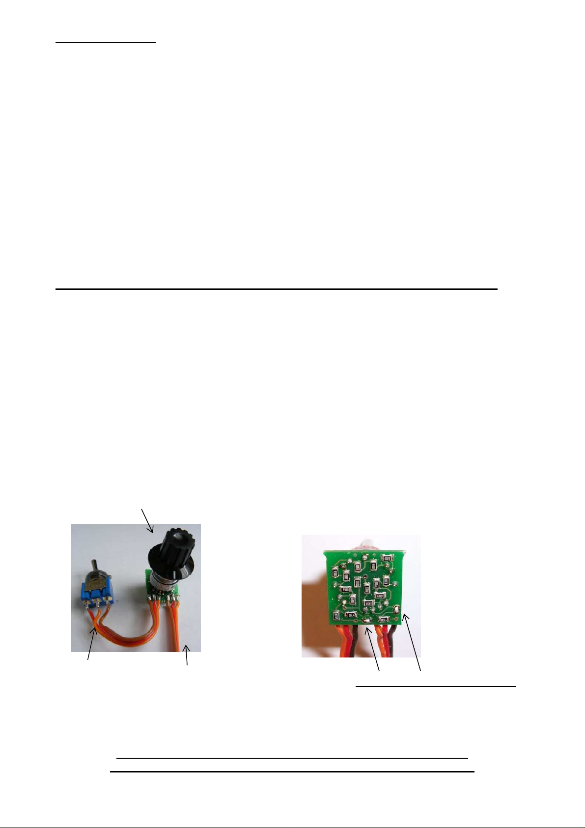
3.1. Controlling the sound unit by the 12-positon “encoder” (12-Key coder)
The most comfortable way of controlling the sound unit is using the so called “12-position
encoder”. It consists of a 12 position rotary switch in combination with a push button. The desired
sound is selected by the rotary switch position and is then triggered by the push button.
The encoder is connected into your transmitter to a spare proportional channel. This TX mod must
be done by yourself. The rotary switch is optional and must be ordered separately!
After installation you should test the encoder by using a servo on the appropriate receiver channel
you intend to use. Keep the encoder push button pressed and move the rotary switch through all
positions. The servo should move to a new position at each rotary switch position. The total
movement of the servo should be about the same as at a normal joystick channels set to 100%
travel.
Rotary switch for sound selection
The total resistance of the encoder can be adjusted
to your TX by two solder bridges at the rear side
of the encoder pcb:
Trigger switch
TBS Mini www.benedini.de Page 5 of 11
Connect to a spare
proportional Channel
of your TX.
bridges open approx. 22 KOhm
closed approx. 5 KOhm
The installation of the encoder in your transmitter is on your own risk
Proper functionality is not guaranteed at ALL transmitter brands / types

3.1.1. Push button encoder circuit
A simple resistor array combined with some push buttons can be also used to control the sound
unit. This is only a suggestion and needs to be built by yourself:
P1
CW
5k
R1
390
S1 S2 S3 S4 S5 S6 S7 S8 S12S9 S10 S11
R12
5k6
R2
390
R3
390
R4
390
R5
390
R6
820
312
ST1
Zum Sender
R7
390
R8
390
R9
390
R10
390
R11
390
R13
5k6
P2
5k
You should check the operation of the control panel by controlling a servo. Each switch further
along the line will move the servo to another position further from the last switch.
Adjust the min. and max. travel range with the potentiometers P1 and P2 to get a full range as
per a normal TX proportional channel does.
The installation of this circuit in your transmitter is on your own risk
Proper functionality is not guaranteed at ALL transmitter brands / types
3.1.2. Teaching the sound unit for encoder control
1) Power on the transmitter and receiver. The sound unit LED blinks fast = normal mode
Bring all joysticks to neutral position and the throttle to minimum.
2) Press the LEARN button until one beep occurs. The LED is continuously lit.
At this step all neutral / idle positions are stored.
3) Move the throttle stick to your desired acceleration point (the throttle stick position where
engine idle sound changes to the moving sound) and push the button of the encoder.
A short sequence of the acceleration sound file is played
4) Move throttle stick to full throttle and push the encoder button again
A short sequence of the full speed sound file is played.
5) Bring the encoder rotary switch to its first position and push the encoder button
Triggering the engine Start/Stop is stored to this switch position.
The rotary switch has no mechanical limits. You can define any position as the “first”
one.
6) Move the encoder rotary switch to the next position, wait about 2 seconds, and then push the
encoder button again.
Triggering Revving up the engine is stored to this switch position
7) Repeat step 6 until all 12 rotary switch positions are stored.
8) After teaching all positions the sound unit will beep 3 times and will revert back into normal
operation mode.
If you are using the switch/resistor network shown above instead of the encoder, each rotary switch
position is represented by one of the push buttons.
CW
TBS Mini www.benedini.de Page 6 of 11

3.2. Direct Sound Selection
For this control mode you need a proportional channel equipped with a 3 position switch. It is
possible for you to replace a rarely used Pot input on the TX with another 3pos switch for sound
unit use. There are two Direct Sound Selection modes you can use (see below).
The output of the RX channel you assign this input to needs to move from -100, to 0, to +100 for
the three positions.
3.2.1. Direct Sound Selection using the Prop2 input
You do not need to ‘teach’ the Sound unit anything for this mode. The 3pos switch RX channel
must be connected to Prop2 input of the TBS Mini Prop2 input. The mode set for Prop2 in the TBS
Mini must be set to “Function ½” by the TBS Flash software. The two switch positions will play:
1) The engine Start or Shutdown sound (toggles) and 2) The first sound file in the Additional
Sounds list.
These settings are already done if this control mode was ordered with Direct Sound Selection.
The two triggered sounds are set in the TBS Mini flash memory (as set by the TBS Flash) and
others cannot be selected. They can be changed by reprogramming the TBS Mini using the optional
USB programming cable with a PC.
3.2.2. Direct Sound Selection using the Prop3 input
The advantage of this Direct Sound Selection mode is that you can choose/program the desired
Additional Sound by ‘teaching’ the TBS Mini Sound unit which one you want to use.
The 3pos switch RX channel must be connected to the Prop3 input of the TBS Mini. The mode set
for Prop2 in the TBS Mini must be set to “12 position encoder by using the TBS Flash software.
The two switch positions will play: 1) The engine Start or Shutdown sound (toggles) and 2) The
Sound File you ‘teach it’ from the Additional Sounds list in the TBS Mini.
1) Power on the transmitter and receiver. The sound unit LED blinks fast = normal mode.
Bring all joysticks to neutral position and the throttle stick to minimum.
2) Press the LEARN button until one beep occurs = the LED is continuously lit.
At this step all neutral / idle positions are stored.
3) Move the throttle stick to your desired acceleration point (the position where you want the
engine idle sound to change to the moving sound) and flick the 3way switch UP.
A short sequence of the acceleration sound file is played.
4) Move throttle stick to full throttle and flick the 3way switch UP again.
A short sequence of the full speed sound file is played.
5) Flick the switch UP.
The Engine start/stop Sound File is stored to this direction of the switch.
6) If you want to skip the next sound file in the list, flick the switch UP again.
A section of that sound is played but NOT stored to this direction of the switch, because it is
already occupied by the above Engine Start/Stop function.
7) Repeat step 6 to skip any further sound you do not want to select.
8) At your desired sound is next then flick the switch DOWN.
9) Power the sound unit off and on.
Now you can activate the two selected sounds directly by the two non-centre switch positions.
You may need to run this teaching sequence several times because you probably don't know which
sound appears next in the sound list until you have tried it.
TBS Mini www.benedini.de Page 7 of 11

3.3. Indirect Sound Selection mode - “2-Key Coder”
This mode can utilise a 3pos switch as an ‘encoder’ so that you can select ANY of the Additional
Sound Files to play.
The 3pos switch RX channel must be connected to Prop3 input of the TBS Mini. The mode set for
Prop3 in the TBS Mini must be set to “1st Coder 2 Key” by using the TBS Flash software.
Selecting a Sound:
The desired sound (eg sound #3) is selected by toggling the switch 3 times from its center position
in one direction. This tells it to select Sound File #3. Now the selected sound is triggered by pushing
the switch to the other direction. The last selected sound can be triggered multiple times, without
new selection.
1: Selection of sound / action (1-12)
2: Triggering of selected sound / action
3.3.1. Teaching the sound unit for “2-Key Coder” control
‘Teaching’ of this mode is only to set the throttle trigger positions.
1) Power on the transmitter and receiver. The sound unit LED blinks fast = normal mode.
Bring all joysticks to neutral position and the throttle stick to minimum.
2) Press the LEARN button until one beep occurs = the LED is continuously lit.
At this step all neutral / idle positions are stored.
3) Move the throttle stick to your desired acceleration point (the position where you want the
engine idle sound to change to the moving sound) and flick the 3way switch UP.
A short sequence of the acceleration sound file is played.
4) Move throttle stick to full throttle and flick the 3way switch UP again.
A short sequence of the full speed sound file is played.
TBS Mini www.benedini.de Page 8 of 11

3.4. Autostart
TBS Mini speaker plug
If you are interested only in an engine sound the “autostart” mode can be used. The engine starts
automatically at the first short acceleration.
If the engine is more than 20s idle, it shuts down automatically.
There is no extra control channel necessary.
No special sounds can be played in this mode and NO switching outputs can be used !!!!
Teaching the autostart mode:
NOTE: During the programing sequence:
After you move the throttle stick from the last stored position a very short beep is played. You
have about 2 seconds to move to the new throttle stick position to be stored next.
1) Power on the transmitter and receiver. The sound unit LED blinks fast = normal mode.
Bring the throttle stick to minimum.
2) Press the LEARN button until one beep occurs = the LED is continuously lit.
At this step all neutral / idle positions are stored.
3) Move the throttle stick to your desired acceleration point and wait for a Beep.
4) Move throttle stick to full throttle and wait for three Beeps.
The Sound unit will revert to operational mode after a short time.
4. Changing the control mode
It is possible to change the set control mode without the optional USB programing cable:
1. Press the programing button DURING powering on the sound unit.
2. Release the button.
3. Press the prog. button momentarily and you will hear a “Beep-Code”.
4. Repeat pressing the button until the desired control mode is signalized by the according
“Beep-Code”.
5. Switch the sound module off and on again.
„Beep-Code“
1 x Beep -> Autostart
2 x Beep -> Toggle switch
3 x Beep -> 12 position encoder
Note:
If the control mode “autostart” is selected, there is no control channel defined.
If you want to switch from autostart to another control mode you need to program a control
channel by using TBflash and the optional programming cable!
5. Connecting an external amplifier
If you want to connect an external amplifier, other than a Benedini one, please follow this
schematic: Watch the ground connection !!!!
Spkr Plus
Spkr Minus
Gnd
Volume Pot: 220 Ohm
Throttle
Audio to the
Amplifier
TBS Mini www.benedini.de Page 9 of 11

6. Configuration of the TBSmini Sound unit using the optional USB
programming cable and a PC
Please see the separate manual for the configuration software called “TBS Flash”.
The manual as well as the software is available free of charge at www.benedini.de.
Note:
The sound unit needs to be powered from the receiver power while being used with a PC. It is NOT
powered by the USB cable!
7. Technical data
Supply range: 3.5V – 12V (from receiver)
Internal amplifier: 1.2W at 8 Ohm with a 5V supply
Switching outputs: Negative switching - Max. 12V / 0.5A each
Dimensions: 55 x 25 x 10mm
Weight: about 6g
You should do a range check of your remote control after installation and ensure a proper
working RC system under all conditions !
Disclaimer
a.) www.benedini.de provides the equipment solely to be used by each purchaser in
accordance with the specific instructions supplied with each Sound Module and that the
purchaser undertakes that the Sound Module and any associated equipment e.g. Amplifier,
Speakers, etc. will be operated within the parameters contained therein.
b.) www.benedini.de accepts no liability for any damage to any Sound Module if it is
determined that the damage has been caused by either non adherence to the instructions or due
to any malfunction by any cause or reason whatsoever within the model or its equipment and
thereby outside of the control of www.benedini.de.
c.) www.benedini.de supplies each Sound Module on the strict undertaking that it will be
used in such a manner to comply with the laws of the purchaser’s country of residence.
d.) www.benedini.de has no control over the final assembly, no liability shall be assumed nor
accepted for any damage resulting from any use by user of the final assembled product, the user
accepts all resulting liability.
Technical changes reserved Not suitable for children under 14 years
Benedini Modellbauelektronik
Müllergasse 15, 52159 Roetgen, Germany
Web: www.benedini.de
Mail: Thomas@Benedini.de
TBS Mini www.benedini.de Page 10 of 11

Standardwiring of TBS Mini in “Autostart” control mode, together with 2x40W amplifier
TBS Mini www.benedini.de Page 11 of 11
 Loading...