

Page 1
Remote entry system
SYSTEM INSTALLATION
Remove the plastic covers the dashboard of the vehicle. Find the wires that control central locking,
located on the control unit. For some types of vehicles to be powered directly by the central locking the
door of the car. The testing functions in the vehicle wiring, use only digital multimeter, and even if you
know what function the wire serves.
After determining the wires, disconnect the battery and connect the wiring harness designed for central
locking wires for proper functioning, according to the attached diagrams. All connections soldered
and insulated. After installing central locking plug from the car battery and insert the fuse into the fuse
housing from the central locking.
Protest the proper functioning of the central locking and electric vehicles performance (ignition,
directional lights, ..) Install the plastic covers of the dashboard.
The location of the control unit
Place the control unit from inside the protective plastic dashboard. Attach the antenna control unit so
that it does not touch the metal parts of the vehicle.
SYSTEM DESCRIPTION
Module BENE 102A, it is upgrade of central door locks. The BENE 102A allows locking and unlocking
car by remote controller, with signalization of indicators. Also allows trunk open.
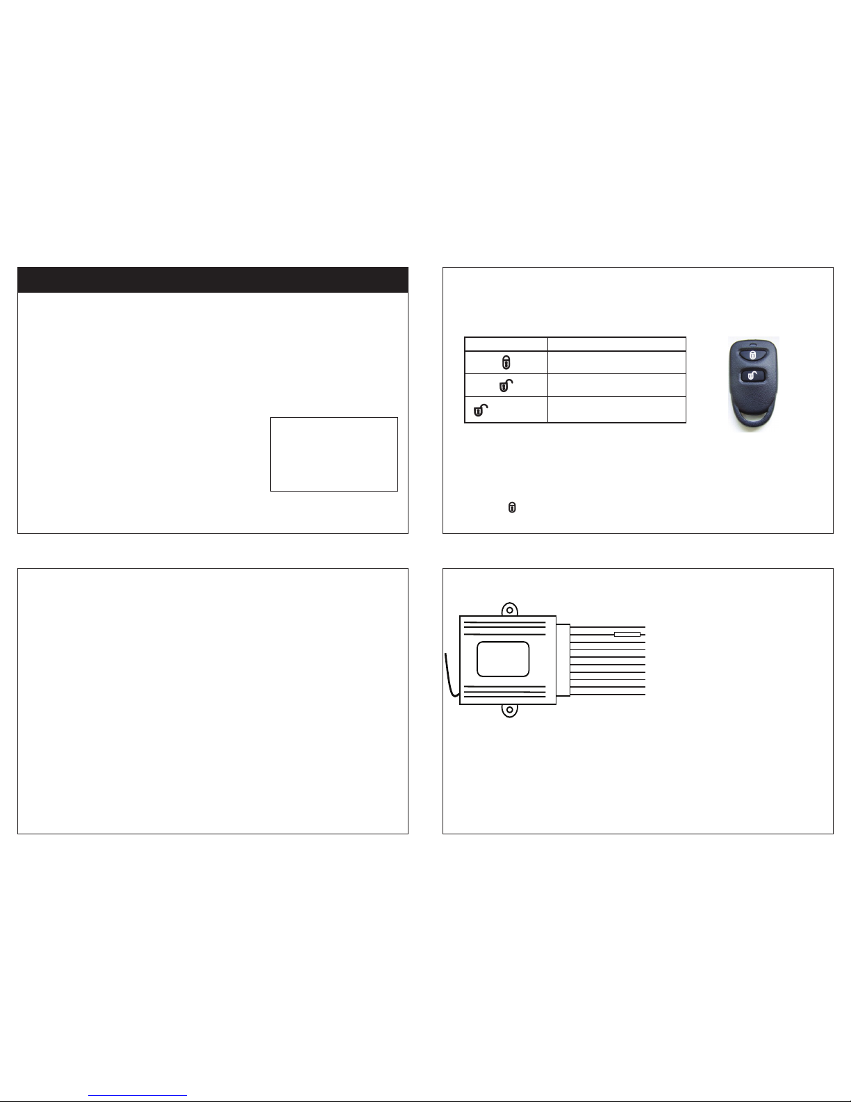
REMOTE CONTROL BUTTON DESCRIPTION
PROGRAMMING THE REMOTE CONTROLS
Up to 4 remote controls can be programmed into system. Each remote must repeat the entire
procedure. Two remotes supplied in the box are already programmed.
Procedure:
1. Open system unit cover and connect jumper on board for 2 seconds. Unit enters into code learning
status, lights start ashing and central locking will lock.
2. Press button and hold it till car‘s lights turn off.
KEYLESS ENTRY SYSTEM DIAGRAM
NOTE:
1. If is Green wire ( input to relay ) connected to +12V, than Yellow wire (relay output to trunk) will has
+12V for two seconds, when is function open trunk activated. In case, that Green wire is connected to
GROUND, than Yellow wire will has GROUND for two seconds, when is function open trunk activated.
2. If is Brown wire connected to +12V, than impulses ( locking, unlocking ) are positive. In case, that
Brown wire will be connected to GROUND, than impulses (locking, unlocking) will be negative. Violet
and Pink wires are not connected.
BENE 102A
Included Parts
(1) Keyless entry module
(2) Remote transmitters
(1) Main wire harness and
Installation Manual
Page 2
Page 4
Page 3
Quick Features Overview
• Code learning remote transmitters (4)
• On-board relays for directional lights,
door locks and trunk release
• 0.5 seconds locks impulse
• Selectable trunk release polarity output
by input wire
BUTTON FUNCTION
vehicle lock
vehicle unlock
for 5 seconds
trunk release
FUSE 10A
GROUND of vehicle (input wire)
power supply +12V (input wire)
power output for directional lights (output wire)
output to trunk (contact NO - relay)
input to trunk (contact COM - relay)
door lock (contact NC - relay) *see schematics
door lock output (contact COM - relay)
lock / unlock (common contacts NO - relay) * see schematics
door unlock (contact NC - relay) *see schematics
door unlock output (contact COM - relay)
black
red
orange
yellow
green
pink
blue
brown
violet
white
Page 2
NOTE:
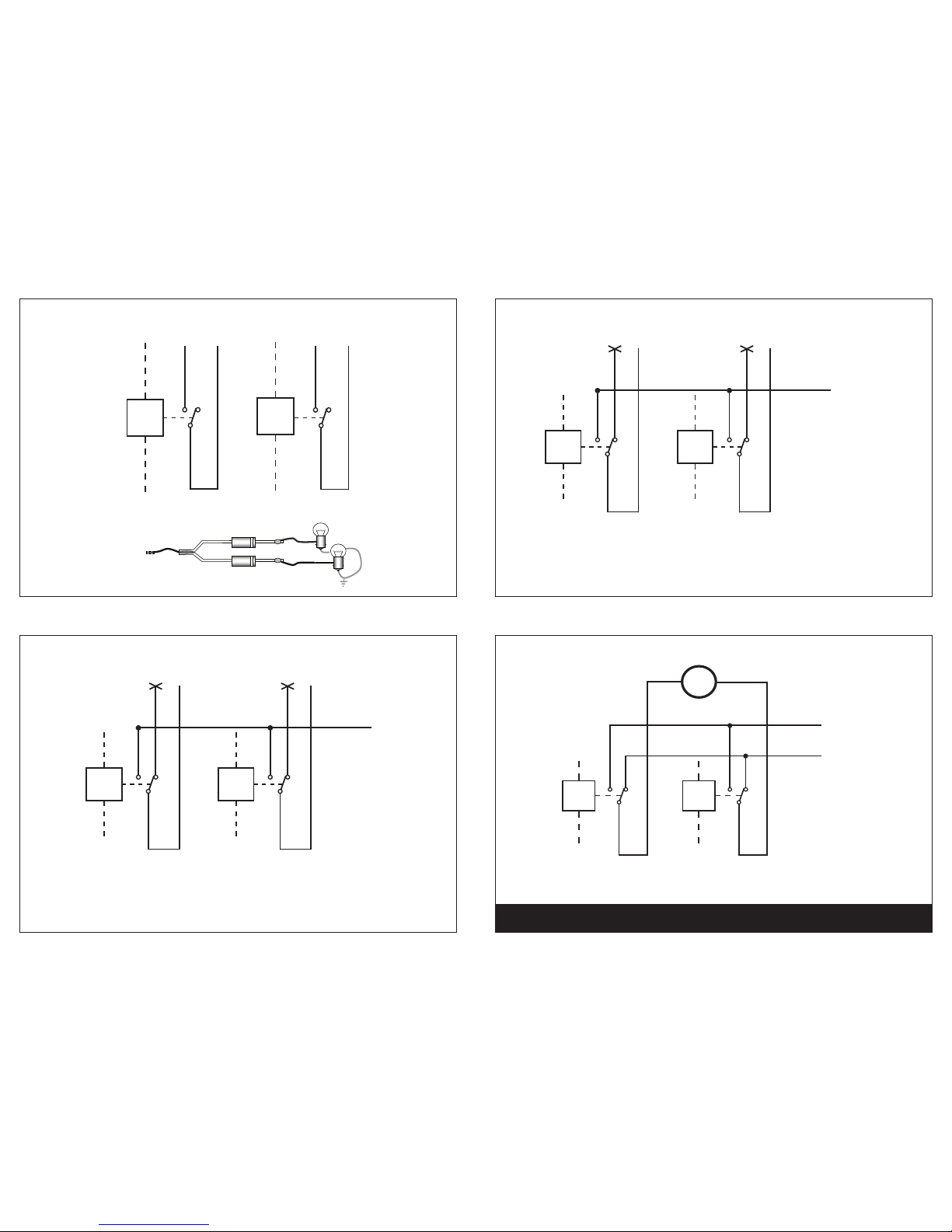
If main unit is connected to servomotors, connect Brown wire to +12V, Pink and Violet wires to GROUND
Diagram for locking, unlocking open
Diagram for locking, unlocking
Connection main unit directly to servomotors for locking, unlocking
BENE 102A
Lights connection
Page 6
Page 7
Page 5
Trunk
Relay
Trunk
Relay
green
green
yellow
yellow
+12V
GROUND
OR
Diagram for trunk open
Unlocking
Relay
brown
white
violet
Locking
Relay
brown
blue
pink
negative locking, unlocking
brown
GROUND
Unlocking
Relay
brown
white
violet
Locking
Relay
brown
blue
pink
positive locking, unlocking
brown
+12V
Unlocking
Relay
brown
white
violet
Locking
Relay
brown
blue
pink
locking, unlocking with positive impulse
brown
GROUND
M
+12V
orange
NOTE:
The rectifying diode not includes into set.
 Loading...