


xpR-10C
BendPak xpR-10C, XpR-10CX, XpR-10ACX, XpR-12C, XPR-15C Installation And Operation Manual
...
INSTALLATION AND OPERATION MANUAL
10,000 POUND CAPACITY
12,000 POUND CAPACITY
15,000 POUND CAPACITY
18,000 POUND CAPACITY
SURFACE MOUNTED
TWO-POST LIFTS
MODELS:
XPR-10C
XPR-10CX
XPR-10AC
XPR-10ACX
XPR-12C
XPR-15C
XPR-18C
VERSION A
PLEASE READ THE ENTIRE CONTENTS OF THIS MANUAL PRIOR TO
INSTALLATION AND OPERATION. BY PROCEEDING YOU AGREE THAT
YOU FULLY UNDERSTAND AND COMPREHEND THE FULL CONTENTS OF
THIS MANUAL. FORWARD THIS MANUAL TO ALL OPERATORS. FAILURE TO
OPERATE THIS EQUIPMENT AS DIRECTED MAY CAUSE INJURY OR DEATH.
MAN REV F 02-08-11
pn# 5900043
Keep this operation manual near the
machine at all times. Make sure that
ALL USERS read this manual.
SHIPPING DAMAGE CLAIMS
When this equipment is shipped, title passes to the
purchaser upon receipt from the carrier. Consequently,
claims for the material damaged in shipment must be made
by the purchaser against the transportation company at the
time shipment is received.
BE SAFE
Your new lift was designed and built with safety in mind.
However, your overall safety can be increased by proper
training and thoughtful operation on the part of the operator.
DO NOT operate or repair this equipment without reading
this manual and the important safety instructions shown
inside.
1645 Lemonwood Dr.
Santa Paula, CA. 93060, USA
Toll Free 1-800-253-2363
Tel: 1-805-933-9970
Fax: 1-805-933-9160
wwwbendpak.com
1
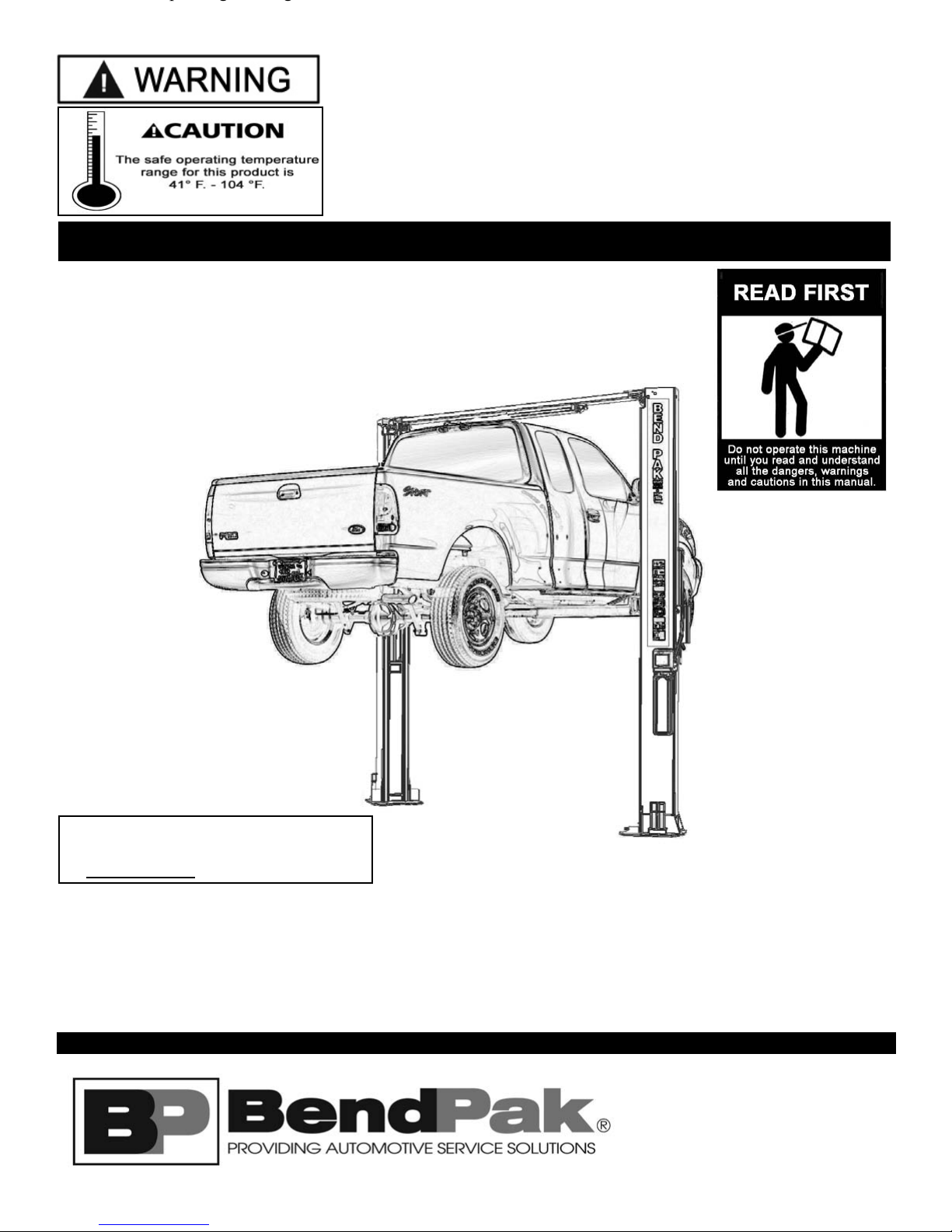
TWO-POST
SURFACE MOUNTED
AUTO AND LIGHT DUTY TRUCK LIFT
This instruction manual has been prepared especially for you.
Your new lift is the product of over 35 years of continuous research, testing and development;
it is the most technically advanced lift on the market today.
READ THIS ENTIRE MANUAL BEFORE INSTALLATION & OPERATION BEGINS.
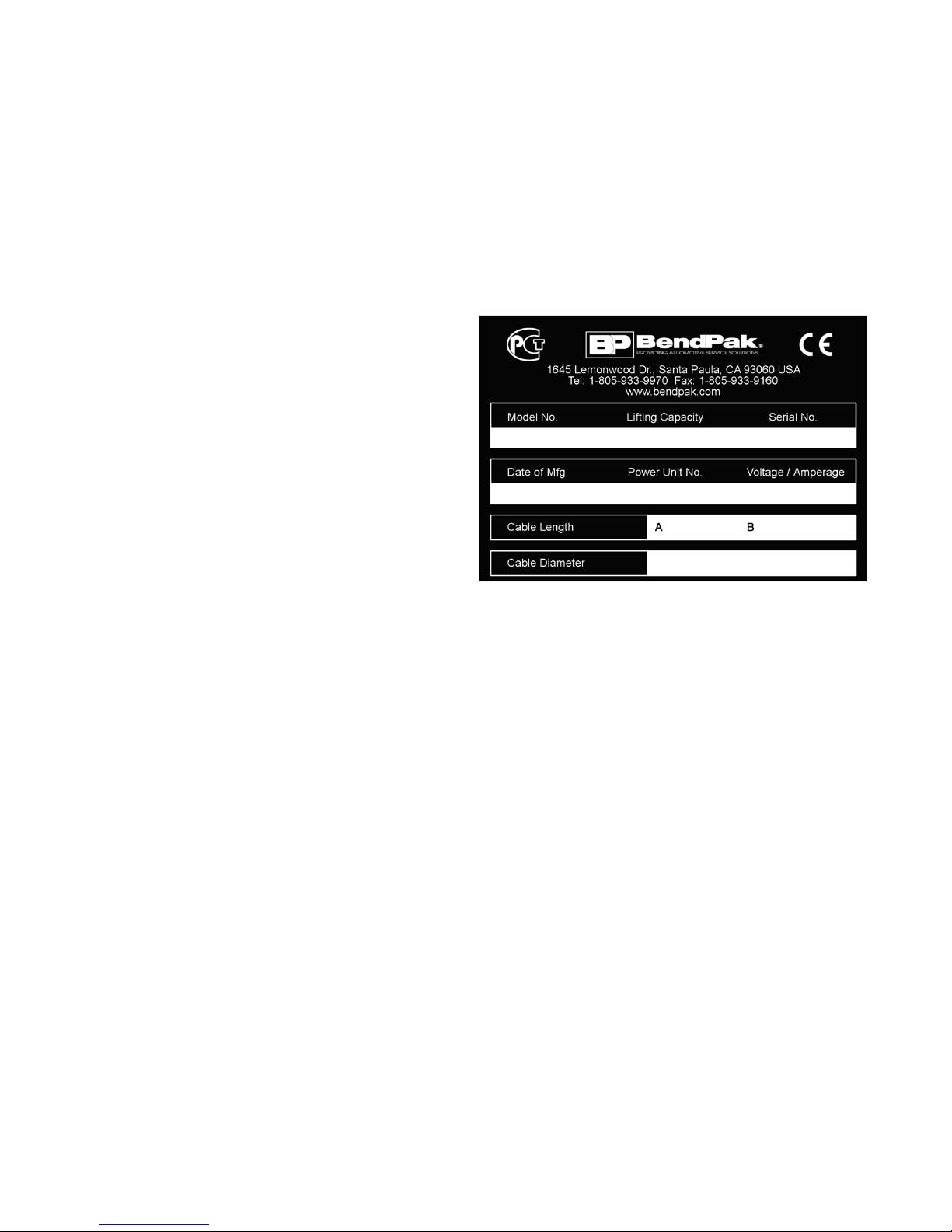
RECORD HERE THE LIFT AND
POWER UNIT INFORMATION WHICH IS
LOCATED ON THE SERIAL NUMBER
DATA PLATES ON THE LIFT AND
ON THE POWER UNIT
Power Unit Model # _____________
Power Unit Date Of Mfg. _____________
Power Unit Serial # _____________
This information is required when
calling for parts or warranty issues.
PRODUCT WARRANTY
BendPak 2-Post Lifts are covered under warranty for five years on equipment structure, to be free of defects in material
and workmanship. Power units, hydraulic cylinders, and all other assembly components such as turnplates, slip plates,
cables, chains, valves, switches etc. are covered under warranty for one year against defects in material or
workmanship under normal use. BendPak Inc. shall repair or replace at their option for the warranty period those parts
returned to the factory freight prepaid which prove upon inspection to be defective. BendPak Inc. will pay labor costs for
the first 12 months only on parts returned as previously described.
The warranty does not extend to...
t defects caused by ordinary wear, abuse, misuse, shipping damage, improper
installation, voltage or lack of required maintenance;
t damages resulting from purchaser’s neglect or failure to operate products in accordance with
instructions provided in the owner’s manual (s) and/or other accompanying instructions supplied;
t normal wear items or service normally required to maintain the product in a safe operating condition;
t any component damaged in shipment;
t other items not listed but may be considered general wear parts;
t damage caused by rain, excessive humidity, corrosive environments or other contaminants.
THESE WARRANTIES DO NOT EXTEND TO ANY COSMETIC DEFECT NOT INTERFERING WITH EQUIPMENT
FUNCTIONALITY OR ANY INCIDENTAL, INDIRECT, OR CONSEQUENTIAL LOSS, DAMAGE, OR EXPENSE THAT
MAY RESULT FROM ANY DEFECT, FAILURE, OR MALFUNCTION OF A BENDPAK INC. PRODUCT OR THE
BREACH OR DELAY IN PERFORMANCE OF THE WARRANTY.
WARRANTY IS NOT VALID UNLESS
WARRANTY CARD IS RETURNED.
22
IMPORTANT NOTICE
Do not attempt to install this lift if you have never been
trained on basic automotive lift installation procedures.
Never attempt to lift components without proper lifting
tools such as forklift or cranes. Stay clear of any moving
parts that can fall and cause injury. These instructions
must be followed to insure proper installation and
operation of your lift. Failure to comply with these
instructions can result in serious bodily harm and void
product warranty. Manufacturer will assume no liability for
loss or damage of any kind, expressed or implied
resulting from improper installation or use of this product.
PLEASE READ ENTIRE MANUAL
PRIOR TO INSTALLATION.
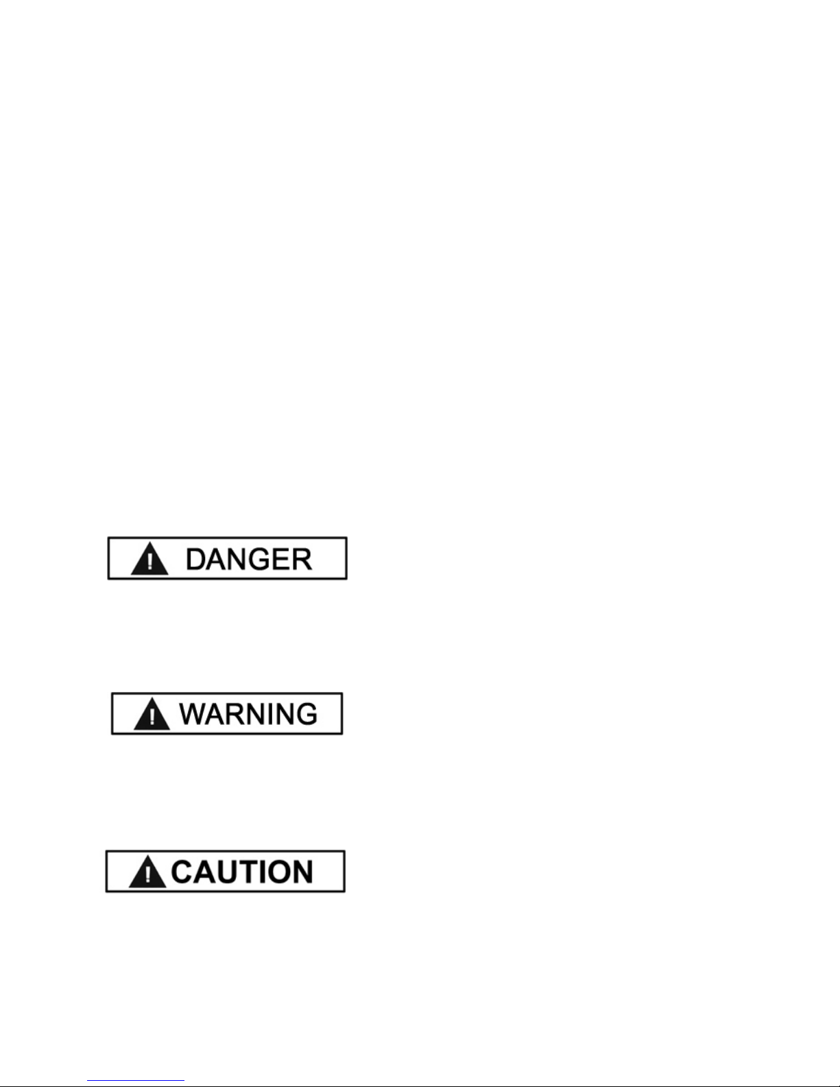
DEFINITIONS OF
HAZARD LEVELS
Identify the hazard levels used in this manual with the
following definitions and signal words:
OWNER’S RESPONSIBILITY
To maintain the lift and user safety, the responsibility of
the owner is to read and follow these instructions:
tFollow all installation and operation instructions.
tMake sure installation conforms to all applicable Local,
State, and Federal Codes, Rules, and Regulations;
such as State and Federal OSHA Regulations and
Electrical Codes.
tCarefully check the lift for correct initial function.
t Read and follow the safety instructions. Keep them
readily available for machine operators.
tMake certain all operators are properly trained, know
how to safely and correctly operate the unit, and are
properly supervised.
tAllow unit operation only with all parts in place and
operating safely.
t Carefully inspect the unit on a regular basis and
perform all maintenance as required.
tService and maintain the unit only with authorized or
approved replacement parts.
tKeep all instructions permanently with the unit and
all decals on the unit clean and visible.
DANGER !
Watch for this symbol: It Means: Immediate hazards
which will result in severe personal injury or death.
WARNING !
Watch for this symbol: It Means: Hazards or unsafe
practices which could result in severe personal
injury or death.
CAUTION !
Watch for this symbol: It Means: Hazards or unsafe
practices which may result in minor personal injury,
product or property damage.
BEFORE YOU BEGIN
Receiving:
The shipment should be thoroughly inspected as soon as it
is received. The signed bill of lading is acknowledgement by
the carrier of receipt in good condition of shipment covered
by your invoice. If any of the goods called for on this bill of
lading are shorted or damaged, do not accept them until the
carrier makes a notation on the freight bill of the shorted or
damaged goods. Do this for your own protection.
NOTIFY THE CARRIER AT ONCE if any hidden loss or
damage is discovered after receipt and request the carrier
to make an inspection. If the carrier will not do so, prepare
a signed statement to the effect that you have notified the
carrier (on a specific date) and that the carrier has failed to
comply with your request.
IT IS DIFFICULT TO COLLECT FOR LOSS OR DAMAGE
AFTER YOU HAVE GIVEN THE CARRIER A CLEAR
RECEIPT. File your claim with the carrier promptly. Support
your claim with copies of the bill of lading, freight bill,
invoice, and photographs, if available. Our willingness to
assist in helping you process your claim does not make
BendPak responsible for collection of claims or
replacement of lost or damaged materials.
33

TABLE OF CONTENTS
Contents Page No.
Warranty / Serial Number Information . . . . . . . . . . . . . . . . . . . . . . . . . . . . . . . . . . . . . . . . . . . . . . . . . . . . . . . . . . . . . .2
Definitions of Hazard Levels . . . . . . . . . . . . . .. . . . . . . . . . . . . . . . . . . . . . . . . . . . . . . . . . . . . . . . . . . . . . . . . . . . . . . 3
Owner’s Responsibility . . . . . . . . . . . . . . .. . . . . . . . . . . . . . . . . . . . . . . . . . . .. . . . . . . . . . . . . . . . . . . . . . . . . . . . . . . . .3
Before You Begin. . . . . . . . . . . . . . . . . . . . . . . . . . . . . . . . . . . . . . . . . . . . . . . . . . . . . . . . . . . . . . . . . . . . . . . . . . . . . . 3
Installer/Operator Agreement/ Protective Equipment. . . . . . . . . . . . . . . . . . . . . . . . . . . . . . . . . . . . . . . . . . . . . . . . . . 5
Introduction. . . . . . . . . . . . . . . . . . . . . . . . . . . . . . . . . . . . . . . . . . . . . . . . . . . . . . . . . . . . . . . . . . . . . . . . . . . . . . . . . . . 6
Safety / Warning Instructions . . . . . . . . . . . . . . . . . . . . . . . . . . . . . . . . . . . . . . . . . . . . . . . . . . . . . . . . . . . . . . . . . . . . . 6
Tools Required. . . . . . . . . . . . . . . . . . . . . . . . . . . . . . . . . . . . . . . . . . . . . . . . . . . . . . . . . . . . . . . . . . . . . . . . . . . . . . . . .7
Step 1 / Selecting Site . . . . . . . . . . . . . . . . . . . . . . . . . . . . . . . . . . . . . . . . . . . . . . . . . . . . . . . . . . . . . . . . . . . . . . . . . . .7
Step 2 / Floor Requirements . . . . . . . . . . . . . . . . . . . . . . . . . . . . . . . . . . . . . . . . . . . . . . . . . . . . . . . . . . . . . . . . . . . .7
Concrete Specifications. . . . . . . . . . . . . . . . . . . . . . . . . . . . . . . . . . . . . . . . . . . . . . . . . . . . . . . . . . . . . . . . . . . . . . . 7
Assembly View / Description of Parts . . . . . . . . . . . . . . . . . . . . . . . . . . . . . . . . . . . . . . . . . . . . . . . . . . . . . . . . . . . . . . 8
Step 3 / Column Preparation. . . . . . . . . . . . . . . . . . . . . . . . . . . . . . . . . . . . . . . . . . . . . . . . . . . . . . . . . . . . . . . . 9-10
Step 4 / Site Layout . . . . . . . . . . . . . . . . . . . . . . . . . . . . . . . . . . . . . . . . . . . . . . . . . . . . . . . . . . . . . . . . . . . . . . . . .11
Floor Plan / Specifications /Power Unit Location . . . . . . . . . . . . . . . . . . . . . . . . . . . . . . . . . . . . . . . . . . . .12
Step 5 / Installing Powerside Column. . . . . . . . . . . . . . . . . . . . . . . . . . . . . . . . . . . . . . . . . . . . . . . . . . . . . . . .13
Step 6 / Installing Offside Column. . . . . . . . . . . . . . . . . . . . . . . . . . . . . . . . . . . . . . . . . . . . . . . . . . . . . . . . .13
Step 7 / Mounting The Top Trough Assembly . . . . . . . . . . . . . . . . . . . . . . . . . . . . . . . . . . . . . . . . . . . . . . . . . . . . .14
Step 8 / Mounting The Hydraulic Power Unit . . . . . . . . . . . . . . . . . . . . . . . . . . . . . . . . . . . . . . . . . . . . . . . . . . . . . . . . 15
Step 9 / Installing the Safeties and Safety Cable . . . . . . . . . . . . . . . . . . . . . . . . . . . . . . . . . . . . . . . . . .16-17
Step 10 / Installing Hydraulic Lines . . . . . . . .. . . . . . . . . . . . . . . . . . . . . . . . . . . . . . . . . . . . . . . . . . . . . . . . . . . . . 17-18
Step 11 / Routing the Equalizer Cables . . . . . . . . . . . . . . . . . . . . . . . . . . . . . . . . . . . . . . . . . . . . . . . . . . . . . . . 18
Step 12 / Installing Overhead Microswitch . . . . . . . . . . . . . . . . . . . . . . . . . . . . . . . . . . . . . . . . . . . . . . . . . . . .19
Step 13 / Installing Power Unit Hose Assembly and Powerside Safety Cover . . . . . . . . . . . . . . . . . . . . . . . . . . . . . . . .20
Step 14 / Installing the Lift Arms . . . . . . . . . . . . . . . . . . . . . . . . . . . . . . . . . . . . . . . . . . . . . . . . . . . . . . . 21-23
Carriage Stop Bolt Installation Warning. . . . . . . . . . . . . . . . . . . . . . . . . . . . . . . . . . . . . . . . . . . . . . . . . . . . . . . . . .24
Step 15 / Hydraulic Power Unit Hook-up . . . . . . . . . . . . . . . . . . . . . . . . . . . . . . . . . . . . . . . . . . . . . . . . . . . . . . . . . . . . . .25-28
Step 16 / Lift Start Up Final Adjustments . . . . . . . . . . . . . . . . . . . . . . . . . . . . . . . . . . . . . . . . . . . . . . . . . . . . . . . . . . . . . 28
Post Installation Checklist . . . . . . . . . . . . . . . . . . . . . . . . . . . . . . . . . . . . . . . . . . . . . . . . . . . . . . . . . . . . . . . . . . . . . . . . . .29
Step 17 / Lubrication. . . . . . . . . . . . . . . . . . . . . . . . . . . . . . . . . . . . . . . . . . . . . . . . . . . . . . . . . . . . . . . . . . . . . . . . . . . .29
Step 18 Bleeding . . . . . . . . . . . . . . . . . . . . . . . . . . . . . . . . . . . . . . . . . . . . . . . . . . . . . . . . . . . . . . . . . . . . . . . . . . . .29
Optional Equipment Installation. . . . . . . . . . . . . . . . . . . . . . . . . . . . . . . . . . . . . . . . . . . . . . . . . . . . . . . . . . . . . . . . . . .30-31
Step 19 / Operation/ Maintenance . . . . . . . . . . . . . . . . . . . . . . . . . . . . . . . . . . . . . . . . . . . . . . . . . . . . . . . . . . . . .32-43
Troubleshooting Guide . . . . . . . . . . . . . . . . . . . . . . . . . . . . . . . . . . . . . . . . . . . . . . . . . . . . . . . . . . . . . . . . . . . . . . .44-47
Maintenance Records. . . . . . . . . . . . . . . . . . . . . . . . . . . . . . . . . . . . . . . . . . . . . . . . . . . . . . . . . . . . . . . . . . . .48
Installation Form . . . . . . . . . . . . . . . . . . . . . . . . . . . . . . . . . . . . . . . . . . . . . . . . . . . . . . . . . . . . . . . . . . . . . . . . . . . . . .49
Part Number Lists . . . . . . . . . . . . . . . . . . . . . . . . . . . . . . . . . . . . . . . . . . . . . . . . . . . . . . . . . . . . . . . . . . . . . . . . . 50-59
44
INSTALLER / OPERATOR
PLEASE READ AND FULLY
UNDERSTAND.
BY PROCEEDING YOU AGREE TO
THE FOLLOWING.
tI have visually inspected the site where the lift is to be
installed and verified the concrete to be in good
condition and free of cracks or other defects. I understand
that installing a lift on cracked or defective concrete could
cause lift failure resulting in personal injury or death.
t I understand that a level floor is required for proper
installation and level lifting.
t I understand that I am responsible if my floor is of
questionable slope and that I will be responsible for all
charges related to pouring a new level concrete slab if
required and any charges.
t I understand that BendPak lifts are supplied with
concrete fasteners meeting the criteria of the American
National Standard “Automotive Lifts - Safety Requirements
for Construction, Testing, and Validation” ANSI/ALI
ALCTV-2006, and that I will be responsible for all charges
related to any special regional structural and/or seismic
anchoring requirements specified by any other agencies
and/or codes such as the Uniform Building Code (UBC)
and/or International Building Code (IBC).
t I will assume full responsibility for the concrete floor
and condition thereof, now or later, where the above
equipment model(s) are to be installed. Failure to follow
danger, warning, and caution instructions may lead to
serious personal injury or death to operator or bystander
or damage to property.
t I understand that BendPak lifts are designed to be
installed in indoor locations only. Failure to follow
installation instructions may lead to serious personal
injury or death to operator or bystander or damage to
property or lift.
Failure to follow danger, warning, and caution
instructions may lead to serious personal injury or death
to operator or bystander or damage to property.
Please read entire manual prior to installation.
Do not operate this machine until you read and
understand all the dangers, warnings and cautions
in this manual. For additional copies
or further information, contact:
BendPak Inc. / Ranger Products
1645 Lemonwood Dr.
Santa Paula, CA. 93060
1-805-933-9970
www.bendpak.com
INSTALLER / OPERATOR
PROTECTIVE EQUIPMENT
Personal protective equipment helps makes installation
and operation safer, however, it does not take the place
of safe operating practices. Always wear durable work
clothing during any installation and/or service activity.
Shop aprons or shop coats may also be worn, however
loose fitting clothing should be avoided. Tight fitting
leather gloves are recommended to protect technician
hands when handling parts. Sturdy leather work shoes
with steel toes and oil resistant soles should be used by
all service personnel to help prevent injury during typical
installation and operation activities.
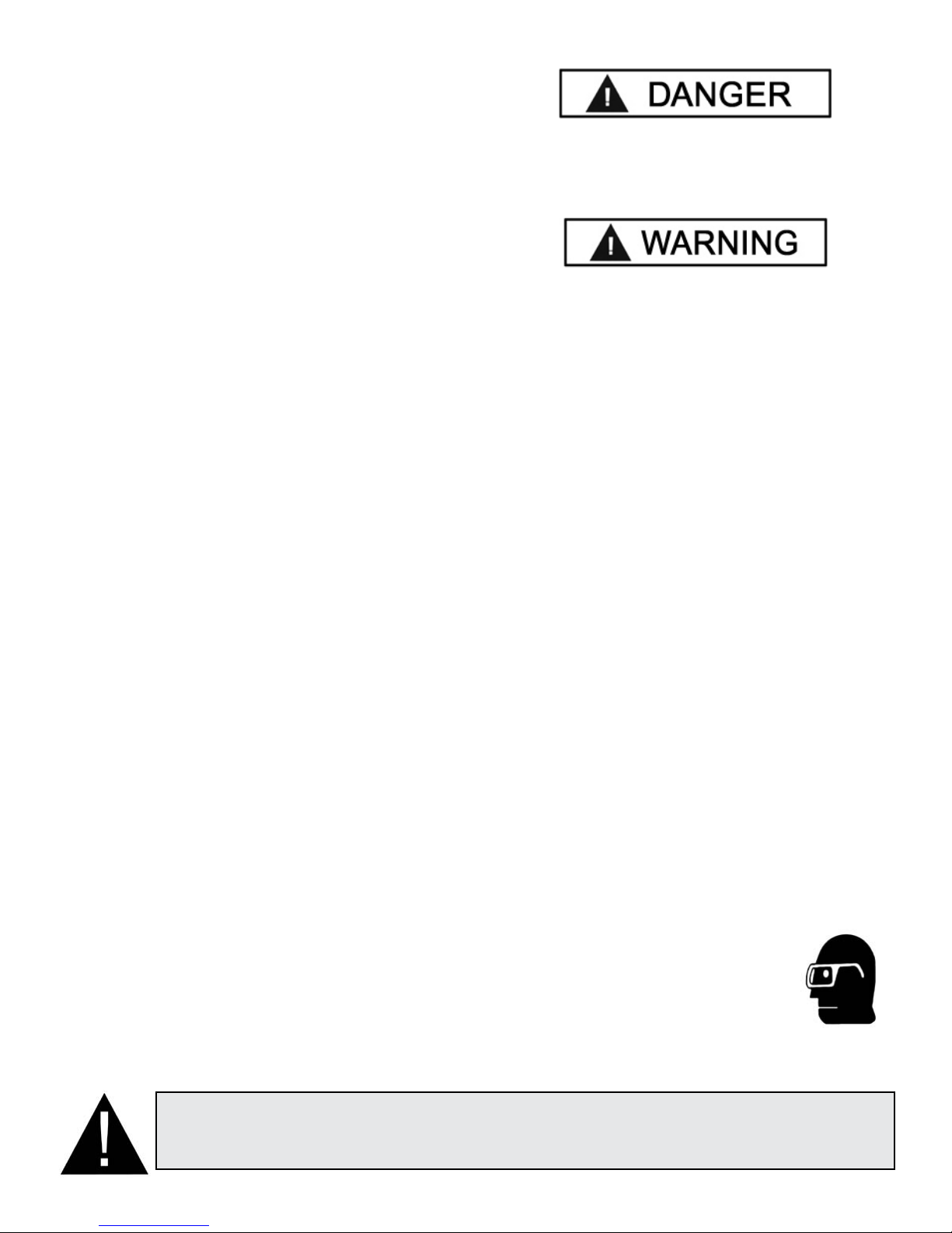
Eye protection is essential during installation and
operation activities. Safety glasses with side shields,
goggles, or face shields are acceptable.
Back belts provide support during lifting
activities and are also helpful in providing
worker protection. Consideration should
also be given to the use of hearing
protection if service activity is performed in an enclosed
area, or if noise levels are high.
THIS SYMBOL POINTS OUT IMPORTANT SAFETY INSTRUCTIONS WHICH IF NOT FOLLOWED
COULD ENDANGER THE PERSONAL SAFETY AND/OR PROPERTY OR YOURSELF AND OTHERS
AND CAN CAUSE PERSONAL INJURY OR DEATH. READ AND FOLLOW ALL INSTRUCTIONS IN
THIS MANUAL BEFORE ATTEMPTING TO OPERATE THIS MACHINE.
55
INTRODUCTION
1. Carefully remove the crating and packing
materials. CAUTION! Be careful when cutting steel
banding material as items may become loose and fall
causing personal harm or injury.
2. Check the voltage, phase and proper amperage
requirements for the motor shown on the motor plate.
Wiring should be performed by a certified electrician
only.
IMPORTANT SAFETY INSTRUCTIONS !
Read these safety instructions entirely!
IMPORTANT NOTICE !
Do not attempt to install this lift if you have never been trained on basic automotive lift installation procedures.
Never attempt to lift components without proper lifting tools such as forklift or cranes.
Stay clear of any moving parts that can fall and cause injury.
1. READ AND UNDERSTAND all safety warning
procedures before operating lift.
2. KEEP HANDS AND FEET CLEAR. Remove hands and
feet from any moving parts. Keep feet clear of lift when
lowering. Avoid pinch points.
3. KEEP WORK AREA CLEAN. Cluttered work areas
invite injuries.
4. Consider work area environment. Do not expose
equipment to rain. DO NOT use in damp or wet locations.
Keep area well lighted.
5. ONLY TRAINED OPERATORS should operate this lift.
All non-trained personnel should be kept away from work
area. Never let non-trained personnel come in contact with,
or operate lift.
12. GUARD AGAINST ELECTRIC SHOCK. This lift must
be grounded while in use to protect the
operator from electric shock. Never connect
the green power cord wire to a live terminal.
This is for ground only.
13. DANGER! The power unit used on this lift contains high
voltage. Disconnect power at the receptacle
before performing any electrical repairs.
Secure plug so that it cannot be
accidentally plugged in during service.
14. WARNING! RISK OF EXPLOSION. This equipment
has internal arcing or sparking parts which
should not be exposed to flammable vapors.
This machine should not be located in a
recessed area or below floor level.
6. USE LIFT CORRECTLY. Use lift in the proper manner.
Never use lifting adapters other than what is approved by the
manufacturer.
7. DO NOT override self-closing lift controls.
8. REMAIN CLEAR of lift when raising or lowering vehicle.
9. CLEAR AREA if vehicle is in danger of falling.
10. ALWAYS INSURE that the safeties are engaged before
any attempt is made to work on or near vehicle.
11. DRESS PROPERLY. Non-skid steel-toe footwear is
recommended when operating lift.
15. MAINTAIN WITH CARE. Keep lift clean for better and
safer performance. Follow manual for proper lubrication
and maintenance instructions. Keep control handles and/or
buttons dry, clean and free from grease and oil.
16. STAY ALERT. Watch what you are doing. Use common
sense. Be aware.
17. CHECK FOR DAMAGED PARTS. Check for alignment
of moving parts, breakage of parts or any condition that may
affect its operation. Do not use lift if any component is broken
or damaged.
18. NEVER remove safety related components from the lift.
Do not use lift if safety related components are damaged
or missing.
66
TOOLS REQUIRED
t Rotary Hammer Drill or Similar
t3/4” Masonry Bit
tHammer
t4 Foot Level
tOpen-End Wrench Set: SAE/Metric
t Socket And Ratchet Set: SAE/Metric
t Hex-Key / Allen Wrench Set
tLarge Crescent Wrench
tLarge Pipe Wrench
tCrow Bar
tChalk Line
t Medium Flat Screwdriver
tTape Measure: 25 Foot Minimum
tNeedle Nose Pliers
IMPORTANT NOTICE!
These instructions must be followed to insure proper installation and operation of your lift. Failure
to comply with these instructions can result in serious bodily harm and void product warranty.
Manufacturer will assume no liability for loss or damage of any kind, expressed or implied resulting
from improper installation or use of this product.
PLEASE READ ENTIRE MANUAL PRIOR TO INSTALLATION !
STEP 1
(Selecting Site)
Before installing your new lift, check the following.
1. LIFT LOCATION: Always use architects plans when
available. Check layout dimension against floor plan
requirements making sure that adequate space if
available.
2. OVERHEAD OBSTRUCTIONS: The area where the
lift will be located should be free of overhead
obstructions such as heaters, building supports, electrical
lines etc.
3. DEFECTIVE FLOOR: Visually inspect the site where
the lift is to be installed and check for cracked or
defective concrete.
A level floor is suggested for proper use and
installation and level lifting. If a floor is of questionable
slope, consider a survey of the site and/or the possibility
of pouring a new level concrete slab.
t DO NOT install or use this lift on any asphalt surface
or any surface other than concrete.
t DO NOT install or use this lift on expansion seams
or on cracked or defective concrete.
t DO NOT install or use this lift on a second / elevated
floor without first consulting building architect.
t DO NOT install or use this lift outdoors.
CONCRETE SPECIFICATIONS
4. OPERATING TEMPERATURE. Operate lift only
between temperatures of 41° -104° F.
5. Lift is designed for INDOOR INSTALLATION ONLY.
STEP 2
(Floor Requirements)
LIFT MODEL CONCRETE REQUIREMENTS
10,000 Lb Models 4” Min. Thickness / 3,000 PSI
12,000 Lb Models 6” Min. Thickness / 3,000 PSI
15,000 Lb Models 6” Min. Thickness / 3,000 PSI
18,000 Lb Models 8” Min. Thickness / 3,000 PSI
DANGER!
This lift must be installed on a solid level concrete
floor with no more than 3-degrees of slope. Failure
to do so could cause personal injury or death.
All models MUST be installed on 3000 PSI concrete only
conforming to the minimum requirements shown above.
New concrete must be adequately cured by at least
28 days minimum.
IMPORTANT NOTE:
BendPak lifts are supplied with installation instructions and concrete fasteners meeting the criteria as prescribed
by the American National Standard "Automotive Lifts - Safety Requirements for Construction, Testing, and
Validation" ANSI/ALI ALCTV-2006. Lift buyers are responsible for any special regional structural and/or seismic
77
When removing the lift from shipping angles pay close attention as the posts
can slide and can cause injury. Prior to removing the bolts make sure the
posts are held securely by a fork lift or some other heavy lifting devise.
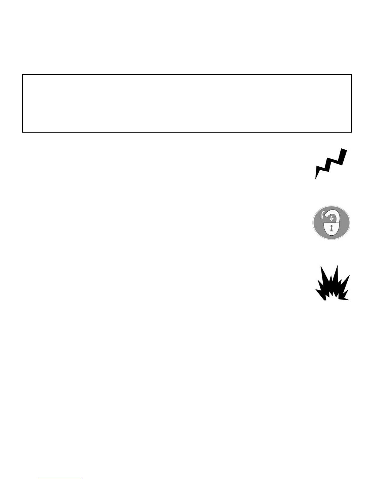
PARTS INVENTORY
Be sure to take a complete inventory of parts prior to beginning installation.
Description Qty
Top Trough Assembly with Trip Stop and Equalizer Pulleys Installed 1
Front Arm Assembly 2
Rear Arm Assembly 2
Offside Column with Lift Head Assembly 1
Powerside Column with Lift Head Assembly 1
Hydraulic Cylinder 2
Parts Box
Parts Bag
Hydraulic Power Unit 1
(Packing List Enclosed)
(Packed in Part Box) 1
1
88
STEP 3
(Column Preparation)
COMPLETE THE FOLLOWING
PRIOR STANDING UP COLUMNS.
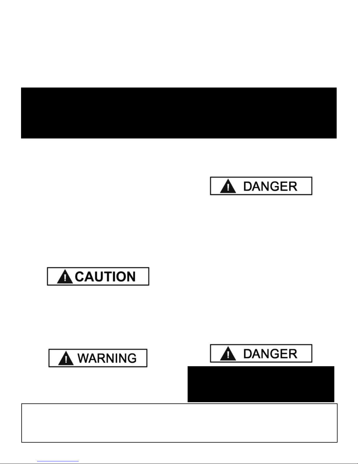
1. Slide carriage up Column to aid in Pulley removal and
Equalizer Cable routing. (See Fig 3.1)
Fig 3.1
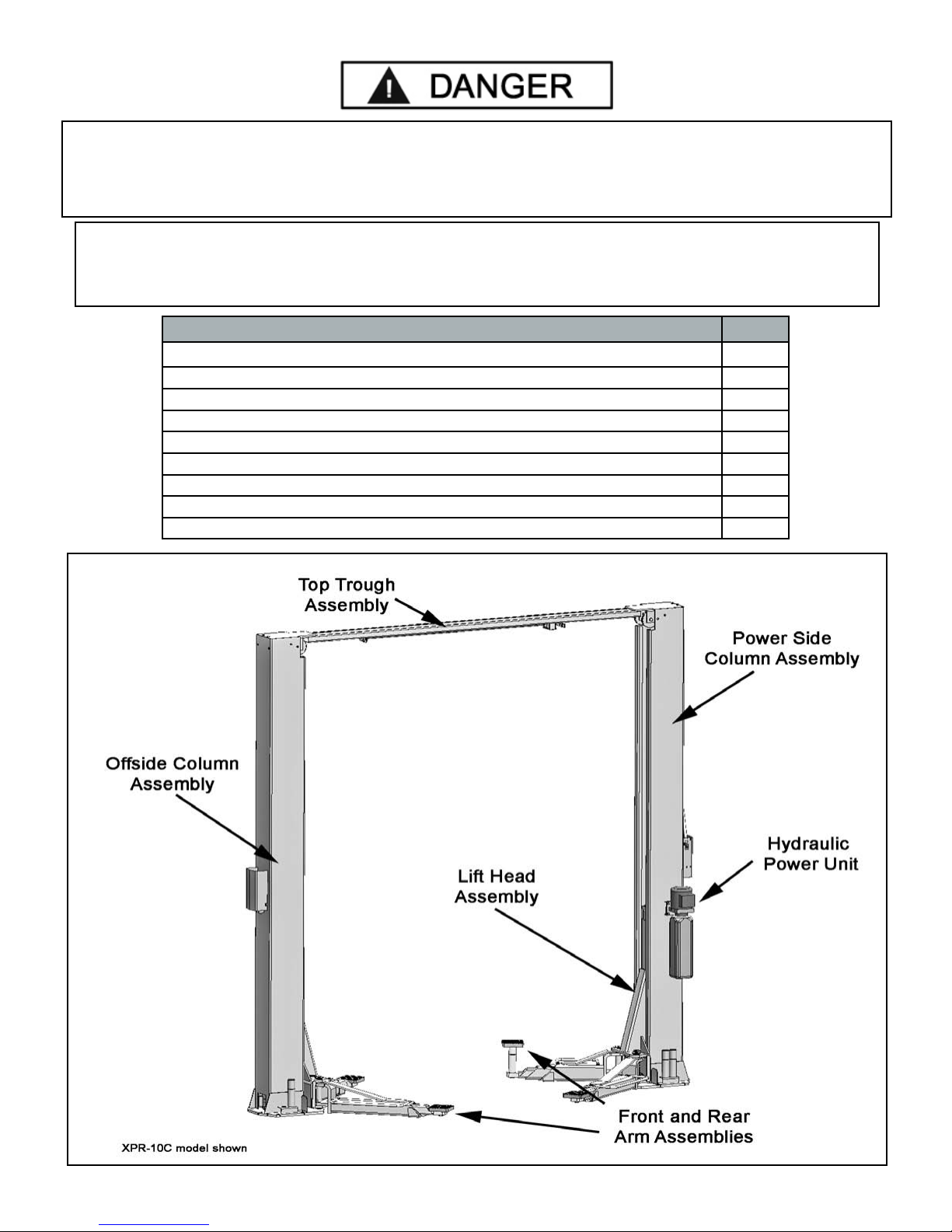
Fig 3.3
3. Feed threaded end of Cable up through carriage. Leave
excess cable resting on top of carriage until further steps are
required. (See Fig 3.4 and 3.5)
2. Remove Equalizer Cable Pulley. Route the plug end
of each Equalizer Cable around the bottom Pulley and
lock into Bottom Plate of Carriage. (Fig. 3.2)
Fig 3.2
(NOTE: Symmetrical models both Cables are same length.
Asymmetric models have two different length Cables.)
(See Fig. 3.3)
Fig 3.4
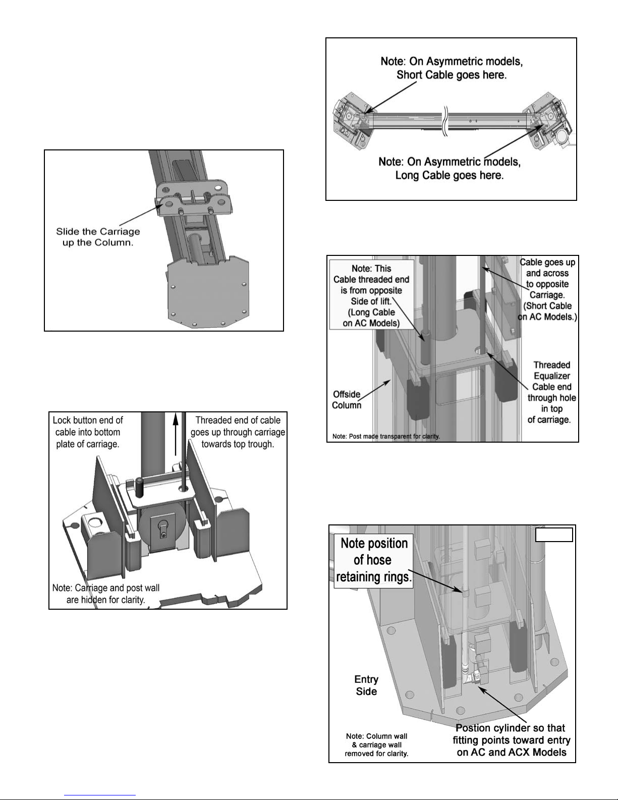
4. Install the Cylinder Fittings in Cylinder Ports. Pay
attention when installing the Cylinders in step three to ensure
that each Fitting points towards the entrance side of lift.
(See Fig 3.5)
Fig 3.5
99
Reminder: on AC Models rotate Cylinder so the
Hydraulic Fitting points as indicated in Fig 3.5.
6. Route both Hoses in their respective Columns PRIOR
to raising Columns to their vertical position. When routing
the Hydraulic Hose through the Columns, make sure to
route through the Retaining Clips welded inside each
Column. Make sure that the Hose is clear of any moving
parts. It may be necessary to tie Hose clear of
obstructions by using nylon tie straps or wire. Refer to
Step 10.
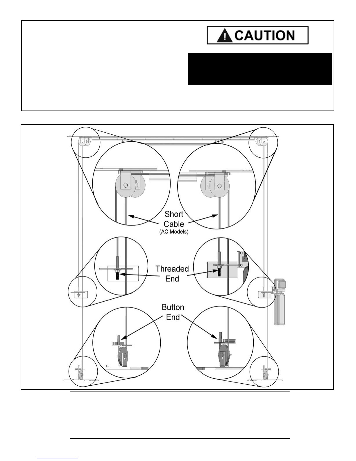
EQUALIZER CABLE ROUTING
CAUTION !
Be sure to route the Hydraulic Hoses through the
retaining clips welded inside each Column.
Fig 3.6
“C” models: both Equalizer Cables are the same length.
Top Trough Pulley ARE NOT staggered.
“AC” models: have one short and one long Equalizer Cable.
NOTE:
Top Trough Pulleys ARE staggered.
10
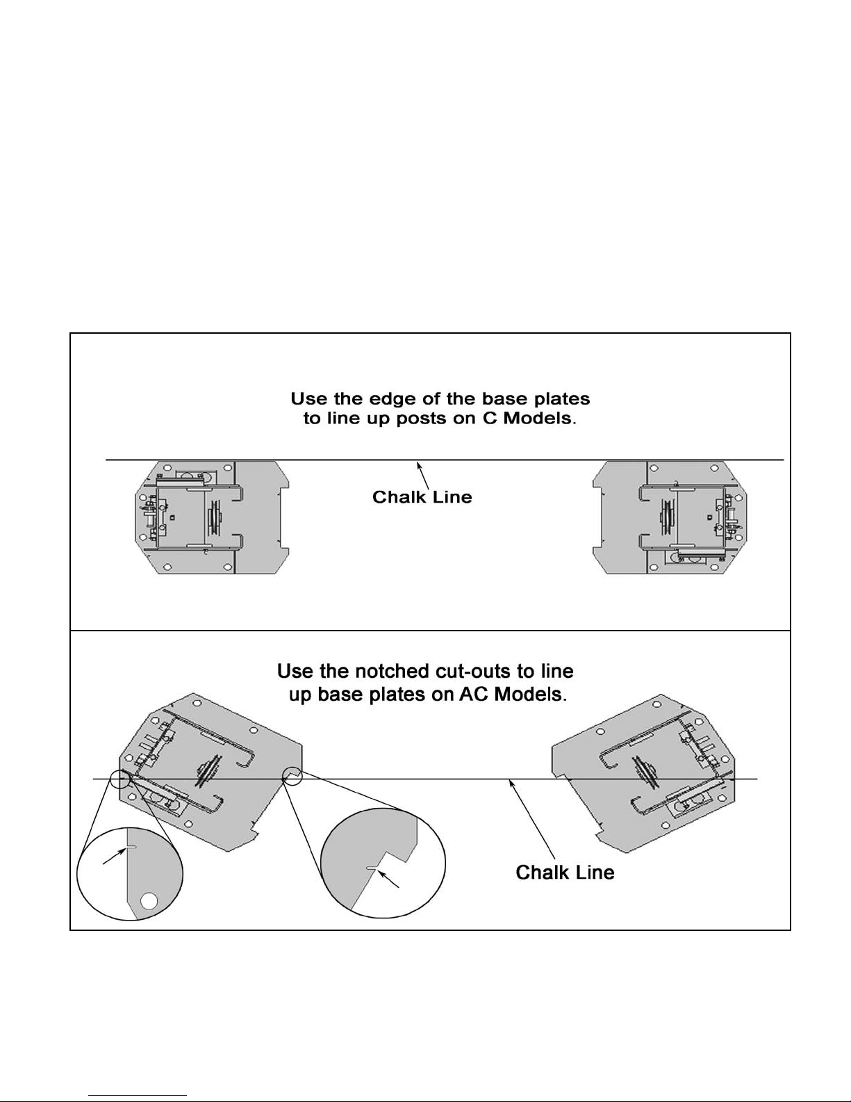
STEP 4
(Site Layout)
1. Determine which side will be the approach side.
4. After the Post locations are properly marked, use a
chalk or crayon to make an outline of the Posts on the floor
at each location using the Post Base Plates as a template.
(See Fig 4.1)
2. Now determine where the Power Unit will be located.
The POWERSIDE column has the power-unit mounting
bracket attached to the side.
3. Once a location is determined, use a carpenters chalk
line to layout a grid for the Post locations. Keep all
dimensions and squareness within 1/8” or malfunctioning of
the lift can occur. (See page 11)
5. Double check all dimensions and make sure that the
layout is perfectly square.
Fig 4.1.
1111
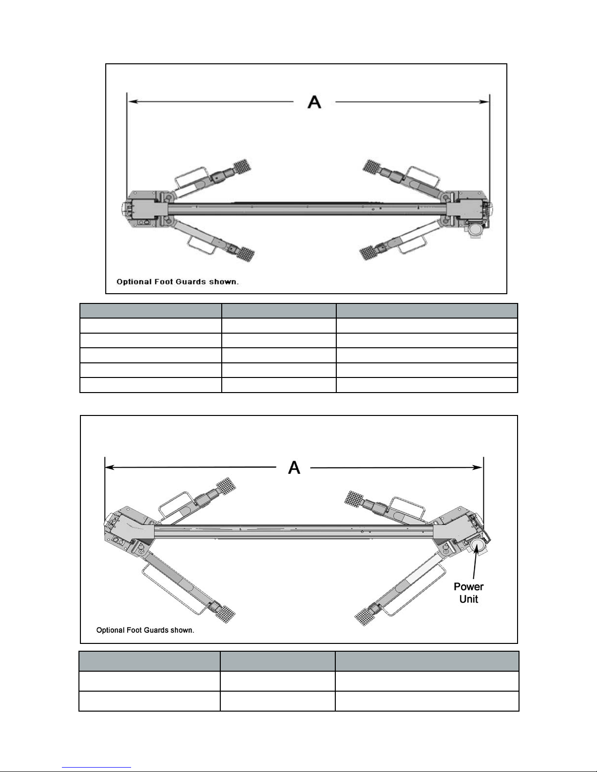
FLOOR PLAN
Model A Capacity
XPR-10C 3353 mm / 132” 10,000 LBS
XPR-10CX 3683 mm / 145” 10,000 LBS
XPR-12C 3937 mm / 155” 12,000 LBS
XPR-15C 3937 mm / 155” 15,000 LBS
XPR-18C 3937 mm / 155” 18,000 LBS
Model A Capacity
XPR-10AC 3354 mm / 132” 10,000 LBS
XPR-10ACX 3684 mm / 145” 10,000 LBS
1212
STEP 5
(Installing The POWERSIDE Column)
IMPORTANT NOTE:
BendPak lifts are supplied with installation
instructions and concrete fasteners meeting the
criteria as prescribed by the American National
Standard "Automotive Lifts - Safety Requirements for
Construction, Testing, and Validation" ANSI/ALI
ALCTV-2006. Lift buyers are responsible for any
special regional structural and/or seismic anchoring
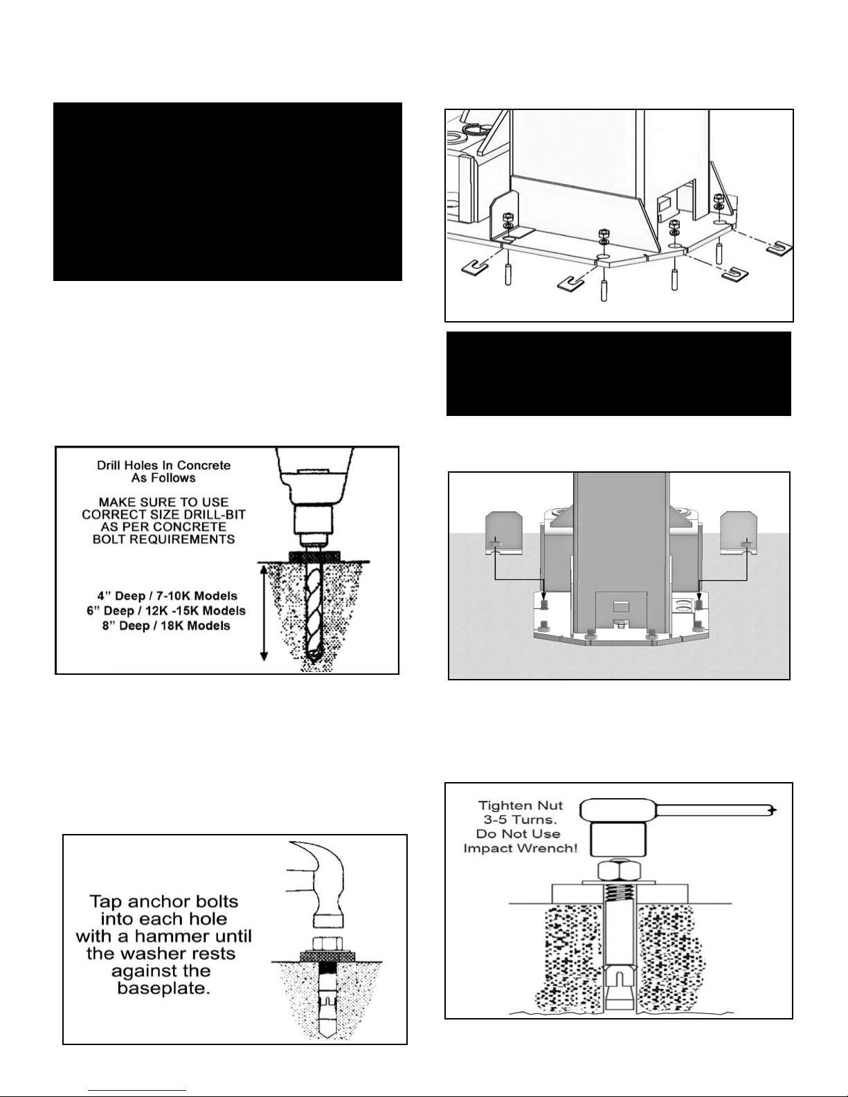
5. If shimming is required, insert the shims as necessary
under the Base Plate so that when the anchor bolts are
tightened, the Columns will be plumb. (See Fig. 5.3)
1. Before proceeding, double the check measurements
and make certain that the bases of each Column are
aligned with the chalk line.
2. Using the base plate on the POWERSIDE column as a
guide, drill each anchor hole in the concrete (approximately
4” deep for 10K models and 6” deep for 12K and15K;
8” for 18K models) using a rotary hammer drill and 3/4”
concrete drill-bit. To assure full holding power, do not ream
the hole or allow the drill to wobble. (See Fig. 5.1)
Fig 5.1
3. After drilling, remove dust thoroughly from each hole
making certain that the Column remains aligned with the
chalk line.
4. Assemble the washers and nuts on the anchors
then tap into each hole with a hammer until the washer
rests against the Base Plate. Be sure that if shimming is
required that enough threads are left exposed.
(See Fig. 5.2)
Fig 5.3
NOTE:
To ease installation of the Top Trough, it helps to keep
the anchor bolts loose on one of the Columns until the
Top Trough is mounted.
6. If installing the Optional Foot Guards, place foot guards
on left and right side as shown. (See Fig 5.4)
Fig 5.4
7. With the Foot Guards, shims and anchor bolts in place,
tighten by securing the nut to the base then turning 3-5 full
turns clockwise. DO NOT use an impact wrench for this
procedure. (See Fig. 5.5)
Fig 5.2
Fig 5.5
1313
STEP 6
(Mounting The OFFSIDE Column)
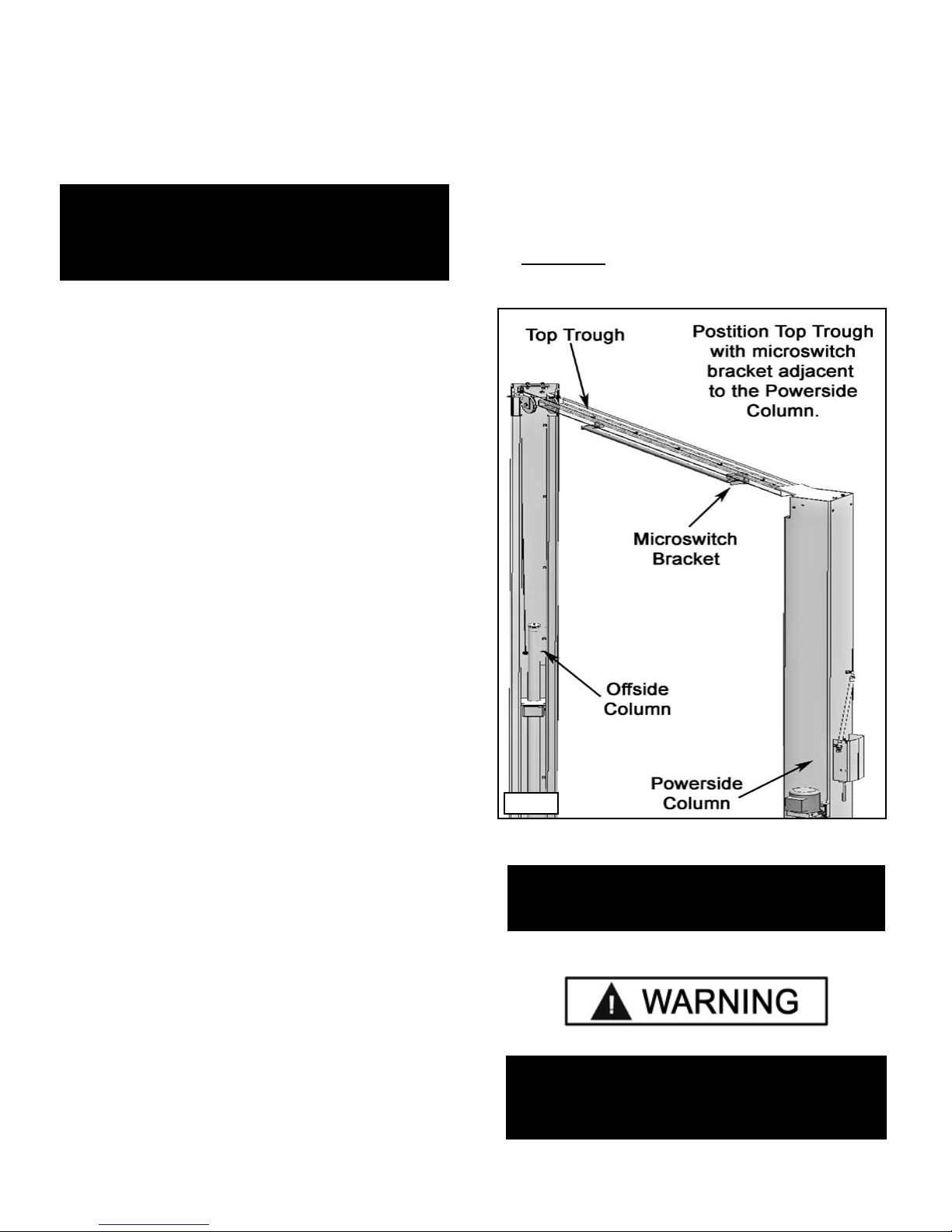
STEP 7
(Mounting the Top Trough Assembly)
1. Position the OFFSIDE Column at the designated chalk
locations and secure to the floor following the same
procedures as outlined in STEP FIVE; Items 1-6.
NOTE:
To ease the installation of the Top Trough, it helps
to keep the anchor bolts loose on one of the
Columns until the Top Trough is Mounted.
1. Remove all of the Equalizer pulleys in preparation of
installing the Top Trough Assembly.
2. Using a lifting device, raise the Top Trough Assembly
into position on top of the Columns. Bolt to the columns
using the 10 mm Hex Bolts, Nuts and Washers.
3. YOU MUST POSITION THE SWITCH ENCLOSURE
ADJACENT POWERSIDE COLUMN. (See Fig. 7.1)
14
14
Fig 7.1
NOTE:
In order to route the Equalizer Cables
the Pulleys must be removed.
WARNING !
If the anchor bolts were loosened to aid on the
installation of the Top Trough, tighten anchor bolts
as indicated in Step 5 items 4 - 6.
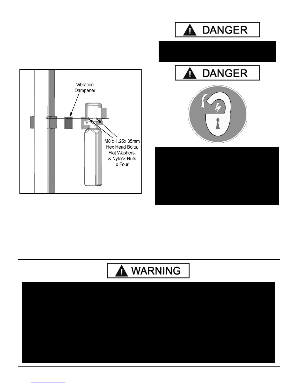
STEP 8
(Mounting the Hydraulic Power Unit)
1. Attach the Power Unit to the POWERSIDE COLUMN.
install the Vibration Dampener between the Power Unit
and the Power Unit Mounting plate on the Powerside
Column, using four M8 Hex Head Bolts and Nuts supplied.
(See Fig 8.1)
Fig 8.1.
DANGER !
ALL WIRING MUST BE PERFORMED
BY A LICENSED ELECTRICIAN.
DANGER!
2. Fill the reservoir with 10 WT. HYDRAULIC OIL OR
DEXRON TYPE III ATF, approximately four gallons. Make
sure the funnel used to fill the Power Unit is clean.
Do not connect Power Unit Hydraulic Hose Assembly at
this time.
WARNING!
DO NOT run Power Unit with no oil. Damage to pump can occur.
The Power Unit must be kept dry. Damage to Power Unit caused by water or other liquids
such as detergents, acid etc., is not covered under warranty.
Operate lift only between temperatures of 41 °- 104° F.
DO NOT PERFORM ANY MAINTENANCE OR
INSTALLATION OF ANY COMPONENTS WITH OUT
FIRST ENSURING THAT ELECTRICAL POWER HAS
BEEN DISCONNECTED AT THE SOURCE OR PANEL
AND CANNOT BE RE-ENERGIZED UNTIL ALL
MAINTENANCE AND/OR INSTALLATION
PROCEDURES ARE COMPLETED.
3. The standard Power Unit for your lift is 220 volt, 60HZ,
single phase. All wiring must be performed by a certified
electrician only. SEE WIRING INSTRUCTIONS AFFIXED
TO MOTOR FOR PROPER WIRING INSTRUCTIONS.
Improper electrical hook-up can damage motor and will not be covered under warranty.
Motor can not run on 50HZ without a physical change in motor.
Use a separate breaker for each Power Unit.
Protect each circuit with time delay fuse or circuit breaker.
For 208-230 volt, single phase, use a 25 amp fuse.
For 208-230 volt, three phase, use a 20 amp fuse.
For 380-440 volt, three phase, use a 15 amp fuse.
1515
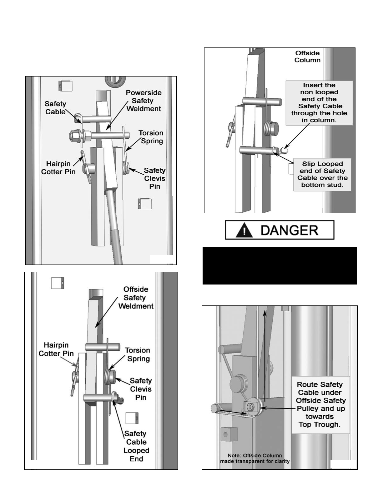
STEP 9
(Installing the Safeties and Safety Cable)
2. From the Offside Column insert the non looped end
of the Safety Cable through the hole located to the right of
the Offside Safety Weldment. (See Fig 9.3)
1. Install Safety Weldments into each respective Column.
(See Figs 9.1 & 9. 2)
Fig 9.3
Fig 9.1
DANGER !
ENSURE THAT BOTH THE
POWERSIDE & OFFSIDE SAFETIES ENGAGE
PROPERLY PRIOR TO LIFT OPERATION.
3. Route the Cable under the Pulley and take it up to the
Top Trough. (See Fig 9.4)
Fig 9.2
Fig 9.4.
1616
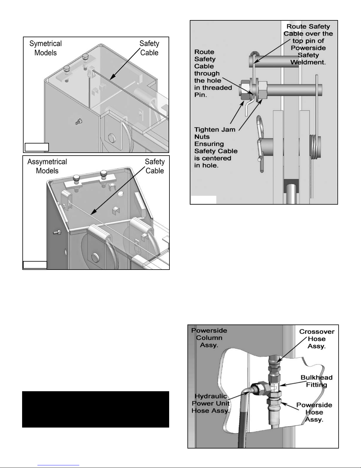
4. Route the Cable through the Top Trough Safety Cable
Pulley(s) and across the lift. (See Figs 9.5 & 9.6)
Fig 9.5
Fig 9.6
5. Route the Cable the same way on the Powerside
going back down the Column.
6. Route the Cable over the top pin on the Safety Handle.
Insert the Cable end through the hole on the Threaded
Post. (See Fig 9.7)
7. Pull the slack out the Safety Cable and hold tension
as the Cable is being tightened. Tighten jam nuts on
either side of the Cable to secure it into place.
(See Fig 9.7)
Fig 9.7
STEP 10
(Installing Hydraulic Lines)
1. Install the Bulkhead Tee Fitting into the Powerside
Column. The through hole is located approximately 90
inches from the floor on the back wall of the Powerside
Column.
2. Connect the Powerside Cylinder Hose to the tee fitting
Be sure to route the hose through the retainer rings inside
the columns.
3. Route the Offside Cylinder Hose (Crossover Hose) up
through the Column and across the Top Trough, down the
Column and connect it to the Bulkhead Tee Fitting.
(See Fig 10.1)
NOTE:
Make sure to tighten both nuts equally so as to
keep the Safety Cable centered
17
17
Fig 10.1
WARNING!
When routing the Hydraulic Hose through the
Columns, make sure to route through the
retaining rings welded inside each Column.
Make sure that the Hose is clear of any moving
parts. It may be necessary to tie Hose clear by
using nylon tie straps or wire.
Fig 10.2
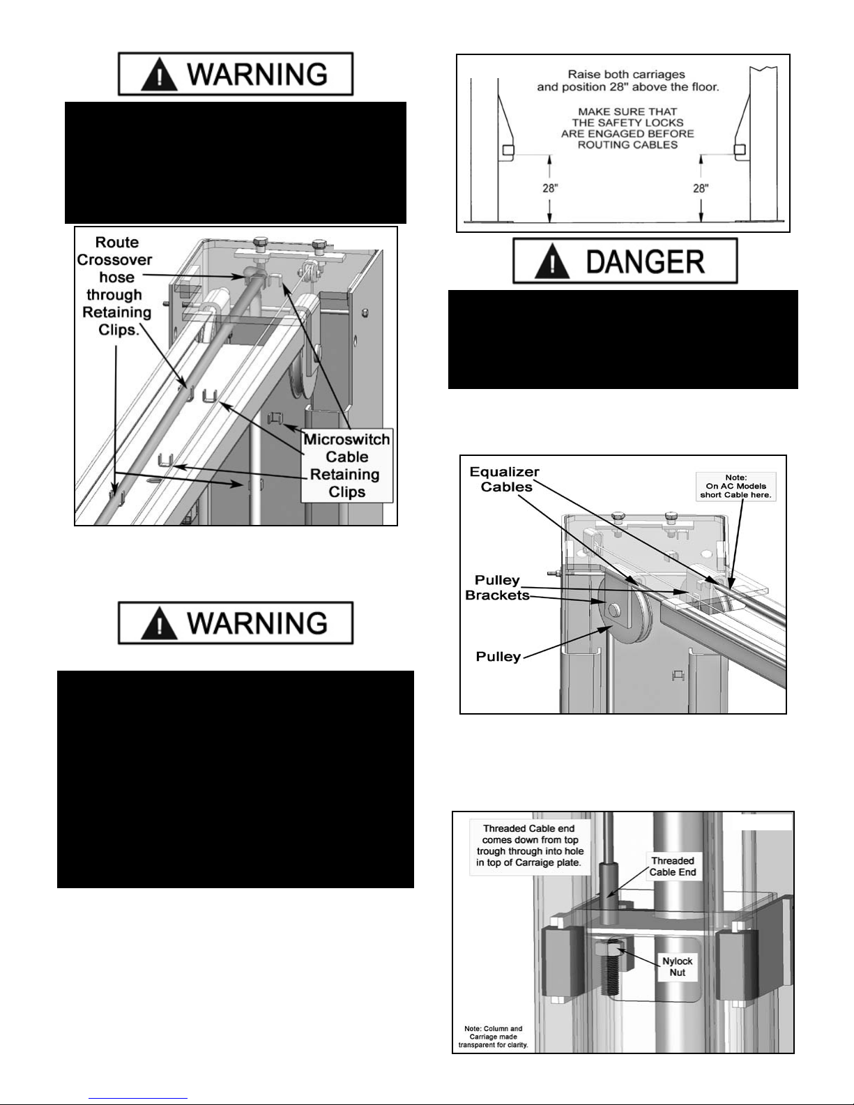
Fig 11.1
DANGER !
Make sure that the safety locks on each Column are
fully engaged before attempting to route
equalizer cables and/or hoses. Carriages must be
equal height from the floor before proceeding.
3. Route the Cables through the Pulley Brackets and
reinstall the Pulleys. (See Fig. 11.2)
Note: The Pulleys should have been removed in Step 6.
STEP 11
(Routing the Equalizers Cables)
WARNING!
WHEN THE CABLE ADJUSTING NUTS BOTTOM OUT
ON THE THREADED END OF THE CABLE
CONNECTOR AND THERE IS STILL SLACK IN THE
CABLES, THE CABLES HAVE STRETCHED BEYOND
THE SAFE USEFUL LENGTH AND NEED TO BE
REPLACED WITH FACTORY APPROVED CABLE
ASSEMBLIES. DO NOT PLACE WASHERS, SPACERS
OR OTHER DEVICES TO “SHORTEN” THE
EFFECTIVE CABLE LENGTH AS DAMAGE TO THE
LIFT OR INJURY TO PERSONS MAY OCCUR.
Refer to illustrations on Page 10.
1. Raise and lock each Carriage approximately 28”
above the ground. (See Fig. 11.1)
Fig. 11.2
4. Insert the Threaded end of the Cable through the
hole on top of the Carriage. Place M-18 washer and
M-18 Nyloc Nut on threaded Cable end. Tighten Cable
Nuts until taut, checking that both Cables have equal
tension. (See Fig 11.3)
Fig. 11.3
2. With the Carriages locked at 28” off the floor, route
the Equalizer Cables up to the Top Trough.
1818
 Loading...